Article

Simulation and Experimental Study on the Shrub-Cutting Performance of Quasi-Planetary Cutter

Key Laboratory of Sustainable Forest Management and Environmental Microorganism Engineering of Heilongjiang Province, Northeast Forestry University, Harbin 150040, China
*
Author to whom correspondence should be addressed.
Appl. Sci. 2025, 15(12), 6937; https://doi.org/10.3390/app15126937
Submission received: 16 April 2025 / Revised: 5 June 2025 / Accepted: 17 June 2025 / Published: 19 June 2025

Abstract

:
To evaluate the performance of quasi-planetary cutting tools, three shrubs were selected and studied using a combination of numerical simulation and cutting test bench experiments. Based on the constitutive model of shrub material and LS-DYNA simulation, the effects of tool speed (n), feed speed (v), and shrub diameter (Da) on peak cutting force (Fmax) and peak cutting power (Pmax) were analysed through a single-factor simulation test. Using the shrub-cutting test bench, an orthogonal test was designed with n, v, and moisture content (w) as factors and Fmax and Pmax as indicators. A regression model was established, and a single-factor comparison test for w was conducted. The results indicate that Fmax decreases as n increases, while Pmax initially decreases and then increases. Both Fmax and Pmax increase with rising v and Da. As w increases, Fmax and Pmax first decrease and then increase. When n is 1813 r/min, v is 30 mm/s, and w is 10.9%, Fmax and Pmax reach their optimal values of 8.42 N and 282.99 W, respectively, with verification test errors of 2.68% and 1.56%. The findings provide methodological and data support for studying the cutting performance of new cutting tools.

1. Introduction

The scope of forest tending operations includes the cutting of forest shrubs. Clearing forest shrubs improves the growth environment of forest trees and facilitates their development and reproduction. A shrub is a woody plant without a distinct trunk, and its physical properties are similar to those of ordinary woody plants [1]. Shrubs exhibit notable structural differences in axial and radial directions, leading to significant variations in their physical and mechanical properties depending on orientation—a characteristic known as anisotropy [2]. This property is commonly applied in finite-element simulations to model the deformation behaviour of shrub materials under external forces using a linear elastic orthotropic material constitutive model [3].
When employing the constitutive model of linear elastic orthotropic materials, most scholars list the relevant parameters but do not specify how these parameters are obtained [4,5]. The orthotropic anisotropy parameters of different shrubs vary considerably, necessitating experimental measurement and calculation of mechanical and physical properties such as density, elastic modulus, and Poisson’s ratio. Mechanical property testing of wood primarily involves a universal mechanical testing machine and material mechanics methods, in which wood samples undergo compression and shear tests to determine mechanical and physical parameters [6]. Based on a specific form of orthogonal anisotropy—transverse anisotropy—this study conducted axial and radial compression tests on shrubs. Through analysis and calculation, the mechanical parameters of the homotropic and heterotropic surfaces of shrubs were obtained. By incorporating shrub density, the material constitutive properties of shrubs were determined.
Shrubs are hard-stemmed plants with a high degree of lignification, significant hardness, and other characteristics that make them difficult to cut. This challenge is particularly evident in their high power consumption and low cutting efficiency [7]. The most common cutting methods for hard-stemmed plants are reciprocating cutting and rotary cutting.
Reciprocating cutting operates through the linear movement of the blade, creating a shearing effect to achieve the cutting action. This method offers high cutting precision, flexible operation, and other advantages. To reduce the cutting force and ensure the quality of the cut section in the stubble trimming of Caragana korshinskii (C.K.), Haifeng Luo et al. [8] proposed a concentric curved-edge sliding cutter. They developed a shear test bench to analyse its cutting characteristics, established a regression model, and determined the optimal shearing parameter combination. However, reciprocating cutting has a limited range, is unsuitable for rapid operation over large areas, and is prone to blade damage from impacts. Rotary cutting, by contrast, achieves cutting through the high-speed rotation of the blade, using centrifugal force and blade sharpness to slice or strike the vegetation. This method is characterised by high cutting speed, efficiency, and strong adaptability. Yaoyao Gao et al. [9] constructed a circular saw blade cutting test bench for C.K., designing both single-factor and orthogonal tests to assess the effects of sawing speed, feed speed, number of teeth, and cutting angle. They determined the optimal sawing parameters for C.K.: a sawing speed of 45.24 m/s, a feed speed of 0.34 m/s, a cutting angle of 10°, and 100 teeth. These optimised parameters reduced the cutting power consumption of C.K. sawing and improved the cutting quality. Given its high efficiency and strong adaptability, rotary cutting has become the predominant method for shrub cutting.
Based on the cutting characteristics of shrubs and the configuration of planetary gears [10], this study designed a quasi-planetary shrub-cutting tool. The three blades are arranged in an equilateral triangle, and the entire tool rotates via the spindle to cut shrubs.
To study cutting performance, finite-element analysis of cutting can be conducted using software such as ABAQUS, ANSYS/LS-DYNA, and ADAMS in conjunction with actual cutting tests. This combination ensures the authenticity and reliability of test data by providing complementary insights. Minmin Qiu et al. [11] employed numerical finite-element simulation and experimental design to investigate the influence of internal and external factors of sugarcane on cutting quality. They utilised an orthogonal test method to determine the optimal combination of cutting system parameters and subsequently verified the cutting quality through experimental tests.
Following the principles of orthogonal testing, Yanmei Meng et al. [12] used ANSYS/LS-DYNA finite-element simulation software to analyse stress variations during the cutting of mulberry branches with circular saws. They identified the optimal working parameters for circular saws, constructed a mulberry branch-cutting test bench, and compared the resulting surface quality of the cut branches. Similarly, Zhi Li et al. [13] used ADAMS software to establish a virtual prototype of a sugarcane-cutting system. They examined the effects of different harvester forward speeds and cutting disc speeds on sugarcane stalk cutting time, deriving an empirical regression equation linking the cutting tool speed, harvester forward speed, and cutting time. Through optimisation, they determined the ideal speed range and forward speed range.
However, shrubs differ from other agricultural and forestry crops in several ways. There are many shrub species, their growing environments are complex, forest roads are often muddy, and the tool’s working parameters may vary accordingly. In order to evaluate the cutting performance of quasi-planetary cutting tools and to optimise their operating parameters in bush-cutting applications, three representative shrub species from Zhangguangcai Ridge were selected as test materials. To improve the efficiency of tool-cutting performance testing, LS-DYNA simulation and a cutting test bench were employed. A single-factor simulated cutting test was conducted, considering tool speed, feed speed, and shrub diameter as variables. Additionally, an orthogonal cutting test was designed using tool speed, feed speed, and shrub moisture content as factors.
By comparing the results of the single-factor cutting test and the orthogonal test, the effects of these parameters on peak cutting force and peak cutting power were analysed. A regression model was then established to optimise the minimum peak cutting force and minimum peak cutting power. This optimisation process yielded a reasonable matching relationship between tool speed and feed speed as well as the best timing and season (based on optimal moisture content) for shrub cutting.

2. Materials and Equipment
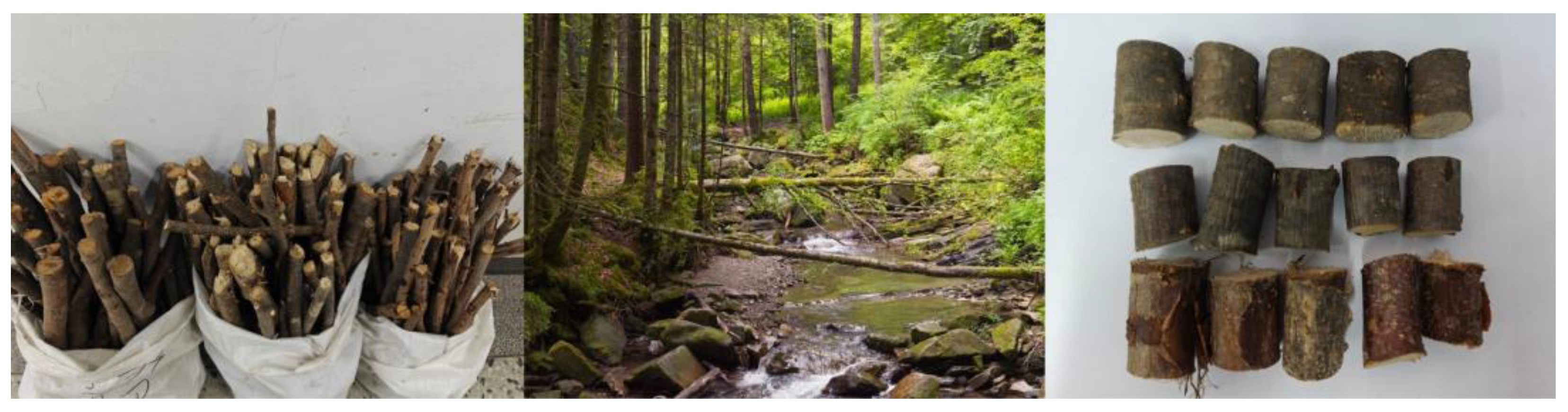
2.1. Materials

2.1.1. Preparation

As shown in Figure 1, the shrubs used in this experiment were collected from Zhangguangcai Ridge, located in the Changbai Mountain range in Heilongjiang Province. This ridge lies along the central axis of the northern section of the eastern mountainous region in Northeast China and is home to a wide variety of shrubs. Three representative species with different mechanical properties—Alnus hirsuta (A.H.), Syringa amurensis (S.A.), and Corylus heterophylla (C.H.)—were selected for this study [14].
The sampling method was based on the Test Methods for Physical and Mechanical Properties of Small Clear Wood Specimens (GB/T 1927-2021) [15]. The collected shrubs exhibited straight growth and were free from pests and scars. Only the main stems were retained, while excess branches were removed. A portion of the shrubs, with diameters of approximately 20 mm, was sawn into 20 mm long segments for subsequent physical property testing. The remaining shrubs were categorised by diameter and used in the quasi-planetary cutter test rig. All shrub materials were wrapped in plastic film and stored in a refrigerator for future use.

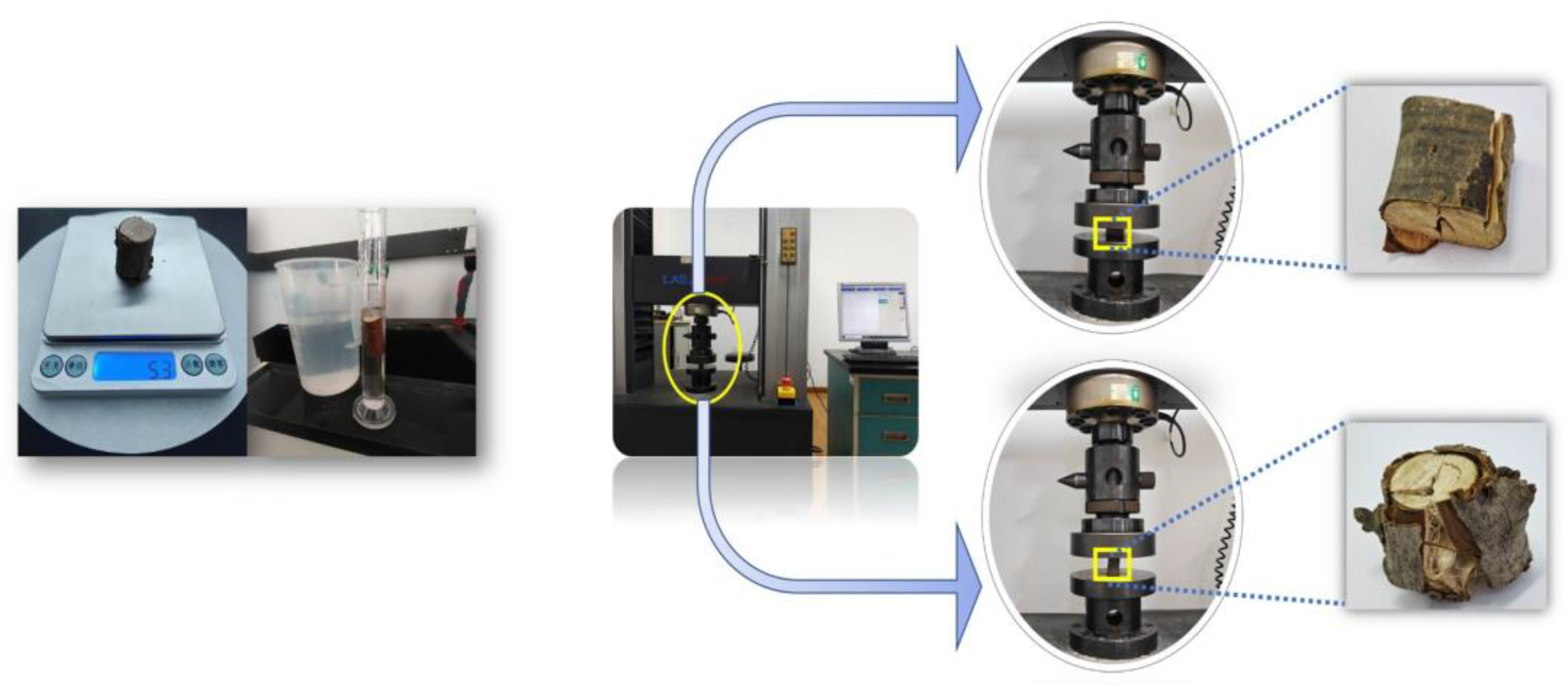
2.1.2. Physical and Mechanical Properties

The constitutive model describes the relationship between a material’s physical and mechanical properties and external loads using mathematical expressions. It reflects the deformation behaviour and mechanical response of materials under different loading conditions, particularly the derivation of mechanical properties from the relationship between stress and strain. The constitutive model can represent a material’s elasticity, plasticity, viscosity, and other properties, allowing for the prediction of its response under various loading conditions.
Orthotropic constitutive models are commonly used to describe the physical and mechanical properties of materials. Transverse isotropy is a specific type of orthotropic behaviour [16]. This means that in a particular direction, usually referred to as the longitudinal or axial direction, the mechanical properties differ from those in the perpendicular direction. However, within the plane perpendicular to this direction, the properties remain uniform.
Based on the assumptions of the shrub model, shrub material can be regarded as a transversely isotropic material. In the section perpendicular to the longitudinal direction, the mechanical properties in the radial and tangential directions are approximately the same. This interface is known as a homogeneous plane, whereas a plane with differing mechanical properties is called a heterogeneous plane. The transversely isotropic constitutive model includes various mechanical parameters on the homogeneous and heterogeneous planes, such as density (ρ), elastic modulus (EL, ER, and ET), Poisson’s ratio (μLR, μLT, and μRT), and shear modulus (GLR, GLT, and GRT).
Appropriate methods must be employed for the calculation and measurement of the parameters in the constitutive model, as shown in the density test and compression test of shrubs given in Figure 2. An electronic balance and a graduated cylinder were used to determine the density of each shrub material using the displacement method. An LD23-104 microcomputer-controlled electronic universal testing machine was utilised to conduct axial and radial compression tests on the shrubs. The experiment was conducted in accordance with GB/T 1935-2009 Method of Testing in Compression Parallel to Grain for Wood [17]. Bush samples were sequentially placed at the centre of a spherical sliding support. To apply pressure to the samples, a flat compression plate was loaded downward at a constant rate of 5 mm/min until structural deformation and failure occurred, marking the end of the test. From these tests, the slope of the stress–strain curve was obtained, representing the shrub’s elastic modulus. The anisotropic (EL, GRT, and μRT) and isotropic (ER, ET, μLR, μLT, GLR, and GLT) plane parameters of the bush constitutive model were derived from axial and radial compression testing, respectively. For isotropic materials, as indicated by Equation (1), the relationship between shear strain and shear stress, along with the expression of shear strain in the generalized Hooke’s law, leads to the derivation of the relationship between shear modulus, Young’s modulus, and Poisson’s ratio, as shown in Equation (2).
γ = τ G γ = 2 1 + μ E τ
G RT = E R 2 1 + μ RT G LR = E L 2 1 + μ LR
In these equations, τ represents the shear strain (MPa). γ represents the shear strain. GLR represents the shear modulus of the shrub’s homogeneous plane (MPa), where GLR = GLT. GRT denotes the shear modulus of the shrub’s heterogeneous plane (MPa). ER is the elastic modulus of the shrub’s homogeneous plane (MPa), where ER = ET, while EL is the elastic modulus of the shrub’s heterogeneous plane (MPa). μLR is the Poisson’s ratio of the shrub’s homogeneous plane, where μLR = μLT, and μRT is the Poisson’s ratio of the shrub’s heterogeneous plane.
Referring to the Poisson’s ratio values of other types of wood and based on related research [18,19], the Poisson’s ratios for the homogeneous planes of A.H., S.R., and C.H. were taken as 0.41, 0.40, and 0.36, respectively. As demonstrated by relevant experimental studies, the Poisson’s ratio in the heterogeneous wood plane is typically approximately one-tenth of that in the homogeneous plane. Accordingly, for the heterogeneous planes, the Poisson’s ratios were taken as 0.041, 0.040, and 0.036, respectively.
Based on these results, the constitutive model parameters for the three types of shrubs were obtained and are listed in Table 1. According to their physical properties, the three shrubs were assigned the following numerical designations.

2.2. Equipment

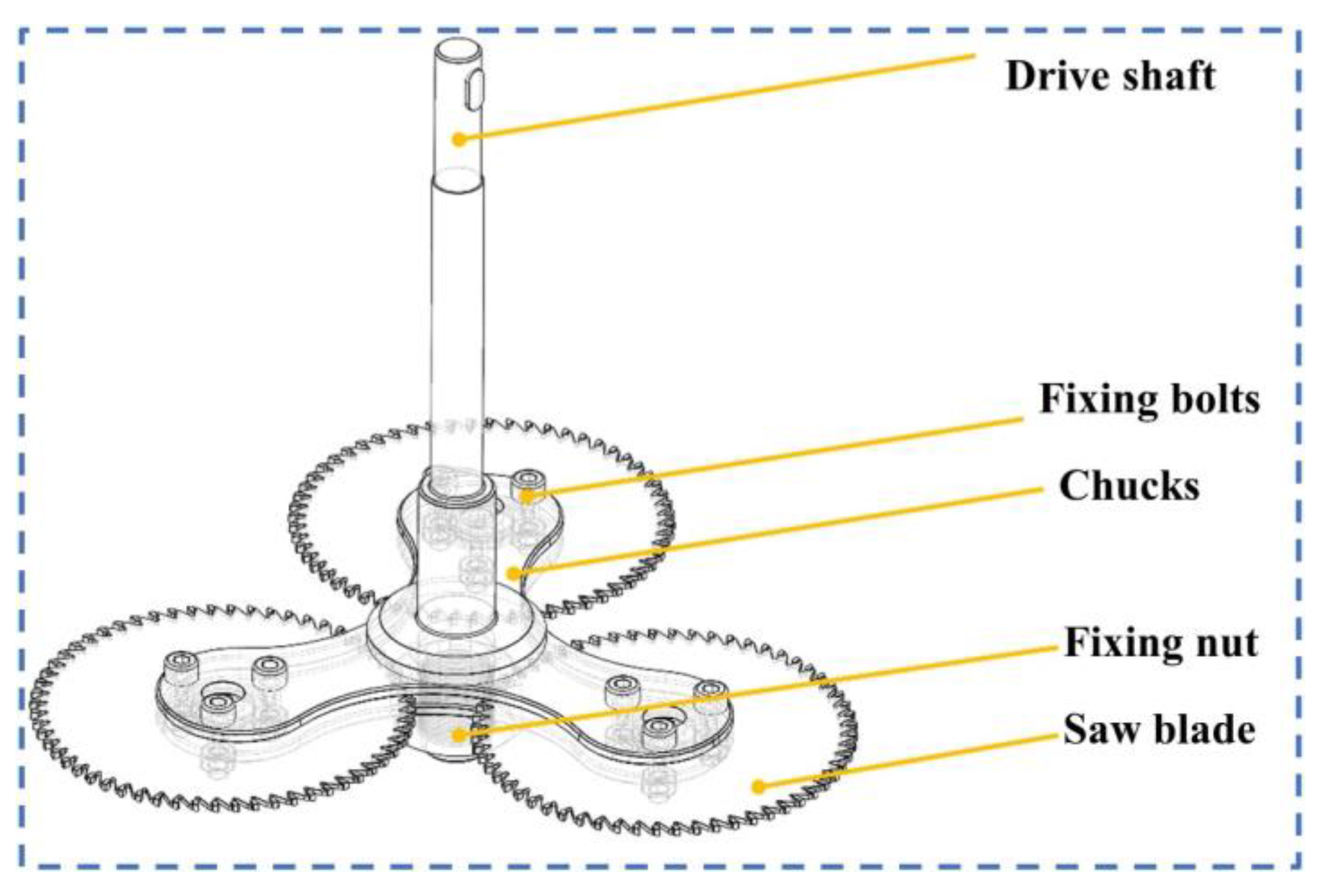
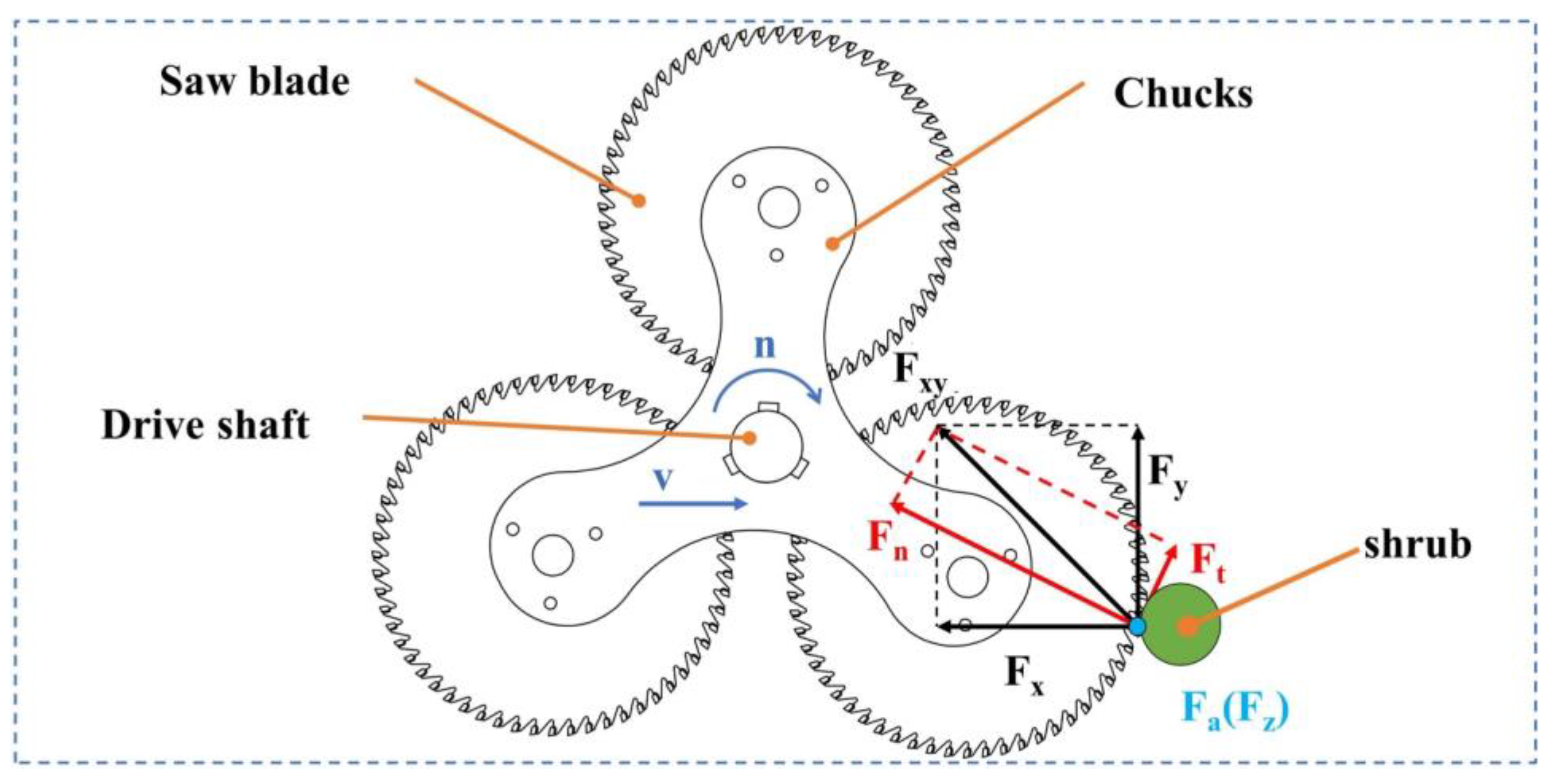
2.2.1. Quasi-Planetary Shrub Cutter

A quasi-planetary cutter holder was designed based on the cutting characteristics of shrubs, drawing inspiration from the distribution pattern of planetary gears in a planetary gear reducer. The saw blades were evenly distributed at an angle of 120° on the cutter flange and were securely fixed together to form a unified quasi-planetary cutter structure, as shown in Figure 3. Table 2 presents the tool parameters.
As shown in Figure 4, during shrub cutting, the quasi-planetary tool rotates around its axis at a speed of n while advancing towards the shrub at a feed speed of v, maintaining the cutting plane perpendicular to the shrub branch. During the cutting process, the cutter rotates at high speed and comes into contact with the shrub branch. Due to the complexity of the actual cutting process, the cutting forces acting on the cutter can generally be classified into tangential force Ft (N), radial force Fn (N), and axial force Fa (N). The tangential force Ft (N) is primarily generated by the reaction force of friction as the cutter slices through the shrub, with its direction parallel and opposite to the linear velocity of the quasi-planetary cutter. The radial force Fn (N) results from the impact force exerted by the shrub on the cutter during cutting as well as the reaction force from the elastic deformation of the shrub, with its direction pointing towards the main spindle. The axial force Fa (N) is mainly caused by installation and processing errors of the cutter, along with the extrusion and collision of shrub branches against the cutter, with its direction aligned along the rotational axis and perpendicular to the cutter surface.
The relationship between the cutting force F (N) and its components is given in Equation (3).
F = F n 2 + F t 2 + F a 2 = F x 2 + F y 2 + F z 2

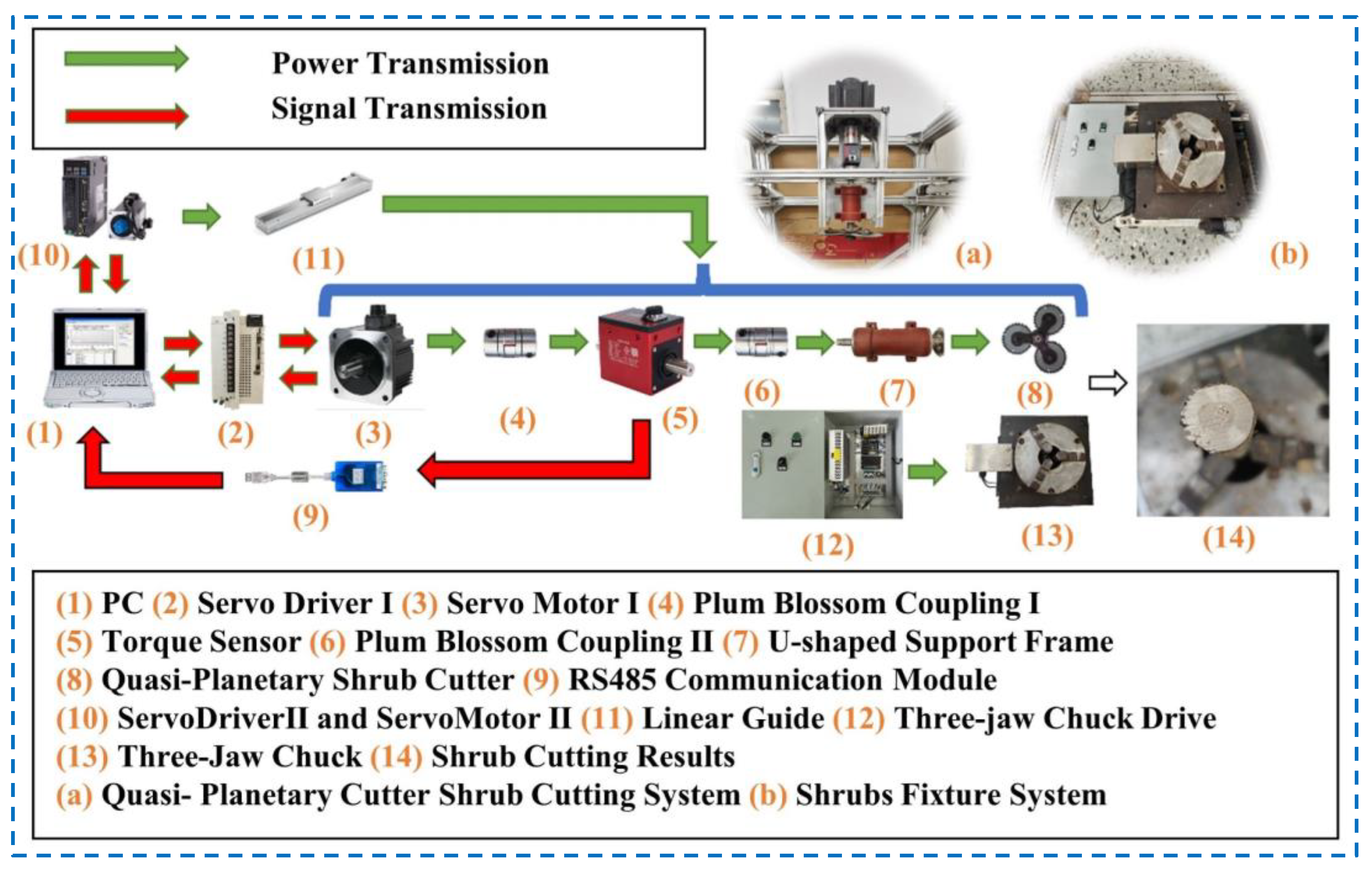
2.2.2. Cutting Test Device

As shown in Figure 5, a quasi-planetary shrub cutter test device was designed. In addition to the quasi-planetary cutter, it primarily comprises a frame, drive system, feeding system, clamping device, and measuring system [20,21]. The frame was constructed using 80 × 80 mm and 40 × 40 mm aluminium profiles from MISUMI, providing high load-bearing capacity and structural stability, which helped minimise vibrations during the shrub-cutting test.
The drive system utilised a Panasonic servo motor (model MDMF402L1H6M, rated power: 4 kW, rated speed: 2000 r/min, maximum speed: 3000 r/min, was manufactured by Panasonic Corporation, headquartered in Osaka, Japan) as the power source. Power was transmitted to the quasi-planetary shrub cutter via two-star couplings and a U-shaped bracket. A Panasonic servo driver (model MFDLTB3SF, was manufactured by Panasonic Corporation, headquartered in Osaka, Japan.), controlled by a PC, enabled full control of the motor’s speed, position, and torque through a fully closed-loop control mode. The speed control mode was primarily used in this experiment to adjust the servo motor speed, thereby regulating the cutter’s cutting speed.
The feeding system consisted of two fully enclosed linear modules, powered by a servo motor (model Delta ECMA-C20807RS, rated power: 0.75 kW, rated speed: 3000 r/min, was manufactured by Delta Electronics, Inc., headquartered in Taoyuan City, Taiwan) and controlled by a Delta servo controller. The feeding speed was precisely regulated via commands from the host PC and was limited by travel switches. The fully enclosed linear modules offered strong dust-proof capabilities, effectively preventing wood chips from entering the modules and causing wear during the shrub-cutting test, thereby ensuring the accuracy of the experiment.
The clamping device utilised an electric three-jaw chuck to simulate the fixation of shrub roots, ensuring high reliability. It was also equipped with a jaw pressure valve, allowing for automatic clamping without damaging the shrub branches.
The measuring system employed a DAYSENSOR dynamic torque sensor (model DYN-200, was manufactured by DaySensor, headquartered in Shenzhen City, China) with a torque measurement range of 0–100N·M, a speed measurement range of 0–10,000 r/min, and an error of less than ±0.1%. It was paired with a 200 torque measurement system software, which accurately outputted torque, speed, and power data to the PC.
In the shrub-cutting experiment, the torque signal from the dynamic torque sensor was recorded in real time using a data acquisition system. Prior to contact between the cutter and bush, the torque remains essentially stable at the no-load value, with minimal fluctuations. At the moment of contact, the torque increases sharply and constantly rises during the cutting process, reaching a peak value. Once the bush is fully cut, the torque returns to the no-load level, with minimal fluctuations again. The peak torque (M) was recorded during the test. As shown in Equations (4) and (5), by processing the torque signal, the cutting force (F) and cutting power (P) of the shrub were obtained as follows:
F = M r
P = 2 π n M ( t ) d t t
where M is the torque (Mpa); r is the rotation radius of the quasi-planetary shrub cutter (m); n is the rotational speed of the quasi-planetary shrub cutter (r/min); M(t) is the torque sensor curve as a function of time; and t is the time variable (s).

3. Methods and Experimental Design

3.1. Finite-Element Single-Factor Simulation Experiment

3.1.1. Indicators and Factors

Cutting force [22] and cutting power [23] are crucial parameters in evaluating the cutting performance of a tool, reflecting energy consumption during the cutting process, the force exerted on the tool, and the efficiency of shrub material removal. These two parameters were selected as the evaluation criteria for the single-factor experiment.
The primary movements of the tool include rotational motion and feed motion, with tool rotational speed and feed rate being the most critical influencing factors in the cutting process. The intrinsic properties of the shrub also significantly influence cutting performance, particularly variations in diameter [24] and moisture content [25,26], which greatly affect the ease or difficulty of cutting. The distribution of moisture within the shrub is complex, making it difficult to establish a finite-element model related to its moisture content. Therefore, only the diameter of the shrub is considered in the simulation of the single-factor experiment, while moisture content will be investigated in subsequent cutting tests on the test bench.
The key cutting parameters considered as influencing factors are the quasi-planetary tool rotational speed (n), the feed speed (v), and the diameter Da at the actual cutting position of the shrub. These factors substantially impact the cutting force and cutting power of the tool.
Before the experiment, a pre-cutting test was conducted on the tool. The test indicated that when the tool’s rotational speed (n) is below 1000 r/min, shrub-cutting efficiency is low, leading to incomplete cuts, excessive noise, and tool vibration. These negative effects are further exacerbated by an excessively high feed speed at low rotational speeds. Given the poor road conditions in forested areas, which result in slower forward speeds for brush cutters, and considering the maximum speed limitations of the test bench equipment’s motor, the quasi-planetary tool rotational speed (n) was set between 1000 and 2000 r/min, with a feed speed (v) of 30 to 90 mm/s. The shrub diameter, Da, was set between 10 and 40 mm, with a length of 2000 mm. The levels of the experimental factors are listed in Table 3.

3.1.2. Finite-Element Modelling

In the finite-element simulation of cutting, the quasi-planetary shrub cutter and shrub models were simplified to improve computational efficiency, reduce simulation complexity, and minimise the probability of errors. The bolts, nuts, and washers of the cutter were omitted, leaving only the teeth, cutter flange, and part of the spindle. The shrub was simplified into a cylindrical shape, with its axis perpendicular to the ground and fully constrained at the bottom. Simplified 3D models of the quasi-planetary shrub cutter and shrub were created using SolidWorks 2022 software. The 3D models were then imported into LS-PrePost 2024, the pre-processing and post-processing software of LS-DYNA, in STEP format to establish the finite-element cutting model.
The cutter material was defined as a bilinear kinematic hardening plastic model (MAT_PLASTIC_KINEMATIC). This model is primarily used to describe the elastic–plastic behaviour of materials and is particularly suitable for metals. It was applied to a 65 Mn cutter to improve computational efficiency and facilitate the extraction of the cutter’s stress and strain. The material parameters of 65 Mn are listed in Table 4. The flange used to mount and secure the cutter head was modelled as a rigid material, with 45# steel (equivalent to AISI 1045) as the selected material. Its properties are as follows: a density of 7850 kg/m3, a Young’s modulus of 206 Gpa, and a Poisson’s ratio of 0.269.
The three shrubs selected were modelled using a linear elastic orthogonal anisotropic material model [27], which best matched the mechanical properties of wood. Additionally, the keyword MAT_ADD_EROSION was included to simulate material failure during cutting. The material compositions are listed in Table 1.
A mesh is crucial in finite-element simulations since it decomposes complex geometries into simpler elements, making numerical calculations feasible. A well-designed mesh enhances computational accuracy and efficiency while also influencing the stability and convergence of the solution. Although finer meshes capture more physical phenomena, they also increase computational costs. Therefore, achieving a balance in mesh design is essential.
Due to the complex structure of the cutter, tetrahedral meshing was employed to improve mesh quality and enhance computational efficiency and accuracy. The mesh density was increased around the serrated parts of the cutter. For the simplified shrub, hexahedral meshing was applied, with a higher mesh density in the cutting section that comes into contact with the cutter teeth. The total meshes of the model were 137,085. The total nodes of the model were 74,123. The mesh number was doubled, revealing that when the total mesh number was 274,170, the maximum stress value in the blade slightly decreased (i.e., by 2%). Therefore, the coarser meshing scheme of 137,085 elements was applied to all the models in the simulation tests. The finite-element model after meshing is shown in Figure 6.
To simulate shrub-root fixation, a full constraint was applied to the bottom surface of the simplified shrub model. Simultaneously, the rotational speed along the Z-direction and feeding speed along the XY-plane were applied to the entire cutter. The cutting height was set to 10 cm, using the bottom surface of the shrub as the reference plane.
Considering the actual cutting process, in which the serrated surface of the cutter interacts with the cutting surface of the shrub, the shrub eventually undergoes failure and fracture. Therefore, surface-to-surface contact erosion (ERODING_NODES_TO_SURFACE) was selected. The static friction coefficient was set to 0.1, the dynamic friction coefficient to 0.2, and all other parameters were kept at their default settings.
The CONTROL and DATABASE settings are key components that directly influence finite-element simulation reliability. CONTROL allows for adjusting parameters such as time step and energy to ensure accuracy and stability. In this study, the keywords “ENERGY”, “HOURGLASS”, “TERMINATION”, and “TIMESTEP” were included in the simulation model. “ENERGY” ensures energy conservation, “HOURGLASS” prevents numerical instability, “TERMINATION” sets the end time based on the bush diameter (0.4–0.6 s), and “TIMESTEP” controls the time step (initial value: 0, scale factor: 0.9, and computed step: −1 × 10⁻⁷).
DATABASE settings manage the output format and simulation result contents, such as stress and strain distributions. The keywords “ASCII_option”, “BINARY_D3PLOT”, and “EXTENT_BINARY” were used to export the results in multiple formats for further analysis.
After importing the final finite-element model into LS-Run, the results were visualised using LS-PrePost 2024 software. As shown in Figure 7, it illustrates the cutting process for A.H. at a rotational speed of 1750 r/min, a feed speed of 60 mm/s, and a shrub diameter of 20 mm. Four key moments during the process are shown, from the initial contact with the shrub to the complete cutting.
Throughout the cutting process, the maximum stress on the tool was 240.416 Mpa, which is well below the yield limit of the tool material (440 Mpa).

3.2. Orthography Experimental Design

Based on the results of the single-factor simulation experiment and following the principles of the Box–Behnken experimental design, a three-factor, three-level experiment was designed, with the peak cutting force and peak cutting power as evaluation indicators. The selected test material was A.H. with a diameter of 20 mm, and the factors considered were the quasi-planetary tool rotational speed (n), feed speed (v), and shrub moisture content (w). Each test group was repeated five times to ensure the reliability and accuracy of the results. The levels of the orthogonal experimental factors are shown Table 5.

4. Results and Discussion

4.1. Single Experiment Simulation Results and Analysis

The single-factor simulation results for the three types of shrubs are illustrated in Figure 8, Figure 9 and Figure 10. Although the quasi-planetary tool cuts three different types of shrubs, the influence of the three experimental parameters on the performance indicators of each shrub follows similar patterns, which are largely consistent with the trends observed in the simulated cutting tests.
Increase in Tool Rotational Speed: As shown in Figure 8, the peak cutting force shows a decreasing trend, while the peak cutting power initially decreases and then gradually increases. This occurs because, before the tool induces plastic deformation in the shrub, the shrub undergoes elastic deformation to resist the cutting process. As the rotational speed increases, the duration of elastic deformation decreases, leading to a reduction in peak cutting force and power. However, the tool also requires a certain amount of power to maintain idle rotation, and this idle power increases with rotational speed. When the reduction in peak cutting power is insufficient to compensate for the increase in idle power, an overall increase in power is observed.
Increase in Feed Speed: As shown in Figure 9, both the peak cutting force and peak cutting power follow an increasing trend. Within the examined range of feed speeds, an increase in feed speed leads to a greater volume of material being cut per unit time. A larger cutting volume results in greater resistance from the shrub material, making the cutting process more challenging and thereby increasing both cutting force and power.
Increase in Shrub Diameter: As shown in Figure 10, both the peak cutting force and peak cutting power increase. As the shrub diameter increases, the amount of lignocellulosic material to be removed also rises. Under identical conditions, the increase in the shrub’s cross-sectional area leads to greater cutting resistance and friction between the tool and the shrub stem. Consequently, the peak cutting force and power increase significantly.

4.2. Orthogonal Experiment Results and Analysis

4.2.1. Orthogonal Experiment Results

The results of the orthogonal experiments are listed in Table 6.

4.2.2. Analysis

The experimental results were subjected to multivariate fitting using Design-Expert 13 software, followed by variance analysis. The variance analysis of the experimental results is presented in Table 7. From Table 7, it is evident that the p-values of the models for peak cutting force and peak cutting power are both less than 0.01, indicating that the established regression models are highly significant (p < 0.01 is extremely significant, 0.01 < p < 0.05 is significant, and p > 0.05 is not significant [28]). The p-values for the lack-of-fit terms of the two models are 0.19 and 0.2211, respectively—both greater than 0.05—suggesting that the regression equations exhibit minimal errors and strong fitting performance. The coefficients of determination (R2) for peak cutting force and peak cutting power are 99.36% and 98.54%, respectively, indicating high fitting accuracy and the feasibility of further parameter optimisation within the experimental range [29].
In the peak cutting force model, the first-order terms of tool rotational speed (n), feed speed (v), and shrub moisture content (w) as well as the quadratic term of tool rotational speed (n2) have an extremely significant impact on the model. The quadratic term of feed speed (v2) has a significant impact, whereas the interaction terms between tool rotational speed and feed speed (n·v), tool rotational speed and shrub moisture content (n·w), feed speed and shrub moisture content (v·w), and the quadratic term of shrub moisture content (w2) have no significant impact.
In the peak cutting power model, the first-order terms of tool rotational speed (n), feed speed (v), and shrub moisture content (w) as well as the interaction term between tool rotational speed and feed speed (n·v) and the quadratic term of tool rotational speed (n2) have an extremely significant impact on the model. The quadratic term of feed speed (v2) has a significant impact, whereas the interaction terms between tool rotational speed and shrub moisture content (n·w), feed speed and shrub moisture content (v·w), and the quadratic term of shrub moisture content (w2) have no significant impact.
After removing the non-significant terms, the simplified models are given in Equations (6) and (7):
F = 9.74 1.11 n + 0.6925 v + 0.3105 w + 0.3641 n 2 + 0.1481 v 2
P = 312.29 + 10.85 n + 22.5 v + 9.99 w + 6.83 n v + 6.59 n 2 + 4.79 v 2
The 3D response surfaces [30] for peak cutting force and peak cutting power are shown in Figure 11 and Figure 12, respectively. As rotational speed increases, the peak cutting force exhibits a continuously decreasing trend, while peak cutting power shows a continuously increasing trend. As feed speed increases, both peak cutting force and peak cutting power follow a continuously increasing trend. Similarly, as moisture content increases, both peak cutting force and peak cutting power also exhibit a continuously increasing trend.
As shown in Figure 13, a comparison between the single-factor simulation results and the orthogonal experiment results indicates that the observed trends in rotational speed and feed speed are largely consistent with the patterns identified in the single-factor experiments. The results of the orthogonal experiments are slightly higher than those of the simulations. This discrepancy can be attributed to the fact that the simulation neglected the influence of bush moisture content on the cutting process. Moreover, dynamic factors such as vibration, impact, and rebound occurring during actual bush cutting further contribute to the difference. A single-factor experiment was conducted to further validate the influence of moisture content.
A.H. samples with a diameter of 20 mm and moisture contents of approximately 0.0% (completely dry), 13.9%, 24.6%, 38.3%, and 46.3% were selected. Cutting experiments were performed on the test bench under a tool rotation speed of 1750 r/min and a feed rate of 60 mm/s, using peak cutting force and peak cutting power as evaluation metrics. The experimental results are shown in Figure 14.
As moisture content increases, both peak cutting force and peak cutting power initially decrease and then increase, aligning with the trend depicted in the response curve graph. When cutting relatively dry shrub material, the tool and the cutting surface of the shrub exhibit a dry grinding phenomenon, resulting in higher friction and consequently increasing cutting force and cutting power.
In addition to lubricants and greases, water also functions as a lubricant. As moisture content increases, it provides a lubricating effect at the contact point between the tool and the shrub surface, reducing the coefficient of friction and thereby decreasing cutting force and cutting power. However, as moisture content continues to rise, approaching or exceeding the fibre saturation point of the shrub, the increase in cell-bound water causes the material to become adhesive. This enhances the adhesive forces between shrub fibres, and in a moist environment, shrub chips become difficult to discharge, getting stuck in the teeth of the quasi-planetary cutter. Consequently, the cutting force and cutting power increase.
In summary, conducting operations during early spring, when shrub moisture content is low, can effectively reduce peak cutting force and peak cutting power, improve the efficiency of shrub-cutting operations, and minimise wear on the quasi-planetary cutter.

4.3. Optimization and Test Verification

With the optimisation objective of minimising both peak cutting force and peak cutting power [31], the constraints for the optimisation process are given in Equation (8):
min F ( n , v ) min P ( n , v ) 1500 n 2000 30 v 45 10.9 w 38.3
To validate the optimal parameter combination derived from the model, experimental tests were conducted. The results, as shown in Table 8, indicate that the average peak cutting force measured during the actual cutting tests on the bench was 8.65 N, and the average peak cutting power was 287.46 W. Compared to the predicted values from the optimal parameter combination, the error percentages were 2.68% for peak cutting force and 1.56% for peak cutting power. These small error margins confirm the reliability and accuracy of the model in predicting the optimal cutting conditions.

5. Conclusions

This paper proposes a planetary shrub-cutting tool and, based on the properties of shrubs, develops a planetary shrub-cutting test bench. In combination with finite-element simulation technology, the cutting performance of the new tool was explored:
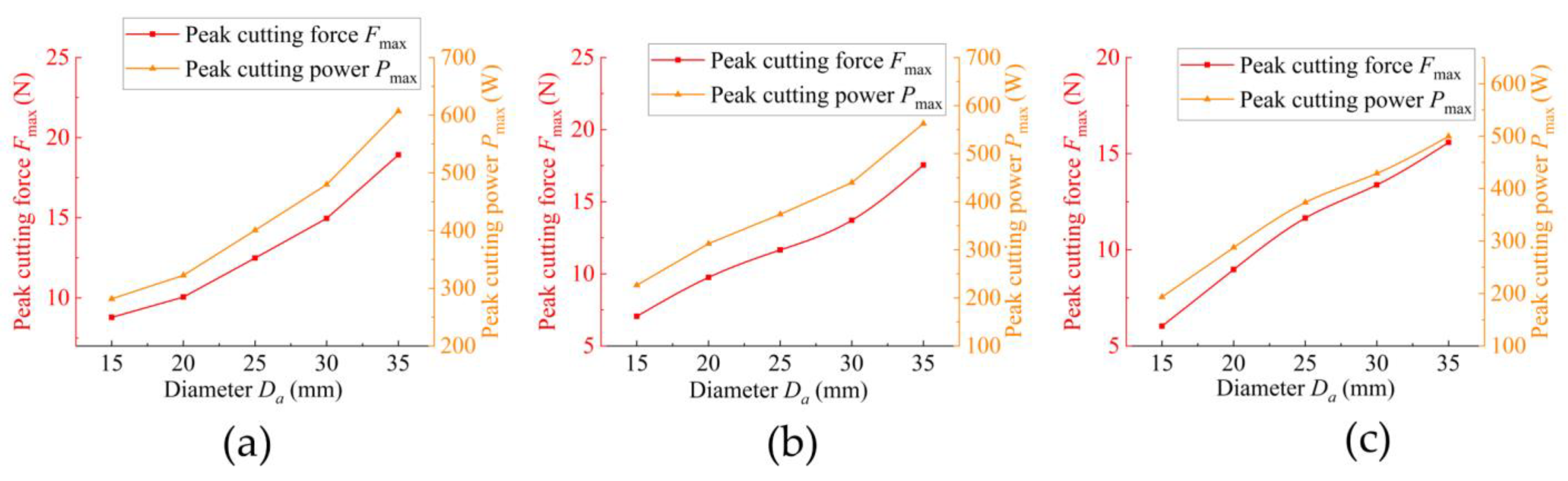
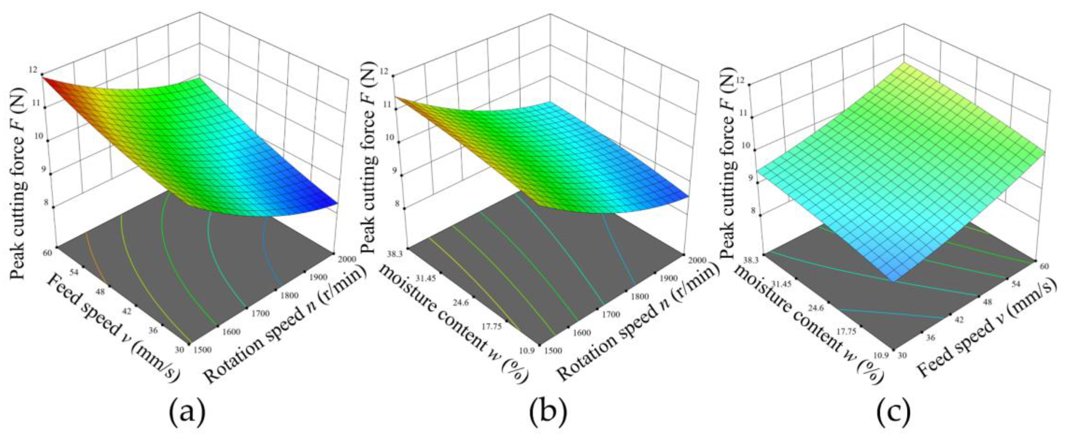
  • Using material mechanics methods and a universal mechanical testing machine, the material constitutive models of three types of shrubs were derived based on their transverse isotropy. Based on these constitutive models, a finite-element model of the planetary tool cutting shrubs was established. Single-factor simulation tests showed that as the tool rotation speed increases, the peak cutting force tends to decrease, while the peak cutting power initially decreases and then gradually increases. As the feed rate increases, both the peak cutting force and peak cutting power increase. Additionally, as the shrub diameter increases, both peak cutting force and peak cutting power also increase;
  • A three-factor, three-level orthogonal experiment was designed based on the constructed test bench. Regression and variance analyses were performed on the results, and a single-factor experiment was conducted with shrub moisture content as the variable. The experimental results showed that as moisture content increases, both peak cutting force and peak cutting power initially decrease and then increase. The results of the multi-factor experiment are consistent with those of the single-factor experiment;
  • With the optimisation objective of minimising both peak cutting force and peak cutting power, optimisation and experimental validation were performed. The results indicated that when the tool rotation speed is 1813 rpm, the feed rate is 30 mm/s, and the shrub moisture content is 10.9%, the peak cutting force reaches 8.42 N, and the peak cutting power reaches 282.99 W, both achieving their optimal values. The errors between the predicted values and the validation test results are 2.68% and 1.56%, respectively [13].

Author Contributions

Conceptualization, Z.S. and X.D.; methodology, Z.S. and X.D.; software, Z.S. and Y.Z.; validation, Z.S. and C.T.; formal analysis, Z.S. and J.Z.; investigation, Z.S.; resources, X.D.; data curation, Z.S.; writing—original draft preparation, Z.S.; writing—review and editing, Z.S.; visualization, Z.S. and B.G.; supervision, X.D.; project administration, Z.S. and C.T. All authors have read and agreed to the published version of the manuscript.

Funding

This research was funded by the National Key Research and Development Program (Grant number: 2022YFD2201001).

Institutional Review Board Statement

Not applicable.

Informed Consent Statement

Not applicable.

Data Availability Statement

The original contributions presented in the study are included in the article, further inquiries can be directed to the corresponding author.

Acknowledgments

Sincere thank also goes to Teng Chi for her kind help in the implementation of the test.

Conflicts of Interest

The authors declare no conflicts of interest.

Abbreviations

The following abbreviations are used in this manuscript:
A.H.Alnus hirsuta
S.A.Syringa amurensis
C.H.Corylus heterophylla

References

  1. Mao, P.; Qin, L.; Hao, M.; Zhao, W.; Luo, J.; Qiu, X.; Xu, L.; Xiong, Y.; Ran, Y.; Yan, C.; et al. An Improved Approach to Estimate Above-Ground Volume and Biomass of Desert Shrub Communities Based on UAV RGB Images. Ecol. Indic. 2021, 125, 107494. [Google Scholar] [CrossRef]
  2. Chen, Y.; Zhang, L.; Mei, C.; Li, Y.; Duan, G.; Agarwal, S.; Greiner, A.; Ma, C.; Jiang, S. Wood-Inspired Anisotropic Cellulose Nanofibril Composite Sponges for Multifunctional Applications. ACS Appl. Mater. Interfaces 2020, 12, 35513–35522. [Google Scholar] [CrossRef] [PubMed]
  3. Sun, F. Comparison Analysis of Moisture-Dependent Orthotropic Elasticity between Earlywood and Latewood in Chinese Fir Using Digital Image Correlation. Ind. Crops Prod. 2024, 220, 119185. [Google Scholar] [CrossRef]
  4. Igathinathane, C.; Womac, A.; Sokhansanj, S. Corn stalk orientation effect on mechanical cutting. Biosyst. Eng. 2010, 107, 97–106. [Google Scholar] [CrossRef]
  5. Xie, L.; Wang, P.; Luo, J.; Yi, W.; Deng, J. Optimisation and Numerical Simulation of Shearing Blade Used for Citrus Seedling Grafting. Biosyst. Eng. 2022, 215, 67–79. [Google Scholar] [CrossRef]
  6. Li, M.; Xu, S.; Yang, Y.; Guo, L.; Tong, J. A 3D simulation model of corn stubble cutting using finite element method. Soil Tillage Res. 2017, 166, 43–51. [Google Scholar] [CrossRef]
  7. Wang, T.; Yan, X.; Mi, G.; Liu, S.; Zhang, Z.; Liu, Z. Research status of hard stem cutting device. J. Chin. Agric. Mech. 2023, 44, 34–39. [Google Scholar] [CrossRef]
  8. Luo, H.; Guo, S.; Zhi, Z.; Kan, J. Sliding Cutting and Cutting Parameters of Concentric Curvilineal Edge Sliding Cutter for Caragana Korshinskii (C.K.) Branches. Forests 2023, 14, 2379. [Google Scholar] [CrossRef]
  9. Gao, Y.; Wang, Y.; Qu, A.; Kan, J.; Kang, F.; Wang, Y. Study of Sawing Parameters for Caragana Korshinskii (C.K.) Branches. Forests 2022, 13, 327. [Google Scholar] [CrossRef]
  10. Sanchez-Espiga, J.; Fuerst, M.; Fernandez-del-Rincon, A.; Otto, M.; Viadero, F.; Stahl, K. On the Behaviour of N-Planets Planetary Gear Sets Influenced by Geometrical Design Factors. Mech. Mach. Theory 2025, 205, 105860. [Google Scholar] [CrossRef]
  11. Qiu, M.; Meng, Y.; Li, Y.; Shen, X. Sugarcane stem cut quality investigated by finite element simulation and experiment. Biosyst. Eng. 2021, 206, 135–149. [Google Scholar] [CrossRef]
  12. Meng, Y.; Wei, J.; Wei, J.; Chen, H.; Cui, Y. An ANSYS/LS-DYNA Simulation and Experimental Study of Circular Saw Blade Cutting System of Mulberry Cutting Machine. Comput. Electron. Agric. 2019, 157, 38–48. [Google Scholar] [CrossRef]
  13. Li, Z.; Lin, Z.; Li, S.; Zhang, H. Optimization Research on the Working Parameters of Sugarcane Harvester on the Cutting Time of Stalks Using Virtual Prototype Technology. Sugar Tech. 2023, 25, 41–56. [Google Scholar] [CrossRef]
  14. Luo, Y.; He, H.; Zhang, Z.; Liu, T.; Yu, Z.; Liu, Z.; Bao, G. Species composition and diversity under different stand densities in Zhangguangcailing. J. Cent. South Univ. For. Technol. 2023, 43, 131–141. [Google Scholar] [CrossRef]
  15. SAC/TC 41. GB/T 1927-2021; Test Methods for Physical and Mechanical Properties of Small Clear Wood Specimens. State Administration for Market Regulation. Standardization Administration of China: Beijing, China, 2021.
  16. Li, P.; Guo, Y.B.; Shim, V.P.W. A Constitutive Model for Transversely Isotropic Material with Anisotropic Hardening. Int. J. Solids Struct. 2018, 138, 40–49. [Google Scholar] [CrossRef]
  17. SAC/TC 41. GB/T 1935-2009; Dimensions of Wood Specimens for Physical and Mechanical Tests. General Administration of Quality Supervision. Inspection and Quarantine of the People’s Republic of China Standardization Administration of China: Beijing, China, 2009.
  18. Xie, Q.; Zhang, L.; Zhang, B.; Yang, G.; Yao, J. Dynamic Parallel-to-Grain Compressive Properties of Three Softwoods under Seismic Strain Rates: Tests and Constitutive Modeling. Holzforschung 2020, 74, 927–937. [Google Scholar] [CrossRef]
  19. Mascia, N.T. Evaluation of the Coefficients of Mutual Influence of Wood through Off-Axis Compression Tests. Constr. Build. Mater. 2012, 30, 522–528. [Google Scholar] [CrossRef]
  20. Svoreň, J.; Naščák, Ľ.; Barcík, Š.; Koleda, P.; Stehlík, Š. Influence of Circular Saw Blade Design on Reducing Energy Consumption of a Circular Saw in the Cutting Process. Appl. Sci. 2022, 12, 1276. [Google Scholar] [CrossRef]
  21. Elwakeel, A.E.; Mohamed, S.M.A.; Tantawy, A.A.; Okasha, A.M.; Elsayed, S.; Elsherbiny, O.; Farooque, A.A.; Yaseen, Z.M. Design, Construction and Field Testing of a Manually Feeding Semiautomatic Sugarcane Dud Chipper. Sci. Rep. 2024, 14, 5373. [Google Scholar] [CrossRef]
  22. Liu, J.; Zhao, D.; Zhao, J. Study of the Cutting Mechanism of Oil Tree Peony Stem. Forests 2020, 11, 760. [Google Scholar] [CrossRef]
  23. Svrzic, S.; Djurkovic, M.; Danon, G.; Furtula, M.; Stanojevic, D. On Acoustic Emission Analysis in Circular Saw Cutting Beech Wood with Respect to Power Consumption and Surface Roughness. BioResources 2021, 16, 8239–8257. [Google Scholar] [CrossRef]
  24. Bukhtoyarov, L.; Kunickaya, O.; Urazova, A.; Perfiliev, P.; Druzyanov, V.; Egipko, S.; Burgonutdinov, A.; Tikhonov, E. Substantiating Optimum Parameters and Efficiency of Rotary Brush Cutters. J. Appl. Eng. Sci. 2022, 20, 788–797. [Google Scholar] [CrossRef]
  25. Ren, Y.; Teng, C.; Gao, T.; Zhang, Y.; Liu, H.; Dong, X. Frictional Properties of Red Pine Cones Harvested under Different Conditions. BioResources 2024, 19, 766–788. [Google Scholar] [CrossRef]
  26. Wang, W.; Ma, Y.; Fu, L.; Cui, Y.; Majeed, Y. Physical and Mechanical Properties of Hydroponic Lettuce for Automatic Harvesting. Inf. Process. Agric. 2021, 8, 550–559. [Google Scholar] [CrossRef]
  27. Warguła, Ł.; Wojtkowiak, D.; Kukla, M.; Talaśka, K. Modelling the Process of Splitting Wood and Chipless Cutting Pinus Sylvestris L. Wood in Terms of Designing the Geometry of the Tools and the Driving Force of the Machine. Eur. J. Wood Wood Prod. 2023, 81, 223–237. [Google Scholar] [CrossRef]
  28. Song, S.; Zhou, H.; Jia, Z.; Xu, L.; Zhang, C.; Shi, M.; Hu, G. Effects of Cutting Parameters on the Ultimate Shear Stress and Specific Cutting Energy of Sisal Leaves. Biosyst. Eng. 2022, 218, 189–199. [Google Scholar] [CrossRef]
  29. Tayisepi, N.; Svosve, R.; Tigere, G.; Mnkandla, A.N.; Mapindu, I. Comparative Optimisation of the Cutting Parameters for Surface Quality and Energy Efficiency during the Machining Manufacturing of Teak, Saligna and Pine Wood Materials. J. Eng. Res. Rep. 2023, 25, 73–87. [Google Scholar] [CrossRef]
  30. Zhang, G.; Zhang, Z.; Xiao, M.; Bartos, P.; Bohata, A. Soil-Cutting Simulation and Parameter Optimization of Rotary Blade’s Three-Axis Resistances by Response Surface Method. Comput. Electron. Agric. 2019, 164, 104902. [Google Scholar] [CrossRef]
  31. Zhao, L.; Yuan, W.; Xu, L.; Jin, S.; Cui, W.; Xue, J.; Zhou, H. Linear Cutting Performance Tests and Parameter Optimization of Poplar Branches Based on RSM and NSGA-II. Forests 2024, 15, 146. [Google Scholar] [CrossRef]
Figure 1. Shrub materials and collection areas.
Applsci 15 06937 g001
Figure 2. Density test and compression test of shrubs.
Applsci 15 06937 g002
Figure 3. Quasi-planetary shrub cutter.
Applsci 15 06937 g003
Figure 4. Cutter force analysis.
Applsci 15 06937 g004
Figure 5. Cutting test device.
Applsci 15 06937 g005
Figure 6. Mesh division.
Applsci 15 06937 g006
Figure 7. Cutting simulation process.
Applsci 15 06937 g007
Figure 8. Simulation results of cutting of three shrubs at different rotational speeds. ((a) A.H.; (b) S.R.; (c) C.H. Note: diameter 20 mm; feed speed 60 mm/s).
Applsci 15 06937 g008
Figure 9. Simulation results of cutting of three shrubs at different feed speeds. ((a) A.H.; (b) S.R.; (c) C.H. Note: diameter 20 mm; rotational speed 1750 r/min).
Applsci 15 06937 g009
Figure 10. Simulation results of cutting three shrubs at different diameters. ((a) A.H.; (b) S.R.; (c) C.H. Note: feed speed 60 mm/s; rotational speed 1750 r/min).
Applsci 15 06937 g010
Figure 11. Three-dimensional response surface diagram of peak cutting force model. ((a) F = f(n,v,0); (b) F = f(n,0,w); (c) F = f(0,v,w)).
Applsci 15 06937 g011
Figure 12. Three-dimensional response surface diagram of peak cutting power model. ((a) P = f(n,v,0); (b) P = f(n,0,w); (c) P = f(0,v,w)).
Applsci 15 06937 g012
Figure 13. Comparison of peak cutting force and peak cutting power between simulation and experimental results (A.H.; (a) F = f(n); (b) F = f(v); (c) P = f(n); (d) P = f(v)).
Applsci 15 06937 g013
Figure 14. Results of moisture content test of A.H.
Applsci 15 06937 g014
Table 1. Constitutive model of shrubs.
IDDensity
(kg/m3)
EL
(MPa)
ER
(MPa)
ET
(MPa)
GRT
(MPa)
GLR
(MPa)
GLT
(MPa)
μRTμLRμLT
A.H.816.32960.94119.91119.9157.59340.76340.760.0410.410.41
S.R.768.41917.16107.12107.1251.50327.56327.560.0400.400.40
C.H.855.76784.5286.3386.3341.67288.43288.430.0360.360.36
Table 2. Cutter parameters.
ModelStructureSymbol/UnitParameters
Saw bladeOuter diameterD1/mm150
Saw-tooth numberZ/T60
Thicknesss/mm1.8
Inner diameterd/mm25.4
Tooth geometry Alternate top bevel
Front angleα15
Rear angleβ15
ChuckCylindrical diametersD2/mm250
Inner diameterd1/mm30
Thicknesss1/mm10
Table 3. Single Test Factors and Levels.
Leveln (r/min)v (mm/s)Da (mm)
110003015
212504520
315006025
417507530
520009035
Table 4. Physical parameters of a circular saw.
MaterialPoisson’s
Ratio
Density (kg/m3)Elastic Modulus (Gpa)Yield Limit (Gpa)Shear Modulus (Gpa)
65 Mn0.378502060.4478.5
Table 5. Orthogonal Test Factors and Levels.
Leveln (r/min)v (mm/s)w (mm)
115004515
217506020
320007525
Table 6. Orthogonal Test Results.
Groupsn (r/min)v (mm/s)w (mm)Fmax (N)Pmax (W)
117504524.69.65309.47
215006024.611.83325.09
317506010.910.28329.65
417504524.69.71311.37
517504524.69.69310.87
617504524.69.75312.59
717506038.310.88349.06
817503038.39.33299.29
917504524.69.89317.13
1015004510.910.84297.86
1120004510.98.57314.13
1217503010.98.70279.09
1315003024.610.87298.92
1415004538.311.43314.22
1520003024.68.42308.59
1620004538.39.22338.11
1720006024.69.88362.08
Table 7. ANOVA.
Table 7. ANOVA.
Variance SourceDegree of FreedomFmax (N)Pmax (W)
F-Valuesp-ValuesF-Valuesp-Values
Model9120.28<0.000152.66<0.0001
n1700.69<0.000170.8<0.0001
v1273.14<0.0001304.38<0.0001
w154.930.000160.040.0001
n·v14.580.069614.030.0072
n·w10.06120.81181.090.3319
v·w10.01060.92090.01150.9176
n2139.740.000413.760.0076
v216.570.03737.260.0309
w212.220.17962.480.1591
Lack of Fit32.590.19002.280.2211
Table 8. Test results.
NumberFmax (N)Pmax (W)
17.96264.47
28.35277.43
39.13303.34
48.81292.71
59.01299.36
Average value8.65287.46
Relative errors2.68%1.56%
Disclaimer/Publisher’s Note: The statements, opinions and data contained in all publications are solely those of the individual author(s) and contributor(s) and not of MDPI and/or the editor(s). MDPI and/or the editor(s) disclaim responsibility for any injury to people or property resulting from any ideas, methods, instructions or products referred to in the content.

