Article

Design of a Piezoelectrically Actuated Ultrananocrystalline Diamond (UNCD) Microcantilever Biosensor

by
Villarreal Daniel
1,2,*,
Orlando Auciello
1,3 and
Elida de Obaldia
1,2,4,*
1
Materials Science and Engineering, University of Texas at Dallas, Richardson, TX 75080, USA
2
Laboratorio Pierre y Marie Curie, Facultad de Ciencias y Tecnología, Universidad Tecnológica de Panamá, Panamá City 0819, Panama
3
Materials Science and Engineering and Bioengineering, University of Texas at Dallas, Richardson, TX 75080, USA
4
Centro de Estudios Multidisciplinarios en Ciencias, Ingeniería y Tecnología-AIP (CEMCIT-AIP), Panamá City 0819, Panama
*
Authors to whom correspondence should be addressed.
Appl. Sci. 2025, 15(12), 6902; https://doi.org/10.3390/app15126902
Submission received: 21 May 2025 / Revised: 11 June 2025 / Accepted: 13 June 2025 / Published: 19 June 2025

Abstract

:
This work presents the theoretical design and finite element modeling of high-sensitivity microcantilevers for biosensing applications, integrating piezoelectric actuation with novel ultrananocrystalline diamond (UNCD) structures. Microcantilevers were designed based on projections to grow a multilayer metal/AlN/metal/UNCD stack on silicon substrates, optimized to detect adsorption of biomolecules on the surface of exposed UNCD microcantilevers at the picogram scale. A central design criterion was to match the microcantilever’s eigenfrequency with the resonant frequency of the AlN-based piezoelectric actuator, enabling efficient dynamic excitation. The beam length was tuned to ensure a ≥2 kHz resonant frequency shift upon adsorption of 1 pg of mass distributed on the exposed surface of a UNCD-based microcantilever. Subsequently, a Gaussian distribution mass function with a variance of 5 µm was implemented to evaluate the resonant frequency shift upon mass addition at a certain point on the microcantilever where a variation from 600 Hz to 100 Hz was observed when the mass distribution center was located at the tip of the microcantilever and the piezoelectric borderline, respectively. Both frequency and time domain analyses were performed to predict the resonance behavior, oscillation amplitude, and quality factor. To ensure the reliability of the simulations, the model was first validated using experimental results reported in the literature for an AlN/nanocrystalline diamond (NCD) microcantilever. The results confirmed that the AlN/UNCD architecture exhibits higher resonant frequencies and enhanced sensitivity compared to equivalent AlN/Si structures. The findings demonstrate that using a UNCD-based microcantilever not only improves biocompatibility but also significantly enhances the mechanical performance of the biosensor, offering a robust foundation for the development of next-generation MEMS-based biochemical detection platforms. The research reported here introduces a novel design methodology that integrates piezoelectric actuation with UNCD microcantilevers through eigenfrequency matching, enabling efficient picogram-scale mass detection. Unlike previous approaches, it combines actuator and cantilever optimization within a unified finite element framework, validated against experimental data published in the literature for similar piezo-actuated sensors using materials with inferior biocompatibility compared with the novel UNCD. The dual-domain simulation strategy offers accurate prediction of key performance metrics, establishing a robust and scalable path for next-generation MEMS biosensors.

1. Introduction

Microcantilevers provide the basis for the simplest/fundamental device structure within the field of microelectromechanical systems (MEMSs) [1,
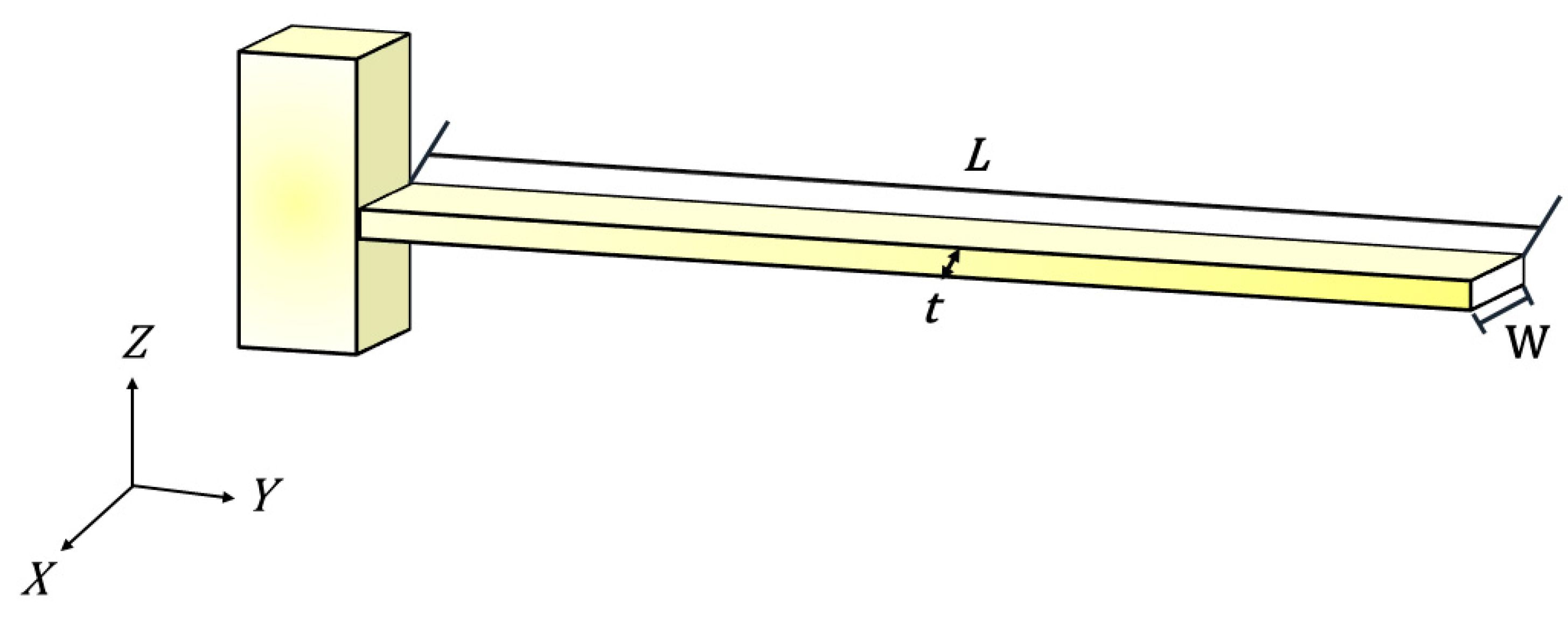
2]. Rectangular microcantilevers can be modeled as a planar beam that lies in a single plane (e.g., plane XY in Figure 1). The microcantilever lies in a plane parallel to a substrate where films to produce the microcantilever were grown, with the free tip capable of moving perpendicular to the substrate, such that the lateral in-plane motion of the free end would encounter more resistance [3].
Microcantilevers are extensively used as key components of physical, chemical, and biological sensors. The sensing application is based on the changes in bending (static mode) [4] or in resonance frequency (dynamic mode) [5] produced by the action induced by molecules or other materials adsorbed on the surface of the cantilever [6].
Although microcantilevers have been extensively explored for biosensing applications, several limitations persist in the existing literature. Most conventional designs rely on silicon (Si) or silicon-based materials (see Table 1), which, while widely available, exhibit moderate mechanical properties that constrain sensitivity—especially in dynamic operation modes. The relatively low Young’s modulus of Si limits the achievable resonant frequency, reducing the cantilever’s capacity to detect extremely small mass changes, such as those in the picogram range. Furthermore, many prior studies treat the actuator and cantilever design as separate entities, lacking a clear correlation between the piezoelectric actuator’s resonant frequency and the cantilever’s mechanical response. This disjointed approach leads to suboptimal energy transfer and reduced sensitivity. In addition, environmental damping and mechanical losses are often overlooked in simulation models, impacting predictive accuracy under real-world conditions.
This study introduces a unified and systematic design methodology that begins with optimizing the piezoelectric actuator and then designing the microcantilever based on the novel ultrananocrystalline diamond (UNCD) to match the actuator’s resonant frequency. This matching ensures efficient vibrational excitation. UNCD offers a higher Young’s modulus, shear modulus, and hardness and lower damping (characterized by Poisson’s ratio) compared to prior materials used for microcantilevers (Table 1). The unique UNCD properties enable enhanced resonant frequencies and superior sensitivity. The simulation framework incorporates both frequency and time domain analyses, including thermoelastic damping, to realistically predict quality factors and oscillation amplitudes. This integrated approach directly addresses the key challenges found in previous designs and provides a robust foundation for next-generation, high-sensitivity MEMS biosensors.
Table 1 summarizes the key mechanical properties of the materials previously used as bases for producing MEMS microcantilevers [7,8]. These include ultrananocrystalline diamond (UNCD) films, as developed by Auciello and colleagues [9,10,11,12], grown on Si substrates. UNCD exhibits the highest Young’s modulus among the listed materials. This implies that microcantilevers fabricated with UNCD are expected to exhibit superior sensitivity and mass resolution, especially when operating in dynamic mode.
For a cantilever operating in static mode, the sensing method relies on the flexural single bending of the beam (static mode) [4]. When a cantilever oscillates at its resonance frequency, induced by electrical or physical excitation, usually at its first resonance mode or eigenfrequency (dynamic mode) [5], the change in mass produced by the absorption of particles or molecules on the cantilever’s surface induces a change in the natural frequency [13].
Static mode is described by the Stoney Equation (1) [14],
Δ z = 3 1 ν L 2 E t 2 Δ σ
where Δ z is the bending amplitude of the microcantilever, Δ σ is the surface stress change, ν is the Poisson’s ratio, L is the length of the microcantilever, E is the Young’s modulus of the base material used to make the microcantilever, and t is thickness of the microcantilever. Thus, in operation mode, the sensing is based on the differential stress produced by the addition of particles or molecules on the surface of the cantilever and the consequent amplitude of the bending.
On the other hand, in dynamic mode, the sensing is related to the resonance frequency shift produced by the addition of particles to the surface of the vibrating microcantilever [9]. The resonance frequency, in terms of geometry and mechanical properties of the microcantilever, is given by Equation (2),
f n , 0 = ( β n ) 2 2 π t L 2 E 12 ρ
where f n , 0 is the natural resonance frequency of the microcantilever, with no damping for the n mode, β is a constant that appears during modal analysis, ρ is the density of the base material, and E, L, and t represent the same parameters as in Equation (1). For the first eigenfrequency, β 1 is 1.875, which originates from the solution of the Euler–Bernoulli beam theory, as shown in Equation (2) [3,15].
Furthermore, the mass sensitivity per unit mass of load on a rectangular microcantilever is given by Equation (3) [16],
d f 1 , 0 d m   f n , 0 2 m c
where mc is the total mass of the microcantilever. Equation (3) can be rewritten in terms of geometrical characteristics and material properties, replacing f n , 0 in Equation (3) with the parameters shown in Equation (2), giving Equation (4).
d f 1 , 0 d m   = 0.279 1 L 3 W ρ E 12 ρ
Equation (4) enables the calculation of the shift in the microcantilever vibration frequency in the first resonance mode f 1 , 0 produced by the addition of mass on the microcantilever. The frequency shift increases with the squared root of E and decreases with an increased density ρ of the beam’s material and an increased width W and length L of the cantilever.
Another important aspect to consider is the mass resolution, which is given by Equation (5) [14,16],
δ d f d m   = f n , 0 k B T B π k Q A 2
where δ d f d m   is defined as the minimum mass detectable by the minimum frequency shift, k B is the Boltzmann constant, T is the absolute temperature, B is the detection bandwidth, k is the spring constant of the microcantilever, Q is the quality factor, and A is the amplitude of the oscillation. Equation (5) is a general equation for micro-resonators for mass sensing. This equation shows that as the amplitude (A) of the oscillations decreases, the mass resolution of the resonator increases. On the other hand, the increase in resonant frequency (fn,0) increases the mass resolution.
As seen in Equations (4) and (5) the mechanical properties of the material play an important role in the mass sensitivity of microcantilevers. Both equations show that the Young’s modulus of a microcantilever’s material is a key factor for sensitivity and mass resolution, such that a large Young’s modulus increases the resonant frequency of the microcantilever, which, in turn, increases the mass resolution and sensitivity of a microcantilever-based biosensor.
Under dynamic mode operation, the actuation mechanism of the microcantilever plays a critical role. The most used methods include magnetic, electrostatic, thermoelectric, optothermal, and piezoelectric actuation [17].
Piezoelectric actuation offers several advantages, including suitability for miniaturization, high efficiency, absence of electromagnetic noise generation, and non-flammability [18]. Among piezoelectric materials, lead (Pb)–zirconium (Zr)–titanate (Ti) (PbZrxTi1-xO3 (PZT)) films are commonly used because they exhibit some of the highest piezoelectric coefficients and strong electromechanical coupling factors [19]. However, because of the toxicity of lead (Pb), alternative materials, such as aluminum nitride (AlN), zinc oxide (ZnO), and barium titanate (BaTiO3), have been explored for use in MEMS piezoelectric film applications.
AlN presents an electromechanical coupling coefficient of ~0.23, a high breakdown voltage (>1.2 × 10⁶ V∙cm−1), a high resistivity (~1012 Ω∙cm), a low loss tangent, and a high signal-to-noise ratio [20,21,22,23].
The purpose of the research presented in this article is to implement a methodology for studying the structural performance of UNCD microcantilevers actuated piezoelectrically, using AlN as the piezoelectric layer, for biosensing applications. The simulations were carried out using the commercially available software COMSOL Multiphysics Version 4. The results presented in this article provide valuable insight into the advantages of using UNCD-based microcantilevers for biosensing applications. The biosensor design is based on the structure proposed in reference [
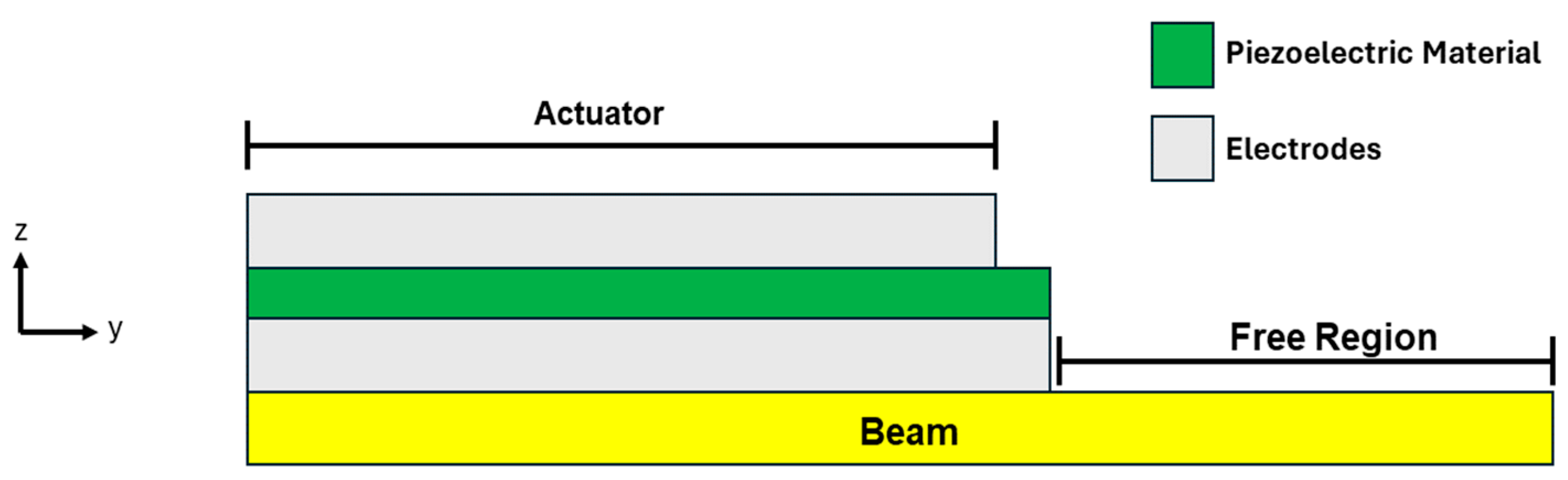
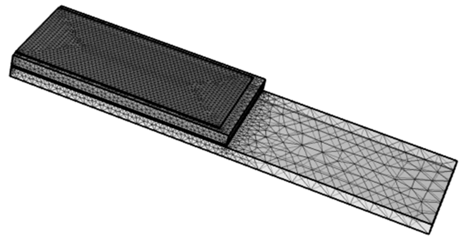
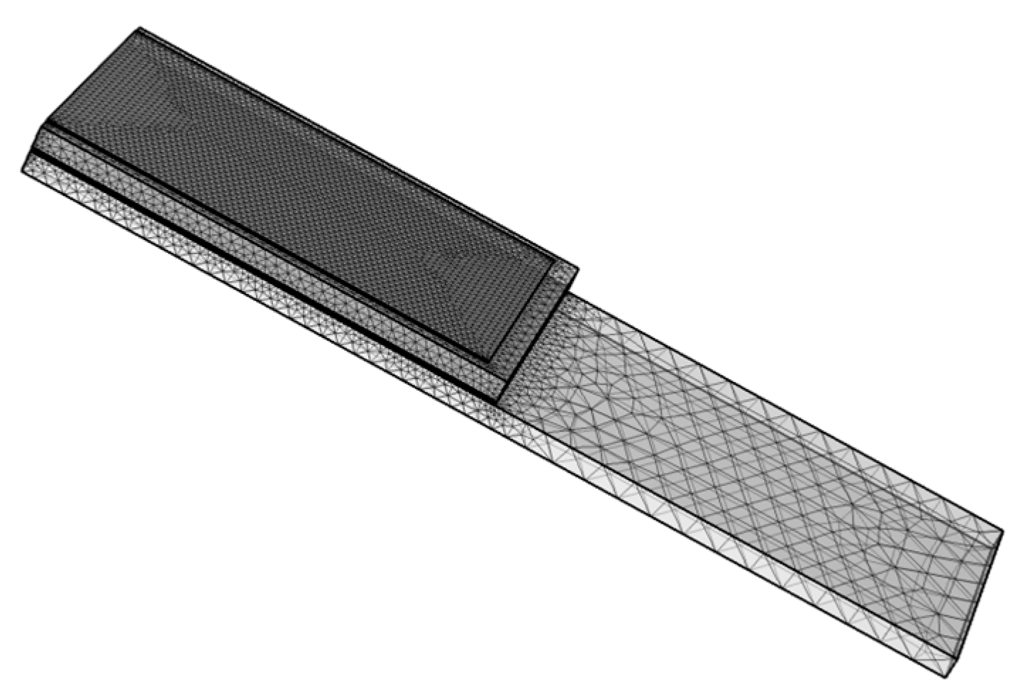
13], which features a stepped microcantilever with a portion of the beam left uncovered to allow particle adhesion on the UNCD surface, as shown in Figure 2. This uncovered region, referred to as the active area, can be functionalized for the selective binding of specific biomolecules, taking advantage of the excellent biocompatibility of the UNCD surface—an attribute demonstrated in multiple chapters of a recently published book edited by O. Auciello [24].
Additionally, a silicon (Si) microcantilever with the same design parameters was modeled to compare its performance with that of the UNCD-based microcantilevers.

2. Materials and Methods

The structure of the UNCD-based microcantilever, shown in Figure 2, was designed using COMSOL Multiphysics version 6.0. The design process was divided into two main stages. The first stage focused on analyzing the frequency response of the actuator alone. The second stage combined frequency and time domain analyses to determine the resonant frequency shift, oscillation amplitude (A), and quality factor (Q) of the integrated piezoelectric actuator–UNCD or Si beam system. The current model does not account for environmental damping or the influence of surrounding air. The simulations were conducted under vacuum conditions (≤10−3 Torr), where gas damping is negligible and the fluid is in the molecular regime. This simplification corresponds to a first step, first approximation approach aimed at determining the intrinsic structural parameters of the microcantilever. While measurements in future work will be carried out at atmospheric pressure, this initial modeling framework establishes a baseline that can be refined and improved by incorporating experimental data, including damping effects from air or liquid environments. All simulations were conducted at a fixed temperature of 298.15 K.

2.1. Design of the Actuator Structure

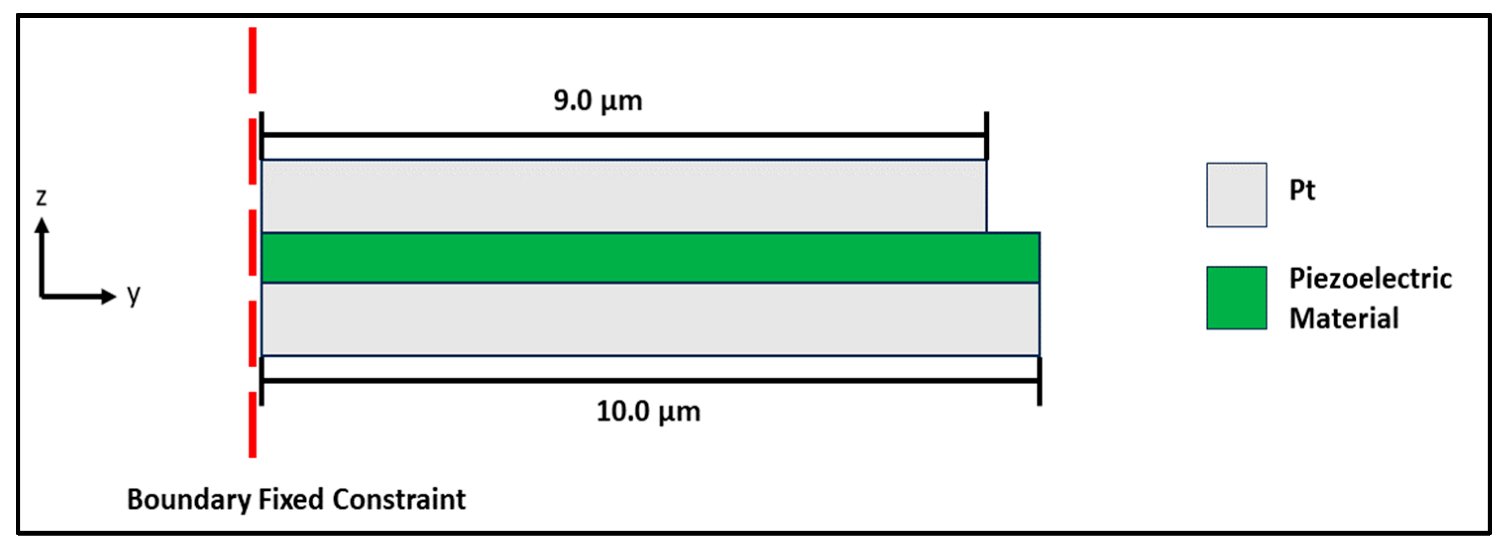
The metal/piezoelectric/metal actuation structure is designed as a capacitor-like configuration, consisting of an AlN film sandwiched between two platinum (Pt) electrodes, as shown in Figure 3. The top electrode measures 9.0 µm in length and 20 µm in width, while the bottom electrode is 10.0 µm long and 20 µm wide. Both electrodes have a thickness of 100 nm. The thickness of the AlN layer varies between 300 nm and 1000 nm.
The simulations in COMSOL Version 4 employed the Solid Mechanics and Electrostatics modules, as the primary objective was to determine the resonant frequency of the actuator. Thermoelastic effects were not included since this study focused on structural performance under idealized conditions, and thermal influences were assumed negligible at this stage to simplify the model and reduce the computational cost.
One end of the microcantilever was fixed while the other remained free, as indicated by the dotted red line in Figure 3. A relative tolerance of 0.001 was applied in the simulation. The generalized alpha solver of COMSOL Version 4 software was used, which operates similarly to the backward differentiation formula (BDF) solver but introduces a parameter called alpha to control numerical damping at higher frequencies. Displacement data were collected using an edge probe positioned at the tip of the actuator structure. The vertical displacement (in the z-direction, as shown in 
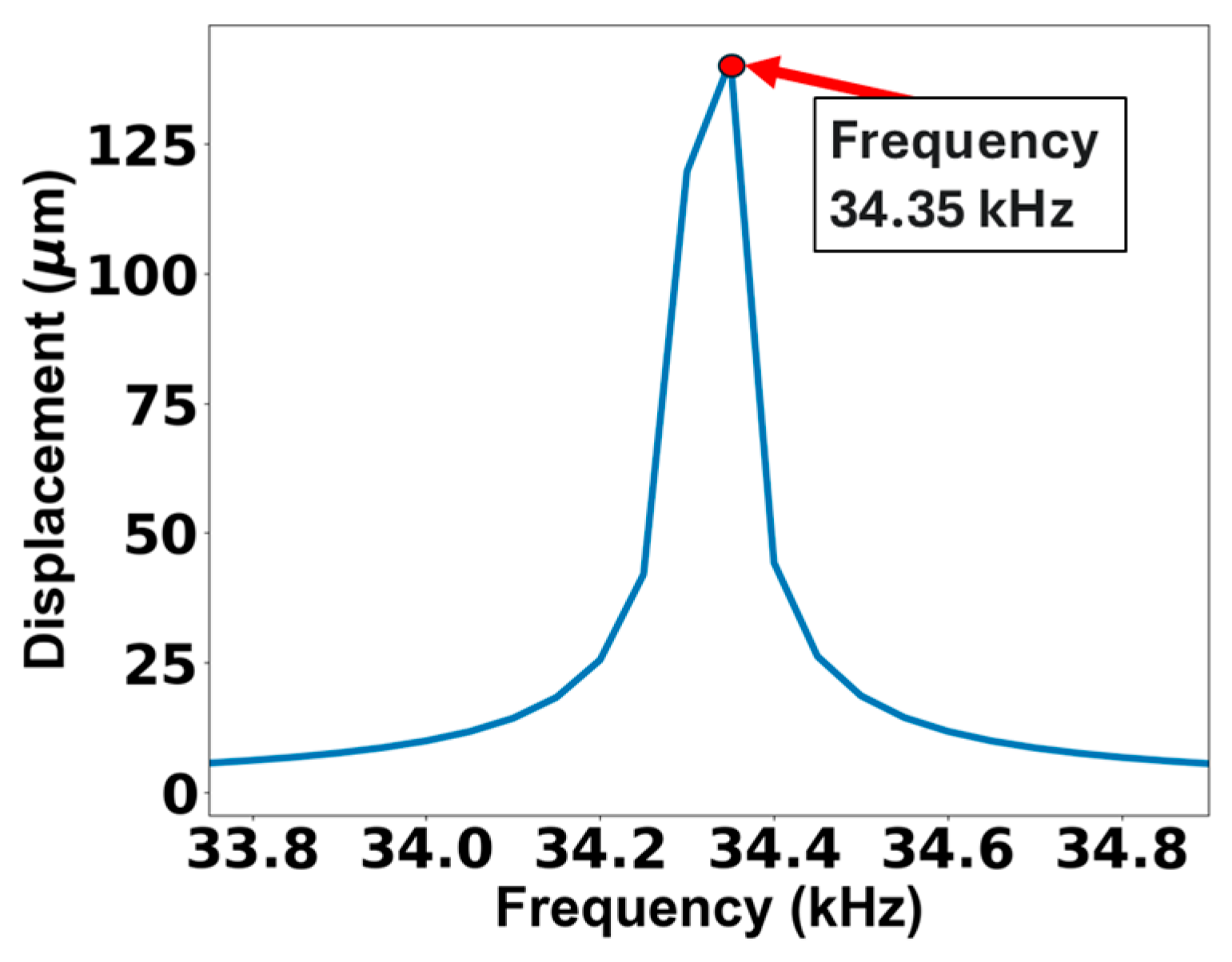
Figure 3) was used to estimate the resonant frequency.
It is important to acknowledge that the current model assumes a uniform mass distribution across the active surface of the microcantilever. While this simplification is useful for establishing baseline performance and sensitivity, it does not fully capture the localized nature of biomolecular adsorption that occurs in real biosensing applications. In practice, adsorbed mass is often concentrated near the tip of the cantilever, which can result in a more pronounced shift in resonant frequency. Modeling such non-uniform distributions would require additional assumptions about adsorption site, pattern, and density—parameters that depend on the specific biochemical environment and are not readily available without experimental input. Recognizing this limitation, future work will focus on incorporating spatially varying mass loads to improve the predictive accuracy of the simulations under more realistic sensing conditions.

2.2. Beam Eigenfrequency Matching

The purpose of optimizing the microcantilever beam is to standardize the design process. This step ensures that the initial beam length is determined using consistent criteria for both Si- and UNCD-based microcantilevers. The simulations involve an eigenfrequency optimization, where Equation (6) is used as the objective function [15].
f n , 0 f r 2
Equation (6) represents a user-defined objective function employed within the COMSOL Multiphysics Version 4 optimization module. Here, fr refers to the frequency used as a variable in the simulations. This objective function is commonly applied for eigenfrequency tuning.
This objective function (Equation (6)) represents the square of the relative error. The optimization was based on the minimization of the relative error using the BOBYQA (Bound Optimization By Quadratic Approximation) algorithm.

2.3. Coupled Simulation Actuator

Using the same methodology described in Section 2.1, the resonant frequency of the integrated piezoelectric actuator structure combined with either a UNCD or Si microcantilever was estimated. A mass of 1 picogram (pg), uniformly distributed across the surface of the UNCD or Si microcantilever, was then modeled using the Added Mass node in the Solid Mechanics module. This approach allows for the evaluation of the resonant frequency shift resulting from surface mass loading.
If the resonant frequency does not shift by at least 2 kHz, the microcantilever structure is modified by reducing the beam length. Shortening the beam increases its resonant frequency due to the corresponding reduction in mass. Additionally, since the sensitivity of a rectangular microcantilever (as shown in Equation (4)) is inversely proportional to the cube of its length (1/L3), decreasing the beam length significantly enhances the frequency shift and, consequently, the overall sensitivity.
After the optimization was finished, a more realistic mass distribution model was implemented to test the frequency response of the microcantilever. In this case, the mass was simulated by using the Added Mass Node but using a Gaussian distribution function to constrain the mass distribution to a certain area on the microcantilever. Equation (7) was used as the mass distribution function.
m =   1 × 10 15   kg ×   exp x x 0 2 + y y 0 2 r 2
where x and y represent the coordinates across the microcantilever beam, x0 and y0 are the coordinates where the center of the mass distribution is located, r is the variance in the mass distribution, which constrains the distribution to a certain region, and exp represents the Euler number. The maximum value of the mass distribution is reached exactly at the center of the region and decreases as the function takes a value away from the center. The value of r was set to 5 µm to evaluate the distribution at y0 40 µm, 30 µm, and 20 µm. The value of x0 was kept constant at 0 µm.

2.4. Time Domain Analysis

In the initial phase of the simulation, the frequency response of the microcantilever was determined. The next step involved estimating the quality factor (Q) and the oscillation amplitude. However, these parameters cannot be obtained directly from frequency domain analysis unless experimental data are incorporated into the numerical model to account for damping coefficients and mechanical losses.
In this section, the Heat Transfer in Solids module was implemented to account for thermoelastic damping, a critical effect in MEMS resonators. This module couples the heat transfer equations with the structural mechanics problem modeled using the Solid Mechanics module [25].
To induce physical motion in the microcantilever, an electrical pulse was applied to the electrodes that sandwich the AlN piezoelectric layer. The duration of the pulse was set to 100 times the period corresponding to the first resonant frequency, which was found to reliably ensure excitation of the fundamental vibrational mode.
The time steps for the electrical pulses were maintained at 1 × 10⁻⁸ s, with a strict relative tolerance of 0.001. The simulations employed the BDF solver with fixed time steps. To assess the influence of numerical damping introduced by the solver, the maximum order was varied between 2 and 5.
To compute the quality factor (Q), the general equation relating Q to the damping ratio was used, as defined in reference [26],
Q = 1 2 ζ
where ζ represents the damping ratio, which quantifies how quickly oscillations decay between successive cycles. It is defined in terms of the logarithmic decrement δ, as described in reference [25],
ζ = δ 4 π 2 + δ 2
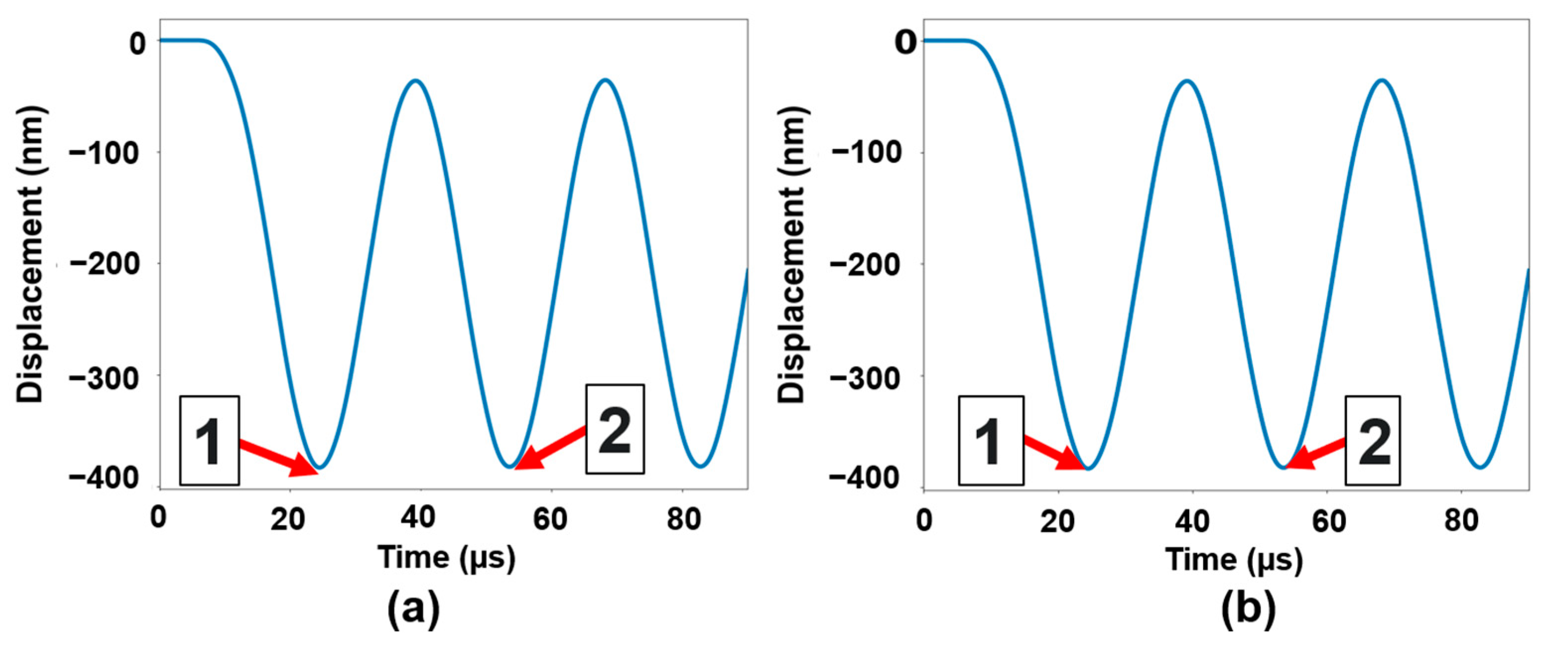
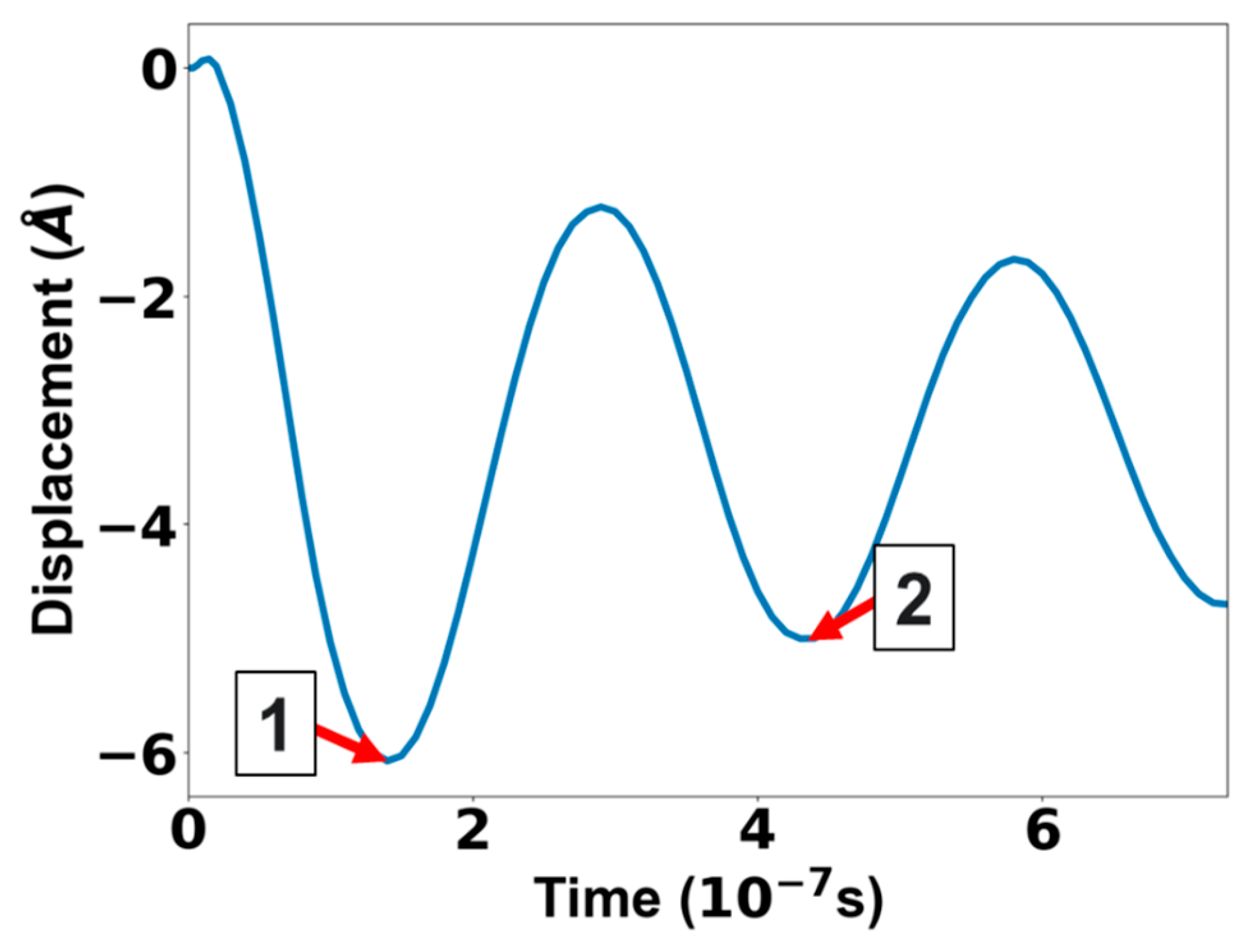
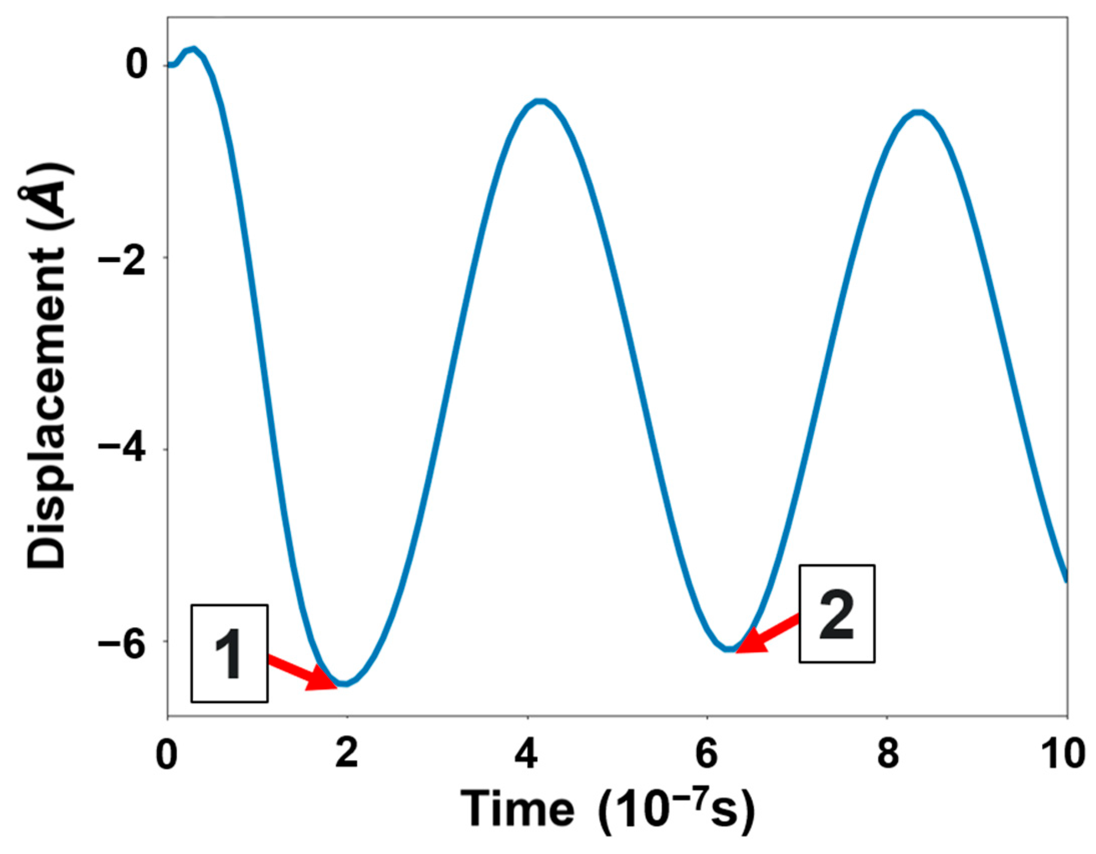
The logarithmic decrement is defined as natural logarithm of the ratio between the amplitudes of two consecutive pulse peaks z t n separated by n cycles of period T [25],
δ = 1 n ln z t n z ( t n + n T )
where z t n is the amplitude of the first pulse peak at t n and z ( t n + n T ) is the amplitude of the subsequent pulse peak, occurring after n cycles of period T.
The damping ratio was not directly inserted into the model; instead, it was estimated from the time-domain simulation by analyzing the decay of oscillation amplitude after a voltage pulse was applied. This indirect method allows for the calculation of Q without assuming arbitrary damping values, ensuring that the simulation reflects the natural damping behavior of the microcantilever under vacuum-like conditions.

2.5. Validation of the Models

Initially, the model was validated to prove its effectiveness for designing and analyzing the mechanical response of microcantilevers. The condition for validation of the model was that the microcantilever under test operated in the molecular regime where the damping of the surrounding fluid can be neglected.
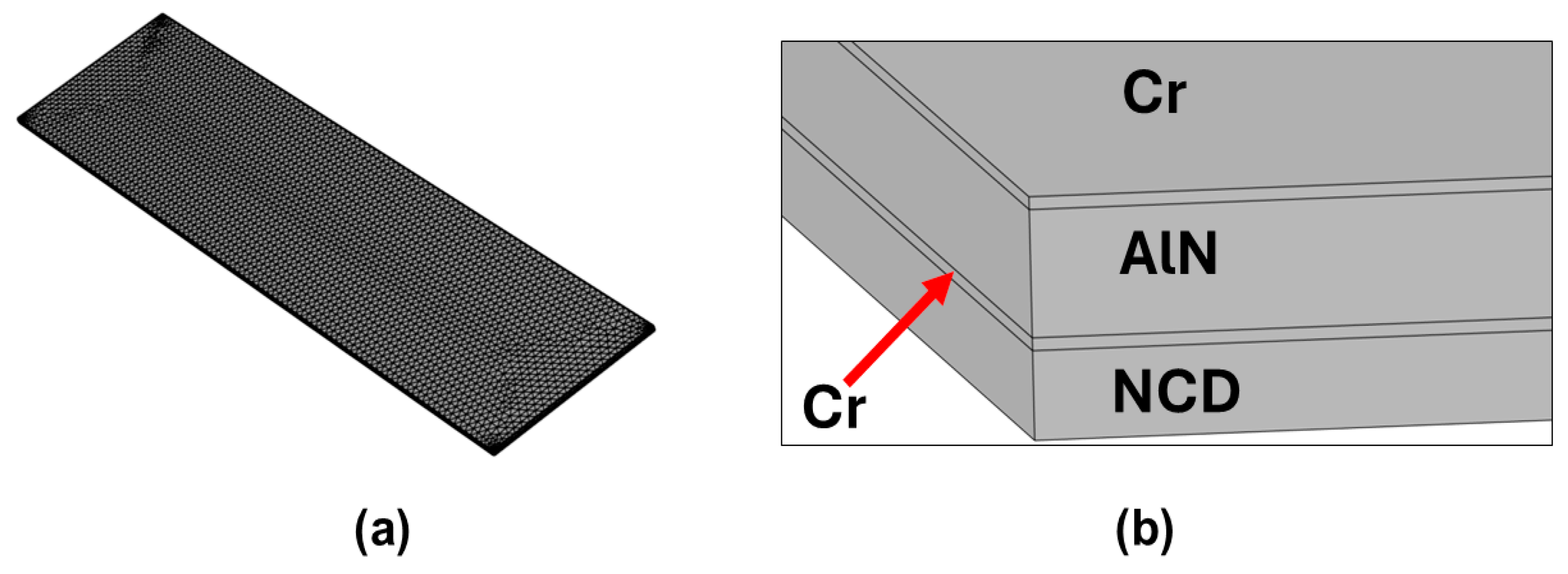
The integrated electrode/AlN/electrode layered structure on a nanocrystalline diamond (NCD) microcantilever, as reported in reference [27], was selected for comparison to validate the model developed in this study for the UNCD-based microcantilever. This choice is justified by the similarity in grain size between NCD (~10–20 nm) and UNCD (~3–5 nm). In reference [27], the characterization of the electrode/AlN/electrode/NCD microcantilever was performed using impedance analysis under relatively low vacuum conditions, specifically at a pressure of 200 mTorr.
Determining the first resonant frequency and its corresponding quality factor is essential for evaluating the accuracy and reliability of the models implemented in this study.

3. Results and Discussion

3.1. Validation of the Model: Metal/AlN/Metal Integration on a Nanocrystalline Diamond (NCD) Microcantilever

To validate the numerical model, an initial simulation was conducted based on the characterization of the NCD microcantilever reported in reference [27]. The goal was to compare the simulated results with the experimentally measured resonant frequency (from frequency domain analysis) and quality factor (from time domain analysis) for the first resonant mode.
The microcantilever beam described in reference [27] is 1 µm thick, with dimensions of 320 µm in length and 70 µm in width. The electrode and AlN films cover the entire surface of the microcantilever. Both the top and bottom electrodes are chromium (Cr) films deposited by sputtering. Since the thickness of the Cr films is not specified in the reference, it was assumed to be 100 nm for the purpose of simulation.
Using these values, the geometry of the microcantilever was modeled in COMSOL Multiphysics (Figure 4). For both frequency and time domain analyses, a free tetrahedral mesh consisting of 96,434 elements was employed (Figure 4a). The mesh was generated using COMSOL’s physics-controlled meshing algorithm with a fine mesh setting to ensure accurate resolution of structural and dynamic features. Figure 4b shows the layer structure of the cantilever.

3.1.1. Resonant Frequency Simulation

Using the methodology described in Section 2.1, the first resonant frequency was determined and compared to the value reported in reference [27]. The results are presented in Table 2. In the study corresponding to reference [27], the resonant frequency was obtained by identifying the resonant peak through impedance measurements shown in Figure 5
The displacement values of the microcantilever obtained through frequency domain analysis were found to be unusually high. This may be attributed to the mode superposition approach used in COMSOL’s frequency domain analysis, which can cause the natural frequency to trend toward infinity in the absence of damping [28]. A common way to address this issue is to incorporate experimentally measured damping coefficients or loss factors into the model. However, in this study, the quality factor of the structure was estimated by analyzing the decay of oscillations following the application of an electrical pulse to the microcantilever’s electrode films.
The results presented in Table 2 demonstrate the strong capability of the numerical model to accurately estimate the resonant frequency of the microcantilever.

3.1.2. Simulation of the Q Factor

Although a decrease in oscillation amplitude is generally not expected in undamped simulations, in this study, amplitude decay was observed because thermoelastic damping was explicitly included in the model. This was achieved by coupling the Heat Transfer in Solids module with the Solid Mechanics module in COMSOL Multiphysics. Thermoelastic damping arises because of the irreversible heat flow between the compressed and extended regions of the oscillating microcantilever, which leads to energy dissipation over time.
The decay in amplitude, therefore, reflects a physically meaningful damping mechanism, not just numerical damping from the solver. This inclusion allows for a more realistic estimation of the quality factor (Q) and validates the time domain analysis used in this study. The decay observed in the oscillation peaks (as shown in Figure 6a,b can thus be attributed primarily to the thermoelastic losses captured by the multiphysics coupling in the simulation.
Using the amplitude decay between two consecutive microcantilever oscillation peaks shown in Figure 6a,b and applying Equations (8)–(10), the quality factor (Q) was computed, as summarized in Table 3. Figure 6a corresponds to the simulation performed with a Backward Differentiation Formula (BDF) solver of maximum order 2, while Figure 6b shows the results using a BDF solver with maximum order 5.
The validation results suggest that using a lower maximum order for the BDF solver yields more accurate outcomes. This may be attributed to the fact that applying an electrical pulse excites not only the fundamental mode but also the higher-order vibrational modes of the microcantilever. A lower-order BDF solver introduces greater numerical damping, which helps suppress the influence of these higher modes, thereby enhancing the stability of the simulation and, in this case, improving the accuracy of the numerical model.
This observation is supported by the fact that the displacement at Point 1 in Figure 6a,b is identical, while the displacement at Point 2 differs between the two simulations, as shown in Table 4. Without numerical damping, both displacements at Point 2 should be equal. For our purpose, the order BDF solver introduces less numerical damping, which improves the Q factor estimation.

3.2. Frequency Response Analysis of the Actuator

The first step in designing the microcantilever involved determining the resonant frequency of the actuator. This frequency served as a reference for subsequent steps, where the goal is to match the eigenfrequency of the microcantilever beam to that of the actuator. This approach standardizes the design process, ensuring that any beam material—such as silicon (Si) or ultrananocrystalline diamond (UNCD)—is designed using the same initial parameters. Figure 7 shows the meshing and layer structure used for the simulations.
It is important to note that at nanoscale thicknesses, the mechanical properties of materials, such as Young’s modulus, residual stress, and fracture toughness, can vary significantly with film thickness because of surface effects, grain boundary evolution, and other size-dependent mechanical behaviors. This phenomenon has been well documented in the literature, particularly for piezoelectric and diamond-based thin films [29,30]. In the present study, COMSOL Multiphysics assumes constant mechanical properties for each material layer and does not inherently account for thickness-dependent variations unless they are explicitly defined by the user. To partially address this limitation, a parametric analysis was conducted across a range of film thicknesses to examine their influence on resonant frequency and structural response. The results were interpreted with an understanding of the potential deviations introduced by this modeling simplification. Future work will focus on integrating experimentally measured thickness-dependent material data to enhance simulation accuracy. However, for the purposes of this study, a first-order approximation was deemed sufficient to identify the key design parameters required for the fabrication of UNCD-based microcantilevers.
Table 5 shows the calculation of the resonance frequency for AlN layer thickness from 300 to 1000 nm. The width (20 µm) and length (10 µm) were kept fixed. As expected, the resonance frequency of the actuator increases as the thickness increases.
Based on the data presented in Table 5, the initial thickness of the AlN film was set to 300 nm, as this value provides a reasonable starting point for matching the eigenfrequency of the UNCD and Si microcantilever beams. This choice also offers greater flexibility in tuning the beam’s eigenfrequency during the design process. Selecting a thicker AlN film from the outset would result in a significantly higher resonant frequency, which, in turn, would require a shorter beam length to achieve frequency matching, as indicated by Equation (2).

3.3. Eigenfrequency Matching of the Beam of Microcantilevers

Eigenfrequency matching was initially explored for an actuator with a resonant frequency of 969 kHz, using a piezoelectric AlN layer with a thickness of 300 nm. The matching process involved estimating the required lengths of the UNCD and Si beams using Equation (2), which relates the beam length to its natural frequency. This approach provided a practical starting point for designing microcantilevers with resonant behavior aligned to that of the actuator.
To match the resonant frequency, an eigenfrequency optimization procedure was employed. This optimization considered the inclusion of a 100 nm thick titanium (Ti) layer deposited on top of the UNCD or Si beams, serving as an adhesion layer for the platinum (Pt) film used as the bottom electrode in the integrated Pt/AlN/Pt piezoelectric actuator structure. The Ti layer was modeled with the same lateral dimensions as the actuator schematic depicted in Figure 2, ensuring consistency in the structural configuration across all simulations.
The results of the simulations used to calculate the optimized lengths of the UNCD and Si beams—aimed at producing optimized microcantilevers for MEMS biosensor applications—are presented in Table 6. Length 1 refers to the initial estimate obtained directly from Equation (2), while Length 2 corresponds to the value derived from eigenfrequency optimization performed in COMSOL Multiphysics. Length 2 was adopted as the starting point for subsequent stages in the microcantilever design process.

3.4. AlN Actuator–Beam Integration

The first step involved assembling the Pt/AlN/Pt multilayer piezoelectric actuator structure with both Si and UNCD beams and evaluating whether the addition of mass across the active surface (the free region shown in Figure 2 of the cantilever produces a detectable resonant frequency shift. If no significant shift was observed, the beam length was reduced to increase sensitivity, following the relationship described by Equation (4).

3.4.1. Integration of the UNCD Beam

Using the design illustrated in Figure 8, the AlN layer thickness was varied from 300 nm to 1000 nm. As shown in Table 7, increasing the AlN thickness resulted in only modest gains in the resonant frequency shift. However, when the length of the UNCD beam was reduced to 40 µm—while keeping the AlN thickness at 1000 nm—the resonant frequency increased substantially from 1754.4 kHz to 3569.1 kHz. Although further shortening of the beam could enhance sensitivity by increasing the frequency shift, it would reduce the active area available for surface functionalization. This trade-off must be evaluated based on the specific requirements of the intended biosensing application.
Based on the results in Table 7, the configuration with a 1000 nm thick AlN layer and a UNCD beam length of 40 µm was selected for further analysis. To estimate the quality factor of this microcantilever, an electrical pulse was applied to its electrodes. The quality factor was then calculated using the amplitude decrement method, by measuring the displacement of the first two oscillation peaks—identified as Point 1 and Point 2 in Figure 9.
In Figure 9, it is important to note that the actuator–microcantilever system exhibits underdamped behavior, which is essential for accurately estimating the quality factor using this model. This is because Equations (8)–(10) are valid and reliable only for systems operating below the critical damping threshold.
The value of the quality factor (Q) is relatively low, (see Table 8) which is desirable for microcantilever-based biosensors. A lower Q factor ensures that smaller shifts in resonant frequency can be detected more effectively, enhancing the sensor’s sensitivity. Conversely, the amplitude of oscillations remains small (~5–6 Å), which is also advantageous for detecting low-mass biomolecules, as it minimizes noise and improves resolution.
Afterward, Equation (7) was used to add a mass at different places at the center of the beam, varying the y0 coordinate while keeping the x0 coordinate constant at 0 µm (see Figure 1 for the coordinate reference system). The shift in resonant frequency was measured and is presented in Table 9.

3.4.2. Integration of Si Beam

The same methodology used to integrate the AlN actuator film with the UNCD beam was applied to the Si beam, and the corresponding results are presented in Table 9. The optimization process for the actuator–Si microcantilever began directly with an AlN layer thickness of 1000 nm, based on the findings from the previous section, which demonstrated that this thickness enhances the resonance frequency shift of the microcantilever. To facilitate a direct comparison between the UNCD and Si microcantilevers under identical conditions, the optimized Si beam length of 37.7 µm was rounded up to 40 µm. Figure 10 shows the resulting structure for the Si microlever.
The displacement at the tip of the Si microcantilever is illustrated in Figure 11. The magnitude of displacement is comparable to that observed for the UNCD microcantilever, remaining within the same order. The quality factor (Q) of the Si microcantilever is slightly higher than that of its UNCD counterpart, (see Table 10) although still within the same range. Like the UNCD-based structure, the Si microcantilever exhibits underdamped oscillatory behavior, as shown in Figure 11.
Table 11 shows the results for the resonant frequencies and the resonant frequency shift for the Si microcantilever with the addition of 1 pg mass.
Following the same methodology for positioning a mass distribution function, Equation (7) was used to add a mass at different places at the center of the beam, varying the y0 coordinate while keeping the x0 coordinate constant at 0 µm (see Figure 1 for the coordinate reference system). The shift in resonant frequency was measured and presented in Table 12.

4. Conclusions

This work presented the theoretical design and modeling of high-sensitivity piezoelectrically actuated microcantilevers for biosensing applications. The modeling approach was validated against experimental data from nanocrystalline diamond (NCD) microcantilevers with integrated AlN piezoelectric actuators. Given the similarity in Young’s modulus between NCD and ultrananocrystalline diamond (UNCD), this system provided a suitable reference for validating both the frequency and time domain numerical models developed in this study. The simulated resonant frequencies and quality factors showed strong agreement with the experimental values, with deviations below 3%, likely due to numerical damping and microfabrication tolerances.
Following this validation, the models were applied to design UNCD-based and Si-based microcantilevers aimed at detecting an added mass of 1 picogram (pg) uniformly distributed over the cantilever’s active area. The design methodology centered on the integration of a Pt/AlN/Pt piezoelectric actuator, which served as the foundational component. The design process was standardized to enable scalability across different operational frequency ranges and target masses. By tuning the actuator’s resonant frequency and subsequently optimizing the beam length, the microcantilevers were tailored to exhibit measurable resonance frequency shifts in response to added mass.
Subsequently, a Gaussian distribution was used to confine the mass distribution to a certain area on the microcantilever. Three positions were used to observe the impact of the mass location on the resonant frequency shift of the UNCD and Si microcantilevers. It was observed that the resonant frequency shift decreases in comparison to when the mass is considered uniformly distributed on the surface. The resonant frequency shifts were reduced by 4 times.
Furthermore, the resonant frequency shift decreases as the mass distribution center is nearer the border of the piezoelectric actuator and increases as the mass distribution center moves towards the tip of the microcantilever. Both the UNCD and Si microcantilevers show slightly similar resonant frequency shifts upon positioning the mass distribution at the same points on the microcantilever (Table 9 and Table 12). Nonetheless, the relative trends between materials (UNCD vs. Si) and the overall design methodology remain valid. These results confirm the robustness of the modeling framework while acknowledging that precise mass distribution patterns would ultimately require experimental validation. Future work will further incorporate spatially resolved biomolecular adsorption data to improve accuracy.
Although environmental damping models, such as thermoacoustic effects, were not included in this phase of analysis, the structural response of the system was thoroughly characterized. This provided a critical first step in the design of reliable MEMS-based biosensors. Furthermore, the integration of COMSOL’s Heat Transfer in Solids module enabled the inclusion of thermoelastic damping, which allowed for physically realistic quality factor (Q) estimation through time domain simulations.
To evaluate biosensing performance, both the UNCD and Si microcantilevers were designed with identical geometries and actuator structures to isolate the impact of the base material. The results indicated that UNCD microcantilevers exhibit superior sensitivity and higher natural frequencies compared to their Si counterparts for the same active sensing area. This enhancement is attributed to the superior mechanical properties of UNCD, making it a strong candidate for next-generation biosensor platforms.
In terms of time domain analysis, simulations using a Backward Differentiation Formula (BDF) solver of orders 2 and 5 revealed that a lower solver order (2) produced results more consistent with the experimental Q values reported in [27]. This is likely due to the suppression of higher-order vibrational modes by the numerical damping introduced at lower solver orders. Attempts to implement the generalized alpha solver did not yield conclusive results, particularly for microcantilevers with natural frequencies approximately three orders of magnitude higher than the validation case. Further work is required to refine these damping models and improve simulation accuracy under high-frequency operation. Table 13 summarizes studies of cantilever simulations found in the literature.
Compared to previously reported methodologies for modeling microcantilever biosensors, the approach presented in this work offers a more comprehensive and experimentally validated framework by integrating both frequency and time domain finite element simulations using COMSOL Multiphysics. While analytical models, such as those by Akcali et al. [31] and Ansari and Cho [35], provide useful insights for initial estimations or device optimization, they are limited in their ability to account for complex material stacks and damping mechanisms. Stochastic models, like those by Snyder et al. [33] and Paul et al. [34], focus on noise and thermal fluctuations, but they do not provide structural performance evaluation under piezoelectric actuation. In contrast, the study described in this article not only models a realistic multilayer actuator structure (Pt/AlN/Pt) integrated on ultrananocrystalline diamond (UNCD), but it also validates the model using published experimental data on nanocrystalline diamond (NCD) microcantilevers. This dual-domain, experimentally benchmarked simulation strategy allows for accurate estimation of key performance indicators, such as resonant frequency shifts and quality factor (Q), making it more suitable for guiding the design of next-generation MEMS biosensors with picogram-level sensitivity.
In conclusion, this study demonstrates a robust simulation framework for designing and analyzing piezoelectrically actuated UNCD-based microcantilevers. The methodology is validated, scalable, and adaptable, laying a solid foundation for the development of MEMS biosensors capable of detecting extremely small mass changes with high precision. Future work will focus on the fabrication and experimental testing of the proposed devices to validate their biosensing performance under realistic conditions. One critical aspect will be the experimental investigation of how the mechanical properties of thin films—particularly UNCD and AlN—vary with thickness at the nanoscale, as such variations can significantly influence resonant behavior. Additionally, the effect of atmospheric pressure on the quality factor and sensitivity will be studied by simulating and testing device performance under different environmental damping conditions, including operation in air and vacuum. This next phase will not only verify the predictive accuracy of the numerical models but also provide insight into optimizing the microcantilever structure for real-world biochemical detection applications.

Author Contributions

Conceptualization, V.D., O.A. and E.d.O.; methodology, V.D.; software, V.D.; validation, V.D., O.A. and E.d.O.; formal analysis, V.D.; investigation, V.D.; resources, O.A.; data curation, V.D.; writing—original draft preparation, V.D.; writing—review and editing, O.A. and E.d.O.; visualization, V.D.; supervision, O.A. and E.d.O.; project administration, O.A.; funding acquisition, V.D., O.A. and E.d.O. All authors have read and agreed to the published version of the manuscript.

Funding

This research was funded by SENACYT-Panamá, grant number FDI22-048, SNI-AIP (E. de Obaldía), SENACYT Doctoral Scholarship BIDP-I-2019-015 (D. Villarreal), and by funds from the University of Texas at Dallas, provided for the Distinguished Endowed Chair Professor position of O. Auciello.

Institutional Review Board Statement

Not applicable.

Informed Consent Statement

Not applicable.

Data Availability Statement

Data is contained within the article.

Acknowledgments

The authors acknowledges CIDESI Querétaro (Departamento de Ciencias y Microtecnologías) for support during the development of the process for fabrication and design, and the collaboration with the software COMSOL Multiphysics Version 4.

Conflicts of Interest

The authors declare no conflicts of interest.

References

  1. Mouro, J.; Pinto, R.; Paoletti, P.; Tiribilli, B. Microcantilever: Dynamical response for mass sensing and fluid characterization. Sensors 2020, 21, 115. [Google Scholar] [CrossRef]
  2. Zhang, H.; Yang, S.; Zeng, J.; Li, X.; Chuai, R. A genosensor based on the modification of a microcantilever: A Review. Micromachines 2023, 14, 427. [Google Scholar] [CrossRef] [PubMed]
  3. Liu, C. Foundations of MEMS, 1st ed.; Pearson Prentice Hall: Upper Saddle River, NJ, USA, 2006. [Google Scholar]
  4. Berger, R.; Delamarche, E.; Lang, H.P.; Gerber, C.; Gimzewski, J.K.; Meyer, E.; Guntherodt, H.J. Surface Stress in the Self-Assembly of Alkanethiols on Gold. Science 1997, 276, 2021–2024. [Google Scholar] [CrossRef]
  5. Thundat, T.; Warmack, R.J.; Chen, G.Y.; Allison, D.P. Thermal and ambient-induced deflections of scanning force microscope cantilevers. Appl. Phys. Lett. 1994, 64, 2894–2896. [Google Scholar] [CrossRef]
  6. Manvi, M.; Swamy, K.M. Microelectronic materials, microfabrication processes, micromechanical structural configuration based stiffness evaluation in MEMS: A review. Microelectron. Eng. 2022, 263, 111854. [Google Scholar] [CrossRef]
  7. AZO Materials, Silicon Nitride (Si3N4) Properties and Applications. Available online: https://www.azom.com/article.aspx?ArticleID=53 (accessed on 2 September 2023).
  8. Shackelford, J.; Alexander, W. CRC Materials Science and Engineering Handbook; Thurd Edition: Toulouse, France, 2000. [Google Scholar]
  9. Auciello, O.; Sumant, A.V. Status review of the science and technology of ultranano-crystalline diamond (UNCDTM) films and application to multifunctional devices. Diam. Relat. Mater. 2010, 19, 699–718. [Google Scholar] [CrossRef]
  10. Auciello, O.; Pacheco, S.; Sumant, A.A.; Gudeman, C.; Sampath, S.; Datta, S.; Carpick, R.W.; Adiga, V.P.; Ma, Z.; Carlisle, J.A.; et al. Are diamonds a MEMS’ best friend? IEEE Microw. Mag. 2007, 8, 61–75. [Google Scholar] [CrossRef]
  11. Auciello, O.; Aslam, D.M. (Invited Review) Review on advances in microcrystalline, nanocrystalline and ultrananocrystalline diamond films-based micro/nano-electromechanical systems technologies. J. Mater. Sci. 2021, 56, 7171–7230. [Google Scholar] [CrossRef]
  12. Espinosa, H.D.; Prorok, B.C.; Peng, B.; Kim, K.H.; Moldovan, N.; Auciello, O.; Carlisle, J.A.; Gruen, D.M.; Mancini, D.C. Mechanical properties of ultrananocrystalline diamond thin films relevant to MEMS/NEMS devices. Soc. Exp. Mechnics 2003, 43, 256–268. [Google Scholar] [CrossRef]
  13. Liu, D.; Shu, W. Microcantilever biosensors: Probing biomolecular interactions at the nanoscale. Curr. Org. Chem. 2011, 15, 477–485. [Google Scholar] [CrossRef]
  14. Rast, S.; Wattinger, C.; Gysin, U.; Meyer, E. Dynamics of damped cantilevers. Rev. Sci. Instrum. 2000, 71, 2772–2775. [Google Scholar] [CrossRef]
  15. Passian, A.; Tundat, T. Microcantilever Sensors, Encyclopedia of Materials: Science and Technology, 2nd ed.; 2011; pp. 1–6. Available online: https://www.sciencedirect.com/science/article/pii/B9780080431529022624 (accessed on 7 September 2023).
  16. Incaviglia, I.; Herzog, S.; Fläschner, G.; Strohmeyer, N.; Tosoratti, E.; Müller, D.J. Tailoring the sensitivity of microcantilevers to monitor the mass of single adherent living cells. Nano Lett. 2023, 23, 588–596. [Google Scholar] [CrossRef] [PubMed]
  17. Martínez Silva, V.F. Diseño y caracterización de un biosensor en modo de resonancia para la detección de microoorganismos patógenos. Ph.D. Thesis, Instituto Politécnico Nacional, Centro de Investigación en Computación, Ciudad de México, Mexico, 2012. [Google Scholar]
  18. Uchino, K. Piezoelectric actuators 2006: Expansion from IT/robotics to ecological/energy applications. J. Electroceram. 2006, 20, 301–311. [Google Scholar] [CrossRef]
  19. Bobic, J.D.; Vijatovic Petrovic, M.M.; Stojanovic, B.D. Review of the most common relaxor ferroelectrics and their applications. In Magnetic, Ferroelectric, and Multiferroic Metal Oxides; Elsevier: Amsterdam, The Netherlands, 2018; pp. 233–249. [Google Scholar] [CrossRef]
  20. Mahmoodi Nasrabadi, H.; Mahdavi, M.; Soleymaniha, M.; Moheimani, S.O.R. High resolution atomic force microscopy with an active piezoelectric microcantilever. Rev. Sci. Instrum. 2022, 93, 073706. [Google Scholar] [CrossRef]
  21. Signore, M.A.; Rescio, G.; De Pascali, C.; Iacovacci, V.; Dario, P.; Leone, A.; Quaranta, F.; Taurino, A.; Siciliano, P.; Francioso, L. Fabrication and characterization of AlN-based flexible piezoelectric pressure sensor integrated into an implantable artificial pancreas. Sci. Rep. 2019, 9, 17130. [Google Scholar] [CrossRef]
  22. Algieri, L.; Todaro, M.T.; Guido, F.; Mastronardi, V.; Desmael, D.; Qualfieri, A.; Giannini, C.; Sibillano, T.; De Vittorio, M. Flexible Piezoelectric Energy-Harvesting Exploiting Biocompatible AlN Thin Films Grown onto Spin-Coated Polyimide Layers. ACS Appl. Energy Mater. 2018, 1, 5203–5210. [Google Scholar] [CrossRef]
  23. Iqbal, A.; Mohd-Yasin, F. Reactive sputtering of aluminum nitride (002) thin films for piezoelectric applications: A review. Sensors 2018, 18, 1797. [Google Scholar] [CrossRef]
  24. Auciello, O. Ultrananocrystalline Diamond Coatings for New Generation High-Tech and Medical Devices; Cambridge Publisher: Cambridge, UK, 2022. [Google Scholar]
  25. Brimmo, A.T.; Hassan, M.I.; Chatterjee, A.N. Pressure dependent quality factor of micron scale single mass cantilever energy harvesters. AbuDhabi 2015. Available online: https://www.researchgate.net/publication/283149040_Pressure_Dependent_Quality_Factor_of_Micron_Scale_Single_Mass_Cantilever_Energy_Harvesters (accessed on 26 August 2024).
  26. Lee, J.H.; Lee, S.T.; Yao, C.M.; Fang, W. Comments on the size effect on the microcantilever quality factor in free air space. J. Micromech. Microeng. 2007, 17, 139–146. [Google Scholar] [CrossRef]
  27. Mortet, V.; Soltani, A.; Talbi, A.; Pobedinaskas, P.; Haenen, K.; de Jaeger, J.-C.; Pernod, P.; Wagner, P. Proceedings of the Eurosensors XXIII conference AlN on nanocrystalline diamond piezoelectric cantilevers for sensors/actuators. Procedia Chem. 2009, 1, 40–43. [Google Scholar] [CrossRef]
  28. Sonnerling, H. Frequency Response of Mechanical Systems, COMSOL Multiphysics Blog. Available online: https://www.comsol.com/blogs/frequency-response-of-mechanical-systems (accessed on 9 April 2024).
  29. Cammarata, R.C. Surface and interface stress effects in thin films. Progress. Surf. Sci. 1994, 46, 1–38. [Google Scholar] [CrossRef]
  30. Espinosa, H.D.; Prorok, B.C.; Fischer, M. A methodology for determining mechanical properties of freestanding thin films and MEMS materials. J. Mech. Phys. Solids 2003, 51, 47–67. [Google Scholar] [CrossRef]
  31. Akcali, P.; Kelleci, K.; Ozer, S. Design and Simulation of the Microcantilever Biosensor for MITF Antigen and D5 Monoclonal Antibody Interaction: Finite Element Analysis and Experimental Validation. Curr. Protein Pept. Sci. 2024, 25, 256–266. [Google Scholar] [CrossRef]
  32. Louarn, G.; Cuenot, S. Finite Element Modelling of Micro-cantilevers Used as Chemical Sensors. arXiv 2009, arXiv:0904.3999. Available online: https://arxiv.org/abs/0904.3999 (accessed on 1 June 2025).
  33. Snyder, P.; Joshi, A.; Serna, J.D. Modeling a Nanocantilever-Based Biosensor Using a Stochastically Perturbed Harmonic Oscillator. Int. J. Nanosci. 2013, 13, 1450011. [Google Scholar] [CrossRef]
  34. Paul, M.R.; Clark, M.T.; Cross, M.C. The Stochastic Dynamics of Micron and Nanoscale Elastic Cantilevers in Fluid: Fluctuations from Dissipation. arXiv 2006, arXiv:cond-mat/0605035. Available online: https://arxiv.org/abs/cond-mat/0605035 (accessed on 1 June 2025).
  35. Ansari, M.Z.; Cho, C. High S/N Ratio Slotted Step Piezoresistive Microcantilever Designs for Biosensors. Sensors 2013, 13, 4088–4101. [Google Scholar] [CrossRef]
Figure 1. Structure of a microcantilever with one free end, where L is the length, W is the width, and t is the thickness of the beam.
Applsci 15 06902 g001
Figure 2. Base structure of the step microcantilever. The z – y plane refers to the coordinates in Figure 1. This design was proposed in reference [11].
Applsci 15 06902 g002
Figure 3. Geometric model of the piezoelectric actuation-based structure for the microcantilever biosensor. The dotted line represents the fixed boundary conditions.
Applsci 15 06902 g003
Figure 4. (a) NCD microcantilever geometry (mesh) and (b) material layers included in the integrated metal/AlN/metal piezoelectric actuation-based structure.
Applsci 15 06902 g004
Figure 5. Microcantilever displacement vs. frequency simulation for the metal/AlN/metal layered structure on the NCD microcantilever.
Applsci 15 06902 g005
Figure 6. Microcantilever displacement vs. time for the metal/AlN/metal/NCD-integrated microcantilever, (a) using BDF with maximum order 2 and (b) using the BDF solver with maximum order 5. The red arrows show the points used for the calculation of the Q value.
Applsci 15 06902 g006
Figure 7. (a) Mesh across the actuator (b) layers that compose the actuator.
Applsci 15 06902 g007
Figure 8. Free tetrahedral mesh across the cantilever. This mesh corresponds to an AlN film thickness of 1000 nm and a UNCD beam length of 40 µm. The region of the actuator exhibits more elements, as necessary for piezoelectricity modeling.
Applsci 15 06902 g008
Figure 9. Displacement of the tip of the UNCD microcantilever after applying a rectangular electrical pulse of 0.5 V amplitude to the electrodes encapsulating the AlN layer. Points 1 and 2 are used for the damping calculation.
Applsci 15 06902 g009
Figure 10. Free tetrahedral mesh across the cantilever. This mesh corresponds to an AlN film thickness of 1000 nm and a Si beam length of 40 µm. The region of the actuator exhibits more elements, as necessary for piezoelectricity modeling.
Applsci 15 06902 g010
Figure 11. Displacement of the tip of the Si microcantilever after applying a rectangular electrical pulse of 0.5 V to the electrodes encapsulating the AlN layer. Points 1 and 2 are used for the damping calculation.
Applsci 15 06902 g011
Table 1. Comparison of mechanical properties of Si, SiC, and Si3N4 [7,8], with UNCD [9,10,11,12].
PropertySiSiCSi3N4UNCD
Young’s Modulus (GPa)130450166–297916–980
Shear Modulus (GPa)8014965.3–127577
Hardness (kg/mm2)10003500800–305010,000
Fracture Strength (GPa)1.05.20.18–0.655.3
Poisson’s Ratio0.22–0.2780.183–0.1920.23–0.280.07
Density (kg/m3)2329321031703500
Table 2. Results of the first resonant frequency validation. The plus sign on the percent difference is used to indicate that the simulated resonant frequency was overestimated.
Reference [27] Resonant Frequency (kHz)Simulated Resonant Frequency (kHz)Percent Difference from Experiment [27]
(%)
33.3534.35+3.00
Table 3. Results of the quality factor Q for the first resonant frequency. The minus sign in the percent difference indicates that the value is underestimated with the experimentally measured Q for the first resonant frequency of the microcantilever reported in [27].
Reference Quality Factor Q (kHz)BDF Solver Maximum OrderSimulated Quality Factor Q (kHz)Percent Difference (%) from Experiment Ref. [27]
165021647.4−1.57
165051466−11.1
Table 4. Displacement of the microcantilever at Points 1 and 2.
Order of BDF SolverDisplacement at Point 1
(nm)
Displacement at Point 2 (nm)
2−383.16−382.43
5−383.16−382.34
Table 5. First resonant frequency of the actuator for the AlN film thickness in the range of 100–1000 nm.
Thickness (nm)f (kHz)
100443.1
200686.3
300969
4001280
5001591
7502467.3
10003385.3
Table 6. Length of the Si and UNCD beams for MEMS microcantilever-based biosensors. Length 1 is the length calculated using Equation (2), and Length 2 is obtained using Eigen-frequency Optimization.
MaterialLength 1 (µm)Length 2 (µm)
Si37.739.8
UNCD52.853.3
Table 7. Resonant frequency shift for UNCD microcantilevers. The added mass is 1 pg for each simulation. The bold values indicate the optimized value for the UNCD microcantilever.
AlN Film Thickness (nm)Beam Length (µm)Number of ElementsResonant Frequency (kHz)Resonant Frequency Shift (kHz)
30053.3101,3481286.10.6
50053.3110,2181434.60.6
75053.3128,2711609.50.7
100053.3131,4491754.40.8
100040.0131,1113569.12.4
Table 8. Displacement of the tip and Q calculation for the UNCD microcantilever.
Displacement at Point 1 (Å)Displacement at Point 2 (Å)Number of ElementsQ
−6.0786−5.0056140,76016.18
Table 9. Resonant frequency shift (Hz) for a mass distribution function described by Equation (7), with radius r = 5 µm, positioned at y0 on the UNCD beam while keeping x0 at 0 µm.
y0 Coordinate (µm)Resonant Frequency Shift (Hz)
40600
30400
20100
Table 10. Displacement of the tip and the calculated value of Q for the UNCD microcantilever.
Displacement at Point 1 (Å)Displacement at Point 2 (Å)Number of ElementsQ
−6.4494−6.0859108,07054.16
Table 11. Resonant frequency shift for Si microcantilevers. The added mass is 1 pg. The bold values indicate the value for the Si microcantilever used for the analysis.
AlN Film Thickness (nm)Beam Length (µm)Number of ElementsResonant Frequency (kHz)Resonant Frequency Shift (kHz)
30037.781,1751926.02.0
100037.799,5762882.43.2
10004087,3472446.52.4
Table 12. Resonant frequency shift (Hz) for a mass distribution function described by Equation (7), with radius r = 5 µm, positioned at y0 on the Si beam while keeping x0 at 0 µm.
y0 Coordinate (µm)Resonant Frequency Shift (Hz)
40600
30300
20100
Table 13. Comparison of other modeling approaches for microcantilever simulations.
Modeling
Methodology
Representative StudyDescription
Analytical ModelingAkcali et al. (2024) [31]Used classical beam theory to estimate resonant frequency shifts due to biomolecular interactions. Analytical results were validated through finite element analysis and experiment
Finite Element Analysis (FEA)Louarn and Cuenot (2009) [32]Simulated multilayered cantilevers using FEA to determine resonant frequencies and mode shapes with high accuracy, beyond the limitations of analytical models.
Stochastic ModelingSnyder et al. (2013) [33]Modeled cantilever dynamics as stochastically perturbed harmonic oscillators to account for random adsorption and noise, key for low-mass biosensing.
Thermodynamic and Stochastic AnalysisPaul et al. (2006) [34]Used fluctuation–dissipation theory and thermodynamic modeling to understand the noise-limited performance of cantilevers in fluid environments.
Hybrid Analytical–FEAAnsari and Cho (2013) [35]Integrated analytical beam theory and FEA for piezoresistive cantilever optimization, achieving improved signal-to-noise ratio and sensitivity.
Validated FEM + Time Domain (This Work)This work Developed a validated FEM model in COMSOL for piezoelectrically actuated UNCD microcantilevers. Combined frequency and time domain analysis, and benchmarked results with experimental data from AlN/NCD cantilevers reported in the literature.
Disclaimer/Publisher’s Note: The statements, opinions and data contained in all publications are solely those of the individual author(s) and contributor(s) and not of MDPI and/or the editor(s). MDPI and/or the editor(s) disclaim responsibility for any injury to people or property resulting from any ideas, methods, instructions or products referred to in the content.

