Article

Double-Borehole Superimposed Effect of a New Non-Explosive Directional Rock-Breaking Method

1
School of Mines, China University of Mining and Technology, Xuzhou 221116, China
2
State Key Laboratory of Explosion Science and Safety Protection, Beijing Institute of Technology, Beijing 100081, China
3
National Key Laboratory of Uranium Resources Exploration-Mining and Nuclear Remote Sensing, Beijing 100029, China
4
State Key Laboratory of Geomechanics & Deep Underground Engineering, China University of Mining and Technology, Beijing 100083, China
5
School of Resources and Safety Engineering, Central South University, Changsha 410083, China
6
Guangxi China Tin Group Stock Co., Ltd., Liuzhou 545006, China
7
School of Civil Engineering and Architecture, Anhui University of Science and Technology, Huainan 232001, China
8
School of Resources and Geosciences, China University of Mining and Technology, Xuzhou 221116, China
9
College of Environmental Science and Engineering, Ocean University of China, Qingdao 266100, China
*
Author to whom correspondence should be addressed.
Appl. Sci. 2025, 15(12), 6805; https://doi.org/10.3390/app15126805
Submission received: 28 April 2025 / Revised: 8 June 2025 / Accepted: 11 June 2025 / Published: 17 June 2025
(This article belongs to the Special Issue Advanced Technology in Geotechnical Engineering)

Abstract

Due to the difficulty of creating directional fractures efficiently and accurately with existing non-explosive rock-breaking methods, a directional fracturing technique utilizing a coal-based solid waste expansive agent, termed the instantaneous expansion with a single fracture (IESF), has been developed. IESF can generate high-pressure gases within 0.05–0.5 s and utilize gas pressure to achieve directional rock fragmentation. The rock-breaking mechanisms under double-borehole conditions of conventional blasting (CB), shaped charge blasting (SCB), and IESF were studied by theoretical analysis, numerical simulation, and in situ test. The gas pressure distribution within directional fractures of IESF was determined, and the crack propagation criterion between double-borehole was established. Numerical simulation results indicated that the stress distribution in CB was random. SCB exhibited tensile stress of −10.89 MPa in the inter-borehole region and −8.33 MPa on the outer-borehole region, while IESF generated −14.47 MPa and −12.62 MPa in the corresponding regions, demonstrating that stresses generated between adjacent boreholes can be superimposed in the inter-hole region. In CB, strain was concentrated along main fractures. SCB exhibited strains of 7 mm and 8 mm in the shaped charge direction, while non-shaped charge directions showed a strain of 1.5 mm. For IESF, strain in the shaped charge direction measured 6 mm, compared to 1 mm in non-shaped charge directions, resulting in superior directional fracture control. In situ test results from Donglin Coal Mine demonstrated that IESF can form superior directional rock-breaking efficacy compared to both CB and SCB, with the average crack rates of 95.5% by IESF higher than 85.0% by SCB. This technique provides a non-explosive method that realizes precise control of the direction of cracks while avoiding the high-risk and high-disturbance problems of explosives blasting.

1. Introduction

To achieve desired rock fragmentation outcomes in practical applications, typically it is necessary that the synergistic interaction of multi-borehole acts collectively on the rock mass. Therefore, it is imperative to investigate the superimposed effect of double-borehole fracturing to elucidate the varying patterns of stress-strain fields during practical rock fragmentation and their impact on crack propagation. Explosive blasting is a commonly used method of rock destruction at present, and has been widely used in engineering practice because of its characteristics of high power, low cost, and simple operation [1,2]. In order to control the effect of explosive blasting, the energy release law can be changed by using a slit-oriented tube [3,4], so as to achieve the effect of directional blasting [5,6,7]. The stress-strain fields of double-borehole blasting are different from that of single hole blasting. Different from the single-borehole loading of conventional blasting of explosives, the double-borehole loading will cause the superposition of stress waves, making the radial cracks formed between the two holes easy to completely break [8]. Under the condition of hydrostatic in situ stress, the detonation cracks propagating perpendicular to the direction of the hole line are more likely to be inhibited by in situ stress. When the in situ stress is low, although the low uncoupling coefficient can promote the crack propagation significantly, it also increases the bifurcation density and expanding range of the crack, increases the damage range of the surrounding rock mass, and is not conducive to the pre-crack forming. With the increase of in situ stress, the superimposed effect of stress waves decreases, and the crack propagation length between boreholes decreases as the stress level increases, and the cracks mainly expand along the direction of the maximum principal stress, which further affects the slit cutting effect between double holes [9,10]. The time delay between double-borehole loadings also affects inter-borehole fracture development. When the time delay is less than the arrival time of detonation energy at the second borehole, the number of blast-induced cracks between the boreholes increases with longer time delays [11]. At the same time, delayed blasting between two holes is limited by the hole spacing, and delayed blasting has a greater effect on the superposition of tensile stresses and requires a higher degree of accuracy in the delay [12,13]. The influence of different joint angles between the double holes on the propagation of inter-hole cracks is significantly different. When the joints are perpendicular to the inter-hole line, the blocking effect on cracks is the smallest, with the angle decreasing, the blocking effect gradually increases. The blocking effect is the strongest at 30°, and the direction of crack extension is guided when the angle continues to decrease [14]. In addition, the presence of empty holes at suitable spacing also acts as a guide for crack propagation between the two holes [15]. The stress field at the fracture tip during shaped charge blasting is altered by the presence of neighboring boreholes, which enhances the process of directional extension of the fracture [16]. For multi-borehole shaped charge blasting in the same section of the detonation conditions, the distance between the boreholes is the main factor affecting the fractures between the boreholes; the appropriate distance between the boreholes through the superposition of the stress can effectively promote fracture penetration, improving the effect of directional rock fragmentation [17,18]. Crack propagation between two holes of shaped charge blasting is still dominated by tensile stresses, and the explosive gas is the main driving force [19]. Slit charge blasting relies on the slit-oriented tube to control the direction of energy transmission to realize the directional rock fragmentation [20]. To realize interconnected fractures in double-borehole slit charge blasting, it is necessary to ensure overlap of damage zones between boreholes, which requires regulating the superimposed stress fields between energy-focused boreholes by adjusting borehole spacing [21]. In the case of cracks between double holes, unequal lengths of cracks, distance from the free surface, and height difference between cracks can lead to the formation of hook cracks, which affects the penetration between cracks [22].
However, explosive blasting is prohibited in certain scenarios due to its significant disturbance and safety risks [23,24]. Therefore, non-explosive methods are needed for the destruction of rocks. Hydraulic fracturing is often used as a non-explosive rock-breaking method instead of explosives to accomplish fracturing rock. The crack propagation patterns in multi-borehole hydraulic fracturing are predominantly influenced by in situ stress and rock mechanical properties. Increased in situ stress induces fracture zone contraction and width enlargement, while a higher elastic modulus promotes elongated and narrow fracture geometries [25], and crack propagation directions are significantly affected by the direction of maximum principal stress as well as principal stress interpolation [26,27]. In multi-borehole hydraulic fracturing conditions, the initiation pressure of inner boreholes is consistently higher than that of outer boreholes. Additionally, the initiation pressures of all three fracturing boreholes exhibit a significant increase with larger fracture borehole spacing. When the spacing between fracturing boreholes is small, both outer boreholes generate hydraulic fractures perpendicular to the orientation of the minimum horizontal principal stress, while the central borehole produces hydraulic fractures parallel to this orientation. These fractures extend and interconnect, forming complex fracture networks. In contrast, larger borehole spacing results in relatively independent fractures [28]. The competition between the boundary stress and the internal stress of the holes controls the fracture growth patterns, and the reduction of the boundary stress difference exacerbates the stress concentration between the holes, causing planar fractures formed by a single borehole to evolve into spiral fractures interconnecting two boreholes [29]. Fractures created between multiple holes can expand directionally along the borehole connecting lines, but fractures formed outside the multiple holes fail to expand in that direction [30]. Hydraulic fracturing is difficult to generate directional fractures as expected, so directional hydraulic fracturing is often required to control the direction of the fractures [31]. Directional hydraulic fracturing of a multi-borehole is significantly affected by the principal stress. The rock damage process is dominated by tensile damage, and the deformation damage is most intense at the center line of the holes, which forms a “strip-like” fracture surface along the direction of the borehole layout [32]. However, the directional hydraulic fracturing is significantly influenced by in situ stress, resulting in suboptimal directional efficacy [33,34]. Although directional hydraulic fracturing can control the direction of fracture propagation within a certain range by grooving the hole wall, the direction of fracture propagation will re-orientate as the differential stress states and the distance increases [35]. Moreover, the fracture surface generated by the directional hydraulic fracturing is usually extending radially along the radial direction of the borehole at the groove [36], which is perpendicular to the fracture surface that extends along the axis of the borehole in the shaped charge direction by shaped charge blasting. Therefore, it is difficult to replace shaped charge blasting with directional hydraulic fracturing. Due to the above factors, the development of novel non-explosive directional rock-breaking methodologies is urgently required.
In this context, a new method for directional rock fragmentation, called instantaneous expansion with a single fracture (IESF), has been proposed using a coal-based solid waste expansive agent. IESF generates directional fractures within a short timeframe, combining the directional efficacy and rock-breaking power of shaped charge blasting while avoiding the high risks associated with explosive blasting. However, the superimposed effects of double-borehole loading in IESF remains insufficiently studied. This paper carries out an investigation of this problem and performs a comparative analysis of rock-breaking mechanisms between IESF, conventional blasting (CB), and shaped charge blasting (SCB).

2. Methodology

2.1. Structure and Working Principle of IESF

The IESF is a directional rock-breaking technique that utilizes coal-based solid waste materials as the primary raw material, instantaneously inducing two-dimensional fracture planes in rock masses. The main structure of IESF (Figure 1) consists of four parts: a slit-oriented tube, coal-based solid waste expansive agent, coupling medium, and electrical initiating device.
The slit-oriented tube is equipped with two rows of energy-gathering holes symmetrically positioned at diametrically opposite ends of its circular cross-section. Each row of holes is arranged equally spaced along the axial direction of the tube. The primary components of the coal-based solid waste expansive agent include: oxidizer A: 30–40%, combustible/reducing agent B: 30–65%, additive C: 5–30%, catalyst D: 0.5–3%, and binder E: 1.25%. The coupling medium serves to transmit rock-breaking energy and can use air, water, or sand-gravel mixtures as materials. The electric initiating device comprises a fuse, wire, and a current emitter, where the current emitter activates the coal-based solid waste expansive agent through the fuse.
When employing IESF, the expansion agent is electrically initiated, undergoing rapid phase transition from solid particles to high-pressure gases within 0.05–0.5 s. A mass of 1 g of the expansion agent generates approximately 300 mL of gases, which is used to fracture the rock mass through high gas pressure. These high-pressure gases form “point-like” energy-gathered jets through the energy-gathering holes on the slit-oriented tube in each borehole, resulting in uniform compressive stress in non-slotted directions and tensile stress along the slotted orientation.
This mechanism drives directional tensile fracture initiation along the slotted direction on the borehole wall. Following fracture initiation, the fractures are instantaneously filled with high-pressure gases, inducing stress-superimposed effects between the double boreholes. Under the tensile action of these gases, the fractures propagate directionally until connecting adjacent slotted fracture planes generated from neighboring boreholes, forming interconnected fracture surfaces that achieve directional fracture planes (Figure 2). Thus, IESF precisely controls the direction of crack propagation by means of a slit-oriented tube.

2.2. The Theoretical Model of Double-Borehole Directional Rock-Breaking by IESF

2.2.1. Spatial Distribution Pattern of High-Pressure Gas Pressure Generated by IESF

Following rock fragmentation by IESF, the resulting two-dimensional fracture planes exhibit significantly greater length than width, with the fracture width progressively decreasing from the near-surface to deeper regions. Consequently, the fracture cross-section can be approximated as symmetrical triangular profiles, as shown in Figure 3.
Then, the volume of the cavity inside the borehole and fracture is
V = π r 2 L + l ( t ) d L
where V is the volume of the cavity inside the borehole and fracture, m3. r is the radius of the borehole, m. L is the length of the charge section inside the borehole, m. l ( t ) is the fracture depth as a function of time t , m. d is the width of the fracture in the borehole wall, m.
The volume of gas generated by IESF can be viewed as a linear function of the mass of the expansive agent, so there is
k = V 0 m
where k is the IESF combustion coefficient per unit time, m3·s/kg. V 0 is the volume of gas generated after the reaction at room temperature and pressure, m3. m is the mass of expansive agents involved in the reaction per unit time, kg/s.
The volume of gas generated at room temperature and pressure can be expressed by the ideal gas equation. For the high-temperature and high-pressure gases generated by IESF in the borehole, the van der Waals equation [37] is used to express the relationship between the gas pressure and volume, and the pressure in the pore can be expressed as
( p g + a n 2 V 2 ) ( V n b ) p 0 V 0 = n R T n R T 0
where p g is the gas pressure in the borehole, MPa. a is the parameter for measuring intermolecular gravity. b is the sum of the volumes contained in 1 mole of the molecule itself. n is the number of moles. p 0 is the standard atmospheric pressure, MPa. T is the post-reaction temperature in the borehole, °C. T 0 is the temperature corresponding to the combustion coefficient k , °C.
Substituting Equations (1) and (2) into Equation (3) can be obtained by
p g ( t ) = T p 0 k m t T 0 [ π r 2 L + l ( t ) d L n b ] a n 2 V 2
Due to the influences of fracture surface roughness, surrounding rock permeability, and gas flow velocity, a pressure gradient inevitably exists in the gas pressure distribution within fractures. However, fracture surfaces in different rock types exhibit significant variations in roughness and permeability. The results of fracture propagation are influenced by the action of the gas within the crack as a whole, rather than the individual action of one point within the crack. Therefore, the calculation of the distribution of gas pressure is simplified considering the above situations. For computational simplification, this gradient can be approximated as uniform attenuation. Referencing Nilson et al.’s research on gas flow characteristics within fractures [38], the gas pressure distribution is expressed as
p ( x , t ) = p g ( t ) [ 1 x r l ( t ) ]
where p ( x , t ) is the gas pressure distribution in the fracture, MPa. p g ( t ) is the gas pressure in the borehole at the moment t , MPa. r is the radius of the borehole, m.
Substituting Equation (4) into Equation (5) can be obtained by
p ( x , t ) = T p 0 k m t T 0 [ π r 2 L + l ( t ) d L n b ] a n 2 V 2 [ 1 x r l ( t ) ]

2.2.2. Crack Propagation Criterion of IESF

The stress intensity factor at the fracture tip is the superposition of stress intensity factors induced by in situ stress and gas pressure. Therefore, the mechanical model for crack propagation in rock fragmentation by IESF can be decomposed into a fracture tip extension model under in situ stress and a crack propagation model with gas pressure effects in the absence of in situ stress.
The relationship between the in situ stress ( σ 1 and σ 3 ) and σ x , σ y , τ x y on the fracture surface can be expressed as
σ x = σ 1 + σ 3 2 + σ 1 σ 3 2 cos 2 θ σ y = σ 1 + σ 3 2 σ 1 σ 3 2 cos 2 θ τ = σ 1 σ 3 2 sin 2 θ
where θ is the angle between the fracture surface and the x-direction. For the points on the fracture surface, since the fracture length is much larger than the fracture width, the value of θ is extremely small and can be approximated as θ 0 , then there is σ y = σ 3 . For points on the crack surface, σ y is in the same direction as the gas pressure, so the total stress on points on the crack surface is
σ t = p ( x , t ) + σ 3
where l is the fracture length. F 1 is related to σ 1 / σ 3 and l / r d .
The stress intensity at the fracture tip induced by gas pressure can be expressed as
K I σ = F σ r r + l [ p x , t + σ 3 ] d x π r + l
where F σ is the shape correction factor, which varies with fracture size and shape, geometric parameters of the fracture structure, and boundary conditions.
Substituting Equation (6) into Equation (9) can be obtained by
K I σ = F σ r r + l T p 0 k m t T 0 [ π r 2 L + l ( t ) d L n b ] a n 2 V 2 σ 3 [ 1 x r l ( t ) ] d x π r + l
The dynamic fracture toughness of a rock during crack propagation can be expressed as [39,40]
K I c d = ( c R v a ) ( c R 0.75 v a ) K I c
where c R is the Rayleigh wave velocity of the rock material, v a is the crack extension velocity, and K I c is the static fracture toughness of the rock. When the fracture is unaffected by adjacent ones, the crack propagation condition requires that the stress intensity factor at the fracture tip is not less than the dynamic fracture toughness of the rock,
K I σ K I c d
It can be also obtained as
F σ r r + l T p 0 k m t T 0 [ π r 2 L + l ( t ) d L n b ] a n 2 V 2 σ 3 [ 1 x r l ( t ) ] d x π r + l ( c R v a ) ( c R 0.75 v a ) K I c
When the fracture expands to the point affected by the extension of neighboring ones, the strength factor at the fracture tip needs to be added to K I σ , so
K I d = K I σ + K I σ
Theoretically, the stress intensity factor at fracture tips is identical to adjacent ones, and its effect on extension K I σ is K I σ for n times, so
K I σ = n K I σ
where n 1 .
Then, the criterion for the occurrence of fracture tip extension is
K I d = K I σ + K I σ K I c d
It also be also obtained as
K I d = ( 1 + n ) K I σ K I c d
Therefore, the criterion is finally obtained by
( 1 + n ) F σ r r + l T p 0 k m t T 0 [ π r 2 L + l ( t ) d L n b ] a n 2 V 2 σ 3 [ 1 x r l ( t ) ] d x π r + l ( c R v a ) ( c R 0.75 v a ) K I c

2.3. The Numerical Model Calculation Principle of IESF

2.3.1. The Numerical Calculation Theory of IESF

In order to characterize the uneven distribution of rock composition and structure in different directions, the Weibull distribution function [41] was used to describe the mesoscopic unit mechanical parameters of rock.
φ ( s , m ) = m s 0 ( s s 0 ) m 1 exp ( s s 0 ) m
where s is the mesoscopic unit mechanical parameters, including modulus of elasticity, Poisson’s ratio, etc. s 0 is statistical averages of the mesoscopic unit mechanical parameters. m is used to characterize the distribution pattern of mesoscopic unit mechanical parameters and is taken as 5.
When the maximum principal stress of the meso-element reaches its tensile strength, the maximum tensile stress criterion is used as the damage threshold criterion, which can be expressed as
F 1 σ 1 σ t = 0
where σ 1 is the maximum principal stress. σ t is the uniaxial tensile strength.
For the damage of meso-element under uniaxial compression or shear stress, the Mohr–Coulomb criterion is adopted as the damage threshold criterion, which can be expressed as
F 2 σ 1 1 + sin φ 1 sin φ σ 3 σ c = 0
where σ 3 is the minimum principal stress. φ is the internal friction angle. σ c is uniaxial compressive strength.
The elastic modulus of rock mass can be expressed as
E = 1 D E
where E and E are the elastic modulus of the rock before and after damage, respectively. D is the damage variable, which can be expressed as [42,43]
D =    0         F 1 < 0 , F 2 < 0    1 ε t / ε 1 n     F 1 = 0 , d F 1 / d t > 0 1 ε c / ε 3 n     F 2 = 0 , d F 2 / d t > 0      
where ε t and ε c are the maximum tensile principal strain and maximum compressive principal strain corresponding to tensile damage and shear damage of the element, respectively. ε t and ε c are the first principal strain and the third principal strain, respectively. n is a coefficient of unit damage evolution, and is 2.
When IESF breaks the rock, the high energy gas pressure [44] generated by IESF is
P g = P g 0 m s 0 s s 0 m - 1 exp s s 0 m
where P g is the gas pressure generated by IESF. P g 0 is the constant related to the peak pressure. s is the loading step. s 0 is the constant related to the loading step. m is the shape parameter of homogeneity.
When an explosive is used to break rock, the rock mass is subjected to the action of both stress wave and blast-induced gas. The loading equation of the stress wave is [45]
P d = P 0 exp g a t t 0 sin 4 π 1 + t / t 0
where P d is the stress under the action of stress wave. P 0 is the peak stress, which can be calculated by 140 e 6 Q 3 / 2 ; Q is the amount of explosive. g a is the explosive attenuation rate. t 0 is the loading time. The loading equation of blast-induced gas is shown in Equation (24).

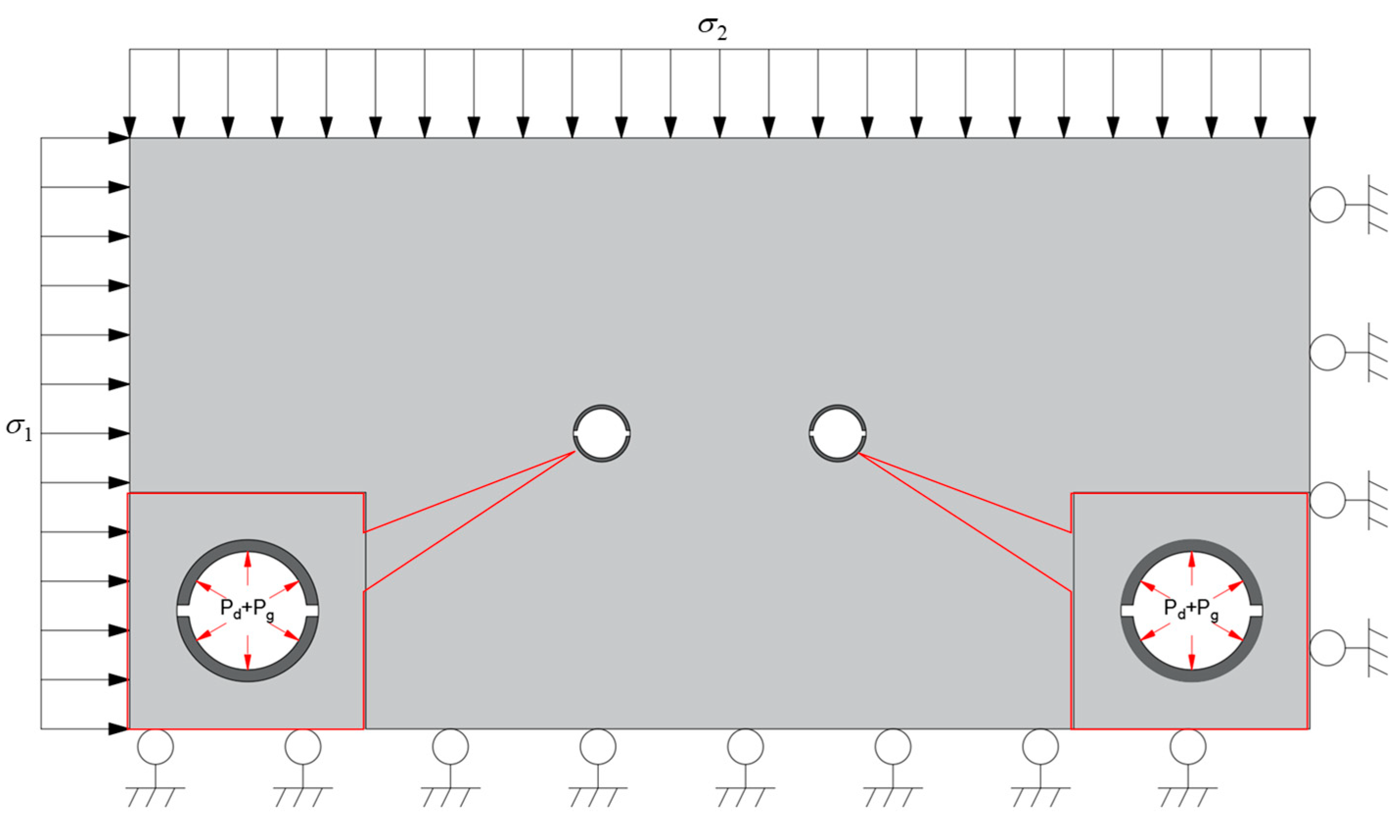
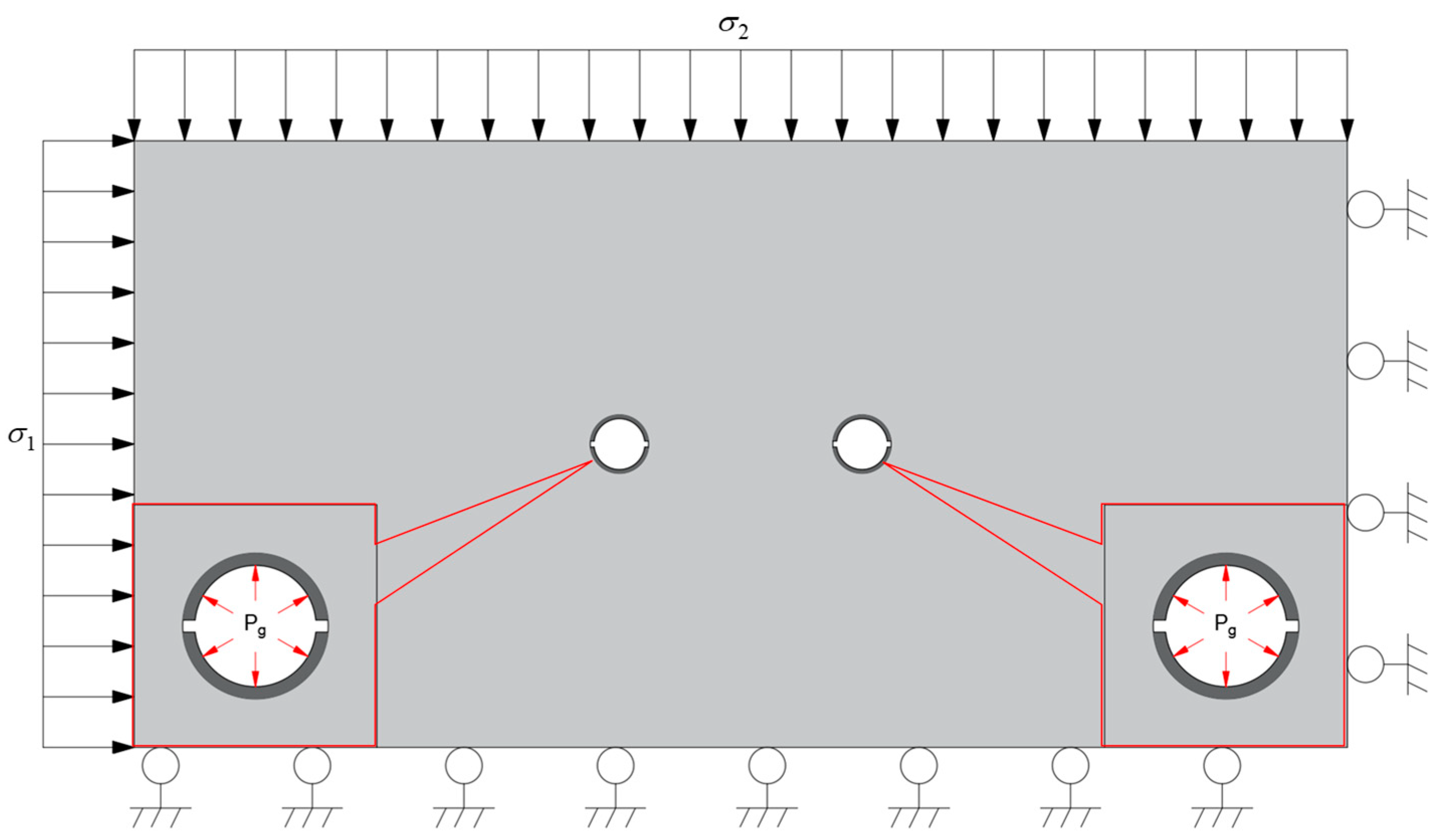
2.3.2. Numerical Model of Double-Hole Fracture

To research the difference of the rock-breaking performance by CB, SCB, and IESF, numerical models for these three scenarios were established as shown in Figure 4, Figure 5, and Figure 6, respectively. All models shared identical dimensions of 2 m × 1 m, each containing double boreholes with uniform parameters: 48 mm borehole diameter and 400 mm inter-borehole spacing. All three models shared identical rock physical and mechanical parameters. An in situ stress of 15 MPa was imposed on the left boundary and an in situ stress of 11 MPa was imposed on the top boundary, while displacement constraints were applied to the bottom and right boundaries.
In regards to the distinction between the three types of simulation, the stress wave generated by CB directly acted on the hole wall with the blast-induced gas, and the stress wave generated by SCB acted on the hole wall through the slit-oriented tube with the blast-induced gas, while IESF fractured the rock mass through the high gas pressure generated by itself without the action of a detonation wave. For CB and SCB, the loading sequence comprised stress waves from Steps 0–50 by Equation (25), followed by blast-induced gas pressure form Steps 51–100 by Equation (24), with loading profiles illustrated in Figure 7. High-pressure gases generated by IESF were loading throughout Steps 0–100, as shown in Figure 8. The slit-oriented tubes used by IESF share standardized geometric parameters with SCB: 42 mm inner diameter, 48 mm outer diameter, with 8 mm diameter of energy-gathering holes.

2.4. In Situ Test Scheme of IESF

The in situ test was conducted in the intake airway of the W1-406 working face at Donglin Coal Mine, Tiemei Group (Figure 9). Adjacent to the W1-405 working face, the coal seam exhibits a thickness of 2.5–3.2 m, an average dip angle of 6°, and a burial depth ranging from 251 m to 301 m. The test section roadway features an immediate roof composed of mudstone, and a main roof consisting of glutenite.
The layout of slotted boreholes in the experimental section is illustrated in Figure 10. These boreholes were positioned on the roadway roof near the working face side, inclined at 15° from the vertical direction. Each borehole had a total length of 9 m, with the charge section of IESF extending 6.5 m within the glutenite layer, and the sealing section extending 2.5 m through both mudstone and glutenite strata. All of the following tests employed double-borehole configurations, with a 50 mm borehole diameter and 400 mm inter-borehole spacing.
In situ experiments were conducted using three different roof-cutting methods: CB, SCB, and IESF. IESF and SCB both utilized 42 mm outer diameter slit-oriented tubes, while CB was without slit-oriented tubes. The outer diameter of the explosives was 32 mm. The charge structures for each method are illustrated in Figure 11.
As shown in Figure 11a, CB employed a five-stage charge configuration from the borehole bottom to the opening of the borehole, with segment lengths of 1.5 m, 1.5 m, 1.5 m, 1.5 m, and 0.5 m, corresponding to the respective explosive charges of 1000 g, 1000 g, 800 g, 800 g, and 200 g, resulting in a total charge of 3800 g per borehole. SCB utilized slit-oriented tubes with identical stage lengths and charge quantities as CB in Figure 11b. For the IESF in Figure 11c, the borehole was also divided into 5 sections; the length of each IESF from the bottom of the hole to the opening of the hole was 1.5 m, 1.5 m, 1.5 m, 1.5 m, and 0.5 m, the charge mode was spaced charging, and the amount of the charge was 875 g, 875 g, 700 g, 700 g, 175 g, respectively. The amount of the single-hole charge was 3325 g in total.

3. Results

3.1. Numerical Simulation Results of IESF

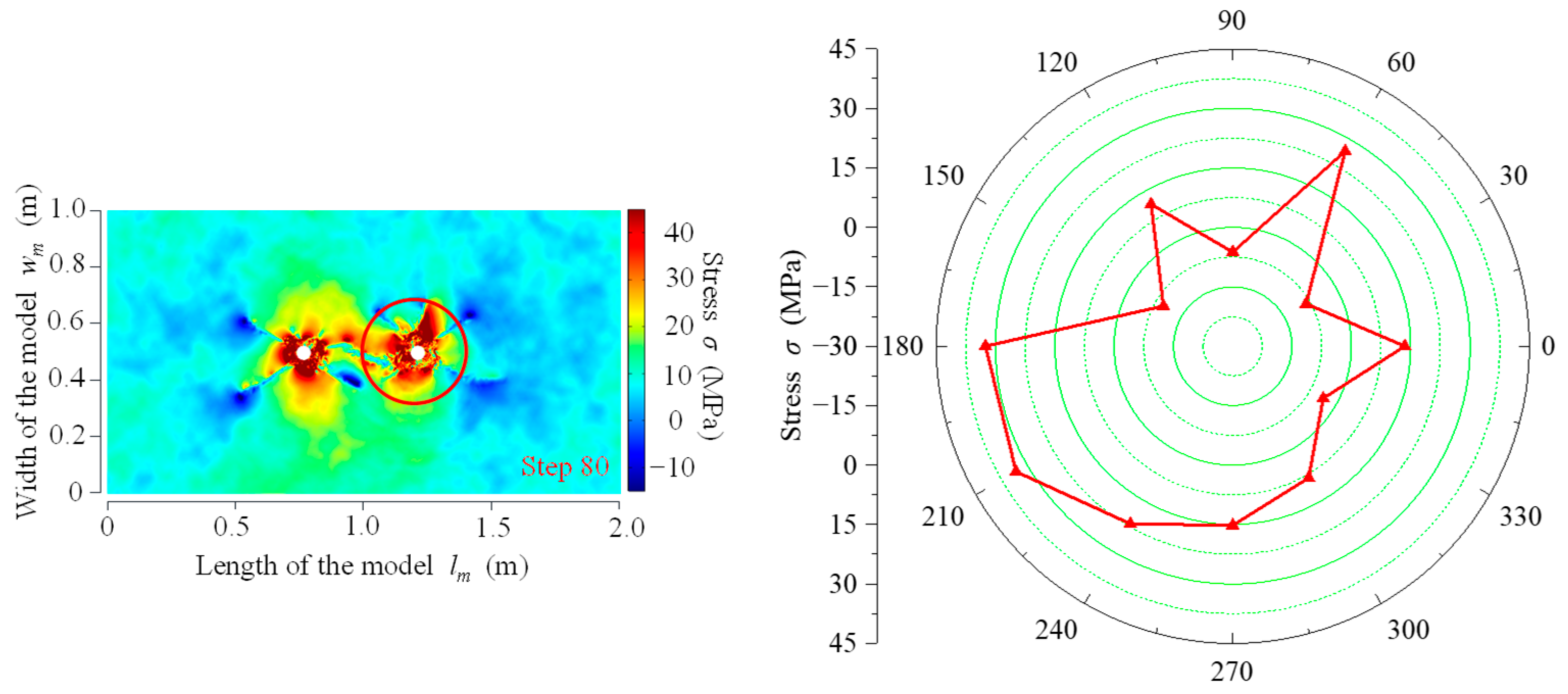
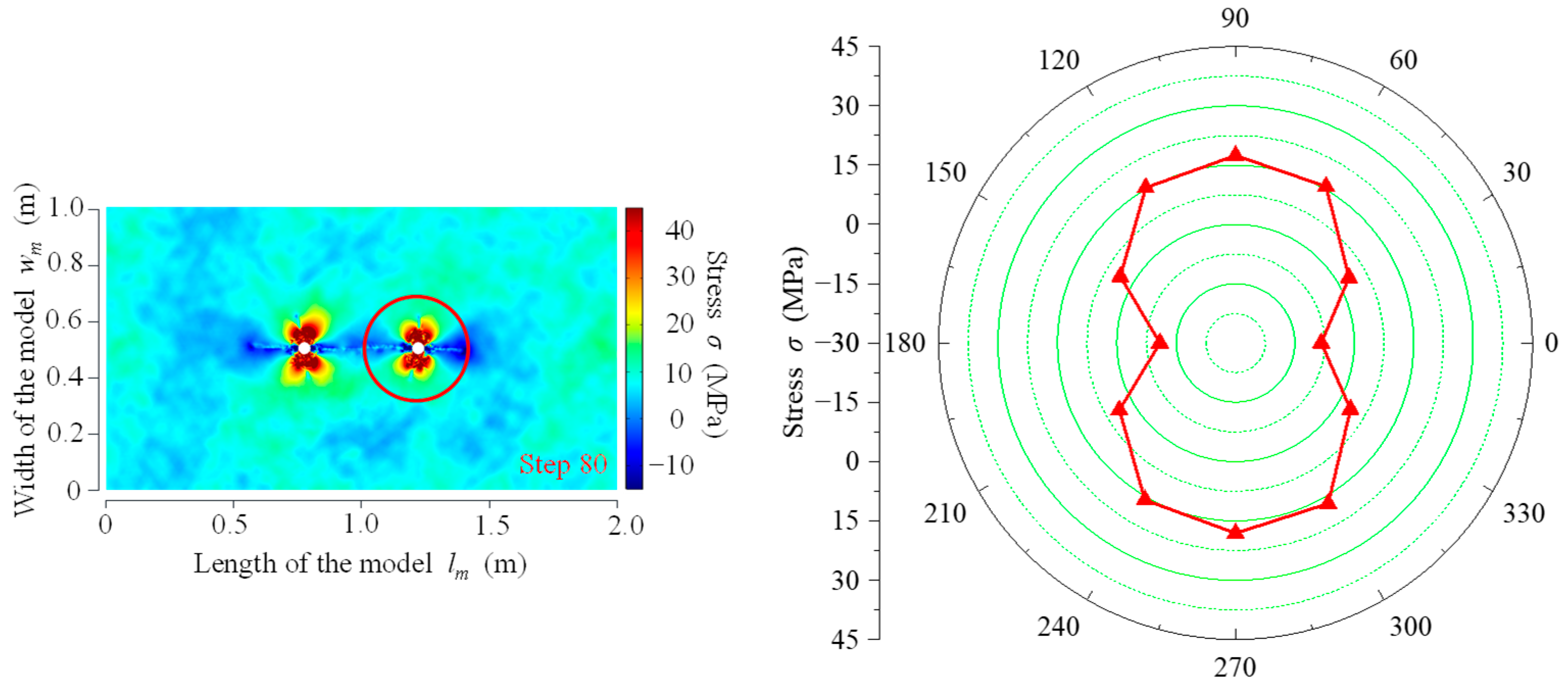
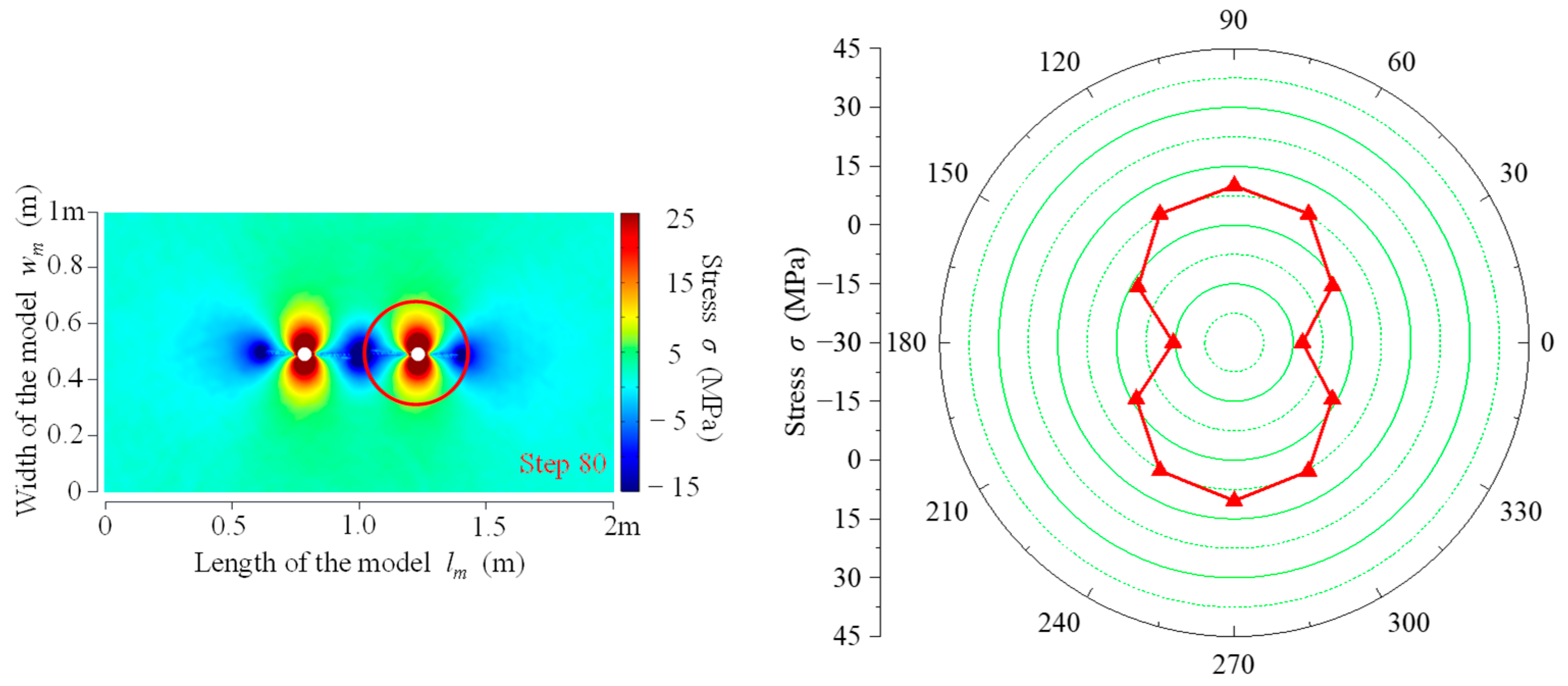
3.1.1. Stress Field Evolution Law for Double-Hole Fracture

The stress evolution processes during fracturing by CB, SCB, and IESF are illustrated in Figure 12, Figure 13 and Figure 14, respectively, with negative values denoting tensile stress and positive values indicating compressive stress. In CB, during the detonation wave phase (Steps 0–50), stress waves generated from both slotted boreholes interacted through superposition, initiating fractures under dynamic loading conditions. In the blast-induced gas phase (Steps 51–100), the blast-induced gas facilitated the crack propagation, with high compressive stress concentrated near the borehole wall that gradually diminished radially outward, and tensile stress concentration zones developed at the fracture tips. During the detonation wave phase (Steps 0–50) of SCB, both slotted boreholes exhibited directional fracture initiation along their predetermined splitting orientations. Tensile stress concentrations developed along the predetermined splitting orientations, while compressive stress dominated along the perpendicular orientations. The borehole wall experienced peak compressive stress magnitudes, which exhibited a gradient reduction from the wall outward into the surrounding rock mass. During the blast-induced gas phase, the fractures from both slotted boreholes propagated and ultimately coalesced. Prior to coalescence, the tensile stress concentrations at the fracture tips within the inter-borehole region interacted through superposition, intensifying stress concentration levels and creating larger tensile stress zones compared to those on the outer-borehole region. Following coalescence, the tensile stress concentrations diminished in both the inter-borehole region and the outer-borehole region. The stress evolution of IESF exhibited symmetric stress distribution aligned with the slotted orientation. During fracture initiation and extension, tensile stress superposition between boreholes progressively intensified, while compressive stress concentrations in non-slotted directions expanded radially. Following coalescence, stress concentration levels diminished significantly. This technique achieved directional rock fragmentation through tensile-dominated fracturing governed by high-pressure gas expansion, demonstrating superior directional fracture control capability compared to SCB.
At Step 80, a concentric circle with a 0.2 m radius was selected around the right slotted borehole. Stress values at 0°, 30°, 60°, 90°, 120°, 150°, 180°, 210°, 240°, 270°, 300°, and 330° positions along this circle were recorded for CB, SCB, and IESF, as shown in Figure 15, Figure 16 and Figure 17. In CB, the stress values at these 12 measurement points were recorded as follows: 13.45 MPa, −8.56 Mpa, 26.81 Mpa, −6.27 Mpa, 11.36 Mpa, −9.77 Mpa, 32.52 Mpa, 33.28 Mpa, 21.75 Mpa, 15.19 Mpa, 8.37 Mpa, and −3.62 Mpa. Among these, tensile stresses were observed at 30°, 90°, 150°, and 330°, while compressive stresses dominated the remaining eight angular positions. Therefore, CB exhibited a random stress distribution pattern. In SCB, tensile stress concentrations were observed along the energy-focused directions (0° and 180°). Specifically, tensile stresses of −10.89 Mpa and −8.33 Mpa were recorded at 180° and 0°, respectively. The tensile stress at 180° exceeded that at 0° by 2.56 Mpa, which displayed that the tensile stresses between the two holes were superimposed on each other, indicating enhanced stress-superimposed effects within the inter-borehole region compared to the outer-borehole region. In the non-shaped charge directions (30°, 60°, 90°, 120°, 150°, 210°, 240°, 270°, 300°, 330°), compressive stresses dominated. The directions perpendicular to the shaped charge orientation (90° and 270°) exhibited the highest compressive stresses, reaching 17.43 Mpa and 18.12 Mpa, respectively. During rock fragmentation using IESF, tensile stresses at the fracture tips along the slotted orientation (0° and 180°) were recorded as −12.62 Mpa and −14.47 Mpa, respectively. Similar to SCB, the inter-borehole region exhibited greater stress concentration intensity compared to the outer-borehole region. The stress values at the remaining 10 measurement points (30°, 60°, 90°, 120°, 150°, 210°, 240°, 270°, 300°, 330°) were recorded as −1.09 Mpa, 7.87 Mpa, 10.02 Mpa, 7.86 Mpa, −1.68 Mpa, −1.18 Mpa, 7.79 Mpa, 10.38 Mpa, 7.82 Mpa, and −1.17 Mpa, respectively. Among these, tensile stresses occurred at 30°, 150°, 210°, and 330°, while compressive stresses dominated the other six angular positions. This distribution confirmed that compression prevails in non-slotted directions. Given that rock’s compressive strength significantly exceeds its tensile strength, IESF achieved directional rock fragmentation with minimal energy input.
Both IESF and SCB showed significant stress superposition in the inter-hole region, but the difference is that SCB was first loaded around the borehole by the stress wave, followed by gas pressure from the blast-induced gas, while IESF was loaded by the high-pressure gas throughout. During the stress wave loading of the SCB, the rock mass over a larger area around the borehole was subjected to compressive stresses, and the same trend was maintained during the subsequent phases of blast-induced gas. Among the measurement points on the concentric circle with a 0.2 m radius of the borehole, the stresses values at the compressive stress points of SCB were larger than those at the same location in the IESF, and the compressive stress concentration area of SCB was significantly smaller than that of IESF. It indicated that some of the energy generated by the SCB propagated with the stress wave to the surrounding rock at a slight distance, resulting in a lower concentration of compressive stress around the borehole, and thus there was a subsequent decrease in the value of tensile stress generated in the energy-gathered direction. In IESF, since there is no energy dispersion by stress wave, the gas pressure was all concentrated on the surrounding rock near the borehole, thus generating stronger tensile stresses in the energy-gathered direction, and the superimposed effect of tensile stresses in the inter-hole region was more pronounced.

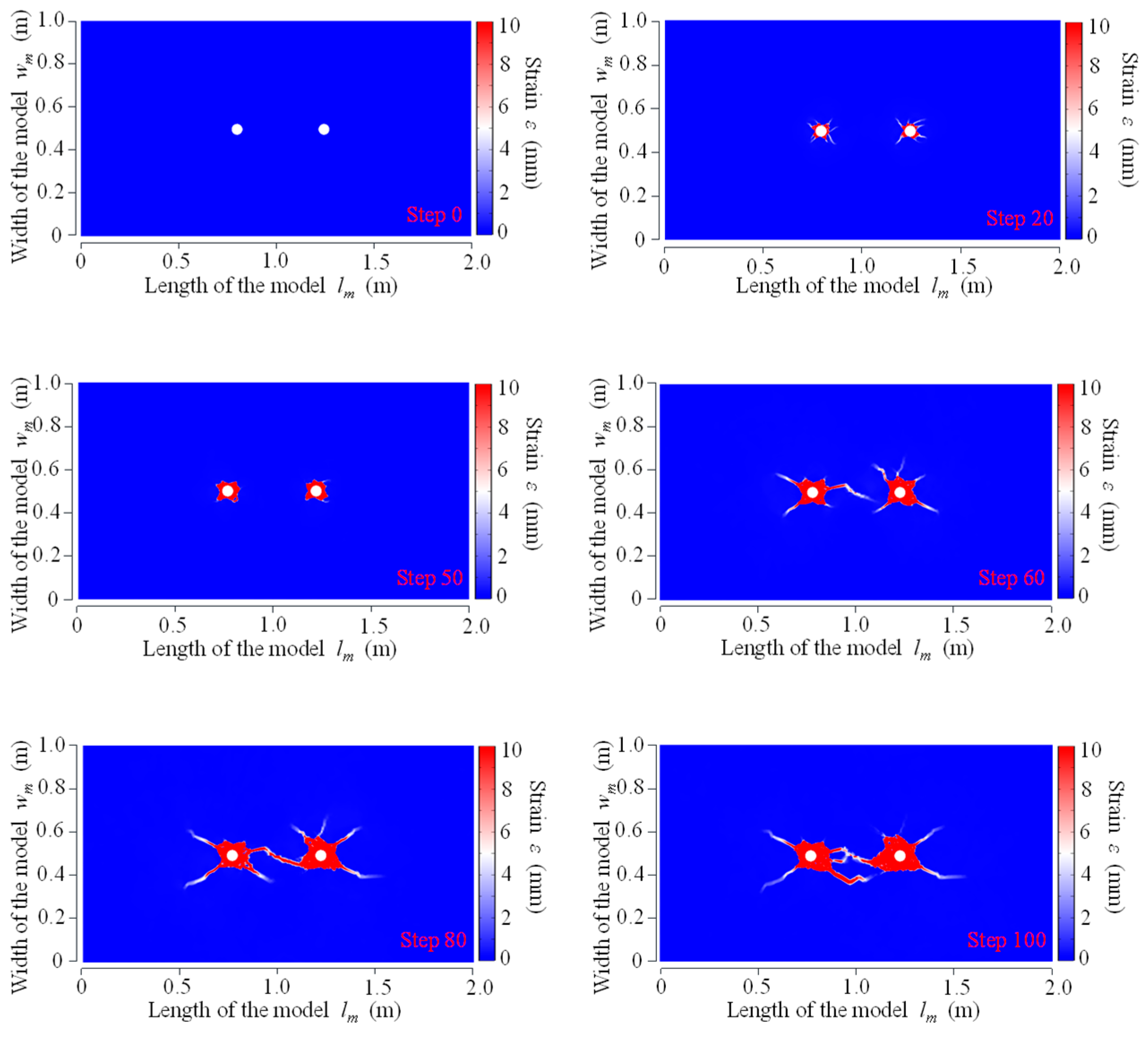
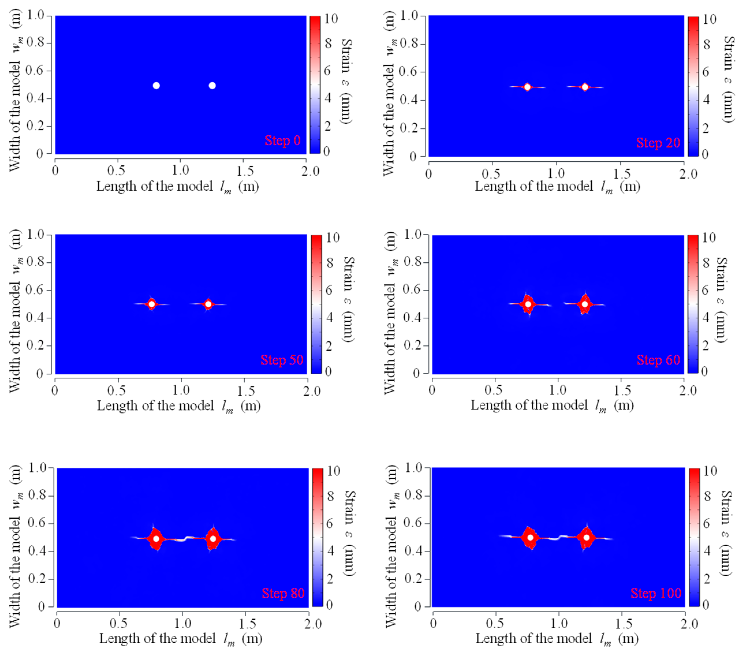
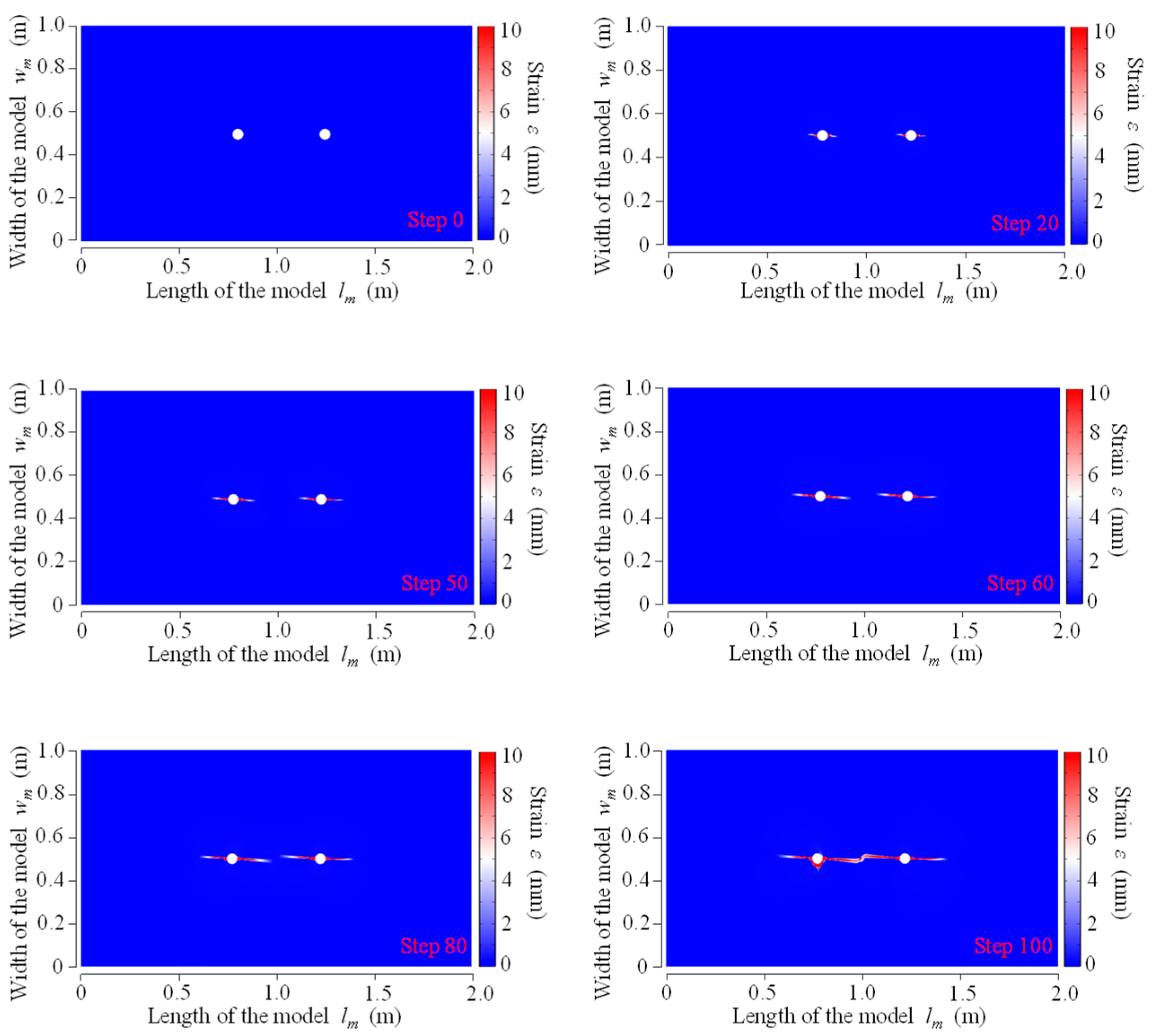
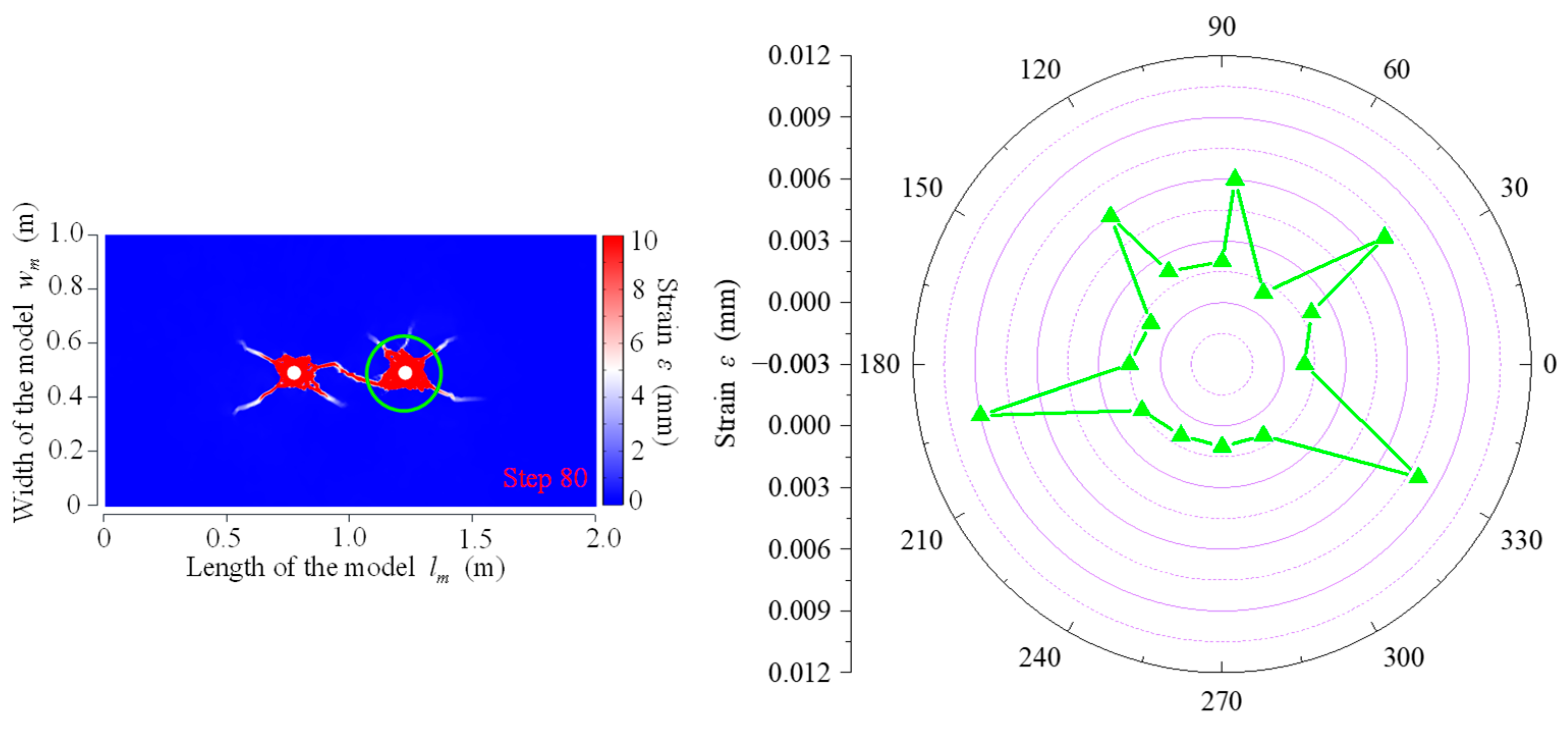
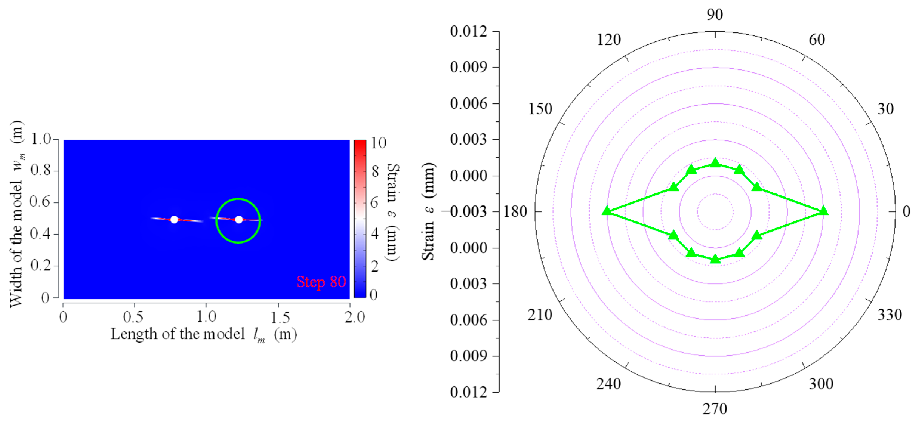
3.1.2. Strain Field Evolution Law for Double-Hole Fracture

The strain evolution processes during fracturing by CB, SCB, and IESF are respectively illustrated in Figure 18, Figure 19 and Figure 20. In CB, the first 50 steps (Steps 0–50) exhibited substantial strain in all directions around both boreholes due to omnidirectional stress wave extension, while during the subsequent 50 steps (Steps 50–100), high strain concentrations remained within a confined area near the boreholes, with only the four main fractures originating from the left borehole and the five main fractures from the right borehole showing significant strain beyond this zone, and strain in other regions diminishes considerably. In SCB, significant strain was observed in all directions within a limited radial range around both boreholes, while beyond this critical distance, elevated strain concentrations were localized exclusively along the slotted orientations, demonstrating superior directional rock-breaking efficacy compared to CB. Additionally, the strain reduction was observed at the fracture tips of the two directional fractures.
During rock fragmentation using IESF, elevated strain concentrations were localized exclusively along the slotted orientation of both boreholes, while minimal strain was observed in all other directions. It demonstrated the optimal directional fracture control capability of IESF.
At Step 80, a concentric circle with a radius of 0.135 m was selected around the right slotted borehole. Strain values at 0°, 30°, 60°, 90°, 120°, 150°, 180°, 210°, 240°, 270°, 300°, and 330° positions along this circle were recorded for CB, SCB, and IESF. For CB, strain values were additionally recorded at the intersections of this circle with the five primary fractures, located at angles of 38°, 86°, 127°, 192°, and 330° (these points were included in the aforementioned angular positions). The strain distributions at characteristic points along the circle for all three fracturing methods are illustrated in Figure 21, Figure 22 and Figure 23. In CB, significantly higher strain concentrations were observed at the intersections of the five primary fractures (38°, 86°, 127°, 192°, and 330°) with the concentric circle, recording strain magnitudes of 7 mm, 6 mm, 6 mm, 9 mm, and 8 mm, respectively. In contrast, the remaining points along the circle exhibited minimal strain values ranging from 1 mm to 2 mm. In SCB, significantly higher strain concentrations were localized along the energy-focused directions (0° and 180°) on the circle, with strain magnitudes of 7 mm and 8 mm, respectively. Perpendicular to the energy-focused directions (90° and 270°), strain values were reduced to 1.5 mm, while all other non-shaped charge directions exhibited strain below 1.5 mm, demonstrating that SCB effectively achieved directional rock fragmentation. During rock fragmentation using IESF, strain magnitudes of 6 mm were concentrated along the slotted orientations (0° and 180°), while non-slotted directions (30°, 60°, 90°, 120°, 150°, 210°, 240°, 270°, 300°, and 330°) exhibited uniformly low strains of 1 mm.
Both IESF and SCB produced much larger strain in the energy-focused directions than in the other direction, and both maintained lower strain levels in the non-energy-focused direction. However, the IESF did not show the phenomenon of strain prominence perpendicular to the energy-focused directions like SCB. The strains generated by IESF mainly increased rapidly in the energy-focused directions, and there were almost no high strain zones around the borehole. On the other hand, a region of high strain occurred over a larger area around the borehole during SCB. It indicated that IESF had a greater control ability over the energy distribution than CB as well as SCB.

3.2. In Situ Test Results of IESF

After the in situ roof-cutting test, the borehole inspection camera was used to observe the fractures generated in the borehole wall, and the results of its observations are shown in Figure 24. The same rock-breaking method of the two boreholes showed similar fracture development characteristics. Through the observation of fracture generation, it can be found that the fractures in CB boreholes were generated randomly, and cause greater damage to the rock mass. Due to the action of the slit-oriented tube, the SCB generated two symmetrical main fractures, and there were certain secondary fractures around the main fractures. In contrast, IESF generated only two directional fractures along the slotted orientation, symmetrically distributed on both axial sides of the borehole with an interfacial angle of approximately 180°.
Borehole inspection results demonstrated the following conclusion. After CB, the surrounding rock was subjected to stress much greater than the compressive strength of the rock, as it was initially subjected to detonation waves generated by the explosives. Consequently, crushed areas developed along the borehole wall, as illustrated in Figure 24a. Subsequently, blast-induced gases exerted pressure again on the borehole wall and penetrated existing fractures as “gas wedges”, promoting further crack propagation and ultimately generating multiple fractures. After blasting, the surrounding rock of the boreholes showed asymmetric fragmentation, with more severe fragmentation occurring on the inter-borehole rock mass side. This intensified fragmentation was the result of the superimposed effect of double-borehole loading. After SCB, the slit-oriented tube suppressed detonation waves in non-slotted directions, prioritizing energy release along the slotted orientation. This reduced shock impact on the rock mass around the borehole in non-slotted directions, ultimately forming a fracture along the slotted orientation, as illustrated in Figure 24b. However, the detonation wave infrequently generated compressive stress on the rock mass, leading to the formation of fine secondary fractures in non-slotted directions. Overall directional roof cutting was possible by SCB. Since IESF did not generate detonation waves during its reaction process, the tensile stress concentration generated under the action of the slit-oriented tube caused directional tensile failure in the rock mass along the slotted orientation, as illustrated in Figure 24c. The borehole walls exhibited no blasting-induced fragmentation or secondary fracture, demonstrating that the directional roof-cutting efficacy of IESF surpassed both CB and SCB.
In order to quantitatively characterize the effect of directional rock fragmentation, crack rate ϕ was introduced as a criterion [47].
ϕ = l 2 L
where l is the total length of the cracks generated. L is the length of charge section on both side of slotted orientation.
The slit rate can be used to analyze the ability to generate directional cracks. A higher crack rate indicated a greater ability to generate directional cracks in slotted orientation, while a lower crack rate indicated a weaker ability. The crack rates of SCB and IESF in the ten boreholes were counted separately and the results are shown in Table 1 and Table 2.
By calculating the crack rates separately, the average crack rate of SCB was found to be 85.0%, while that of IESF was 95.5%. The results showed that the average crack rates of IESF were 10.5% higher than those of SCB. Combined with the results of the borehole inspection, it can be found that the length of directional cracks generated by the SCB was lower than that of the IESF because part of the energy of the SCB was used to generate secondary cracks. IESF achieved a higher crack rate because it generated cracks only in the slotted orientation, and all the energy it released was used for crack initiation and propagation.

4. Discussion

4.1. Comparison of IESF with Other Rock-Breaking Methods

As a non-explosive directional rock-breaking method, IESF displays fundamental differences in rock-breaking mechanisms compared to CB and SCB, resulting in distinct fragmentation outcomes. In constructing the theoretical model, the effect of stress waves and blast-induced gas on the surrounding rock was taken into account in CB and SCB [45,46,47,48]. In the studies of Zhang et al. [48] and Yi et al. [49], the stress wave attenuation law and the stress field distribution around the borehole were established, respectively, and it was pointed out that the cracks would undergo expansion when the tangential tensile stress generated was greater than the tensile strength of the rock. The intensity factor of the crack tip of SCB under the action of the slit-oriented tube was given in the study of Gao et al. [50], and the crack extension conditions were given. The effect of the burst-induced gas in the SCB on the intensity factor of the crack tip was considered in the study of Wang et al. [51], and the corresponding propagation criterion was given. In this paper, when using IESF, the theoretical model was developed from the view that the generated high-pressure gases drove the fracture propagation. For the crack propagation criterion between the double holes, the gas pressure distribution within the crack was first determined, and this was used to derive the intensity factor at the crack tip. When it was greater than the dynamic fracture toughness of the rock, it is assumed that the crack produced an extension.
In numerical simulations, the rock-breaking process demonstrated randomness in energy distribution and a highly destructive nature characterized by extensive disturbance to surrounding rock in CB. Numerical simulation results revealed randomness in crack quantity and orientation, along with a wide distribution of stress fields. Similar results have been found in others’ simulations, where the use of CB in both tunnels and coal mines produced extensive damage areas around the boreholes [52,53], demonstrating the characteristics of CB’s extensive and strong disturbances. In SCB, although the slit-oriented tube can effectively protect the non-slit directions and control the energy transmission path of blast-induced gases, it only partially suppresses the propagation of stress waves. Consequently, numerical simulations revealed compressive stress fields and strain fields over a relatively large area around the borehole. This shows consistency with the results of SCBs in the studies of others, which produce some degree of damage in the non-slotted direction, both in laboratory tests and numerical simulations [54,55]. In contrast, as a non-explosive rock-breaking method, IESF showed a completely different rock-breaking process. Unlike CB and SCB, IESF only utilizes high-pressure gas to apply loads to the surrounding rock. Therefore, there is no stress wave generated during the breaking process, and the crack propagation mainly relies on the tensile stress concentration generated by the high-pressure gas, so the influence on the surrounding rock of the borehole is much smaller than that of CB and SCB. There was only localized compressive stress concentration zones near the borehole without extensive displacement fields.
The results of in situ tests present similar characteristics. The in situ tests exhibited the formation of multiple crushed areas and numerous cracks in CB, and in situ tests also demonstrated the generation of a certain number of secondary cracks within boreholes in SCB, with an average crack rate of 85% in SCB. The results of IESF generated only two directional cracks in the slotted direction, and the crack rate was kept above 95%. A similar phenomenon can be observed in the in situ tests of others [53,54]. There was a random distribution of cracks generated by crushed areas in CB boreholes in the study by Huang et al. [56]. The presence of two main cracks in the borehole of SCB can be seen in the study of Qiao et al. [57]. The results of in situ tests showed that IESF, as a non-explosive rock-breaking method, can effectively replace explosives to realize directional damage to rock, and even better than SCB in directional fracturing.

4.2. Interrelationship of Double-Borehole Superimposed Effects Between Different Slotted Methods

Because of the rock opacity, it is difficult to directly observe the rock damage process between the double holes in the in situ test; the process of crack development between the double holes can be visualized by numerical simulation. Under double-borehole loading conditions, the three rock-breaking methods, CB, SCB, and IESF, all induce superimposed stress effects in the inter-borehole rock mass. According to the results of numerical simulation, these methods also exhibit greater strain and more extensive rock damage in the inter-borehole region compared to rock masses in other orientations. In CB, the superposition area between the double holes is large due to the transmission of stress waves, so the measurement points between the double holes in the numerical simulation results all exhibited high values of compressive stress. The effect of inter-hole distance on the superposition of stresses was analyzed in detail by numerical simulation in the study by Pu et al. [58], and their results showed that when the borehole spacing was 9 cm or 11 cm, the main cracks between the boreholes failed to intersect, exhibiting a vertically offset configuration. In SCB, the stress field between the double holes exhibited tensile stresses due to the slit-oriented tube, and the value of tensile stresses superimposed between the double holes was greater than that on the other side, as shown by the numerical simulation results. In SCB, the concentration of tensile stress in the energy-gathering direction, tensile stress was −10.89 MPa in the inter-borehole region and −8.33 MPa on the outer-borehole region. As it was shown in the double-borehole SCB simulation results by Yin et al. [59], in the concentric circle monitoring points centered on the borehole, the stress generated in the direction of the axis line of the double borehole was more than 45 MPa, which was much larger than the maximum value of 16.6 MPa in the direction perpendicular to the axis line. As the monitoring points moved away from the borehole, the stress directed toward the perpendicular axis line decreased significantly, but the inter-hole region was still subjected to tensile stress, proving the superposition of the stress field between the holes. The effect of hole spacing on the superposition effect was carried out in Guo’s study [60], and the simulation results showed that the superposed stress field at a spacing of 500 mm was sufficient to produce directional cracks in the rock, but when the hole spacing was increased to 600 mm, the superposed stress could not satisfy the conditions for rock damage due to the attenuation of the stress.
In the simulation results of IESF, a stronger tensile stress field superposition effect was shown in the inter-hole region. The main reason is that the gas pressure in the fracturing process of IESF was concentrated in the surrounding rock near the boreholes, so the tensile stress formed in the slotted direction was stronger, and it showed higher superposed stress values. During fracturing by IESF, the concentration of tensile stress in the energy-gathering direction, the tensile stress in the inter-borehole region was −14.47 MPa, greater than the tensile stress of −12.62 MPa in the outer-borehole region. This characteristic is also due to the fact that IESF relies only on gas pressure and not on stress waves during the rock-breaking process, so it does not generate a wider range of compressive stress field as SCB does. This indicated that IESF showed stronger energy utilization in the process of directional fracturing and can realize a better directional fracturing effect.

5. Conclusions

This study of the double-borehole superimposed effect of coal-based solid waste expansive agent for directional rock fragmentation resulted in the following main conclusions.
(1)
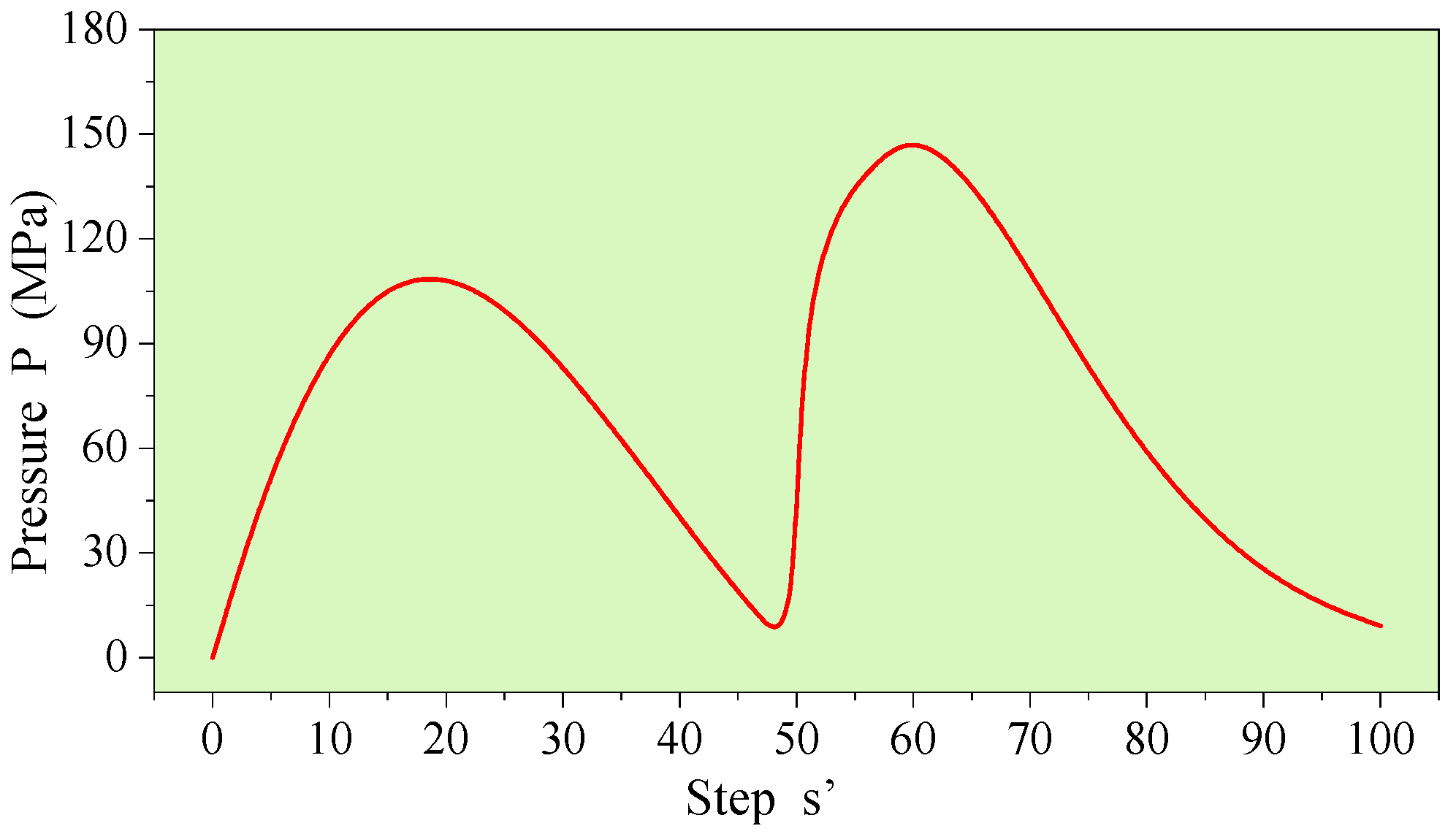
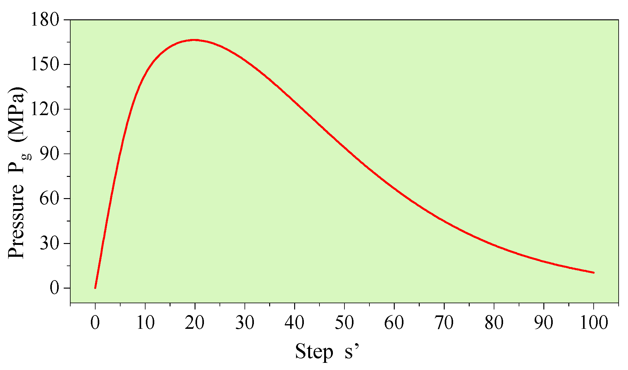
The instantaneous expansion with a single fracture (IESF) generates approximately 300 mL of high-temperature and high-pressure gases from 1 g of solid material within 0.05–0.5 s. Through the directional action of slit-oriented tubes, these high-pressure gases transform traditional three-dimensional volumetric fracturing into two-dimensional planar fractures. The gas pressure distribution law of IESF in directional cracks was analyzed and the directional fracture expansion criterion was established.
(2)
The stress fields of CB, SCB, and IESF were analyzed by numerical simulations. The stress distribution in CB was relatively random, and a wide range of compressive stress field was formed around the borehole. In SCB, the concentration of tensile stress in the energy-gathering direction, tensile stress was −10.89 MPa in the inter-borehole region and −8.33 MPa on the outer-borehole region. The tensile stress in the inter-borehole region was 2.56 MPa greater than the tensile stress in the outer-borehole region. During fracturing by IESF, the concentration of tensile stress in the energy-gathering direction, the tensile stress in the inter-borehole region was −14.47 MPa, greater than the tensile stress of −12.62 MPa in the outer-borehole region. Similar to SCB, there was a stress-superimposed effect between the double holes of IESF, while IESF achieved a better directional effect with less energy.
(3)
The strain fields of CB, SCB and IESF were analyzed by numerical simulations. In CB, the strain was concentrated at the main fractures. SCB exhibited higher strain along the energy-gathering direction, with strain values of 7 mm and 8 mm on each side, while the strain perpendicular to the shaped charge direction measured 1.5 mm. IESF exhibited a strain of 6 mm along the slotted orientation, while strains in non-slotted directions measured less than 1 mm. The strains generated by IESF mainly increased rapidly in the energy-focused directions, and there were almost no high-strain zones around the borehole. It indicated that IESF had a greater control ability over the energy distribution than CB as well as SCB.
(4)
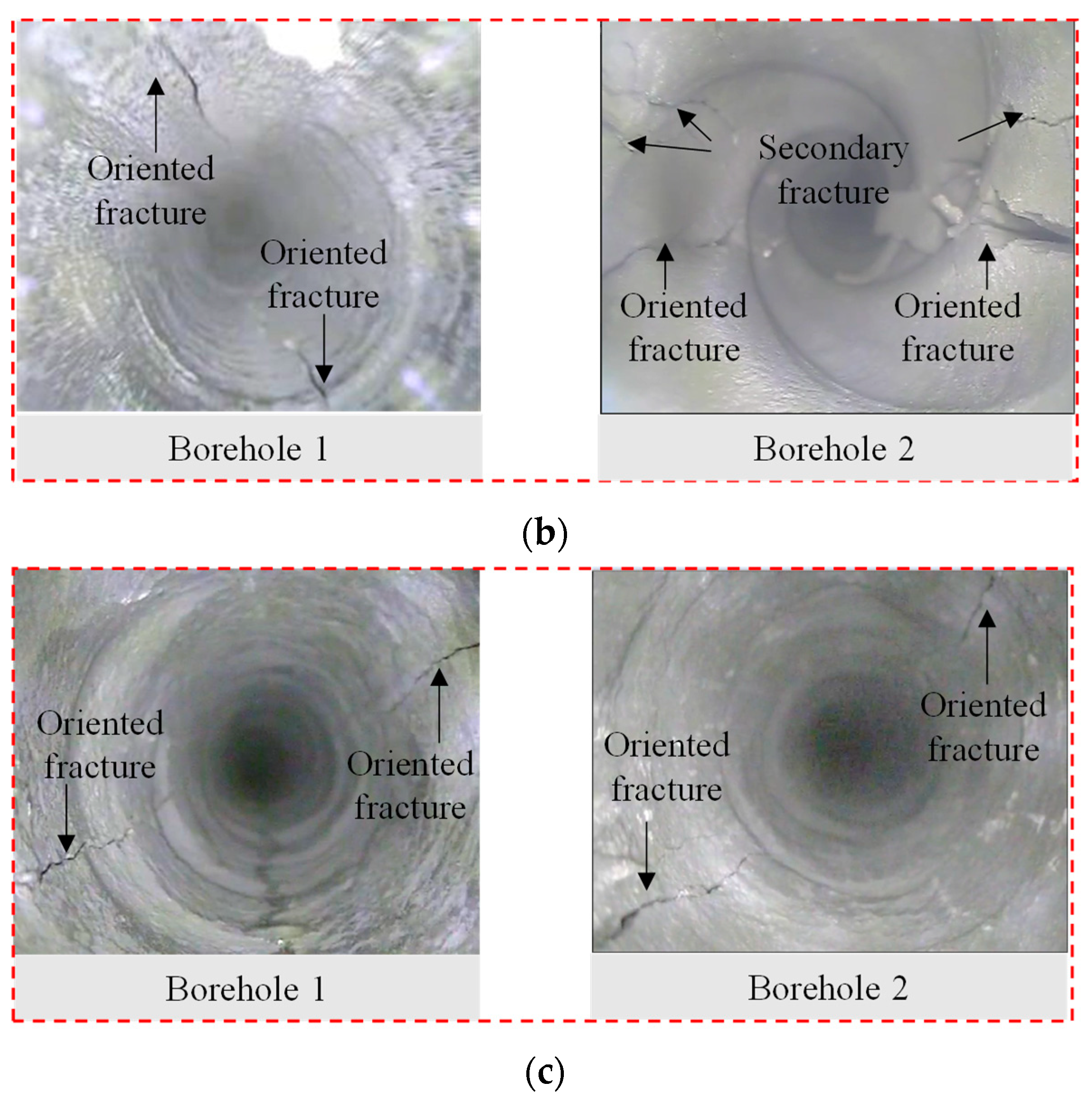
In situ tests showed that there was a superimposed effect under double-hole loading, and the pattern was consistent with the numerical simulation results. The fracture distribution in CB was relatively random. In SCB, the main fracture was generated along the slotted orientation, while there were small secondary fractures occasionally generated in the other direction, and the damage in the inter-borehole region was greater than that in the outer-borehole region. The average crack rate of SCB was found to be 85.0%, while that of IESF was 95.5%. IESF achieved superior directional fracture control compared to both CB and SCB, generating only two directional fractures along the slotted orientation, and produced longer axial cracks.

Author Contributions

Conceptualization, Q.Z. and M.H.; methodology, Q.Z.; software, S.G.; validation, C.W., Y.W. and S.G.; formal analysis, C.Y.; investigation, Y.W.; resources, R.Y.; data curation, K.C.; writing—original draft preparation, K.C.; writing—review and editing, Q.Z. and C.Y.; visualization, K.C.; supervision, J.W.; project administration, R.Y; funding acquisition, Q.Z. and M.H. All authors have read and agreed to the published version of the manuscript.

Funding

This work is supported by the National Key Laboratory Fund Project of China Nuclear Uranium Industry (NKLUR-2024-YB-016), the National Natural Science Foundation of China (No. 52404155), Basic Research Program of Jiangsu (No. BK20231071), the China Postdoctoral Science Foundation (No. 2024M753523), the Jiangsu Provincial Association for Science and Technology Youth Science and Technology Talent Support Project (No. JSTJ-2023-XH036) and the Fundamental Research Funds for the Central Universities (No. 2023QN1001), which are gratefully acknowledged. This paper is supported by the opening project of State Key Laboratory of Explosion Science and Safety Protection (Beijing Institute of Technology). The opening project number is KFJJ24-20M.

Institutional Review Board Statement

Not applicable.

Informed Consent Statement

Not applicable.

Data Availability Statement

The original contributions presented in this study are included in the article. Further inquiries can be directed to the corresponding author.

Conflicts of Interest

Author Chun Yang was employed by the Guangxi China Tin Group Stock Co., Ltd. The remaining author declare that the research was conducted in the absence of any commercial or financial relationships that could be construed as a potential conflict of interest.

Abbreviations

The following abbreviations are used in this manuscript:
IESFInstantaneous Expansion with a Single Fracture
CBConventional Blasting
SCBShaped Charge Blasting

References

  1. Zhang, X.F.; Mu, Z.L.; Jiang, C.L.; Wang, H.; Chen, Y.; Zhuang, J.X.; Man, C.; Cao, J.L.; Liu, C.; Yang, J.; et al. Numerical and experimental study on pressure relief mechanism of roof blasting along gob-side roadway. Appl. Sci. 2025, 15, 3168. [Google Scholar] [CrossRef]
  2. Lu, Y.; He, B.G.; Li, H.P.; Li, Q.; Ren, C. Theoretical and numerical investigation of damage zones in deep tunnels within a layered rock mass under full-face blasting. Int. J. Rock Mech. Min. Sci. 2025, 188, 106053. [Google Scholar] [CrossRef]
  3. Zhang, Q.; He, M.C.; Guo, S.; Yang, R.Z.; Chen, K.; Wang, C. Study on the mechanism and preliminary application of efficient directional rock breaking using a coal-based solid waste non-explosive expansive agent. Chin. J. Rock Mech. Eng. 2025, 44, 898–911. [Google Scholar] [CrossRef]
  4. He, M.C.; Wang, Q.; Wu, Q.Y. Innovation and future of mining rock mechanics. J. Rock Mech. Geotech. Eng. 2021, 13, 1–21. [Google Scholar] [CrossRef]
  5. Zhang, Q.; He, M.C.; Wang, J.; Guo, S.; Wang, C.; Hong, C.J.; Chen, K.; Yang, R.Z.; Zhang, X.P.; Yang, J.W. Non-explosive directional fracturing blasting using coal-based solid waste expanding agent. J. Rock Mech. Geotech. Eng. 2025, 17, 3691–3710. [Google Scholar] [CrossRef]
  6. Zhang, X.Y.; Hu, J.Z.; Xue, H.J.; Mao, W.B.; Gao, Y.B.; Yang, J.; He, M.C. Innovative approach based on roof cutting by energy-gathering blasting for protecting roadways in coal mines. Tunn. Undergr. Space Technol. 2020, 99, 103387. [Google Scholar] [CrossRef]
  7. Zhang, Q.; He, M.C.; Wang, J.; Guo, S.; Zhu, C.; Tao, Z.G.; Wang, C. Investigation of a non-explosive directional roof cutting technology for self-formed roadway. Int. J. Min. Sci. Technol. 2022, 32, 997–1008. [Google Scholar] [CrossRef]
  8. He, C.L.; Yang, J. Experimental and numerical investigations of dynamic failure process in rock under blast loading. Tunn. Undergr. Space Technol. 2019, 83, 552–564. [Google Scholar] [CrossRef]
  9. Li, Q.; Li, H.B.; Fu, S.Y.; Ju, M.H.; Li, X.F. Study on the most optimistic hole spacing for double-hole blasting under high in-situ stresses. Chin. J. Rock Mech. Eng. 2025, 44, 678–690. [Google Scholar] [CrossRef]
  10. Yang, J.H.; Sun, W.B.; Yao, C.; Zhang, X.B. Mechanism of rock fragmentation by multi-hole blasting in highly-stressed rock masses. Explos. Shock Waves 2020, 40, 075202. [Google Scholar] [CrossRef]
  11. Zhao, J.J.; Zhang, Y.; Ranjith, P.G. Numerical simulation of blasting-induced fracture expansion in coal masses. Int. J. Rock Mech. Min. Sci. 2017, 100, 28–39. [Google Scholar] [CrossRef]
  12. Yuan, W.; Liu, S.G.; Wang, W.; Su, X.B.; Li, Z.H.; Li, J.X.; Wen, L.; Chang, J.F.; Sun, X.Y. Numerical study on the fracturing mechanism of shock wave interactions between two adjacent blast holes in deep rock blasting. Earthq. Eng. Eng. Vib. 2019, 18, 735–746. [Google Scholar] [CrossRef]
  13. Zhou, Z.; Ma, J.; Wang, J.; Guan, S.; Zhang, X.; Yang, Y. Evolution Characteristics of Strain and Displacement Fields in Double-Hole Short-Delay Blasting Based on DIC. Processes 2024, 12, 1291. [Google Scholar] [CrossRef]
  14. Wei, C.H.; Zhu, W.C.; Bai, Y.; Li, S. Numerical simulation on two-hole blasting of rock under different joint angles and in-situ stress conditions. Chin. J. Theor. Appl. Mech. 2016, 48, 926–935. [Google Scholar] [CrossRef]
  15. Cao, R.Y.; Li, Y.P.; Feng, C.; Zhang, Y.M. Study on the guiding mechanism of multiple and empty holes under explosion load. Min. Metal. Explor. 2024, 41, 277–286. [Google Scholar] [CrossRef]
  16. Guo, D.Y.; Zhao, J.C.; Zhang, C.; Zhu, T.G. Mechanism of control hole on coal crack initiation and propagation under deep-hole cumulative blasting in coal seam. Chin. J. Rock Mech. Eng. 2018, 37, 919–930. [Google Scholar] [CrossRef]
  17. Song, Y.Q.; Li, X.S.; Guo, D.Y. Numerical simulation of multi-hole and same delay time of cumulative blasting in coal seam and its application. J. Chin. Coal Soc. 2018, 43, 469–474. [Google Scholar] [CrossRef]
  18. Li, X.S. Splitting Mechanism and Influencing Factors of the Cumulative Blasting. Doctor’s Thesis, China University of Mining & Technology-Beijing, Beijing, China, 2021. [Google Scholar]
  19. Wu, B.; Xu, S.X.; Meng, G.W.; Cui, Y.Z.; Cai, J.H.; Zhang, Y. Study on the dynamic evolution of through-crack in the double hole of elliptical bipolar linear-shaped charge blasting. Shoc. Vib. 2021, 2021, 3792765. [Google Scholar] [CrossRef]
  20. Yue, Z.W.; Tian, S.Y.; Chen, Z.Y. Influence of the interval between holes on crack propagation in slit charge blasting. Chin. J. Rock Mech. Eng. 2018, 37, 2460–2467. [Google Scholar] [CrossRef]
  21. He, M.C.; Gao, Y.B.; Yang, J.; Guo, Z.B.; Wang, E.Y.; Wang, Y.J. An energy-gathered roof cutting technique in no-pillar mining and its impact on stress variation in surrounding rocks. Chin. J. Rock Mech. Eng. 2017, 36, 1314–1325. [Google Scholar] [CrossRef]
  22. Yang, L.Y.; Wang, Q.C.; Xu, L.N.; Yang, R.S.; Cao, Y.J. Fracture path of cracks emigrating from two circular holes under blasting load. Theor. Appl. Fract. Mech. 2020, 108, 102559. [Google Scholar] [CrossRef]
  23. Shnorhokian, S.; Mitri, H. Evaluating the application of rock breakage without explosives in underground construction—A critical review of chemical demolition agents. Minerals 2022, 12, 220. [Google Scholar] [CrossRef]
  24. Zhang, Q.; He, M.C.; Guo, S.; Qi, J.C.; Yang, J.; Wang, C.; Xia, M.; Li, L.N. Investigation on the key techniques and application of the new-generation automatically formed roadway without coal pillars by roof cutting. Int. J. Rock Mech. Min. Sci. 2022, 152, 105058. [Google Scholar] [CrossRef]
  25. Li, J.T. Propagation Rules of Hydraulic Fracturing Under Multi-Boreholes Synchronous Linkage Control for Coal Seam and Its Application. Doctor’s Thesis, Northeastern University, Shenyang, China, 2021. [Google Scholar]
  26. Huang, L.K.; Tan, J.; Fu, H.F.; Liu, J.J.; Chen, X.Y.; Liao, X.C.; Wang, X.H.; Wang, C. The non-plane initiation and propagation mechanism of multiple hydraulic fractures in tight reservoirs considering stress shadow effects. Eng. Fract. Mech. 2023, 292, 109570. [Google Scholar] [CrossRef]
  27. Yang, W.D.; Lv, X.X.; Wang, L.G.; Peng, D.; Chen, X.Z. A DEM–CFD coupling method for modelling two-hole synchronous hydraulic fracturing. Geomech. Geophys. Geo-Energ. Geo-Resour. 2023, 9, 6. [Google Scholar] [CrossRef]
  28. Jiang, Y.L.; Liang, W.G.; Lian, H.J.; He, W. Experimental study of hydraulic fracture propagation in multi-hole synchronous fracturing in horizontal wells in sandstone. Int. J. Rock Mech. Min. Sci. 2025, 186, 106013. [Google Scholar] [CrossRef]
  29. Wang, L.C.; Duan, K.; Zhang, Q.Y.; Zhang, X.F.; Liu, C.C. Visualization of the dynamic propagation of two simultaneously-stimulated hydraulic fractures: Competition and interaction. Int. J. Rock Mech. Min. Sci. 2025, 186, 106036. [Google Scholar] [CrossRef]
  30. Zhao, X.L.; Huang, B.X.; Wang, Z. Experimental investigation on the basic law of directional hydraulic fracturing controlled by dense linear multi-hole drilling. Rock Mech. Rock Eng. 2018, 51, 1739–1754. [Google Scholar] [CrossRef]
  31. Li, L.W.; Wu, W.B. Directional hydraulic fracturing technology for prefabricated longitudinal guide seams in a coal mine tight sandstone roof. Energy Explor. Exploit. 2022, 40, 400–420. [Google Scholar] [CrossRef]
  32. Hu, S.C.; Han, J.M.; Cheng, Y.F.; Qi, J.L.; Huang, J.H.; Gao, Z.H.; Guo, S.H.; Yang, L. Analysis of mechanical mechanism and influencing factors of directional fracturing of multi-hole sleeve. J. Chin. Coal Soc. 2024, 49, 3366–3380. [Google Scholar] [CrossRef]
  33. Jaber, T.S.; Amir, G.; Seyedahmad, H.; Abdolnabi, H. Debonding and coalescence in the interaction between hydraulic and natural fracture: Accounting for the effect of leak-off. J. Nat. Gas Sci. Eng. 2016, 36, 454–462. [Google Scholar] [CrossRef]
  34. Sampath, K.H.S.M.; Perera, M.S.A.; Elsworth, D.; Ranjith, P.G.; Matthai, S.K.; Rathnaweera, T.; Zhang, G. Effect of coal maturity on CO2-based hydraulic fracturing process in coal seam gas reservoirs. Fuel 2019, 236, 179–189. [Google Scholar] [CrossRef]
  35. Zhang, H.; Liu, B.B.; He, Q.Y. Visualized hydraulic fracture re-orientation in directional hydraulic fracturing by laboratory experiments in gelatin samples. Appl. Sci. 2024, 14, 2047. [Google Scholar] [CrossRef]
  36. Huang, B.X.; Liu, J.W.; Zhang, Q. The reasonable breaking location of overhanging hard roof for directional hydraulic fracturing to control strong strata behaviors of gob-side entry. Int. J. Rock Mech. Min. Sci. 2018, 103, 1–11. [Google Scholar] [CrossRef]
  37. Valderrama, J.O. The state of the cubic equations of state. Ind. Eng. Chem. Res. 2003, 42, 1603–1618. [Google Scholar] [CrossRef]
  38. Nilson, R.H.; Proffer, W.J.; Duff, R.E. Modelling of gas-driven fractures induced by propellant combustion within a borehole. Int. J. Rock Mech. Min. Sci. Geomech. Abs. 1985, 22, 3–19. [Google Scholar] [CrossRef]
  39. Man, K.; Liu, X.L.; Song, Z.F.; Song, X.R.; Cheng, H.L.; Guo, Z.F.; Liu, Z.X.; Yu, Y.P. Research on fracture surface morphology of rock with static and dynamic fracture toughness. J Cent. South Univ. (Sci. Technol.) 2021, 52, 2876–2886. [Google Scholar] [CrossRef]
  40. Xie, Q.; Li, S.X.; Liu, X.L.; Gong, F.Q.; Li, X.B. Effect of loading rate on fracture behaviors of shale under mode I loading. J. Cent. South Univ. 2020, 27, 3118−3132. [Google Scholar] [CrossRef]
  41. Weibull, W. A statistical distribution function of wide applicability. J. Appl. Mech. 1951, 18, 293–297. [Google Scholar] [CrossRef]
  42. Zhu, W.C.; Yan, B.X.; Liu, X.G.; Yang, Z.; Guan, K. Rock creep deformation triggered by dynamic disturbance: Numerical simulation. Int. J. Geomech. 2022, 22, 04022101. [Google Scholar] [CrossRef]
  43. Chen, S.K.; Wei, C.H.; Yang, T.H.; Zhu, W.C.; Liu, H.L.; Ranjith, P.G. Three-dimensional numerical investigation of coupled flow-stress-damage failure process in heterogeneous poroelastic rocks. Energy 2018, 11, 1923. [Google Scholar] [CrossRef]
  44. Zhu, W.C.; Wei, C.H.; Li, S.; Wei, J.; Zhang, M.S. Numerical modeling on destress blasting in coal seam for enhancing gas drainage. Int. J. Rock Mech. Min. Sci. 2013, 59, 179–190. [Google Scholar] [CrossRef]
  45. Gao, Y.B. Study on Key Issues of 110 Mining Method Used in a Thick Coal Seam—A Case Study in Ningtiaota Coal Mine. Doctor’s Thesis, China University of Mining & Technology-Beijing, Beijing, China, 2018. [Google Scholar]
  46. Zhang, Q.; Tao, Z.G.; Yang, C.; Guo, S.; He, M.C.; Zhang, C.Y.; Niu, H.Y.; Wang, C.; Wang, S. Experimental and numerical investigation into the non-explosive excavation of tunnels. J. Rock Mech. Geotech. Eng. 2022, 14, 1885–1900. [Google Scholar] [CrossRef]
  47. Zhang, Q.; He, M.C.; Wang, J.; Guo, S.; Guo, Z.B.; Liu, X.Y.; Hu, J.Z.; Ma, Z.M.; Fan, L.X.; Guo, P.F. Instantaneous expansion with a single fracture: A new directional rock-breaking technology for roof cutting. Int. J. Rock Mech. Min. Sci. 2020, 132, 104399. [Google Scholar] [CrossRef]
  48. Zhang, X.; Liu, Z.G.; Chang, X.; Xue, Y.L.; Zhang, J.Y. Study on damage characteristics and fracture mechanisms of coal under high stress environment during blasting. Eng. Fract. Mech. 2025, 314, 110772. [Google Scholar] [CrossRef]
  49. Yi, C.P.; Johansson, D.; Nyberg, U.; Beyglou, A. Stress wave interaction between two adjacent blast holes. Rock Mech. Rock Eng. 2016, 49, 1803–1812. [Google Scholar] [CrossRef]
  50. Gao, Y.B.; Yang, J.; Zhang, X.Y.; Xue, H.J.; He, M.C. Study on surrounding rock control of roadways in deep coal mines based on roof cutting and pressure release technology by directional tensile blasting. Chin. J. Rock Mech. Eng. 2019, 38, 2045–2056. [Google Scholar] [CrossRef]
  51. Wang, K.F.; Zhang, C.S.; Hao, B.Y.; Zhang, S.L. Study on initiation and propagation mechanism of internal cracks caused by dynamic and static action of shaped charge blasting under in-situ stress. Coal Sci. Technol. 2023, 51, 50–64. [Google Scholar] [CrossRef]
  52. Cao, A.Y.; Hao, Q.; Cui, Y.J.; Huang, S.X.; Peng, Y.J.; Gao, Z.; Gao, H.B.; Li, D.; Gao, F. Crack extension mechanism of deep-hole blasting in the roof of high-tectonic-stress region and its application. J. Min. Saf. Eng. 2025, 42, 97–107. [Google Scholar] [CrossRef]
  53. Ji, L.; Yao, Y.K.; Zhou, C.B.; Zhang, Z.; Cao, H.Q.; Wu, T.Y. Research on cumulative damage effects and safety criterion of surrounding rock in bench blasting of a large cross-section tunnel. Alex. Eng. J. 2024, 108, 626–639. [Google Scholar] [CrossRef]
  54. Guo, Y.C.; Yang, R.S.; Peng, S.P.; Xiao, C.L. Experimental study on decoupled charge blasting-induced crack propagation with parabolic shaped charge. Eng. Frac. Mech. 2024, 304, 110178. [Google Scholar] [CrossRef]
  55. Xu, S.X.; Wu, B.; Zhang, H.L.; Qi, S.X.; Bian, H.B.; Wang, J.J. Directional crack propagation and optimization strategies for multi-hole shaped charge blasting in tunnel construction. Structures 2025, 72, 108268. [Google Scholar] [CrossRef]
  56. Huang, W.; Jing, G.; Ma, L.Q.; Zhao, L.L.; Wang, S. Research on blasting technology for thick and hard roof fracturing in isolated island coal mine working face. Sci. Rep. 2025, 15, 14534. [Google Scholar] [CrossRef] [PubMed]
  57. Qiao, G.D.; Liu, Z.G.; Gao, K.; Zhang, S.C.; Zhang, J.Y.; Fu, S.G. Experimental study on optimum blasting method of crossing hard rock normal fault in fully mechanized mining face. J. Min. Saf. Eng. 2023, 40, 507–516. [Google Scholar] [CrossRef]
  58. Pu, C.J.; Yang, X.; Xiao, D.J.; Cheng, J.L.; Zhou, L.; Chen, X. Numerical simulation of double-hole crack propagation under explosion load. J. Vib. Shock 2022, 41, 300–311. [Google Scholar] [CrossRef]
  59. Yin, Y.; Sun, Q.; Zou, B.P.; Ma, Q.Y. Numerical study on an innovative shaped charge approach of rock blasting and the timing sequence effect in microsecond magnitude. Rock Mech. Rock Eng. 2021, 54, 4523–4542. [Google Scholar] [CrossRef]
  60. Guo, P.F. Study and Application on Gob-Side Entry Retaining by Roof Cut and Pressure Relief in Hecaogou Coal Mine in Yanan. Doctor’s Thesis, China University of Mining & Technology-Beijing, Beijing, China, 2017. [Google Scholar]
Figure 1. Components of IESF: A—slit-oriented tube, B—energy-gathering hole, C—coupling medium, D—coal-based solid waste expansive agent, E—current emitter, F—wire, and G—fuse.
Applsci 15 06805 g001
Figure 2. Directional fracture initiation, propagation, and through process by IESF: (a) charging of IESF; (b) reaction of coal-based solid waste expansive agent; (c) fracture initiation; (d) fracture propagation; (e) fracture coalescence.
Applsci 15 06805 g002
Figure 3. Mechanical model of double-borehole crack propagation under in situ stress.
Applsci 15 06805 g003
Figure 4. The numerical model of CB.
Applsci 15 06805 g004
Figure 5. The numerical model of SCB.
Applsci 15 06805 g005
Figure 6. The numerical model of IESF.
Applsci 15 06805 g006
Figure 7. The stress wave and blast-induced gas pressure loading curve of CB and SCB (modified from [46]).
Applsci 15 06805 g007
Figure 8. Loading curve of high-pressure gas pressure generated by IESF (modified from [46]).
Applsci 15 06805 g008
Figure 9. The location of the test lane [47].
Applsci 15 06805 g009
Figure 10. Geological column of the roof cutting roadway and the slitting parameters.
Applsci 15 06805 g010
Figure 11. Charge structure of roof cutting (a) CB, (b) SCB, and (c) IESF.
Applsci 15 06805 g011
Figure 12. The stress evolution in CB.
Applsci 15 06805 g012
Figure 13. The stress evolution in SCB.
Applsci 15 06805 g013
Figure 14. The stress evolution in IESF.
Applsci 15 06805 g014
Figure 15. The stress of the concentric circle with a 0.2 m radius in CB.
Applsci 15 06805 g015
Figure 16. The stress of the concentric circle with a 0.2 m radius in SCB.
Applsci 15 06805 g016
Figure 17. The stress of the concentric circle with a 0.2 m radius in IESF.
Applsci 15 06805 g017
Figure 18. The strain evolution in CB.
Applsci 15 06805 g018
Figure 19. The strain evolution in SCB.
Applsci 15 06805 g019
Figure 20. The strain evolution in IESF.
Applsci 15 06805 g020
Figure 21. The strain of the concentric circle with a 0.135 m radius in CB.
Applsci 15 06805 g021
Figure 22. The strain of the concentric circle with a 0.135 m radius in SCB.
Applsci 15 06805 g022
Figure 23. The strain of the concentric circle with a 0.135 m radius in IESF.
Applsci 15 06805 g023
Figure 24. Roof-cutting results for three fracturing methods: (a) CB, (b) SCB, and (c) IESF.
Applsci 15 06805 g024aApplsci 15 06805 g024b
Table 1. Statistics of cracks in boreholes of SCB.
Borehole Number12345678910
Crack length/m11.311.110.711.510.510.911.111.210.811.4
Length of slit-oriented tubes/m6.56.56.56.56.56.56.56.56.56.5
Crack rate/%86.985.482.388.580.883.885.486.283.187.7
Table 2. Statistics of cracks in boreholes of IESF.
Borehole Number12345678910
Crack length/m12.412.612.312.512.212.512.712.912.311.8
Length of slit-oriented tubes/m6.56.56.56.56.56.56.56.56.56.5
Crack rate95.496.994.696.293.896.297.799.294.690.8
Disclaimer/Publisher’s Note: The statements, opinions and data contained in all publications are solely those of the individual author(s) and contributor(s) and not of MDPI and/or the editor(s). MDPI and/or the editor(s) disclaim responsibility for any injury to people or property resulting from any ideas, methods, instructions or products referred to in the content.

