Article

Research on the Dynamic Characteristics of a Typical Medium–Low-Speed Maglev Train–Bridge System Influenced by the Transverse Stiffness of Pier Tops

1
School of Civil Engineering, Central South University, Changsha 410083, China
2
China Railway South Investment Group Co., Ltd., Shenzhen 518054, China
3
China Railway Engineering Design and Consulting Group Co., Ltd., Beijing 100073, China
*
Author to whom correspondence should be addressed.
Appl. Sci. 2025, 15(12), 6628; https://doi.org/10.3390/app15126628
Submission received: 22 April 2025 / Revised: 4 June 2025 / Accepted: 6 June 2025 / Published: 12 June 2025

Abstract

:
With the continuous development of maglev transportation technology, medium–low-speed maglev trains have been widely implemented in many countries. However, due to the limitations of existing specifications, the stiffness limit values of the large-span main girders used in medium–low-speed maglev trains have not been unified. To address this issue, this study takes a specific bridge on a dedicated maglev line as an example and uses self-developed software to model the vehicle–bridge dynamic system. The natural vibration characteristics and vehicle–bridge coupling vibration response of the bridge are calculated and analyzed. Based on this, the influence of pier top stiffness on the dynamic characteristics of a typical medium–low-speed maglev train–bridge system under different working conditions is investigated, with a focus on the lateral line stiffness at the pier top. The results show that vehicle speed has no significant effect on the lateral displacement of the main girder, the lateral displacement of the pier top, the lateral acceleration of the pier top, and the transverse and longitudinal angles of the beam end, and no obvious regularity is observed. However, in the double-track operating condition, the vertical deflection of the main girder is significantly higher than that in the single-track operating condition. As the lateral linear stiffness at the pier top increases, the fundamental frequency of the bridge’s lateral bending vibration gradually increases, while the fundamental frequency of longitudinal floating gradually decreases. The lateral displacements, including those of the main girder, pier top, and beam ends, all decrease, whereas the lateral and vertical vibration accelerations of the main girder and the train are less affected by the lateral stiffness at the pier top.

1. Introduction

With the sustained growth of socio-economic development and the progressive advancement of urbanization, urban agglomerations are gradually expanding and the population density in cities is steadily rising. Consequently, a series of urban challenges have emerged. Among these, urban traffic congestion has caused significant disruptions to daily commuting and has become a critical issue requiring immediate resolution. As a fundamental mitigation strategy for urban traffic congestion, the development of urban rail transit systems has become imperative. Medium–low-speed maglev transit systems, as one of the most technologically advanced urban rail transit solutions, offer numerous advantages, including enhanced operational safety, energy efficiency, environmental sustainability, low noise emissions, and superior terrain adaptability. These characteristics make them an optimal choice for alleviating urban traffic congestion and position them as a pivotal direction for future urban rail transit development [1,2,3]. Maglev technology has been successfully implemented in Germany, China, Japan, and South Korea [4,5,6,7].
However, medium–low-speed maglev transit systems operate using electromagnetic suspension (EMS) technology, which introduces an additional active levitation control subsystem. Compared with conventional wheel–rail systems, EMS-based systems exhibit greater structural complexity, and the vehicle–bridge interaction phenomena become more challenging to analyze. Numerous researchers have conducted extensive investigations into this subject [8]. In developing vehicle–bridge coupled dynamic models, Li et al. [9] formulated a vertical coupling vibration simulation algorithm for low-speed maglev systems based on a 12-degrees-of-freedom secondary suspension mass-spring-damper mechanical model. Zhang et al. [10] derived the transfer functions for the sinking and floating and pitch motions of two distinct suspension module configurations and established coupled vibration equations between the suspension modules and the bridge. They analyzed the dynamic performances of two types of maglev trains and bridge structures. Their analysis concluded that the suspension configuration significantly affects module response, while its influence on carbody and bridge girder dynamics remains negligible. Zhou et al. [11] developed a coupled dynamic modeling framework for medium–low-speed maglev systems by integrating vehicle dynamics with flexible bridge models through rigid–flexible coupling interfaces. The model was validated through numerical–experimental correlation, demonstrating that optimal suspension control parameters can effectively mitigate train–bridge coupled vibrations. Wang et al. [8] proposed an innovative modeling methodology for maglev track–bridge (TCRB) systems using vector mechanics (VM) principles, overcoming the limitations of conventional finite element methods (FEMs) in modeling non-contact suspension systems. Based on Hamilton’s principle, Cao et al. [12] established a periodic time-varying vibration model for vehicle–bridge interactions, investigating coupling resonance mechanisms during maglev operation and extending the analysis to multi-span bridge stability. Regarding parameter sensitivity analysis and dynamic performance control, Tian investigated bridge centrifugal effects on high-speed maglev train-bridge system dynamics [13]. Xia et al. [14] developed an efficient computational algorithm for maglev system analysis, evaluating bridge and controller influences on system dynamics. Deng et al. [15] conducted systematic studies on speed effects, air spring aerodynamics, and guideway irregularities for high-temperature superconducting (HTS) maglev systems. Li et al. [16] examined stochastic resonance phenomena in high-speed maglev systems under bounded noise excitation, while another study by Li’s team quantified velocity and bridge structural effects on coupled system response [17]. Huang et al. [18] analyzed the dynamic performance of medium–low-speed maglev vehicles on lead-rubber-bearing isolated bridges. While extensive research, including significant work on maglev train–bridge interactions, has been conducted on vehicle–bridge coupling dynamics and the influence of various control strategies and external factors [19,20,21,22,23,24], existing research predominantly focuses on vehicle–bridge coupling methodologies or external component influences, while system stiffness characteristics remain understudied [25,26,27,28,29,30,31,32,33].
This study tackles a critical challenge in medium–low-speed maglev bridge design: the lack of systematic understanding of how pier top lateral stiffness influences the dynamic interaction between maglev trains and bridges. Unlike conventional railways, maglev systems rely on electromagnetic levitation and guidance, making them highly sensitive to bridge deformations—particularly lateral and torsional vibrations. Poorly optimized pier stiffness can lead to excessive lateral displacements, ride discomfort, or even safety risks, yet current design codes provide limited guidance on stiffness thresholds for maglev applications.
Existing commercial finite element packages, while suitable for traditional rail systems, prove insufficient for maglev applications due to their inability to efficiently handle the parametric studies required for comprehensive system evaluation. This limitation stems primarily from the following two factors: the computational overhead of repeated analyses and the architectural constraints that limit flexible parameter modification. The present study overcomes these challenges through implementation of the General Simulation and Analysis Platform (GSAP), a specialized computational environment developed by Professor Xiangrong Guo’s research group at Central South University. GSAP’s computational core features an advanced explicit–implicit hybrid integration algorithm that achieves solution speeds 3–5 times faster than conventional methods while maintaining an equivalent numerical precision. More significantly, the platform implements a sophisticated parametric modeling framework that enables the direct manipulation of key system parameters—including pier top stiffness profiles, track geometry definitions, and vehicle configuration parameters—without requiring structural discretization. This parametric architecture, combined with the platform’s computational efficiency, has permitted the extensive numerical investigations underlying this study’s findings regarding pier top stiffness effects.
Using a long-span bridge on a dedicated maglev line as the engineering case study, this paper focuses on a 10 × 25 m simply supported beam bridge segment as the research object. The finite element model was developed using self-developed vehicle–bridge coupled dynamics simulation software, through which the natural vibration characteristics were analyzed and the three-dimensional coupled vibrations of the vehicle–bridge system were computed. The accuracy and validity of our self-developed software for dynamic analysis were experimentally confirmed through comprehensive field tests measurements in our prior work [34]. Based on the numerical results, structural performance compliance with design specifications was verified. Furthermore, from the perspective of the lateral linear stiffness at pier tops, the spatial dynamic responses of the vehicle–bridge system under multiple operational scenarios were investigated, aiming to elucidate the influence of pier top lateral stiffness on the dynamic behavior of typical medium–low-speed maglev train–bridge systems. This research provides technical foundations for the design of medium–low-speed maglev bridges and offers valuable references for related engineering designs.

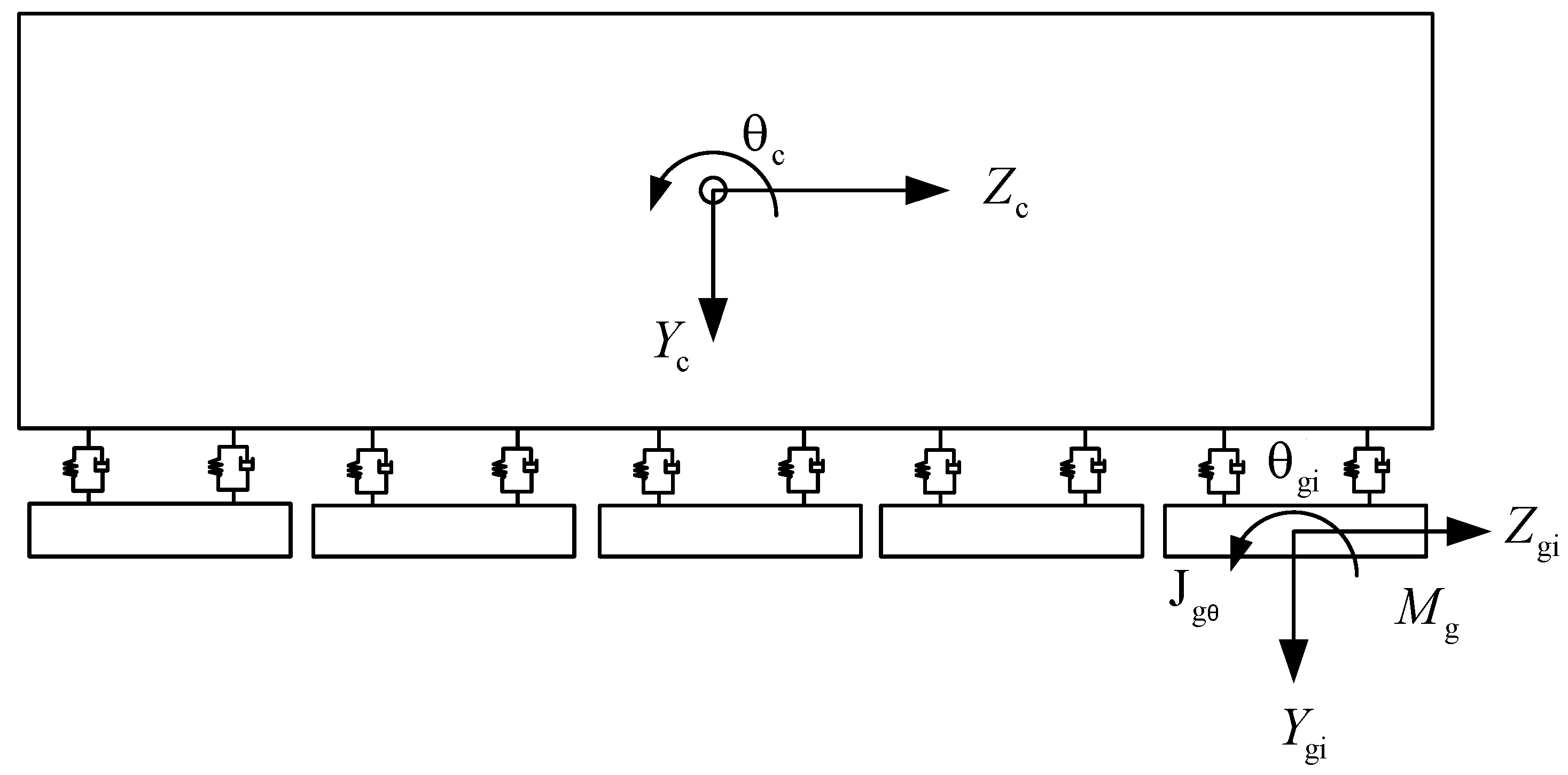
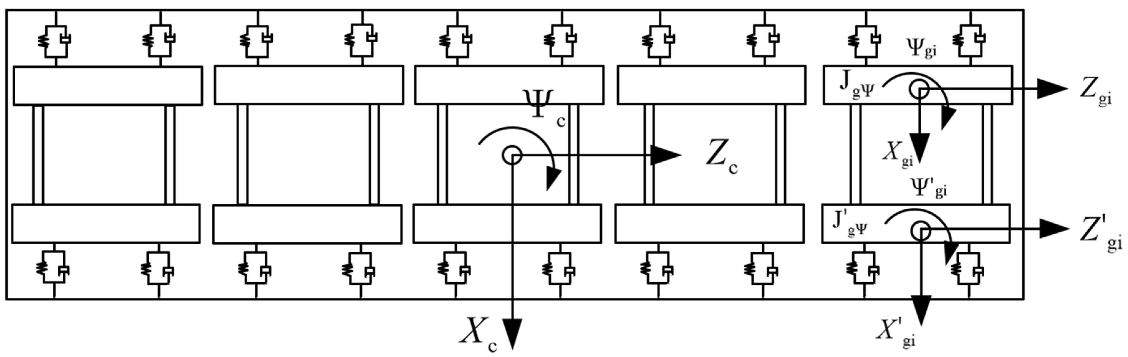
2. System Description

In this study, a simply supported girder bridge with a span arrangement of 10 × 25 m is selected as the research object to investigate the influence of pier stiffness on the dynamic response characteristics of a medium–low-speed maglev vehicle–bridge coupled system. The general elevation of the bridge is illustrated in Figure 1. The main girder adopts a double-track beam structure, which serves dual functions as both the load-bearing component for maglev train operations and the guidance track for the vehicle system. The track beam features a single-cell prestressed concrete box section with the following geometric parameters: section height: 2.1 m, top flange width: 1.3 m, bottom flange width: 1.4 m, and concrete grade: C50. Transverse connection beams are installed at 6 m intervals between the two track beams. For each 25 m span, a total of five transverse connection beams are provided, consisting of two end diaphragms and three intermediate diaphragms.
The typical cross-sectional profiles of the main girders and connecting beams are depicted in Figure 2, respectively. The piers of the bridge are constructed in the form of a “cap beam + pier shaft”, with a solid rectangular concrete cross section. The cap beam is fabricated from C50 concrete, while the pier shaft is composed of C40 concrete. The elevation and cross-section of the pier are illustrated in Figure 3 and Figure 4, respectively. All materials are assumed to be linear elastic, with the elastic modulus E and Poisson’s ratio determined according to the relevant specifications. The structural system employs Rayleigh damping with a damping ratio of 2%.

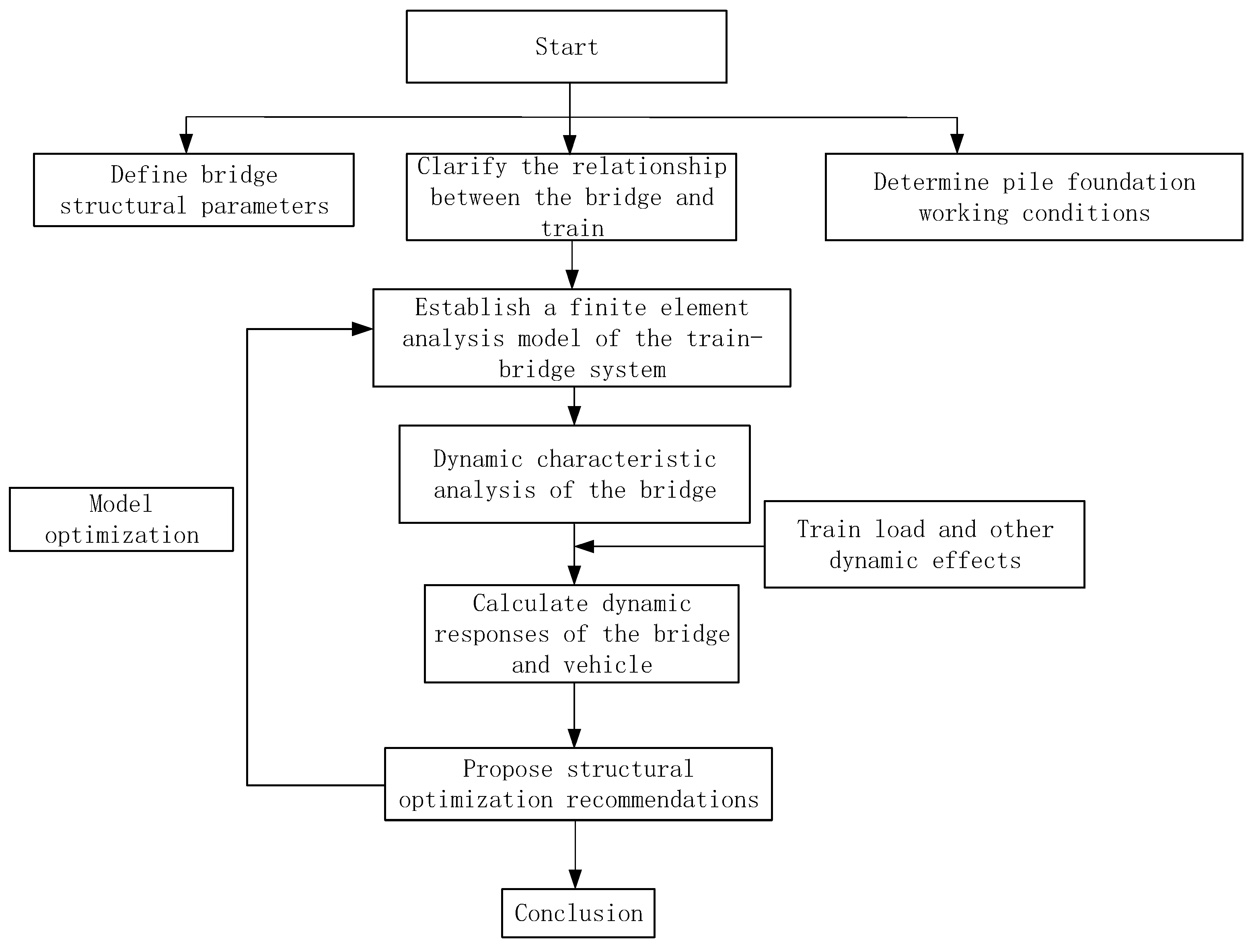
3. Modeling Approach

3.1. The Establishment of Finite Element Model of Bridge and the Calculation and Analysis of Its Natural Vibration Characteristics

In the process of modeling in this paper, space beam elements were used to simulate all components, and the interaction between piles and soil was simulated using the m method. The elastic modulus E, density ρ, Poisson’s ratio μ, and other parameters of all components were set according to the current norms. The finite element analysis model of the 10 × 25 m simply supported beam bridge selected in this paper is shown in Figure 5.
The natural vibration characteristics of a bridge are among the most important parameters for reflecting its dynamic characteristics, and serve as the basis for vehicle–bridge coupled vibration analysis. These characteristics include natural frequencies and mode shapes, which are closely related to the structural configuration, mass distribution, stiffness distribution, and material properties of the bridge. They can be used to evaluate the bridge stiffness and validate the finite element model. Based on the 10 × 25 m simply supported girder bridge model established previously, we calculated and analyzed its natural vibration characteristics. The first three natural frequencies corresponding to lateral bending, vertical bending, and longitudinal vibration modes are summarized in Table 1, while the mode shapes for the first-order lateral bending, vertical bending, and longitudinal vibration are shown in Figure 6, Figure 7 and Figure 8.
As shown in the frequency analysis results, the first vertical bending mode frequency of the 10 × 25 m simply supported beam is 5.319 Hz, which exceeds the minimum requirement of 3.600 Hz (i.e., 90/L, where L = 25 m) specified in the Design Code for Medium and Low Speed Maglev Transportation [35] (hereinafter referred to as the Code). The initial vibration modes are dominated by longitudinal floating displacements, indicating relatively weak longitudinal constraints, which is consistent with the structural characteristics of a simply supported beam bridge. Furthermore, the transverse bending mode appears before the vertical bending mode, suggesting that the bridge’s transverse stiffness is lower than its vertical stiffness.

3.2. Track Irregularity and Train Grouping

3.2.1. Track Irregularity

This study focuses on the dynamic behavior of simply supported beam bridges for medium- and low-speed maglev (MLSM) transportation systems. The bridge is designed to accommodate MLSM trains with a maximum operating speed of 100 km/h. To account for track irregularities, the German low-interference spectrum is applied based on the vehicle–bridge interaction parameters. The corresponding power spectral density (PSD) function is calculated as follows:
Longitudinal Irregularity:
S a Ω = A a Ω c 2 Ω 2 + Ω r 2 Ω 2 + Ω c 2
Vertical Irregularity:
S v Ω = A v Ω c 2 Ω 2 + Ω r 2 Ω 2 + Ω c 2
Lateral Irregularity:
S c Ω = A v b 2 Ω c 2 Ω 2 Ω 2 + Ω r 2 Ω 2 + Ω c 2 Ω 2 + Ω s 2
In the above formula, the units of S v ( Ω ) and S a ( Ω ) are m2/(rad/m); the unit of S c ( Ω ) is 1/(rad/m); Ω is the spatial angular frequency; the unit of Ω is rad/m; Ω c , Ω r , and Ω s are the truncated frequency and values of these variables are Ω c = 0.8246 rad/m, Ω r = 0.0206 rad/m, and Ω s = 0.438 rad/m; A a and A v are roughness constants, where A a = 2.119 × 10⁻⁷ cm2·rad/m and A v = 4.031 × 10⁻⁷ cm2·rad/m; and b is half of the distance of the left and right rolling circles, taking 0.75 m.

3.2.2. Train Mode Shape

In this paper, three medium–low-speed maglev trains are assembled with a design speed of 100 km/h. The train mode shape and calculation conditions are shown in Table 2.

3.3. Establishment of Spatial Vibration Analysis Model for Medium–Low-Speed Maglev Train

3.3.1. Basic Assumption

The medium–low-speed maglev train system is structurally composed of the following two primary subsystems: the carbody and the levitation frame. A standard train mode shape adopts a three-unit configuration, with each unit equipped with five levitation frames. Interconnection between the carbody and levitation frame is achieved through air spring. Considering the system complexity and operational characteristics at medium–low speeds, establishing a fully detailed dynamic model faces both theoretical and computational difficulties, particularly for the practical engineering analysis of such systems. Thus, this study utilizes a simplified train model for dynamic behavior investigation. To maintain the engineering relevance and computational reliability of the simplified modeling approach, the following fundamental assumptions are applied:
  • Both structural components (carbody and levitation frame) are considered as rigid bodies, with their elastic demode shapes disregarded.
  • Suspension elements are represented as linear springs, accompanied by equivalent viscous damping for energy dissipation modeling.
  • System dynamics are analyzed within the small vibration range.
  • Longitudinal vibrations along the guideway direction are deemed insignificant for medium–low-speed operations.
  • The dynamic interaction from guideway longitudinal vibrations is not included in the current analysis scope.

3.3.2. Spatial Vibration Analysis Model of Medium–Low-Speed Maglev Train

Based on the aforementioned modeling assumptions, a three-dimensional vibration analysis model of the train is developed. A schematic representation of the simplified train model is illustrated in Figure 9, Figure 10 and Figure 11. In this configuration, each train unit comprises one carbody and five levitation frames. Each levitation frame consists of two symmetrical levitation modules interconnected via linear spring elements. The proposed model represents the train system using 11 rigid bodies, with each body possessing the following five degrees of freedom (DOFs): vertical displacement (sinking and floating), lateral displacement (sway), roll rotation, pitch rotation, and yaw rotation. This formulation results in a total of 55 degrees of freedom for the complete train model. The detailed parameter specifications are provided in Table 3.

3.4. Motion Equation of Medium- and Low-Speed Maglev Train

In this paper, the motion equation of a maglev train is established based on the principle of the constant total potential energy of an elastic system. Firstly, based on the energy method, the total space vibration potential energy v of the maglev train is listed and its variational δ v = 0 is obtained. Then, the mass matrix [ M v ] , stiffness matrix [ K v ] , damping matrix [ C v ] , load matrix P v , and displacement matrix of the train system δ v are obtained according to the law of “matching number and seating” [36,37,38]. Finally, the motion equation of maglev train is established as follows Figure 12:
M v δ ¨ v + C v δ ˙ v + K v δ v = P v
The flowchart of the vehicle–bridge coupled interaction analysis is illustrated as follows:

4. Calculation Results and Analysis of Dynamic Response of Medium–Low-Speed Maglev Train–Bridge System

The dynamic performance of a train is primarily assessed from the following two perspectives: safety and ride comfort. A typical safety concern is derailment risk. For conventional wheel–rail trains, operation relies on continuous contact between the wheels and the track, which may lead to potential hazards such as wheel climb or wheel flange derailment. However, for the medium–low-speed maglev train investigated in this study, derailment is inherently avoided due to its “rail-embracing” suspension mechanism. Ride comfort is evaluated based on the running stability of the train, which is quantified by the lateral and vertical vibration accelerations of the carbody during operation. Lower carbody vibration accelerations correspond to improved running smoothness, thereby enhancing passenger comfort.

4.1. Calculation Results and Analysis of Bridge Dynamic Response

When the train traversed the 10 × 25 m simply supported beam bridge at speeds ranging from 60 to 120 km/h, the dynamic response characteristics of the bridge were analyzed. The results are summarized in Table 4 and further visualized as a line chart in Figure 13.
Based on the dynamic response analysis of the 10 × 25 m simply supported beam bridge under varying operational conditions, the maximum lateral displacement of the main girder reached 1.55 mm under the single/double-track 110 km/h scenario, while the peak vertical displacement of 3.27 mm occurred under the double-track 90 km/h scenario. The transverse displacements showed negligible correlations with train speed and no discernible trend, whereas vertical displacements were significantly influenced by track configuration, with double-track conditions producing markedly higher values than single-track scenarios. Train speed demonstrated minimal impact on vertical displacements, similarly lacking a clear trend. Both the lateral and vertical accelerations of the main girder were highly sensitive to train speed, though no consistent pattern emerged. For pier top lateral displacements, pier top lateral accelerations, and the angle of beam end (lateral/vertical), the parameters were largely insensitive to train speed and showed no observable regularity.

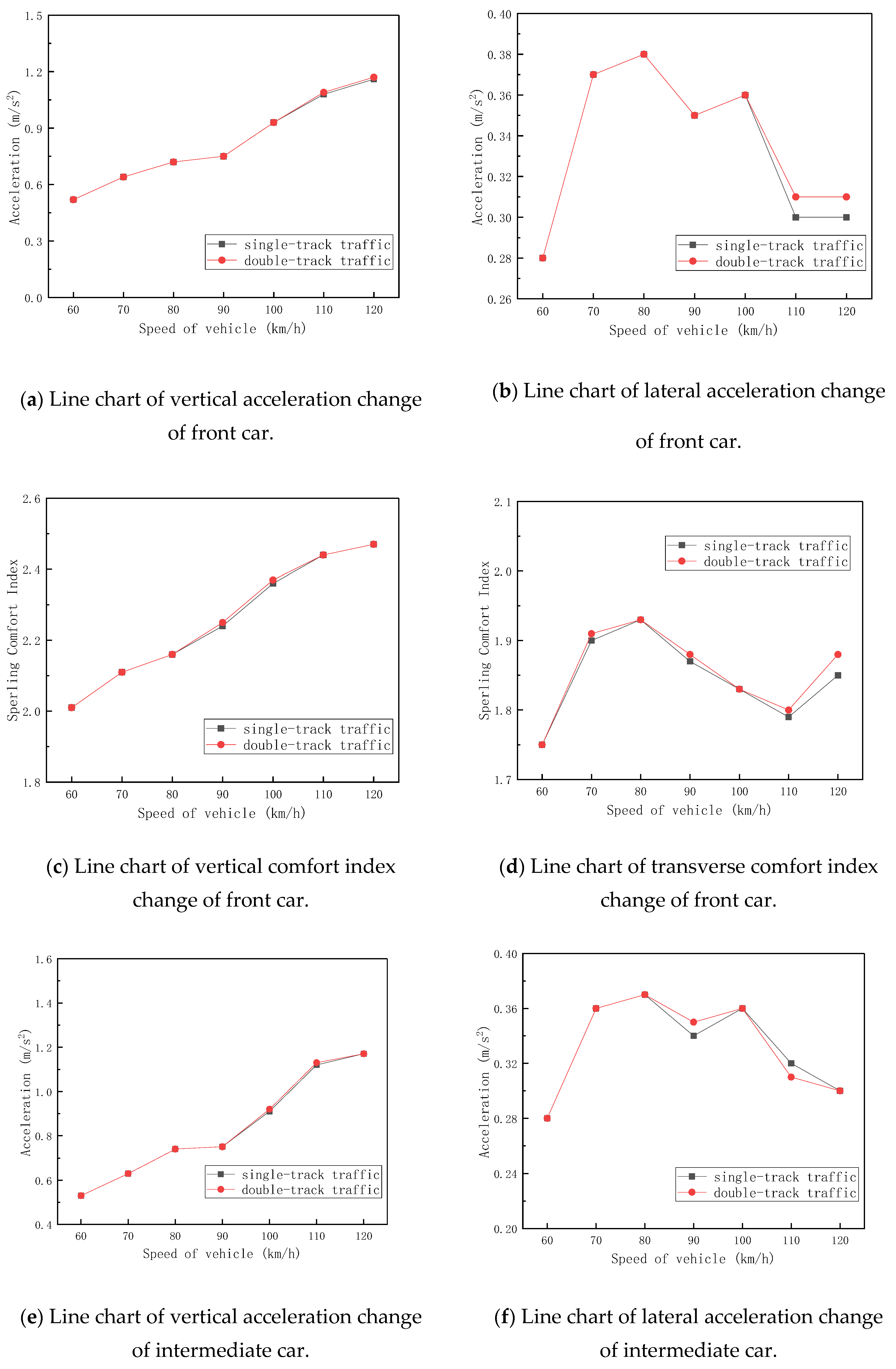
4.2. Calculation Results and Analysis of Train Dynamic Response

Considering when trains traversed the 10 × 25 m simply supported beam bridge at speeds ranging from 60 to 120 km/h, the train dynamic response characteristics are summarized in Table 5 and further visualized in the line chart presented in Figure 14.
As shown in the above charts, when the train traversed the bridge at speeds ranging from 60 to 120 km/h, the peak lateral acceleration of the train reached 0.38 m/s2 under the single/double-track 80 km/h operational condition, complying with the specification requirement of lateral vibration acceleration ≤1.0 m/s2. The maximum vertical acceleration of 1.17 m/s2 occurred at 120 km/h under single/double-track conditions, satisfying the standard requirement of vertical vibration acceleration ≤1.3 m/s2. Both the lateral and vertical Sperling indices remained below 2.5 across all speed ranges, indicating “excellent” levels of ride comfort in both directions. While train acceleration in both directions demonstrated significant speed dependence, the vertical acceleration exhibited a clear increasing trend with speed, whereas the lateral acceleration showed no distinct speed-related pattern. At identical speeds, the lateral and vertical accelerations showed minimal variation between the leading and middle cars. The vertical ride comfort deteriorated with an increasing speed, while the lateral ride comfort maintained no consistent speed-dependent relationship.

5. Influence of Lateral Stiffness Variation of Bridge on Dynamic Response of Maglev Vehicle–Bridge System

Long-span beam bridges have relatively large spans, and their main girders are prone to significant demode shape under dynamic loads. Particularly for maglev vehicles, which require strict track regularity, such bridges demand higher stiffness requirements. For medium-to-long-span, low-to-medium-speed maglev continuous beam bridges, the lack of established standards and limited reference engineering cases has resulted in no unified stiffness criteria. Evaluating these bridges using the stiffness limits for high-speed maglev bridges would inevitably lead to material waste. Therefore, investigating the stiffness parameters of such bridges is crucial for determining appropriate stiffness values that meet operational requirements.
For long-span continuous beam bridges, the stiffness of both the main girder and piers primarily determines the overall structural stiffness. In this study, we adopted a parametric approach by varying the elastic moduli of these components. The elastic modulus was adjusted by −50%, −25%, ±0%, +25%, and +50% to modify the corresponding stiffness matrices. Using a maglev vehicle as the study subject, we calculated the wheel–axle dynamic responses at speeds of 60, 70, 80, 90, 100, 110, and 120 km/h under various operating conditions, analyzing how different parameters affected the dynamic wheel–axle responses.

5.1. Influence of Lateral Line Stiffness of Pier Top on Natural Vibration Characteristics of Bridge

Under the five defined pier top lateral stiffness conditions, a finite element model of the complete 10 × 25 m simply supported beam bridge, including substructures, was established, and its modal characteristics were analyzed. The fundamental natural frequencies for lateral bending, vertical bending, and longitudinal floating modes under each condition are summarized in Table 6.
The analysis of the chart demonstrates that with a constant vertical linear stiffness at the pier top and an increasing lateral linear stiffness from −50% to +50%, the bridge’s fundamental frequencies exhibited distinct trends: the lateral bending frequency increased progressively by 61.8% from 0.841 Hz to 1.361 Hz, while the vertical bending and longitudinal floating frequencies decreased by 2.3% from 5.343 Hz to 5.218 Hz and 29.2% from 1.109 Hz to 0.785 Hz, respectively.

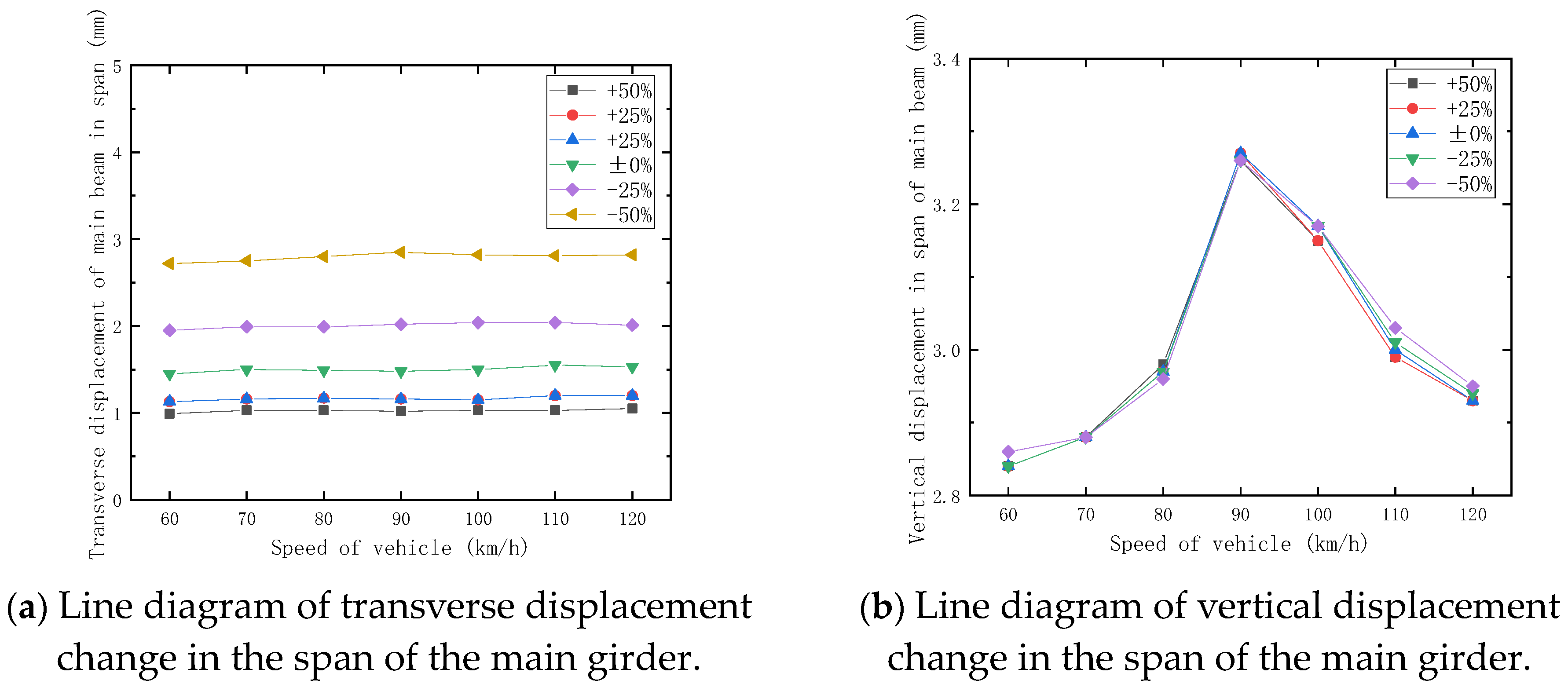
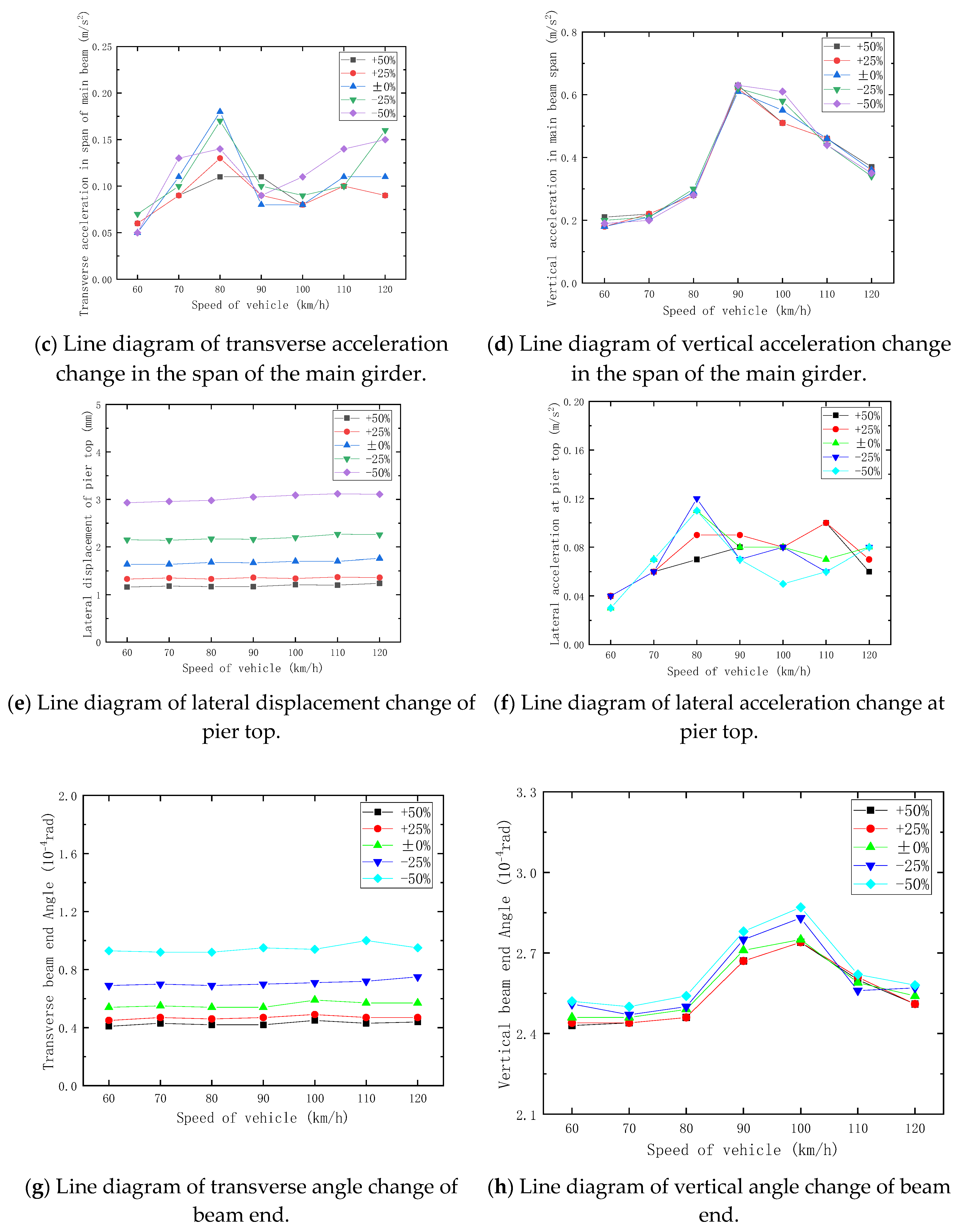
5.2. Influence of Lateral Line Stiffness of Pier Top on Dynamic Response of Bridge

A full-bridge finite element model incorporating the five defined pier top lateral stiffness conditions was developed to analyze the vehicle–bridge coupled vibrations under double-track train operations at speeds ranging from 60 to 120 km/h. The computed bridge dynamic responses are presented in Figure 15.
Analysis of the data in Figure 15 reveals that all bridge dynamic responses complied with specification requirements as the pier top lateral stiffness increased from −50% to +50% while vertical stiffness remained constant. The main girder exhibited a 63.2% reduction in lateral displacement (from 2.85 mm to 1.05 mm) with minimal vertical displacement variation, demonstrating that an increased lateral stiffness significantly enhanced lateral stability while having negligible impact on vertical stability. Although the main girder’s lateral acceleration showed no consistent pattern, its stable vertical acceleration indicates a consistent vertical dynamic performance. The pier top displayed a 60.3% decrease in lateral displacement (from 3.12 mm to 1.24 mm), while its lateral acceleration remained irregular. Beam-end rotations showed a 55% reduction in transverse angle (from 1.0 rad to 0.45 rad) with stable vertical angles, confirming that an increased pier top lateral stiffness effectively constrained transverse rotation without significantly affecting vertical rotation.

5.3. Influence of Lateral Line Stiffness of Pier Top on Train Dynamic Response

A full-bridge finite element model considering five pier-top lateral stiffness conditions was established to investigate the vehicle–bridge coupled vibrations under double-track train operations at speeds ranging from 60 to 120 km/h. The corresponding train dynamic responses are presented in Figure 16.
The analysis demonstrates that the peak lateral and vertical vibration accelerations of the train complied with the specified limits under all investigated operating conditions, achieving an excellent ride comfort performance. Furthermore, the study reveals that pier top lateral stiffness exhibited a negligible influence on both lateral and vertical vibration accelerations of the train.

6. Conclusions

This study investigates a 10 × 25 m simply supported rail beam bridge using proprietary computational software to analyze its natural vibration characteristics and vehicle–bridge coupled dynamics. The research specifically examines how pier top lateral stiffness influences the dynamic behavior of medium–low-speed maglev train–bridge systems through comprehensive spatial dynamic response calculations under various operational scenarios. The principal findings are as follows:
(1)
The dynamic analysis of the 10 × 25 m simply supported beam bridge under various operating conditions shows that the lateral displacement of the main girder, lateral displacement and acceleration of the pier top, and lateral and vertical angle of beam end have little correlation with train speed (60–120 km/h) and show no clear pattern under single- or double-track conditions. However, the vertical displacement is significantly affected by track configuration, with the main girder’s vertical displacement being notably greater under double-track conditions compared to single-track conditions, while remaining largely unaffected by speed variations and showing no distinct regularity.
(2)
The pier top lateral stiffness exhibits a significant influence on the bridge’s dynamic characteristics. The lateral bending fundamental frequency increases progressively with stiffness enhancement, showing 61.8% growth when the lateral stiffness varies from −50% to +50%. Conversely, the longitudinal floating fundamental frequency decreases gradually, with a 29.2% reduction over the same stiffness variation range. These variations occur while the vertical linear stiffness at the control pier top remains constant throughout the analysis. Given the pronounced sensitivity of dynamic frequencies to lateral stiffness, precise stiffness control during construction is critical. While a higher lateral stiffness enhances transverse vibration resistance, its detrimental impact on longitudinal performance necessitates a balanced design approach, particularly in wind-prone regions, to mitigate resonance risks. These findings highlight the importance of early-stage parametric stiffness optimization to ensure structural safety and performance.
(3)
The pier top lateral linear stiffness significantly affects the following three key structural responses: the lateral displacement of the main girder, the lateral displacement of the pier top, and the lateral angle of beam end. As the lateral stiffness increases from −50% to +50% while maintaining a constant vertical linear stiffness at the control pier top, these responses demonstrate substantial reductions: a 63.2% decrease in main girder lateral displacement, a 60.3% decrease in pier top lateral displacement, and a 55% decrease in the angle of beam end.
(4)
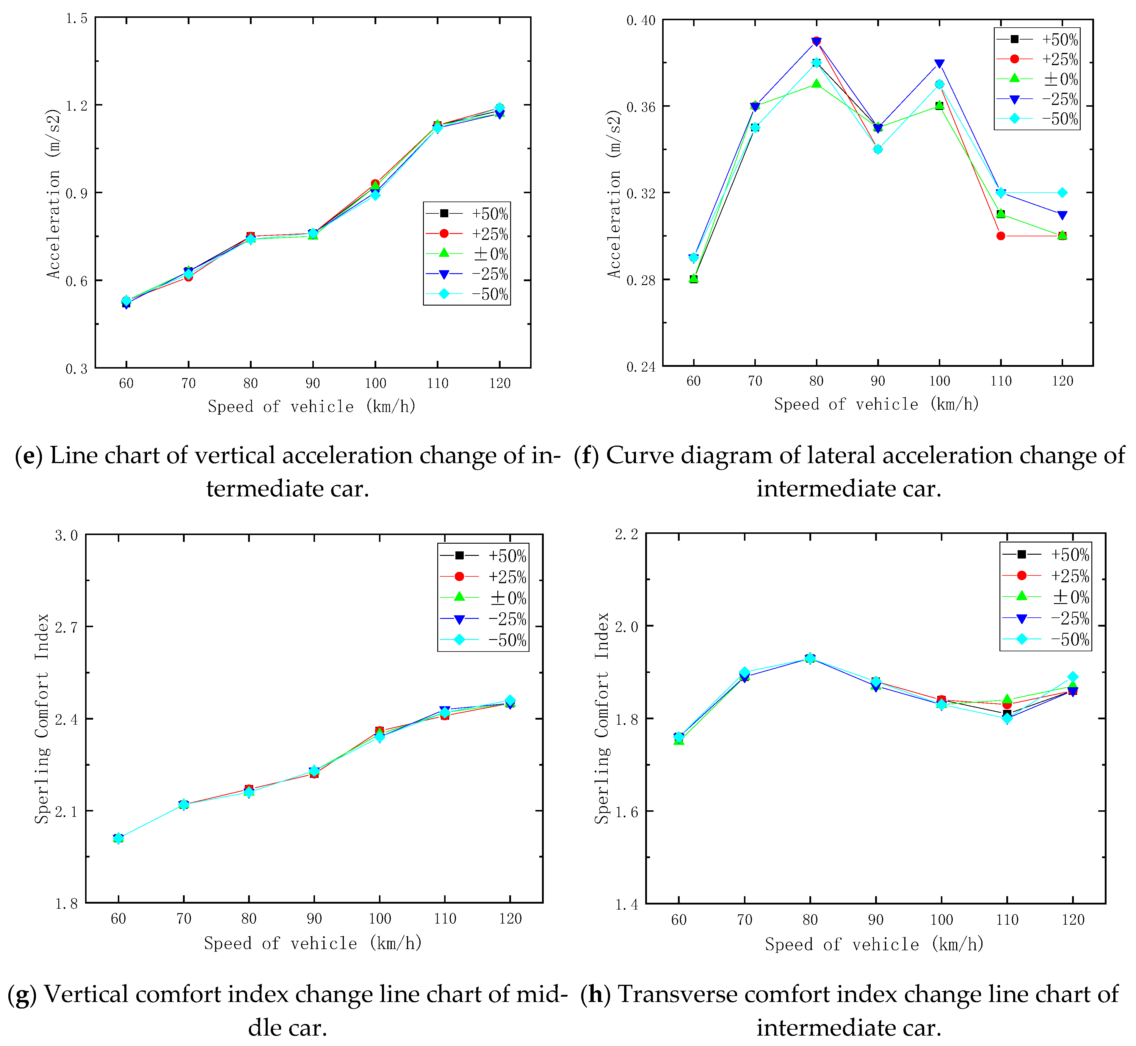
Within the ±50% variation range of pier top lateral stiffness, the study reveals the following three key findings: the lateral vibration acceleration of the main girder shows no monotonic relationship with the pier top linear stiffness; the vertical vibration acceleration of the main girder remains relatively stable, with insignificant variations; and both transverse and vertical vibration accelerations exhibit minimal changes overall. Furthermore, the pier top lateral line stiffness demonstrates a negligible influence on the train’s lateral and vertical vibration accelerations.
(5)
According to the research findings, the pier top lateral stiffness has an insignificant impact on the lateral vibration acceleration of the main girder and also exerts minimal influence on the lateral and vertical vibration accelerations of the train. Therefore, in the process of code revision, it is advisable to consider relaxing the restrictions on the main girder’s vibration acceleration caused by variations in pier top lateral stiffness. Moreover, the provisions related to train vibration acceleration can also be optimized based on this conclusion, reducing the over-regulation of train vibration acceleration due to pier top lateral stiffness factors.

Author Contributions

Conceptualization, Y.C., X.G., H.M. and J.L.; methodology, Y.C.; software, Y.C.; validation, Y.C., X.G. and H.M.; formal analysis, Y.C.; investigation, Y.C.; resources, Y.C.; data curation, Y.C.; writing—original draft preparation, Y.C.; writing—review and editing, Y.C.; visualization, Y.C. and X.G.; supervision, X.G., H.M. and J.L.; project administration, Y.C.; funding acquisition, Y.C. All authors have read and agreed to the published version of the manuscript.

Funding

This research received no external funding.

Institutional Review Board Statement

Not applicable.

Informed Consent Statement

Not applicable.

Data Availability Statement

All data included in this study are available upon request by contact with the corresponding author.

Conflicts of Interest

Hongwei Mao is employed by China Railway Engineering Design and Consulting Group Co. Yanghua Cui is affiliated with the School of Civil Engineering, Central South University, and China Railway South Investment Group Co. The remaining authors declare that the research was conducted in the absence of any commercial or financial relationships that could be construed as a potential conflict of interest.

References

  1. Han, H.-S.; Kim, D.-S. Magnetic Levitation; Springer: Dordrecht, The Netherlands, 2016; 247p. [Google Scholar]
  2. Liu, Z.; Long, Z.; Li, X. Maglev Trains; Springer: Berlin/Heidelberg, Germany, 2015. [Google Scholar]
  3. Sinha, P.K. Electromagnetic Suspension Dynamics & Control; Peter Peregrinus Ltd.: London, UK, 1987. [Google Scholar]
  4. Guobin, L.; Xiongwei, S. Application and further development of Maglev transportation in China. Mod. Transp. Syst. Technol. 2018, 4, 36–43. [Google Scholar]
  5. Kim, M.; Jeong, J.H.; Lim, J.; Kim, C.H.; Won, M. Design and control of levitation and guidance systems for a semi-high-speed maglev train. J. Electr. Eng. Technol. 2017, 12, 117–125. [Google Scholar] [CrossRef]
  6. Kwon, S.D.; Lee, J.S.; Moon, J.W.; Kim, M.Y. Dynamic interaction analysis of urban transit maglev vehicle and guideway suspension bridge subjected to gusty wind. Eng. Struct. 2008, 30, 3445–3456. [Google Scholar] [CrossRef]
  7. Nagashima, K. Update on basic research into superconducting maglev and research on application of maglev technology to conventional railway systems. Q. Rep. RTRI 2020, 61, 11–15. [Google Scholar] [CrossRef] [PubMed]
  8. Wang, S.M.; Ni, Y.Q.; Sun, Y.G.; Lu, Y.; Duan, Y.F. Modelling dynamic interaction of maglev train–controller–rail–bridge system by vector mechanics. J. Sound Vib. 2022, 533, 117023. [Google Scholar] [CrossRef]
  9. Li, X.; Geng, J.; Wang, D. Dynamic responses of low–medium speed maglev train–simply supported beam interaction system. Urban Rail Transit 2017, 3, 136–141. [Google Scholar] [CrossRef]
  10. Zhang, M.; Yuan, C.; Ma, W.; Luo, S. Effect of suspension form on the vehicle-bridge coupled vibration of the maglev vehicle. Int. J. Veh. Mech. Mobil. 2024, 62, 511–532. [Google Scholar] [CrossRef]
  11. Zhou, F.; Li, X. Coupled Dynamics Modeling and Validation of Maglev Vehicle and Bridge Systems. Actuators 2025, 14, 107. [Google Scholar] [CrossRef]
  12. Cao, S.; Liu, C.; Wang, S.; Sun, L. Analysis of vibrational stability, bifurcation and resonance characteristics of the maglev train-bridge coupling system. Nonlinear Dyn. 2025, 113, 16135–16159. [Google Scholar] [CrossRef]
  13. Tian, X.; Xiang, H.; Li, Y. Modeling and analyzing of high-speed maglev train-bridge systems considering centrifugal force induced by bridge vertical demode shape. Structures 2025, 73, 108240. [Google Scholar] [CrossRef]
  14. Xia, W.; Zeng, J.; Dou, F.; Long, Z. Method of combining theoretical calculation with numerical simulation for analyzing effects of parameters on the maglev vehicle-bridge system. IEEE Trans. Veh. Technol. 2021, 70, 2250–2257. [Google Scholar] [CrossRef]
  15. Deng, Z.; Li, J.; Wang, H.; Li, Y.; Zheng, J. Dynamic simulation of the vehicle/bridge coupled system in high-temperature superconducting maglev. Comput. Sci. Eng. 2019, 21, 60–71. [Google Scholar] [CrossRef]
  16. Li, Y.-X.; Yu, Z.-W.; Xu, L. Stochastic resonance analysis of a coupled high-speed maglev vehicle-bridge coupled system under bounded noise. Sci. Rep. 2023, 13, 7519. [Google Scholar] [CrossRef] [PubMed]
  17. Li, M.; Ma, W.-h.; Gong, J.-h.; Li, W.-l.; Gao, D.-g.; Luo, S.-h. Dynamic performance test of medium and low speed maglev vehicle-bridge coupled system. J. Traffic Transp. Eng. 2022, 22, 141–154. [Google Scholar]
  18. Huang, F.; Wang, J.; Teng, N.; Cheng, B. Coupled vibration of low-medium-speed maglev vehicle-guideway system on isolated bridge with lead rubber bearings. Adv. Struct. Eng. 2024, 27, 2391–2408. [Google Scholar] [CrossRef]
  19. Song, Y.; Lin, G.; Ni, F.; Xu, J.; Chen, C. Study on Coupled Vertical Vehicle-Bridge Dynamic Performance of Medium and Low-Speed Maglev Train. Appl. Sci. 2021, 11, 5898. [Google Scholar] [CrossRef]
  20. Wang, L.; Bu, X.; Hu, P.; Han, Y.; Cai, C. Dynamic reliability analysis of running safety and stability of a high-speed maglev train on a guideway bridge. Int. J. Struct. Stab. Dyn. 2024, 24, 2450043. [Google Scholar] [CrossRef]
  21. Wang, L.; Bu, X.; Shen, Y.; Han, Y.; Hu, P.; Cai, C. Effect of control time delay on high-speed maglev vehicle-bridge-wind system. J. Vib. Control. 2025, 10775463251321726. [Google Scholar] [CrossRef]
  22. Bu, X.; Wang, L.; Han, Y.; Liu, H.; Hu, P.; Cai, C.S. Dynamic model of high-speed maglev train-guideway bridge system with a nonlinear suspension controller. Adv. Struct. Eng. 2024, 27, 1328–1348. [Google Scholar] [CrossRef]
  23. Bu, X.; Wang, L.; Han, Y.; Liu, H.; Hu, P.; Cai, C. A fast multi-objective optimization method for control parameters of high-speed maglev vehicle-bridge system. Int. J. Struct. Stab. Dyn. 2024, 2550206. [Google Scholar] [CrossRef]
  24. Li, X.; Wang, D.; Liu, D.; Xin, L.; Zhang, X. Dynamic analysis of the interactions between a low-to-medium-speed maglev train and a bridge: Field test results of two typical bridges. Proc. Inst. Mech. Eng. Part F J. Rail Rapid Transit 2018, 232, 2039–2059. [Google Scholar] [CrossRef]
  25. Li, D.; Huang, J. Hierarchical model updating for high-speed maglev vehicle/guideway coupled system based on multi-objective optimization. Front. Struct. Civ. Eng. 2024, 18, 788–804. [Google Scholar] [CrossRef]
  26. Yang, X.L.; Li, L.; Yin, J.H. Seismic and static stability analysis for rock slopes by a kinematical approach. Geotechnique 2004, 54, 543–549. [Google Scholar] [CrossRef]
  27. Yang, X.L.; Yin, J.H. Upper bound solution for ultimate bearing capacity with a modified Hoek–Brown failure criterion. Int. J. Rock Mech. Min. Sci. 2005, 42, 550–560. [Google Scholar] [CrossRef]
  28. Yang, X.L.; Wang, J.M. Ground movement prediction for tunnels using simplified procedure. Tunn. Undergr. Space Technol. 2011, 26, 462–471. [Google Scholar] [CrossRef]
  29. Yang, X.L.; Yin, J.H. Slope stability analysis with nonlinear failure criterion. J. Eng. Mech. 2004, 130, 267–273. [Google Scholar] [CrossRef]
  30. Hou, L.; Liang, S.; Chi, M. Research on vehicle-rail coupling vibration at turnout and suppression method of medium and low speed maglev vehicle. Electr. Drive Locomot. 2024, 5, 49–55. [Google Scholar]
  31. Tian, X.F.; Xiang, H.Y.; Chen, X.L.; Li, Y.L. Dynamic response analysis of high-speed maglev train-guideway system under crosswinds. J. Cent. South Univ. 2023, 30, 2757–2771. [Google Scholar] [CrossRef]
  32. Shan, J.T.; Wu, Y.M.; Yang, X.L. Three-dimensional stability of two-step slope with crack considering temperature effect on unsaturated soil. J. Cent. South Univ. 2025, 32, 1060–1079. [Google Scholar] [CrossRef]
  33. Yang, X.L.; Huang, F. Collapse mechanism of shallow tunnel based on nonlinear Hoek–Brown failure criterion. Tunn. Undergr. Space Technol. 2011, 26, 686–691. [Google Scholar] [CrossRef]
  34. Guo, X.; Liu, J.; Cui, R. Research on Train-Induced Vibration of High-Speed Railway Station with Different Structural Forms. Materials 2024, 17, 4387. [Google Scholar] [CrossRef] [PubMed]
  35. CJJ/T 262–2017; Code for Design of Medium and Low Speed Maglev Transit. China Architecture & Building Press: Beijing, China, 2017.
  36. Zeng, Q. The principle of total potential energy with stationary value in elastic system dynamics. J. Huazhong Univ. Sci. Technol. 2000, 28, 1–3+14. [Google Scholar]
  37. Zeng, Q.Y.; Yan, G.P. The “set-in-right-position” rule forming structural method for space analysis of truss bridges. J. China Railw. Soc. 1986, 8, 48–59. [Google Scholar]
  38. Zeng, Q.Y.; Guo, X.R. Theory and Application of Vibration Analysis of Time-Varying Systems on Train Bridges; China Railway Publishing House: Beijing, China, 1999. [Google Scholar]
Figure 1. Elevation of 10 × 25 m simply supported beam bridge (unit: cm).
Applsci 15 06628 g001
Figure 2. Section diagrams of track beam and end/middle beam (unit: cm).
Applsci 15 06628 g002
Figure 3. Elevation of pier (unit: cm).
Applsci 15 06628 g003
Figure 4. Section of pier top and pier body (unit: cm).
Applsci 15 06628 g004
Figure 5. Finite element analysis model of 10 × 25 m simply supported beam bridge.
Applsci 15 06628 g005
Figure 6. Transverse bending mode of the first step of the 10 × 25 m simply supported beam bridge.
Applsci 15 06628 g006
Figure 7. Vertical bending mode of the first order of 10 × 25 m simply supported beam bridge.
Applsci 15 06628 g007
Figure 8. Longitudinal floating mode of the first order of 10 × 25 m simply supported beam bridge.
Applsci 15 06628 g008
Figure 9. Elevation of maglev train.
Applsci 15 06628 g009
Figure 10. Schematic diagram of maglev train overlooking and shaking head angular displacement.
Applsci 15 06628 g010
Figure 11. Vertical spring of maglev train.
Applsci 15 06628 g011
Figure 12. Flowchart of vehicle–bridge coupled interaction analysis.
Applsci 15 06628 g012
Figure 13. Trend diagrams of bridge dynamic response.
Applsci 15 06628 g013aApplsci 15 06628 g013b
Figure 14. Dynamic response trend diagrams of train.
Applsci 15 06628 g014aApplsci 15 06628 g014b
Figure 15. Dynamic response trend diagrams of bridge.
Applsci 15 06628 g015aApplsci 15 06628 g015b
Figure 16. Dynamic response trend diagrams of train.
Applsci 15 06628 g016aApplsci 15 06628 g016b
Table 1. Summary of natural vibration frequency of 10 × 25 m simply supported beam bridge.
Structural Mode ShapeThe Order of the Mode ShapeNatural Frequency (Hz)Characteristics of the Mode Shapes of a Structure
Lateral bending of the girder91.139Lateral flexural behavior of pier-girder system
111.268
121.403
Vertical flexure of the girder195.319Vertical flexural vibration of pier-girder assembly
205.340
215.387
Longitudinal deflection10.916Longitudinal floating behavior of pier–girder system
20.918
30.940
Table 2. List of mode shape and calculation conditions of medium-low speed maglev train.
Train TypeTrain Mode ShapeCalculated Speed (km/h)Track Irregularity
Medium–low-speed
maglev train
Three cars in groups
(Lead car + middle car + lead car)
60 70 80 90
100 110 120
The German low-interference spectrum
Table 3. Summary table of freedom of maglev train model.
Degree of FreedomVertical DisplacementLateral DisplacementYaw RotationPitch RotationRoll Rotation
Maglev train body Y c X c Ψ c θ c φ c
Left suspension module i (i = 1, 2, 3, 4, 5) Y g i X g i Ψ g i θ g i φ g i
Right suspension module i (i = 1, 2, 3, 4, 5) Y g i X g i Ψ g i θ g i φ g i
Table 4. Summary of maximum dynamic response of bridge.
Working ConditionSpeed of Vehicle
(km/h)
Impact CoefficientMid-Span Displacement of Main Girder
(mm)
Main Girder Span Acceleration (m/s2)Lateral Displacement of Pier Top
(mm)
Lateral Acceleration at Pier Top
(m/s2)
Angle of Beam End (10−4 rad)
HorizontalVerticalHorizontalVerticalHorizontalVertical
Single track601.031.472.010.050.181.650.030.532.43
701.041.502.030.110.211.650.070.532.41
801.061.492.070.140.231.630.090.532.41
901.161.492.270.080.451.640.070.532.68
1001.131.502.210.090.551.630.080.562.75
1101.071.552.080.110.421.650.080.562.47
1201.051.542.060.090.361.680.060.562.46
Double track601.011.452.840.050.181.640.030.542.46
701.021.502.880.110.211.640.070.552.46
801.061.492.970.180.291.680.110.542.49
901.161.483.270.080.611.670.080.542.71
1001.121.503.170.080.551.700.080.592.75
1101.061.553.000.110.461.700.070.572.59
1201.041.532.930.110.361.760.080.572.54
Table 5. Summary of maximum train dynamic response.
Working ConditionSpeed of Vehicle
(km/h)
Lead CarMiddle Car
Vertical Acceleration (m/s2)Lateral Acceleration (m/s2)Sperling Comfort IndexVertical Acceleration (m/s2)Lateral Acceleration (m/s2)Sperling Comfort Index
HorizontalVerticalHorizontalVertical
Single track600.520.282.011.750.530.282.011.76
700.640.372.111.900.630.362.121.89
800.720.382.161.930.740.372.171.93
900.750.352.241.870.750.342.231.87
1000.930.362.361.830.910.362.351.83
1101.080.302.441.791.120.322.421.80
1201.160.302.471.851.170.302.451.86
Double track600.520.282.011.750.530.282.011.75
700.640.372.111.910.630.362.121.89
800.720.382.161.930.740.372.161.93
900.750.352.251.880.750.352.231.87
1000.930.362.371.830.920.362.351.83
1101.090.312.441.801.130.312.421.84
1201.170.312.471.881.170.302.451.87
Table 6. Comparison of natural vibration frequencies of 10 × 25 m simply supported beam bridges under different working conditions.
Mode ShapeFundamental Lateral Flexural ModeFundamental Vertical Flexural ModeFundamental Longitudinal Floating Mode
ConditionModeFrequency (Hz)ModeFrequency (Hz)ModeFrequency (Hz)
+50%101.361215.21810.785
+25%101.245225.25010.785
±0%91.139195.31910.916
−25%21.005205.33910.939
−50%10.841225.34341.109
Disclaimer/Publisher’s Note: The statements, opinions and data contained in all publications are solely those of the individual author(s) and contributor(s) and not of MDPI and/or the editor(s). MDPI and/or the editor(s) disclaim responsibility for any injury to people or property resulting from any ideas, methods, instructions or products referred to in the content.

