
Research on the Dynamic Behavior of “Building-Bridge Integrated” Railway Bridge-Type Station with Setting the Structural Joints on the Mainline

Abstract
1. Introduction
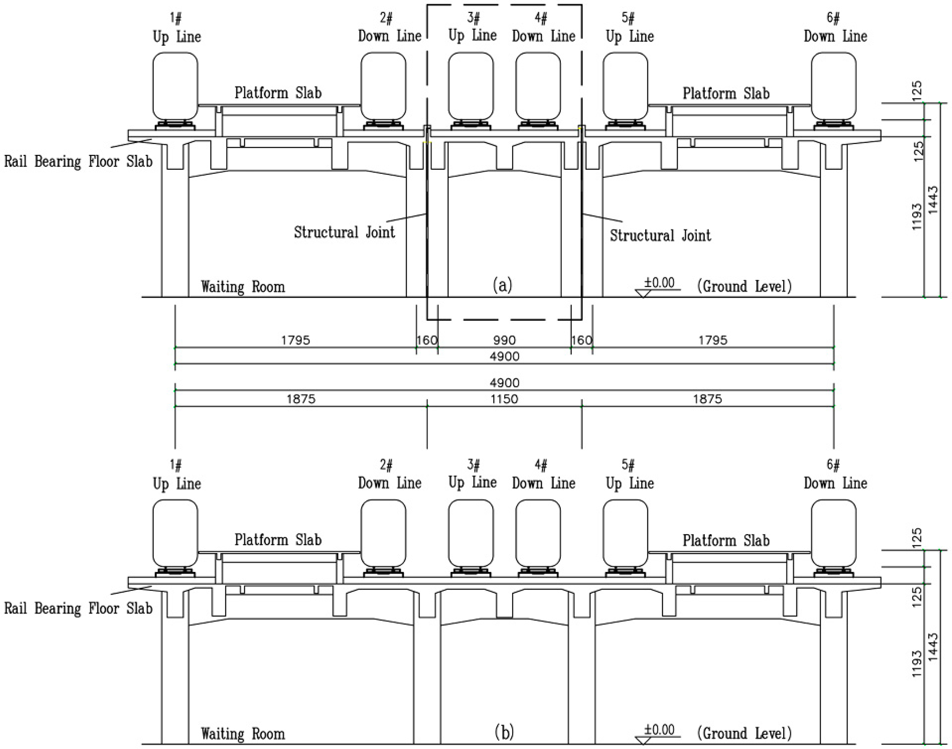
2. Project Overview
3. Simulation and Analysis Model of Train-Track-Station Coupled Vibration
3.1. Train Model and Track Irregularity Simulation
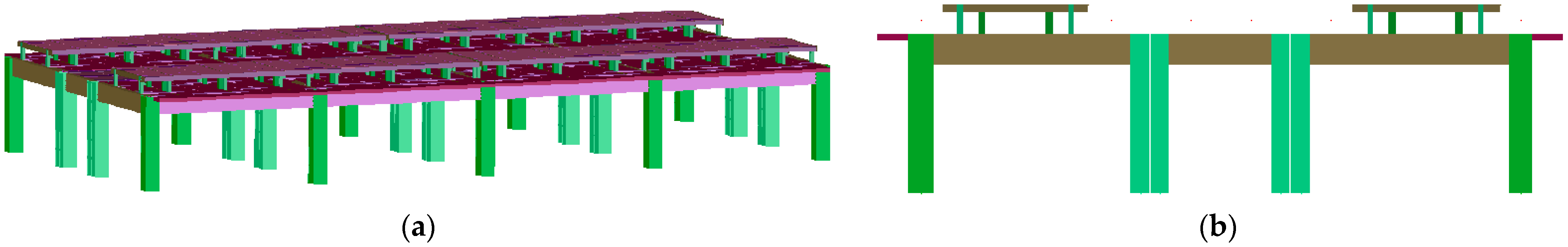
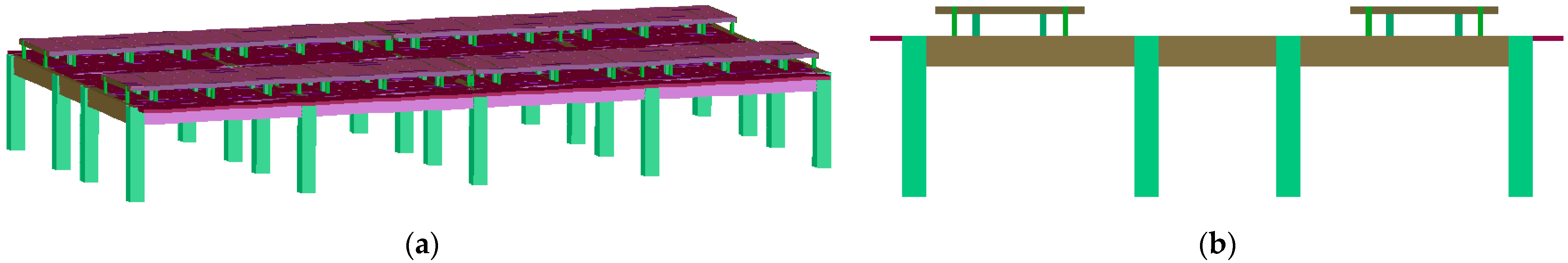
3.2. Finite Element Models of Track-Station System
3.3. Establishment and Solution of the Coupled Vibration Equations for the Train-Track-Station System
- (1)
- The total potential energy of the spatial vibration of the vehicle-track-station system is obtained by calculating and summing the spatial vibration potential energies of the track-station and the train at a certain moment. The calculation formula is shown in Equation (6):
- (2)
- By applying the principle of constant total potential energy of elastic system dynamics, the variation of the total potential energy is set to zero, as shown in Equation (7):
- (3)
- The track irregularity is regarded as a self-excitation source. Based on the total potential energy variation equation and using the “position-matching” rule for forming matrices, the mass matrix , damping matrix , stiffness matrix , and load vector of the system at any time t are calculated. The vibration equation of the coupled vehicle-track-station system is established, as shown in Equation (8):
4. Analysis of Dynamic Responses of Station Structures Under Various Working Conditions and Calculation Results of Dynamic Characteristics of the Model
4.1. Dynamic Characteristic Analysis of Station Structures
4.2. Dynamic Response Results and Analysis of the Station Under Various Working Conditions
5. The Impact of Mainline Structural Joint on the Dynamic Response of Station Structures
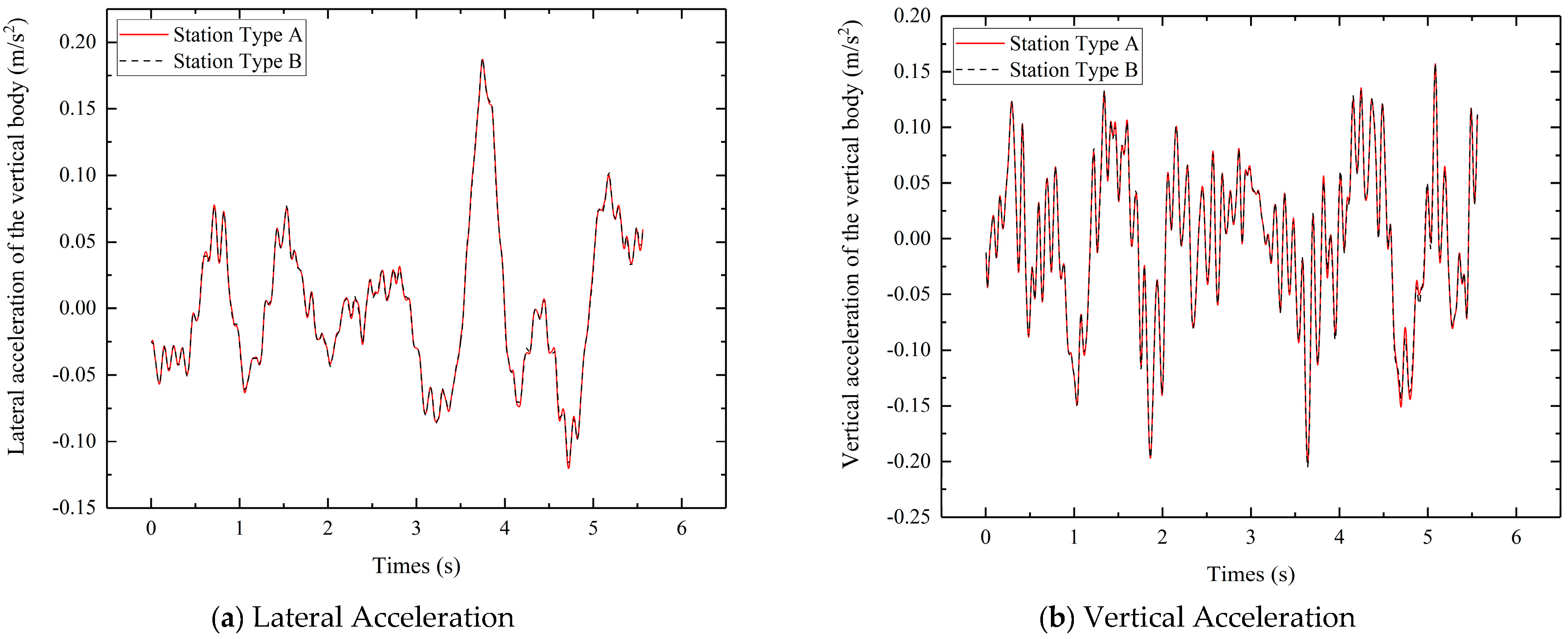
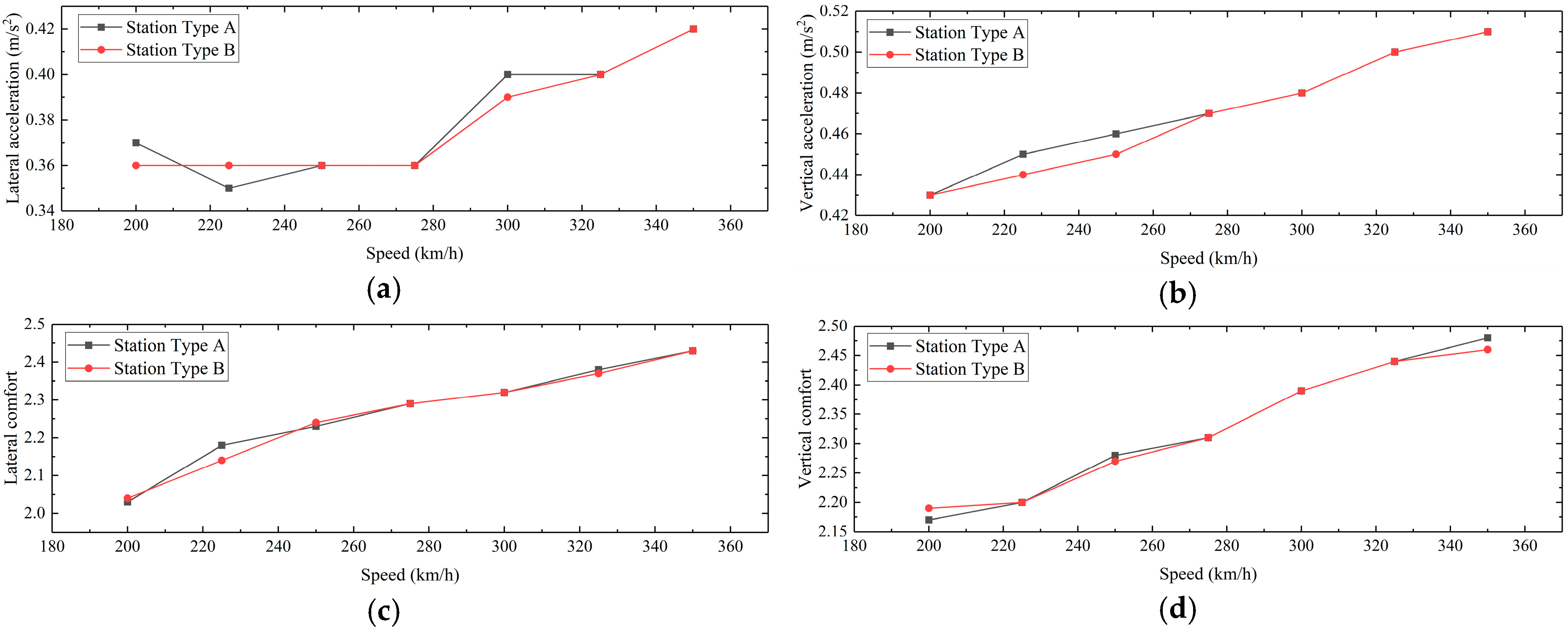
5.1. Comparison and Analysis of Train Response
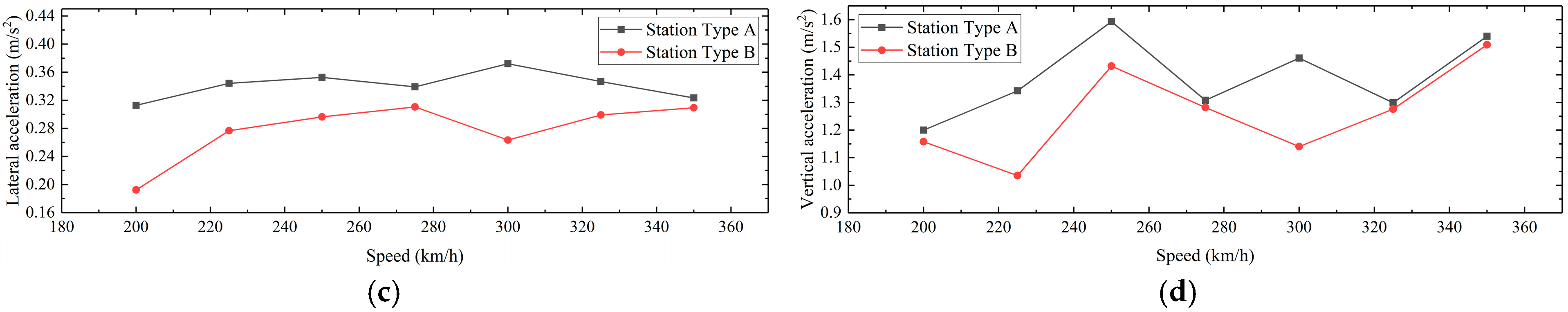
5.2. Comparison and Analysis of the Rail Bearing Floor Slab Response
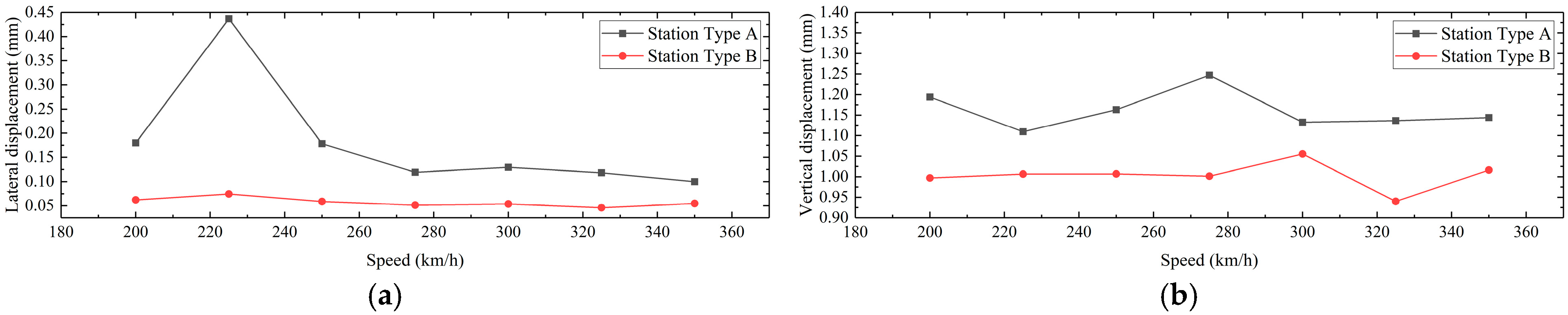
5.3. Comparison and Analysis of the Platform Slab Response
6. Conclusions
- (1)
- When trains pass through the station structure at speeds of 200~350 km/h on the mainline and 80 km/h on the arrival-departure lines, the lateral and vertical accelerations of the rail bearing floor slab, for both the arrival/departure line “building-bridge integrated” and the mainline “building-bridge integrated” structures, remain within the permissible limits. Additionally, the lateral and vertical accelerations of the train, derailment coefficient, and wheel load reduction rate all satisfy the regulatory requirements. The comfort indices of the train comply with the current standards, indicating that both structures exhibit satisfactory dynamic performance.
- (2)
- When trains pass through the station structure, the presence or absence of a mainline structural joint has a minimal impact on the dynamic response of trains for the “building-bridge integrated” station structure. For both the arrival-departure line “building-bridge integrated” and the mainline “building-bridge integrated” structures, the lateral and vertical accelerations of the train generally increase with speed. Under the same working conditions, the acceleration time-history curves of the trains with the two different structural configurations are essentially consistent.
- (3)
- The discontinuity in the mainline structure reduces the overall stiffness of the rail bearing floor slab and isolates the train-induced responses transmitted to the platform slab during high-speed operation on the mainline. Therefore, under train loading, the arrival and departure track “building-bridge-integrated” structure with a mainline discontinuity exhibits smaller acceleration responses in the platform slab compared to the mainline “building-bridge integrated” structure without a discontinuity. However, the rail bearing floor slab in the structure with a discontinuity shows larger acceleration and displacement responses. Additionally, the implementation of structural joints often leads to issues such as water leakage and seepage. Thus, for such station structures, it may be considered not to set mainline structural joints.
Author Contributions
Funding
Institutional Review Board Statement
Informed Consent Statement
Data Availability Statement
Conflicts of Interest
References
- Li, S.T. Research for Space Pattern in Area of High-Speed Railway Station. Ph.D. Thesis, Tianjin University, Tianjin, China, 2010. [Google Scholar]
- Chen, C.L.; Wei, B. High-speed rail and urban transformation in China: The case of Hangzhou East Rail Station. Built Environ. 2013, 39, 385–398. [Google Scholar] [CrossRef]
- Shan, J.; Wu, Y.; Yang, X. Three-dimensional stability of two-step slope with crack considering temperature effect on unsaturated soil. J. Cent. South Univ. 2025, 32, 1–19. [Google Scholar] [CrossRef]
- Feldmann, M.; Heinemeyer, C.; Kühn, B.; Sedlacek, G. Prediction of the dynamic behavior of bridges and roof of the railway main station Berlin. ZEV Rail Glas. Ann. 2006, 130, 314–326. [Google Scholar]
- Deng, Z.M. Structural Vibration Analysis and Vibration Control Study on The New Changsha Railway Station. Ph.D. Thesis, Central South University, Changsha, China, 2010. [Google Scholar]
- Zhu, Z.; Davidson, M.T.; Harik, I.E.; Yu, Z. Train-induced vibration characteristics of an integrated high-speed railway station. J. Perform. Constr. Facil. 2017, 31, 04017010. [Google Scholar] [CrossRef]
- He, S.S. Research on Vehicle-Induced Vibration Response of High-Speed Railway Passenger Station. Master’s Thesis, Beijing Jiaotong University, Beijing, China, 2015. [Google Scholar]
- Fang, L.M.; Zhu, Z.H.; Wang, L.D.; Yu, Z. Analysis of train induced random vibration of high-speed railway station with integral station-bridge structure. J. China Railw. Soc. 2017, 39, 117–125. [Google Scholar]
- Fedorova, M.; Sivaselvan, M.V. An algorithm for dynamic vehicle-track-structure interaction analysis for high-speed trains. Eng. Struct. 2017, 148, 857–877. [Google Scholar] [CrossRef]
- Kim, M.; Choi, S. Vibration control of a railroad station using a multiple tuned mass damper technique. J. Korean Soc. Hazard Mitig. 2019, 20, 37–43. [Google Scholar] [CrossRef]
- Yoo, Y.; Kwon, S.J.; Choi, S. Development of vibration mitigation method for a railway station using a tunedmass-dampered platform. J. Korean Soc. Hazard Mitig. 2016, 16, 77–82. [Google Scholar] [CrossRef]
- Zhang, X.; Ruan, L.; Zhao, Y.; Zhou, X.; Li, X. A frequency domain model for analysing vibrations in large-scale integrated building–bridge structures induced by running trains. Proc. Inst. Mech. Eng. Part F J. Rail Rapid Transit 2020, 234, 226–241. [Google Scholar] [CrossRef]
- Ran, W.; Li, Z.; Li, X.; Yi, B.; Zhang, X. Frequency-domain analysis method for vibration responses of a high-speed railway station structure under train load excitation. Vib. Shock 2018, 37, 218–224. [Google Scholar]
- Guo, X.; Wang, S. Research on the Dynamic Response of the Multi-Line Elevated Station with “Integral Station-Bridge System”. Buildings 2024, 14, 758. [Google Scholar] [CrossRef]
- Zhang, J.; Zhang, L.N.; Zhi, G.L.; Hu, W.L.; Guo, T.; Wang, S.L. Study on vehicle-induced vibration characteristics of high-speed railway bridge station structure. Earthq. Eng. Eng. Vib. 2023, 43, 222–231. [Google Scholar]
- Xu, W. Analysis of Vehicle-Induced Dynamic Effect of Long-Span Station Structure with Station-Bridge Integration. Master’s Thesis, Wuhan University of Technology, Wuhan, China, 2010. [Google Scholar]
- Xie, W.P.; Yang, Y.Z.; Li, W. Research on vibration and structural noise measurement of subway elevated station combi-nation of bridge and construction. J. Railw. Sci. Eng. 2021, 18, 1837–1845. [Google Scholar]
- Yang, N.; Guo, T.; Sun, G. Train-induced vibration on elevated railway station. J. Cent. South Univ. 2013, 20, 3745–3753. [Google Scholar] [CrossRef]
- Guo, T.; Zhi, G.; Zhu, R.; Zhang, L. Train-Induced Vibration Characteristics of a Double-Story High-Speed Railway Station. J. Perform. Constr. Facil. 2024, 38, 04024008. [Google Scholar] [CrossRef]
- Ba, Z.; Jiao, P.; Liang, J.; Liu, G.; Gao, Y. Actual measurement and analysis of station vibration induced by high-speed train. J. Tianjin Univ. 2020, 53, 1211–1217. [Google Scholar]
- TB 10100-2018; Code for Design of Railway Passenger Station. China Railway Publishing House: Beijing, China, 2018.
- Zeng, Q.Y.; Guo, X.R. Theory and Application of Vibration Analysis of Time-Varying Systems on Train Bridges; China Railway Publishing House: Beijing, China, 1999. [Google Scholar]
- Zeng, Q. The principle of total potential energy with stationary value in elastic system dynamics. J. Huazhong Univ. Sci. Technol. 2000, 28, 1–3+14. [Google Scholar]
- Zeng, Q.Y.; Yan, G.P. The “set-in-right-position” rule forming structural method for space analysis of truss bridges. J. China Railw. Soc. 1986, 8, 48–59. [Google Scholar]
- Guo, X.; Liu, J.; Wu, Y.; Jiang, Y. Research on the influencing parameters of the dynamic responses of the elevated station with “integral station-bridge system”. J. Railw. Sci. Eng. 2023, 20, 671–681. [Google Scholar]
- TB 10002-2017; Code for Design on Railway Bridge and Culvert. China Railway Publishing House: Beijing, China, 2017.


| Comparison Program | Arrival-Departure Line “Building-Bridge Integrated” Structure | Mainline “Building-Bridge Integrated” Structure | Building-Bridge Separating Structure |
|---|---|---|---|
| Arrival-Departure Line Train Load Transfer Relationship | The train load on the arrival-departure line is applied to the rail bearing floor slab, distributed through the longitudinal and transverse beam system, and then transmitted to the platform slab and the ground through the connecting columns. | The train load on the arrival-departure line is applied to the rail bearing floor slab, distributed through the longitudinal and transverse beam system, and then transmitted to the platform slab and the ground through the connecting columns. | The train load acts on the bridge structure. |
| Mainline Train Load Transfer Relationship | The mainline train load is directly transferred to the ground through the track beam and bottom frame columns. | ||
| Structural characteristics | The structure has good structural integrity. The rail bearing floor slab of the arrival and departure lines is closely connected with the platform level. In contrast, the rail bearing floor slab of the mainline is separated from the platform level by construction joints. | The structure has good structural integrity and seismic performance. The rail bearing floor slab does not have construction joints. | The bridge structure is independent of the architectural structure. |
| Architectural Layout | The dimensions of the beam components are relatively small, resulting in a lower overall height of the station. | The smaller dimensions of the beam components allow for more flexible utilization of the space beneath the bridge, while also contributing to a lower overall height of the station. | The beam components have large dimensions, resulting in a large footprint. Due to the significant height of the box girders, the overall height of the station is increased. |
| Vehicle Structure | Lateral Sway | Heave | Yaw | Pitch | Roll |
|---|---|---|---|---|---|
| Vehicle Body | |||||
| Front Bogie Frame | |||||
| Rear Bogie Frame | |||||
| First Wheelset | / | / | / | ||
| Second Wheelset | / | / | / | ||
| Third Wheelset | / | / | / | ||
| Fourth Wheelset | / | / | / |
| Parameters | Notation |
|---|---|
| Vehicle body mass, bogie mass, wheelset mass | |
| Moment of Inertia of the vehicle body and Bogie | |
| Stiffness of Primary Suspension System | |
| Stiffness of Secondary Suspension System | |
| Damping Coefficient of Primary Suspension System | |
| Damping Coefficient of Secondary Suspension System |
| Cutoff Frequency | / | 0.8246 |
/ | 0.0206 | |
/ | 0.438 | |
| Roughness Coefficient | / | |
/ | ||
/ |
| Station Structure Parameters | Station Type A | Station Type B |
|---|---|---|
| Material Strength of Beams, Columns, and Slabs | C45 | C45 |
| Number of nodes | 1089 | 989 |
| Number of beam elements | 1452 | 1342 |
| Number of shell elements | 768 | 768 |
| Station Structure Type | Order | Mode Frequency/Hz | Natural Period/s | Mode Shape |
|---|---|---|---|---|
| Station Type A | 1 | 1.980 | 0.5051 | First-order lateral bending of the main structure |
| 2 | 1.985 | 0.5038 | Second-order lateral bending of the main structure | |
| 3 | 2.122 | 0.4713 | Third-order lateral bending of the main structure | |
| 4 | 2.227 | 0.4490 | First-order longitudinal drift of the main structure | |
| 5 | 2.234 | 0.4476 | Second-order longitudinal drift of the main structure | |
| 6 | 2.392 | 0.4181 | Fourth-order lateral bending of the main structure | |
| 7 | 2.400 | 0.4167 | Fifth-order lateral bending of the main structure | |
| 8 | 2.557 | 0.3911 | Sixth-order lateral bending of the main structure | |
| 9 | 2.710 | 0.3690 | Third-order longitudinal drift of the main structure | |
| 10 | 5.993 | 0.1669 | First-order vertical bending of the main structure | |
| Station Type B | 1 | 2.162 | 0.4625 | First-order longitudinal drift of the main structure |
| 2 | 2.170 | 0.4608 | First-order lateral bending of the main structure | |
| 3 | 2.531 | 0.3951 | Second-order lateral bending of the main structure | |
| 4 | 6.023 | 0.1660 | First-order vertical bending of the main structure | |
| 5 | 6.169 | 0.1621 | Second-order vertical bending of the main structure | |
| 6 | 6.200 | 0.1613 | Third-order vertical bending of the main structure | |
| 7 | 6.236 | 0.1604 | Fourth-order vertical bending of the main structure | |
| 8 | 6.421 | 0.1557 | Fifth-order vertical bending of the main structure | |
| 9 | 6.479 | 0.1543 | Sixth-order vertical bending of the main structure | |
| 10 | 6.494 | 0.1540 | Seventh-order vertical bending of the main structure |
| Structural Type | Operating Condition | Vehicle Speed (km/h) | Dynamic Coefficient | Displacement (mm) | Acceleration (m/s2) | ||
|---|---|---|---|---|---|---|---|
| Lateral | Vertical | Lateral | Vertical | ||||
| Station Type A | Single Line | 200~350 | 1.17 | 0.271 | 0.880 | 0.352 | 1.533 |
| Double Lines | 200~350 | 1.25 | 0.437 | 1.247 | 0.372 | 1.593 | |
| Triple Lines | 200~350 | 1.25 | 0.437 | 1.247 | 0.372 | 1.593 | |
| Quadruple Lines | 200~350 | 1.25 | 0.437 | 1.247 | 0.372 | 1.593 | |
| Quintuple Lines | 200~350 | 1.25 | 0.437 | 1.247 | 0.372 | 1.593 | |
| Sextuple Lines | 200~350 | 1.25 | 0.437 | 1.247 | 0.372 | 1.593 | |
| Station Type B | Single Line | 200~350 | 1.14 | 0.042 | 0.671 | 0.191 | 1.386 |
| Double Lines | 200~350 | 1.18 | 0.071 | 0.953 | 0.297 | 1.501 | |
| Triple Lines | 200~350 | 1.17 | 0.071 | 1.053 | 0.310 | 1.507 | |
| Quadruple Lines | 200~350 | 1.17 | 0.069 | 1.058 | 0.309 | 1.506 | |
| Quintuple Lines | 200~350 | 1.16 | 0.073 | 1.057 | 0.312 | 1.516 | |
| Sextuple Lines | 200~350 | 1.17 | 0.074 | 1.055 | 0.311 | 1.509 | |
| Structural Type | Operating Condition | Vehicle Speed (km/h) | Displacement (mm) | Acceleration (m/s2) | ||
|---|---|---|---|---|---|---|
| Lateral | Vertical | Lateral | Vertical | |||
| Station Type A | Single Line | 200~350 | 0.000 | 0.000 | 0.000 | 0.000 |
| Double Lines | 200~350 | 0.000 | 0.000 | 0.000 | 0.000 | |
| Triple Lines | 200~350 | 0.119 | 0.424 | 0.064 | 0.734 | |
| Quadruple Lines | 200~350 | 0.119 | 0.424 | 0.064 | 0.740 | |
| Quintuple Lines | 200~350 | 0.129 | 0.478 | 0.073 | 0.740 | |
| Sextuple Lines | 200~350 | 0.129 | 0.480 | 0.075 | 0.629 | |
| Station Type B | Single Line | 200~350 | 0.050 | 0.126 | 0.209 | 0.768 |
| Double Lines | 200~350 | 0.075 | 0.181 | 0.283 | 0.877 | |
| Triple Lines | 200~350 | 0.145 | 0.468 | 0.297 | 1.184 | |
| Quadruple Lines | 200~350 | 0.147 | 0.465 | 0.307 | 1.199 | |
| Quintuple Lines | 200~350 | 0.146 | 0.518 | 0.326 | 1.226 | |
| Sextuple Lines | 200~350 | 0.156 | 0.516 | 0.322 | 1.208 | |
| Structural Type | Operating Condition | Vehicle Speed (km/h) | Power Vehicle | Trailer Vehicle | ||||||||||||
|---|---|---|---|---|---|---|---|---|---|---|---|---|---|---|---|---|
| Derailment Coefficient Q/P | Wheel Load Reduction Rate △P/P | Lateral Force (kN) | Vertical Acceleration (m/s2) | Lateral Acceleration (m/s2) | Sperling Comfort Index | Derailment Coefficient Q/P | Wheel Load Reduction Rate △P/P | Lateral Force (kN) | Vertical Acceleration (m/s2) | Lateral Acceleration (m/s2) Vertical | Sperling Comfort Index | |||||
| Vertical | Lateral | Vertical | Lateral | |||||||||||||
| Station Type A | Single Line | 200~350 | 0.12 | 0.34 | 9.37 | 0.50 | 0.42 | 2.45 | 2.42 | 0.13 | 0.37 | 7.34 | 0.44 | 0.43 | 2.36 | 2.49 |
| Double Lines | 200~350 | 0.12 | 0.34 | 9.65 | 0.51 | 0.42 | 2.46 | 2.42 | 0.14 | 0.37 | 7.39 | 0.45 | 0.43 | 2.36 | 2.49 | |
| Triple Lines | 200~350 | 0.12 | 0.34 | 9.69 | 0.51 | 0.42 | 2.46 | 2.42 | 0.14 | 0.37 | 7.47 | 0.45 | 0.43 | 2.36 | 2.49 | |
| Quadruple Lines | 200~350 | 0.15 | 0.44 | 10.94 | 0.51 | 0.42 | 2.46 | 2.42 | 0.14 | 0.48 | 8.08 | 0.45 | 0.43 | 2.36 | 2.49 | |
| Quintuple Lines | 200~350 | 0.15 | 0.44 | 10.94 | 0.51 | 0.42 | 2.46 | 2.43 | 0.14 | 0.48 | 8.10 | 0.45 | 0.43 | 2.36 | 2.49 | |
| Sextuple Lines | 200~350 | 0.15 | 0.44 | 10.92 | 0.51 | 0.42 | 2.46 | 2.43 | 0.14 | 0.48 | 8.09 | 0.45 | 0.43 | 2.36 | 2.49 | |
| Station Type B | Single Line | 200~350 | 0.12 | 0.34 | 9.37 | 0.50 | 0.42 | 2.45 | 2.42 | 0.13 | 0.37 | 7.34 | 0.44 | 0.43 | 2.36 | 2.49 |
| Double Lines | 200~350 | 0.12 | 0.34 | 9.65 | 0.51 | 0.42 | 2.46 | 2.42 | 0.14 | 0.37 | 7.39 | 0.45 | 0.43 | 2.36 | 2.49 | |
| Triple Lines | 200~350 | 0.12 | 0.34 | 9.69 | 0.51 | 0.42 | 2.46 | 2.42 | 0.14 | 0.37 | 7.47 | 0.45 | 0.43 | 2.36 | 2.49 | |
| Quadruple Lines | 200~350 | 0.15 | 0.44 | 10.94 | 0.51 | 0.42 | 2.46 | 2.42 | 0.14 | 0.48 | 8.08 | 0.45 | 0.43 | 2.36 | 2.49 | |
| Quintuple Lines | 200~350 | 0.15 | 0.44 | 10.94 | 0.51 | 0.42 | 2.46 | 2.43 | 0.14 | 0.48 | 8.10 | 0.45 | 0.43 | 2.36 | 2.49 | |
| Sextuple Lines | 200~350 | 0.15 | 0.44 | 10.92 | 0.51 | 0.42 | 2.46 | 2.43 | 0.14 | 0.48 | 8.09 | 0.45 | 0.43 | 2.36 | 2.49 | |
Disclaimer/Publisher’s Note: The statements, opinions and data contained in all publications are solely those of the individual author(s) and contributor(s) and not of MDPI and/or the editor(s). MDPI and/or the editor(s) disclaim responsibility for any injury to people or property resulting from any ideas, methods, instructions or products referred to in the content. |
© 2025 by the authors. Licensee MDPI, Basel, Switzerland. This article is an open access article distributed under the terms and conditions of the Creative Commons Attribution (CC BY) license (https://creativecommons.org/licenses/by/4.0/).
Share and Cite
Guo, X.; Liu, Y.; Liu, J. Research on the Dynamic Behavior of “Building-Bridge Integrated” Railway Bridge-Type Station with Setting the Structural Joints on the Mainline. Appl. Sci. 2025, 15, 4335. https://doi.org/10.3390/app15084335
Guo X, Liu Y, Liu J. Research on the Dynamic Behavior of “Building-Bridge Integrated” Railway Bridge-Type Station with Setting the Structural Joints on the Mainline. Applied Sciences. 2025; 15(8):4335. https://doi.org/10.3390/app15084335
Chicago/Turabian StyleGuo, Xiangrong, Yaolin Liu, and Jianghao Liu. 2025. "Research on the Dynamic Behavior of “Building-Bridge Integrated” Railway Bridge-Type Station with Setting the Structural Joints on the Mainline" Applied Sciences 15, no. 8: 4335. https://doi.org/10.3390/app15084335
APA StyleGuo, X., Liu, Y., & Liu, J. (2025). Research on the Dynamic Behavior of “Building-Bridge Integrated” Railway Bridge-Type Station with Setting the Structural Joints on the Mainline. Applied Sciences, 15(8), 4335. https://doi.org/10.3390/app15084335