Article

A Prototype Mechatronic Device for Upper Limb Rehabilitation and Analysis of Its Functionality

1
Department of Applied Mechanics and Robotics, The Faculty of Mechanical Engineering and Aeronautics, Rzeszów University of Technology, Al. Powstańców Warszawy 8, 35-959 Rzeszów, Poland
2
Department of Mechanical Engineering, The Faculty of Mechanical Engineering and Aeronautics, Rzeszów University of Technology, Al. Powstańców Warszawy 8, 35-959 Rzeszów, Poland
*
Author to whom correspondence should be addressed.
Appl. Sci. 2025, 15(12), 6613; https://doi.org/10.3390/app15126613
Submission received: 23 March 2025 / Revised: 2 June 2025 / Accepted: 6 June 2025 / Published: 12 June 2025

Abstract

A prototype device was developed as a simple yet effective tool for the rehabilitation of individuals with upper limb paresis resulting from stroke. The primary objective of the design process was to create a portable rehabilitation device that could be remotely controlled by a therapist via a Bluetooth protocol. The device enables the execution of upper limb rehabilitation exercises and integrates essential modules for assessment, reporting, and user feedback (biofeedback). It comprises a base and three movable arms, each fitted with a container at its distal end. The central arm, positioned at the midpoint of the device’s housing, holds a storage container from which specific objects are retrieved by the user. This arm features an adjustable reach. The remaining two arms are equipped with task-specific containers mounted at their ends. The conceptual framework is based on the execution of various tasks displayed on a screen. The user retrieves objects from the central storage unit and places them into either the left or right container, as indicated. The target container is highlighted both visually on the screen and via an illuminated LED indicator. Pre-programmed sequences for object retrieval and placement are presented on the display, offering clear guidance for the correct positioning and ordering of blocks within the designated containers. The device includes 12 dedicated blocks varying in shape, colour, material, and texture. A mechatronic control system governs the container positioning and arm inclination, enabling a precise adjustment of range of movement according to the exercise’s requirements. A dedicated software system has also been developed for control and management. Functional testing of the prototype was conducted to assess the device’s effectiveness and practical applicability in rehabilitation settings.

1. Introduction

Stroke is among the leading causes of mortality worldwide and simultaneously one of the primary contributors to long-term disability, ranking second or third depending on the data source [1]. It is estimated that one in four individuals will experience a stroke during their lifetime [2]. In Europe, over 2.5 million new stroke cases are recorded annually. More than 400,000 people live with permanent consequences, and over 33 million stroke survivors require rehabilitation [3,4]. In highly developed countries, between 31% and 50% of stroke survivors do not regain independence due to extensive brain tissue damage [5,6]. This high proportion is also linked to the lack of adequate diagnostic and rehabilitative methods [7]. Furthermore, 17% to 25% of stroke survivors require continuous care from third parties [8,9,10,11,12,13].
The scale of this issue, coupled with increasing demand for innovative mechatronic solutions in stroke rehabilitation, is well-documented. Projections suggest that in the next 20 to 30 years, the number of people affected by stroke will double. The majority will require medical treatment or rehabilitation for impairments such as speech disorders, memory deficits, or mobility limitations [3,14,15,16,17].
Although stroke is traditionally associated with older adults over the age of 65, its incidence is increasingly observed in younger populations [7]. The World Health Organization (WHO) defines stroke as a sudden focal neurological dysfunction lasting more than 24 h, excluding causes unrelated to cerebral circulation [18]. Stroke, traumatic brain injury, and other neurological conditions are the most common causes of upper limb motor dysfunction. Common symptoms of stroke include [3,17,19,20]
Paresis or complete paralysis;
Altered muscle tone (either increased or decreased);
Speech disorders or loss of speech;
Orofacial paralysis (e.g., swallowing and feeding difficulties);
Psychological issues such as emotional instability, depression, and personality changes;
Spasticity (exaggerated stretch reflex response).
As a result of these impairments, abnormal postural patterns and atypical movement mechanics frequently develop [21]. Pronounced temporal and spatial asymmetries between limbs are observed in approximately 48% to 82% and 44% to 62% of post-stroke individuals, respectively [22,23,24]. Jamal et al. [25] suggest that spatial body perception disturbances partly account for these postural asymmetries.
Rehabilitation following stroke primarily focuses on motor recovery techniques [26], enabling multidirectional stimulation and function-oriented improvement. Motor rehabilitation is defined as a process engaging stroke survivors in activities aimed at improving motor functions, capabilities, and daily performance [27]. Rehabilitative exercises play a critical role in this recovery process [28,29,30,31]. However, the shortage of therapists and caregivers supporting individuals with physical disabilities is expected to worsen in the coming years, posing a significant challenge [16,17,32]. Robotic devices have demonstrated potential in addressing this gap, as noted in recent studies [33], though their availability in both clinical and home environments remains limited—highlighting the need for further development.

2. Motivation and Contribution

The design of rehabilitation devices necessitates a thorough anatomical analysis of the targeted body segment, along with an assessment of motor capabilities in patients with specific impairments, such as limb paresis [32,34,35,36,37,38,39,40,41,42,43,44,45,46,47,48,49,50,51,52,53,54,55,56]. Typically, a prototype is developed to verify the underlying design assumptions. During the design process—which extends into the construction phase—the development of both conceptual and prototype solutions is essential.
A significant proportion of existing devices incorporate highly complex mechatronic systems [32,34,35,36,37,38,39,40,41,42,43,44,45,46,47,48,49,50,51,52,53,54,55,56]. They are intended for function-specific evaluation, depending on the area of impairment, as well as for the ongoing monitoring of selected motor functions throughout the rehabilitation process [56,57,58,59,60]. Consequently, their high cost constitutes a primary barrier to widespread adoption. A review of current solutions reveals a lack of simple mechatronic devices on the market based on the Box and Block Test methodology, which could support active rehabilitation exercises [61,62,63,64,65,66,67,68,69,70,71].
A portable upper limb rehabilitation device is described in an American patent publication [61]. This device features a forearm support mounted on a movable base, enabling the monitoring of both limb movement and forearm pressure exerted on the support surface. The forearm attachment facilitates guided motion during exercises, thereby preventing uncontrolled and improper limb movements.
Another relevant system within the scope of this study is the Bimeo PRO, designed specifically for upper limb rehabilitation, with a focus on enhancing hand motor function [62]. The system comprises a split spherical structure and two electronic measurement modules, which are affixed via straps to the wrist and elbow, along with a base on which the entire sphere or its halves may be mounted. Rehabilitation exercises are modelled on daily hand activities, with task instructions presented on a monitor to guide the process.
A further mechatronic rehabilitation device for individuals with hand dysfunction is the Pablo system [63]. It includes a universal mechatronic shaft and a set of passive auxiliary external components into which the shaft can be inserted. This shaft is used for assessing and training finger and arm movements, measuring grip strength and range of motion, and providing audiovisual feedback via a monitor. An additional passive module combined with the shaft enables wrist and elbow training through exercises performed using a ball that supports the open hand.
Tyromotion Myro [64] is another notable rehabilitation device for upper limb therapy, especially hand rehabilitation. It incorporates a touchscreen panel that enables virtual reality-based exercises. The adjustable screen allows task-based rehabilitation involving real objects—such as a pen—thereby enhancing user engagement. A similar approach is employed in a device developed at the University of Alberta, known as The Air Touch System [65]. This system enables users to complete rehabilitation tasks displayed on a touchscreen integrated into a tabletop. Exercises are performed by moving fingers across the display, creating an intuitive and interactive training environment.
In the context of upper limb rehabilitation and assessment—particularly of hand function—virtual reality (VR) systems based on the Box and Block Test (BBT) and the Fugl-Meyer Assessment scale (FMA) have also been investigated. Several studies have examined the effectiveness of simplified rehabilitation devices such as Neuro-X® [66]. These systems rely on videographic communication and require participants to perform specific tasks, such as maintaining the balance of a virtual object on screen, responding exclusively with hand movements.
Similarly, Kim et al. [67] employed a robotic arm from the Neuro-X® system in a study involving BBT tasks. During testing, the impaired limb remained in a fixed position relative to the participant’s body. Contemporary rehabilitation strategies increasingly incorporate VR technology [68], which has the potential to improve patients’ ability to manage complex scenarios. Adaptive VR-based training may be further enhanced by integrating real-time kinematic and kinetic data, physiological measurements, and offline analytical tools that allow the adaptive control of simulated elements [69].
Vosinakis et al. [70] presented a rehabilitation study in which participants observed a virtual representation of their limb on a screen. The task involved moving virtual blocks between boxes using hand movements, simulating the Box and Block Test (BBT). A notable limitation of this method is the absence of physical resistance—participants do not engage all upper limb muscles, particularly those in the hand, nor do they experience any haptic feedback or reaction force.
Another device based on the BBT was described in [71], where the authors evaluated its effectiveness in rehabilitation across three age groups. In this system, participants manipulated a gripper linked to a mechanical lever within a mechatronic setup, transferring virtual objects from one box to another while bypassing an obstacle. However, a key limitation of this approach is the uniformity of the grip mechanism—participants consistently employed the same grasp pattern in relation to the lever and the finger sensor mechanism.
Several studies [72,73,74,75,76] address modifications and improvements to virtual systems for performing BBT-based exercises. However, in the absence of haptic rendering, grasping motions in virtual environments differ significantly from natural physical interactions [77]. Another BBT-related development employed proximity sensors and a cube-counting system integrated with a mobile application [78].

3. Concept and Design Solution for the Rehabilitation Device

3.1. Functional Assumptions of the Device

During the design process, contextual factors were identified based on criteria outlined in [79]. These factors are critical and influence the structure of rehabilitation technologies [80]. The needs and specifications for a potential home-based rehabilitation device that supports independent arm exercises have been summarised in several studies [81,82,83]. The key functional assumptions of the proposed device are as follows [84]:
  • The rehabilitation device must not require the installation of sensors or mechatronic components directly on the user’s limb.
  • The solution should enable users to physically perceive the shape and texture of the manipulated objects and support the diagnosis of insufficient grip strength based on surface properties, shape, or weight. Additionally, colour coding may assist in object identification and ensure correct placement.
  • The system should promote natural limb movement using real objects of varying shapes and weights. A mechatronic mechanism should facilitate the adjustable positioning of the arms and containers, thereby extending the range of motion and enhancing the rehabilitation process.
  • The mechatronic system and accompanying software should incorporate diagnostic functionalities, including assessments of task completion time, object shape and weight, and the number of repetitions in cases of an incomplete or impaired task performance.
  • The device should have a universal and adaptable design, allowing for adjustment to different limb lengths and configurations. It should be portable and suitable for use on tabletops or desks.

3.2. Concept

The primary objective of the project was to develop a mechatronic device for upper limb rehabilitation that enables the user—typically a patient—to perform dedicated tasks displayed on a screen. These tasks involve repositioning objects (blocks) into designated containers.
A conceptual diagram of the rehabilitation device is shown in Figure 1. The device is primarily intended for individuals requiring intensive, active upper limb exercises, which may involve both arms simultaneously or each arm individually, depending on the rehabilitation therapist’s recommendation. The design prioritises repetitive movement across the entire upper limb, including the wrist and fingers.
The rehabilitation device consists of a base (Figure 1b) on which three drive modules are mounted in a linear configuration. These drive modules are positioned to face the user. Each drive module is connected to an arm: two lateral arms (left and right; see Figure 1a) constitute the task modules, while the central arm comprises the storage module. An electric motor is mounted at the end of the central arm, with a storage container affixed to its shaft. This container is open at the top and features primary vertical walls, along with removable secondary walls.
The central arm is mounted lower than the side arms to avoid any interference during movement. It consists of two telescopically connected profiles with adjustable locking holes, allowing the arm length to be customised and secured. Similarly, each task arm is equipped with an electric motor at its end, which drives a rotating task container mounted on the motor shaft. Each task container features a plate with rounded edges and three smaller containers mounted on its upper surface (these may be designed as separate containers set into recesses on the plate).
In the initial setup, two of the three containers in each task module are positioned closer to the user, while the third is farthest away, nearer the display. Each container recess is fitted with a pressure sensor that detects when an object has been correctly placed. Additional control buttons will be located between the containers and on the front edge of the plate; these will be used in advanced training stages to allow manual confirmation of the task’s completion.
Each task container will also be equipped with colour sensors located in grooves at the front edge of the base and on the side facing the storage module. These sensors are installed on the inner vertical walls of the containers and are used to detect the colour of the inserted objects. RGB LED indicators are included to signal correct object placement in the designated container sections.
The base plate, which holds the containers, is designed with a curvature radius that is smaller on the side nearest the two containers and larger on the side facing the display. Task containers are fitted with interchangeable covers featuring specific cut-out shapes. These flat covers, mounted individually, include through-holes that allow objects to be inserted into the containers below.
To ensure effective user interaction and ease of operation for staff, the device includes a touchscreen LCD display. Control of and interaction with the device will be facilitated via a graphical user interface. The screen is mounted on an adjustable arm, allowing its position and tilt angle to be modified according to individual user needs. The control module is integrated into the base of the device in a way that does not obstruct the user or medical personnel.

3.3. Prototype Solution of the Device

The application of a mechatronic design approach throughout all stages of the development process enabled a detailed refinement of the proposed structural concept. Following the development of the prototype concept, a systematic design procedure was established to achieve the desired functional and ergonomic characteristics of the device. Based on the defined specifications, a topological shape optimisation process was conducted to determine the optimal structural configuration.
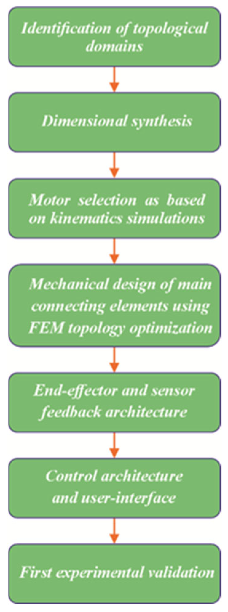
The design process was implemented in a series of sequential stages, as illustrated in Figure 2. During both the design and prototyping phases, particular emphasis was placed on ensuring user comfort and safety, in accordance with the recommendations outlined in [85]. The device is intended for seated use at a table, and all drive mechanisms are fully integrated within the base structure, thereby minimising external protrusions and potential hazards.
During the development of the device’s construction, particular attention was given to ensuring comfort during use for individuals with diverse body types. The key anatomical features of the entire human upper limb were identified. Anthropometric data were collected for the adult population, including women aged 20–60 years and men aged 20–65 years [86,87,88]. Based on measurements for women in the 5th percentile and men in the 95th percentile, the necessary manipulation space for the upper limb was virtually modelled [89].
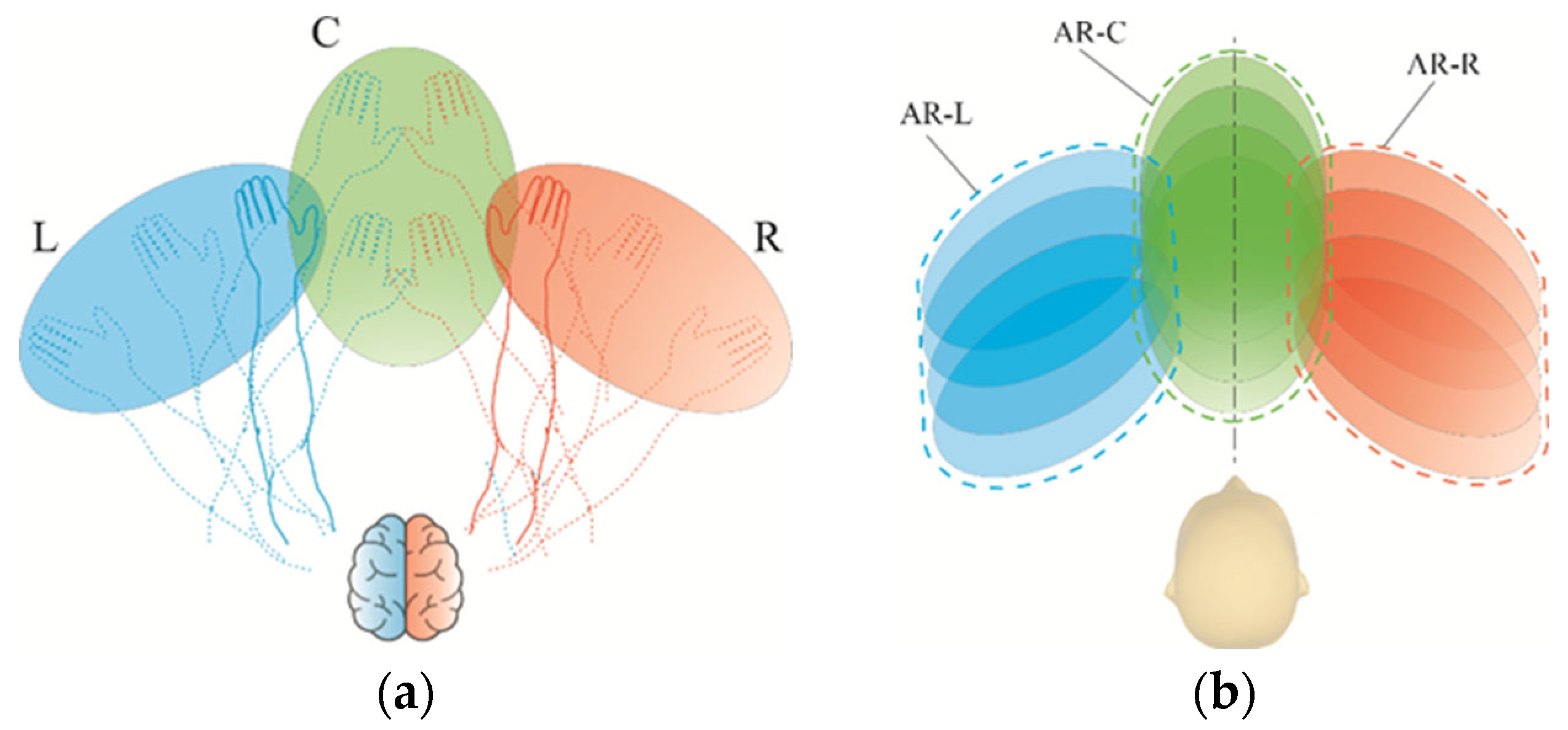
The selection of geometric features, and the corresponding development of the structural design, followed applicable standards [90,91,92]. A topological search was conducted, taking into account the initially assumed working space geometry and dimensionless parameters defined during the conceptual stage (Figure 3). The functional characteristics of the device were developed based on a mapped manipulation area accessible to the human upper limbs [93,94,95]. The lengths and placements of the robotic arms and storage containers were determined through an anatomical analysis of upper limb structures [89].
Based on the established housing dimensions and accessible reach zones for hand movement—specifically for object retrieval (area “1” in Figure 4a)—the parameters lc-h and lc-w were defined. The minimum and maximum lengths of the arms (l1, l2), along with the angular displacement of the external arms, were determined by mapping the potential positions of the storage and task container modules (Figure 4b).
The actual accessible area for inserting objects into the container openings was smaller than the full range of the upper limb manipulation space. To ensure functional and collision-free operation between the storage and container modules, a safe distance (ld, Figure 4b) was established. Once the length of the external arm was defined, its operational range could also be determined. In Figure 4b, coloured dashed lines represent sample hand trajectories—retrieving an object, placing it into a container opening, and pressing a button to confirm task completion.
This process engages the user in grasping the object correctly, transferring it to a specific container (as displayed on the monitor), and performing a button-press motion to indicate the task’s completion. The user maintains a grip on the object while positioning it in the designated slot, followed by extending the fingers to press a control button. This provides additional training for finger extension and whole-arm coordination. To reduce habituation to a fixed button location, alternative control button positions were incorporated into the housing design (see Figure 1).
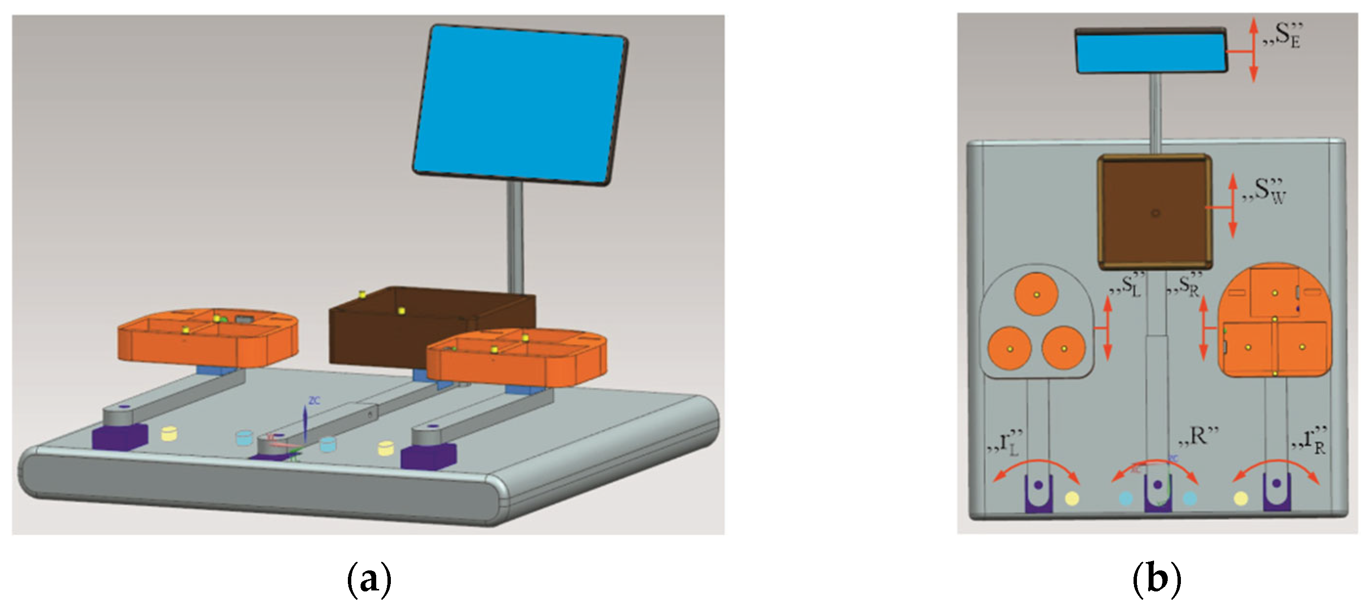
The developed device concept has been granted a patent by the Patent Office of the Republic of Poland under the title “Device for Upper Limb Rehabilitation” [84]. Based on numerical simulations of the working space, a CAD model of the prototype was created (Figure 5). A critical design criterion was achieving a compact overall size to allow for easy transport and convenient placement on a standard table or desk.
Depending on the individual’s capabilities, the shape and dimensions of the exercise objects can be modified. The prototype was designed to accommodate a variety of object shapes, without restricting the form factor. Both lightweight and heavier objects may be used. For the purposes of prototyping and the initial validation, lightweight plastic components were employed.

3.4. Objects Used for Exercises

Interviews with stroke survivors and rehabilitation therapists identified several contextual factors that influence the use of rehabilitation technologies by individuals post-stroke [81,82,83]. Particular emphasis was placed on the person’s hands and their motor ability to grasp objects used during therapeutic exercises [96]. Depending on a patient’s motor capabilities (see Figure 6), suitable objects can be selected for initial rehabilitation sessions. Each phase of the motor response required to grasp various objects engages different levels of hand musculature (Figure 6).
Beyond retrieving an object from the storage module, the patient is also required to place the object into a designated slot within the task container module.
Not every grasping method (Figure 7) facilitates correct object placement. For instance, the grasp shown in Figure 7(d-1) may not allow the object to be aligned horizontally relative to the container. Some post-stroke users may only be capable of generating a palmar-like grasp, involving predominantly the thumb and index finger, with limited use of the remaining digits (Figure 7(d-2,d-3)). Depending on the exercise instruction, these users may attempt to orient the object horizontally (Figure 7(d-2)) or vertically (Figure 7(d-3)) by manipulating the entire upper limb.
Other users may find it easier to grasp spherical objects with elongated protrusions (Figure 7(c-1,c-2)). One of the more basic grasp patterns is the cylindrical grasp, where fingers curl around the object, as illustrated in Figure 6d. This grip requires refined motor control and even finger extension. For cubic objects with slightly elongated dimensions, a cylindrical-type grasp may be mimicked (Figure 7(e-1)), although successful placement into a container slot may necessitate switching to a more suitable grip (Figure 7(e-2,e-3)). This encourages users to consciously adjust their grasping strategy.
In spherical grasps, the hand must be pre-positioned as shown in Figure 6c prior to engagement. While healthy individuals typically execute such movements without difficulty (Figure 7(b-1)), those with motor impairments may achieve only a partial grasping (Figure 7(b-3)). The grip in Figure 7(b-2) enables the lateral placement of a sphere. The pincer grip, which demands precise control and positioning of the fingertips, is particularly useful for manipulating small objects with protruding segments (Figure 7(c-3)). This grasp style enhances the insertion precision and can support task diversity.
The surface texture of spherical objects significantly affects grip retention. For example, foam spheres with a closed-cell structure (Figure 7(a-1)) generate reaction forces upon compression that assist with grasping. To improve tactile control, some spheres feature protrusions adapted to fingertip pad sizes (Figure 7(a-2)) or recessed indentations proportioned for the average finger anatomy (Figure 7(a-3)) [97]. The Box and Block Test (BBT) method supports a high degree of task customisation, enabling the creation of varied and complex exercise sets.
The designed rehabilitation objects include cubes, cuboids, cylinders (including those with rounded edges), and spheres. Their dimensions have been adapted to fit the containers mounted on the device’s arms. Each object can vary in surface texture, which significantly influences the static friction between the skin and the object [98]. It is well established that the object shape affects BBT task performance [99], a conclusion validated across objects of differing weights. Moreover, surface texture alters the dexterity required for manipulation—Slota et al. [100] found that rubber-based elements increased successful grasps by approximately 8% compared to those made of wood or other materials.
All elements used in the preliminary functional testing of the newly developed BBT-based rehabilitation device were fabricated from lightweight, low-density materials. Spherical objects were produced from soft, closed-cell polyurethane foam, while block-type items were made using ABS plastic. Five distinct spherical object variants were developed (Figure 8):
  • No. 1: Smooth and uniform surface;
  • No. 2: Spherical indentations;
  • No. 3: Variable-shaped surface protrusions;
  • No. 4: Spherical protrusions;
  • No. 5: Cylindrical protrusions.
The baseline object was a smooth sphere (No. 1, Figure 8b). Three variants involved the addition of surface features to smaller spheres (Nos. 3 and 4, Figure 8b), while another incorporated spherical indentations of two distinct diameters (No. 2, Figure 8a). The fifth object (No. 5) maintained the base diameter of the smooth sphere but included cylindrical surface protrusions, providing a means of evaluating grip sensitivity. Each object type was colour-coded (dark blue, light blue, yellow, pink, and red) to support task differentiation and the scaling of training difficulty.
The dimensions of indentations and protrusions were selected based on the proportional geometry of human fingers [101]. A geometric overview of selected rehabilitation objects is shown in Table 1.
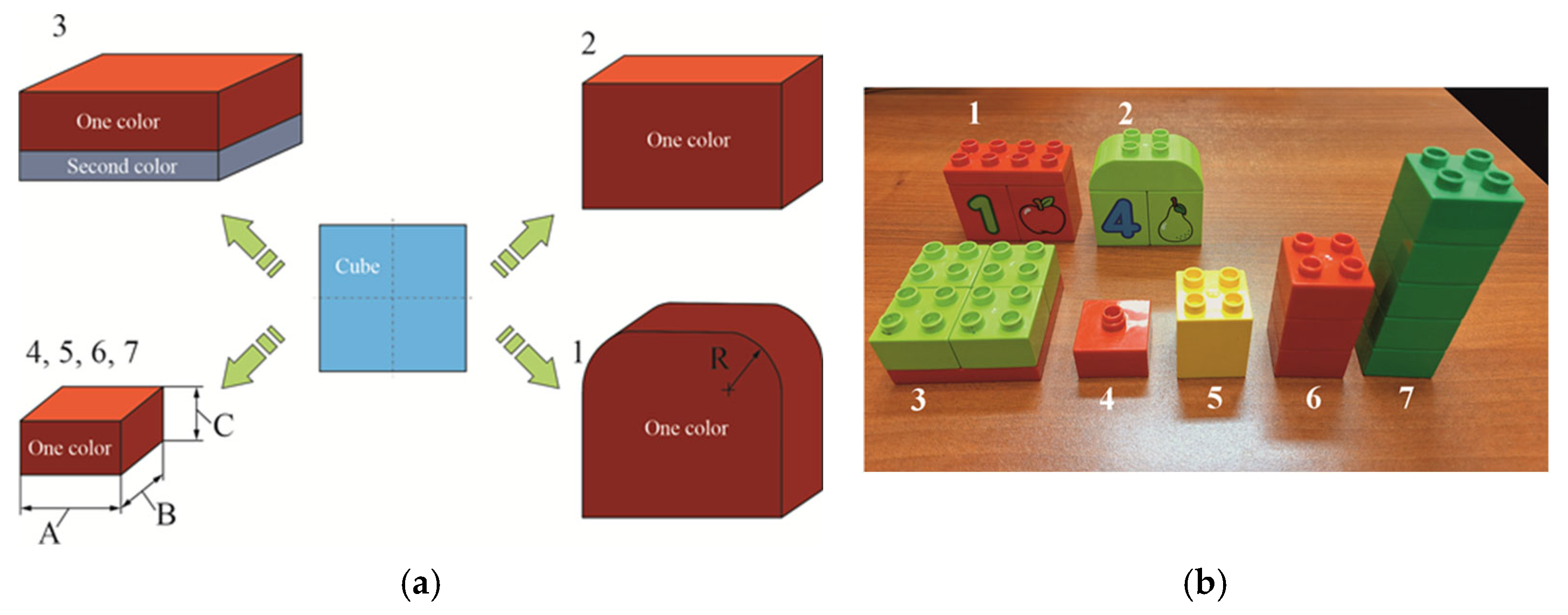
In the prototype, modular cuboid blocks were used, allowing different geometric configurations through interconnection. Objects were manufactured in various colours (e.g., blue, yellow, red, green) and in both single- and two-colour variants (Figure 9a).
For pilot studies, pre-shaped coloured plastic blocks were utilised (Figure 9b, Table 2). However, in the final version, the objects may be fabricated from various materials, including heavier and textured variants. To stimulate tactile receptors and the palmar surface of the hand, certain objects feature regular or irregular surface protrusions, selected according to the individual’s degree of impairment and progress in therapy.
Object No. 3 was designed with two colours—one dominant—facilitating tasks involving orientation recognition and object manipulation. Users are instructed to align the object to match a visual on-screen reference. Where required, users must rotate the object using one hand only, increasing the task’s complexity. Object No. 2 was engineered with two rounded edges to improve orientation within the storage compartment. Objects Nos. 4 through 7 shared identical base dimensions but differed in height, with the tallest fitting into a dedicated storage module.

3.5. Overlays for Geometric Object Identification

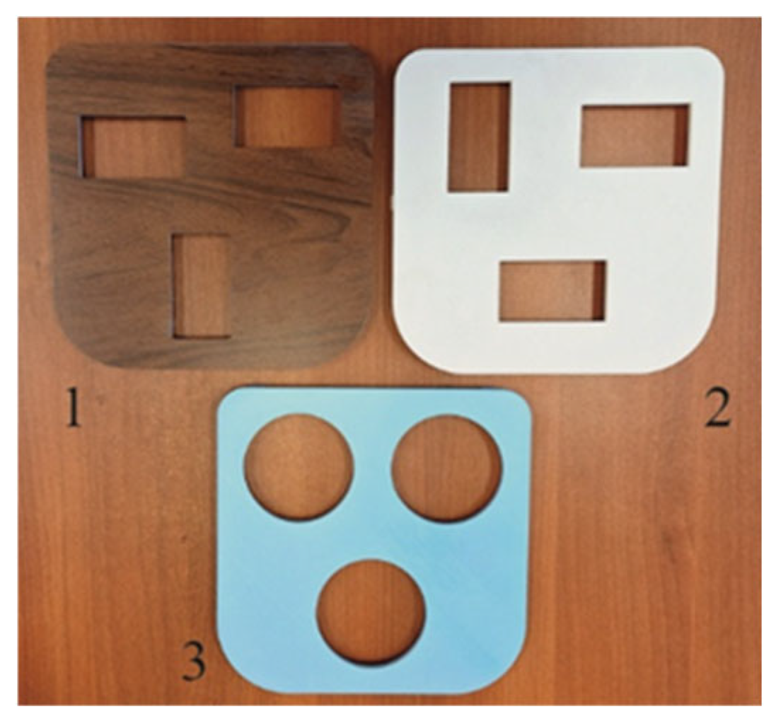
Each overlay is designed with through-holes of distinct shapes, which correspond to the indentations within the task containers. The basic overlay set includes one model with circular openings (Overlay No. 3, Figure 10) and two with rectangular through-holes (Overlays Nos. 1 and 2, Figure 10). Overlay No. 2 is designed with three rectangular slots, positioned differently from those on Overlay No. 1.
A significant advantage of this modular design is the capacity to adjust the difficulty level of rehabilitation tasks. By varying the shape and configuration of the overlay openings and combining them with objects of different shapes, therapists can tailor the task’s complexity to the user’s motor capabilities.
All overlays, along with the final casings for the containers and other components of the upper limb rehabilitation prototype, were fabricated using Fused Filament Fabrication (FFF) technology. A Prusa i3 MK3 3D printer (Prague, Czech Republic) was employed, with polylactic acid (PLA) filament chosen for its ease of printing and minimal constraints.

3.6. Characteristics of the Electronic System

The core of the electronic system integrated into the upper limb rehabilitation prototype is a Raspberry Pi 4B (8 GB RAM) microcomputer (Cambridge, UK), operating in a Linux environment. The microcontroller provides a comprehensive suite of interfaces, including numerous digital I/O ports, a quadrature encoder input, and multiple communication protocols: Ethernet, Wi-Fi, 2× USB 3.0, 2× USB 2.0, microSD, Bluetooth, 2× micro HDMI, a 40-pin GPIO connector, and interfaces for DSI, CSI, SPI, I2C, and UART communication. Key hardware specifications include
  • System-on-Chip: Broadcom 2711;
  • Processor: Quad-core ARM Cortex-A72, 1.5 GHz;
  • Memory: 8 GB LPDDR4 SDRAM;
  • Graphics: Broadcom VideoCore VI.
The Raspberry Pi is enclosed in a protective casing with accessible ports (Figure 11a).
For visual communication with the user and rehabilitation staff, a resistive touchscreen was used—a 10.1-inch IPS LCD (1024 × 600 px) with HDMI and GPIO connections (Waveshare 11870, Figure 11b). This display facilitates the delivery of commands and selection of tasks.
LED indicators are used to provide visual confirmation of an object’s placement within the storage compartments. Micro-switches with straight levers (Type WK315, Figure 12) detect the physical presence of an object in a compartment. These switches operate in a monostable manner, automatically returning to their default position once the lever is released.
To detect an object’s colour, the Adafruit CircuitPython APDS9960 sensor module was implemented (Figure 11c). The presence sensor (labelled “3”) initiates the activation of the colour sensors (“1” and “2”) once an object is detected in the designated compartment. The sensor module is capable of distinguishing red, green, and blue colours based on 16-bit output signals (ranging from 0 to 65,535), where 0 indicates no detection and 65,535 represents maximum intensity.
The APDS9960 module integrates an infrared LED and a control chip with four directional photodiodes, enabling the multi-directional detection of reflected infrared light. It also features built-in UV and IR filters. Initial calibration and validation were conducted using colour-coded test objects, with software used to verify the sensor’s responsiveness and accuracy.
The complete control system comprises the following: infrared beam-break sensors for object detection; I2C multiplexer (TCA9548A, Adafruit, Lakewood, CO, USA) for managing up to eight digital buses; Mini Maestro USB Servo Controller (Las Vegas, NV, USA) (2-channel, Pololu 1356, Figure 11d); Hitec Servo HS645MG modules (San Diego, CA, USA) for actuation.
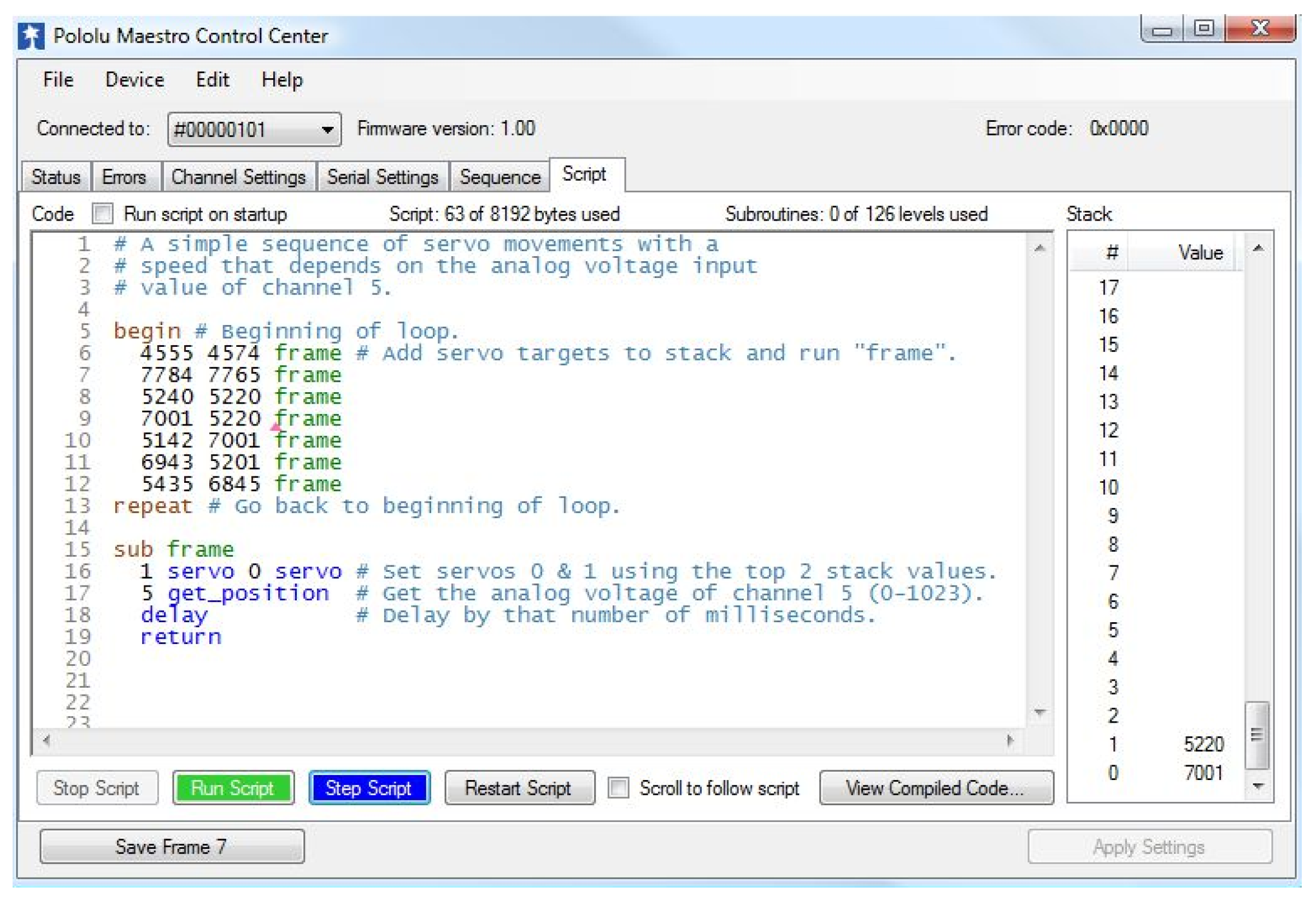
Servo motors are controlled via a PC-based interface using a USB, serial communication, and basic scripting commands. A representative control script interface is shown in Figure 13.
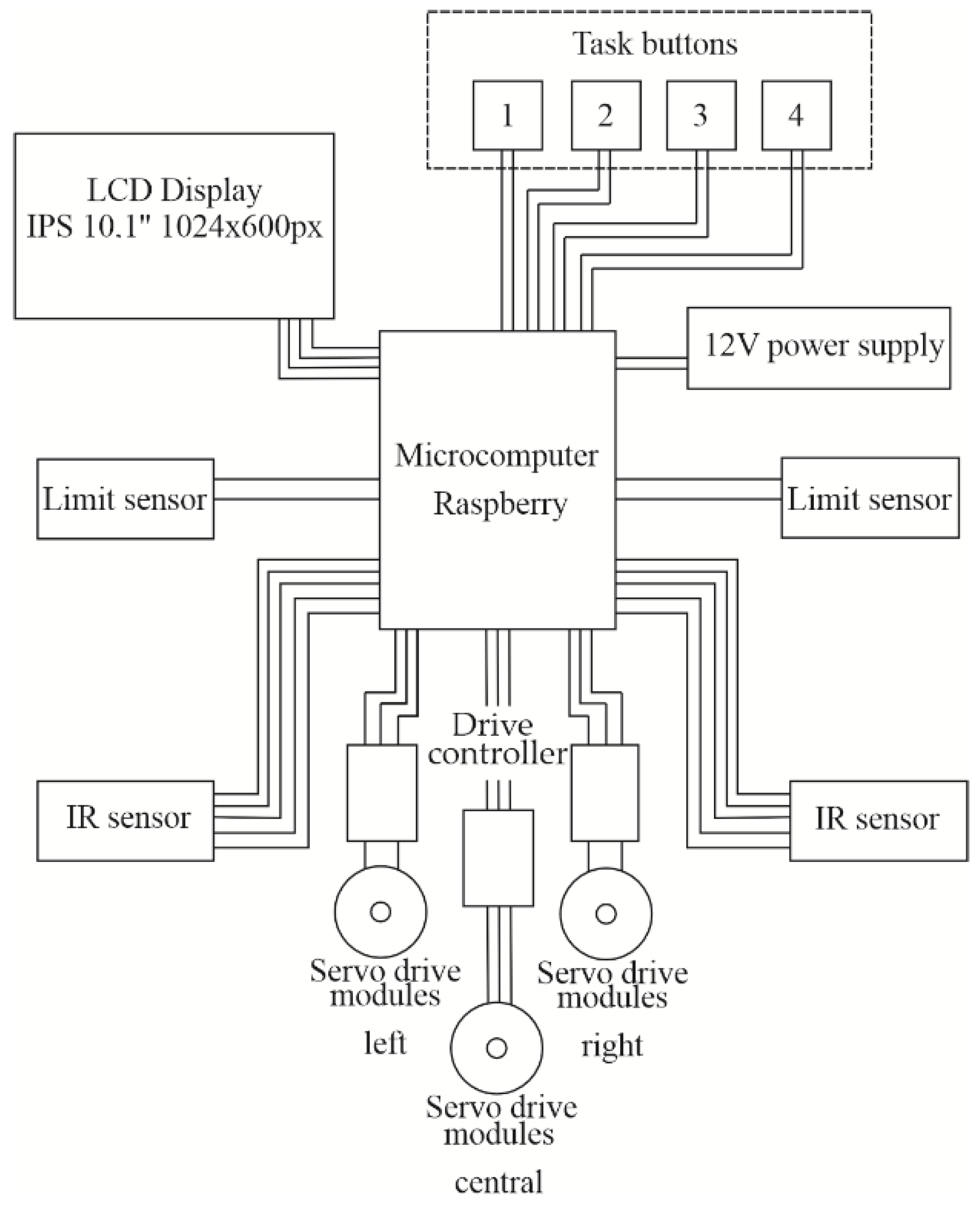
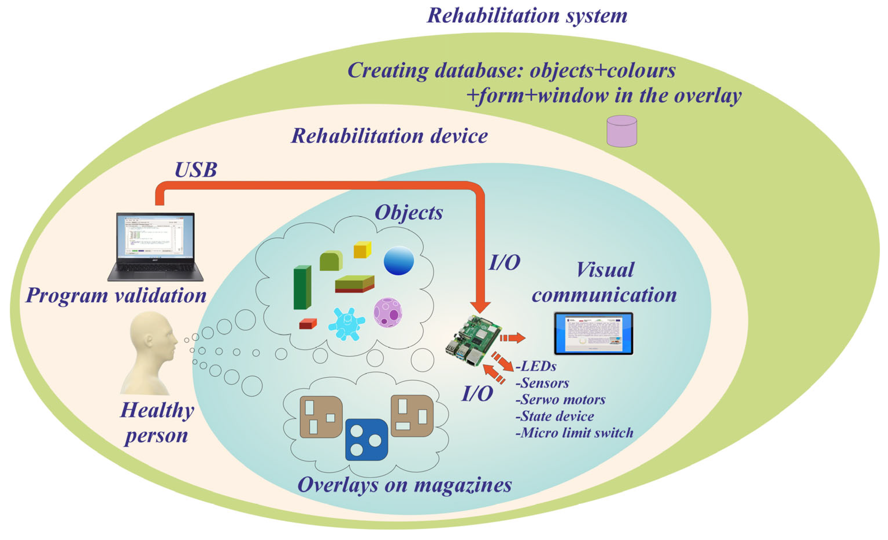
A functional block diagram illustrating the connections between electronic and electromechanical modules is presented in Figure 14. Additionally, buttons (labelled 1–4) were integrated to allow users to indicate the task’s completion manually. Depending on the user’s capabilities, the appropriate button is pressed to confirm the task’s execution.
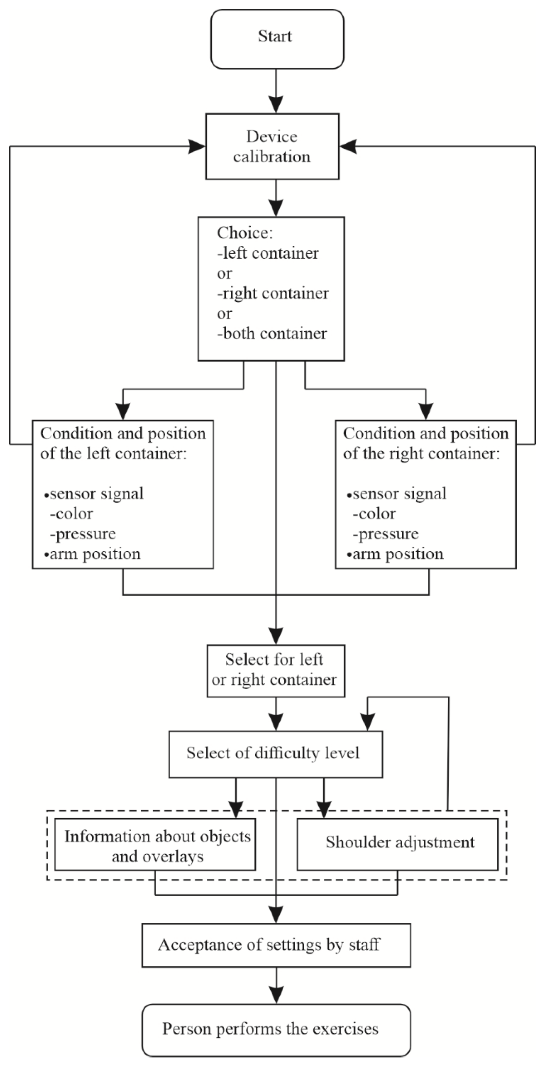
During operation, the touchscreen interface enables calibration, task selection, and interactive control (Figure 15). In calibration mode, users or therapists can specify which limb (left, right, or both) is active, along with the corresponding object containers. The system verifies that compartments are empty and confirms the initial positions of the mechanical arms.
Following this, users can select a task type and difficulty level. Specific training objects, as well as the desired range and length of arm motion, are defined (see Figure 4a). The mechatronic setup is then adjusted to match the user’s functional capabilities. Once confirmed by the supervising operator, the system is ready for therapeutic use.

4. Device Functionality

4.1. Execution of the BBT Task on the Rehabilitation Device

Prior to the commencement of a rehabilitation session, the device undergoes a calibration procedure tailored to the user’s specific functional impairments and the current motor capabilities of the upper limbs. An initial assessment is conducted using dedicated software that allows adjustments in arm inclination and length, thereby determining the optimal range of motion for the exercises.
To assess the appropriate task difficulty level, the task modules are first positioned accordingly. The user is then prompted—via visual and optionally auditory cues—to press designated control buttons. This interaction enables the supervising clinician to make a preliminary evaluation of the patient’s upper limb mobility. Following this, the storage container is loaded with test objects.
The time elapsed between object detection in the designated slot and the button press is recorded. This measurement—along with task accuracy—provides an early indication of the user’s motor function and informs the selection of objects suited to their abilities.
Based on these outcomes, the system proposes specific training routines involving transferring objects from the central module to the peripheral task containers, placing them into the corresponding slots on the overlays. The system is capable of recording and analysing performance data, including completion times, enabling the monitoring of user progress and improvements in movement efficiency over time.
To enable a precise control over tasks’ difficulty, the system incorporates objects of varying colours, dual-colour variants, and diverse geometric shapes. The adjustable position of the mechanical arms further allows therapists to manipulate the movement trajectory, introducing spatial variability into the task. Moreover, the use of objects with different dimensions and surface textures stimulates tactile receptors in the palm and fingers, contributing to enhanced somatosensory feedback.
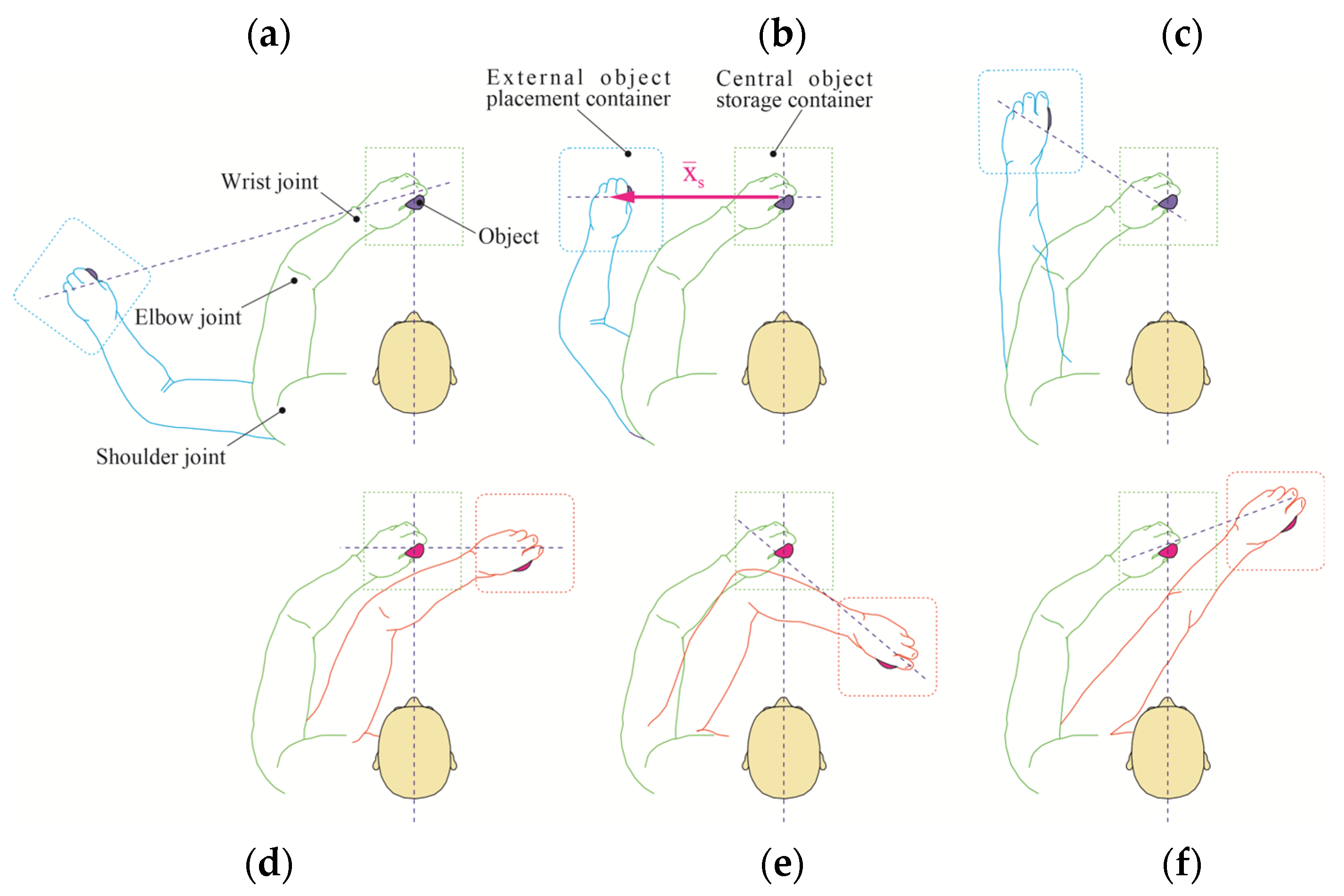
A variety of exercise configurations are supported, with representative scenarios illustrated in Figure 16a–f. Tasks may require a full limb extension, for example
  • Ipsilateral object placement (same side as the active limb; e.g., Figure 16a,c);
  • Contralateral object placement (opposite side of the active limb; e.g., Figure 16b,f);
  • Cross-body manipulations (right limb operating in the left-side field or vice versa);
  • Combinations of manipulation zones and containers.
Each configuration targets specific joint actions and ranges of motion, including shoulder flexion/extension, elbow bending, and wrist articulation (Figure 16). These spatially distinct exercises activate different motor pathways, promoting a comprehensive upper limb rehabilitation.
Additionally, many of the object manipulation tasks are accompanied by a button press (see Figure 5), thereby increasing cognitive–motor integration and introducing an element of dual-task training.
Depending on the programmed task sequence within a given exercise scenario, different degrees of joint motion are engaged.
These motions follow the standards defined by the International Society of Biomechanics (ISB) [102].

4.2. System Setup and Initialisation

The verification of mechanical and software functionality was conducted following a structured sequential operation tree, as illustrated in Figure 17. This structure encompasses all verification stages, including feedback pathways between system components. The final version of the source code—integrating mechanical elements, sensors, and control algorithms—was uploaded to the device’s non-volatile memory to ensure the persistence of operation settings and calibration data.
The completed device required the proper calibration and identification of sensor states, along with corresponding correct responses (Figure 18). This process involved testing the integrity of all electrical connections, verifying the detection of objects in designated storage compartments, and confirming that appropriate responses—such as LED activation or display updates—were correctly triggered. Verified sensor states and response behaviours were stored in the system’s persistent memory to support its stable and repeatable operation during future sessions.
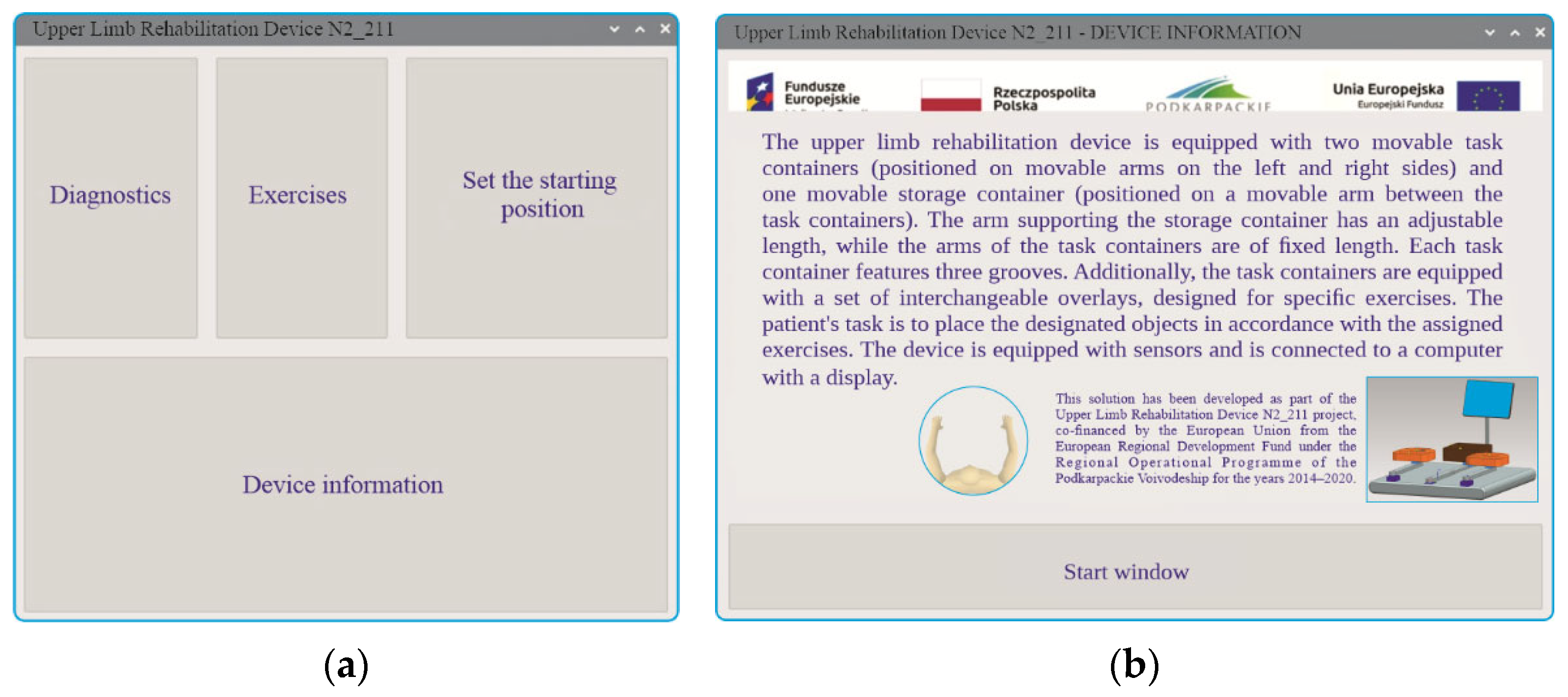
The software controlling the rehabilitation device was developed in Python 3.11.4 using Visual Studio Code (https://code.visualstudio.com/). Upon the system’s startup, a home screen interface appears (Figure 19a), offering several selectable tabs: appraisements, exercises, device reset to initial position, device information. Users may access an information window (Figure 19b), which provides a brief system description and details about the implemented project framework.
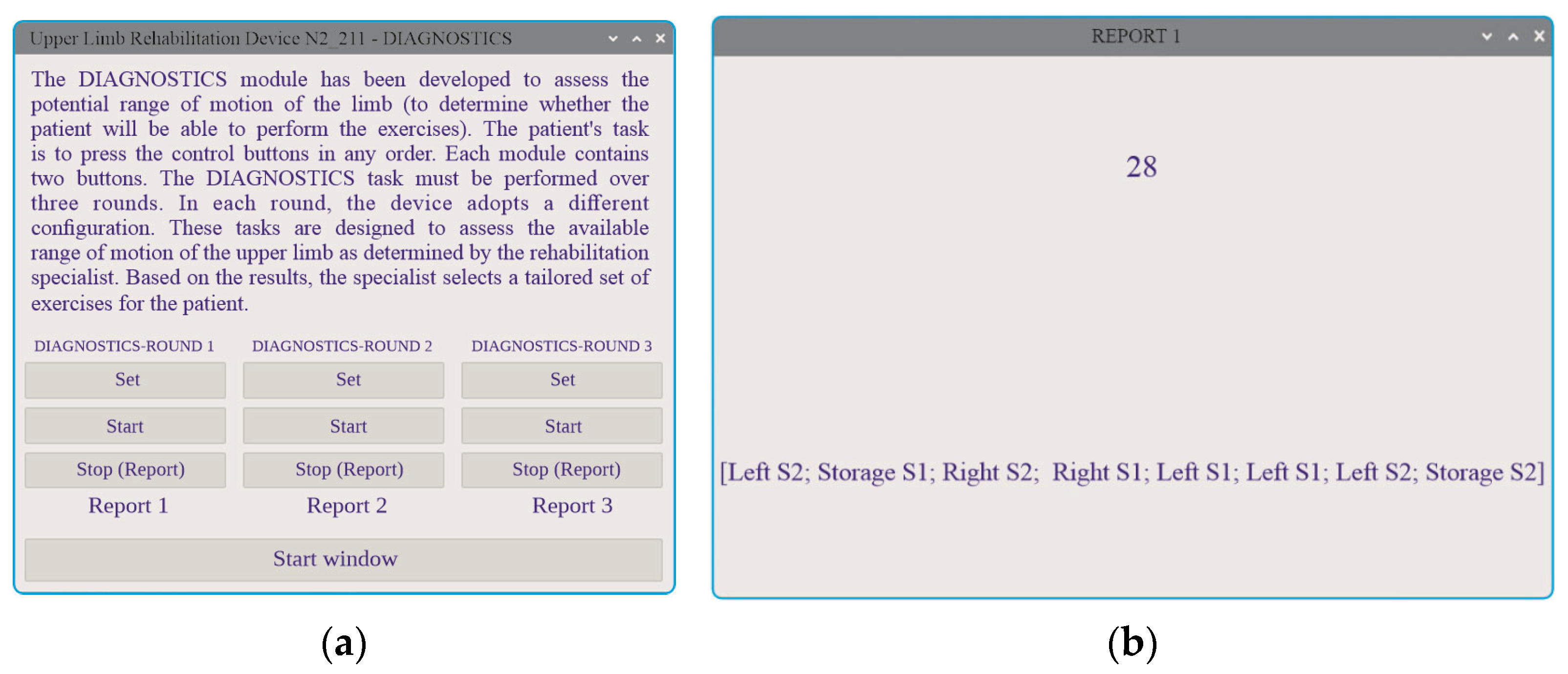
The recommended first step in the system’s use is accessing the appraisements tab (Figure 20a). This tab guides the user through a standardised assessment procedure, consisting of three rounds focused on configuring the device and evaluating basic motor responses. During this step, the user is instructed to press all the control buttons (component No. 10, Figure 1) as quickly as possible. If the individual is unable to complete the task, the therapist may terminate the assessment prematurely using the stop button.
The assessment records both the accuracy and timing of button presses, which serve as initial indicators of the user’s functional motor capacity. The results are automatically compiled and presented in a report format (Figure 20b). By analysing the time elapsed between sensor-detected object placement and the subsequent button press, the system can evaluate whether response consistency has been maintained or varied. This temporal analysis enables the longitudinal monitoring of upper limb motor improvements throughout the rehabilitation process.
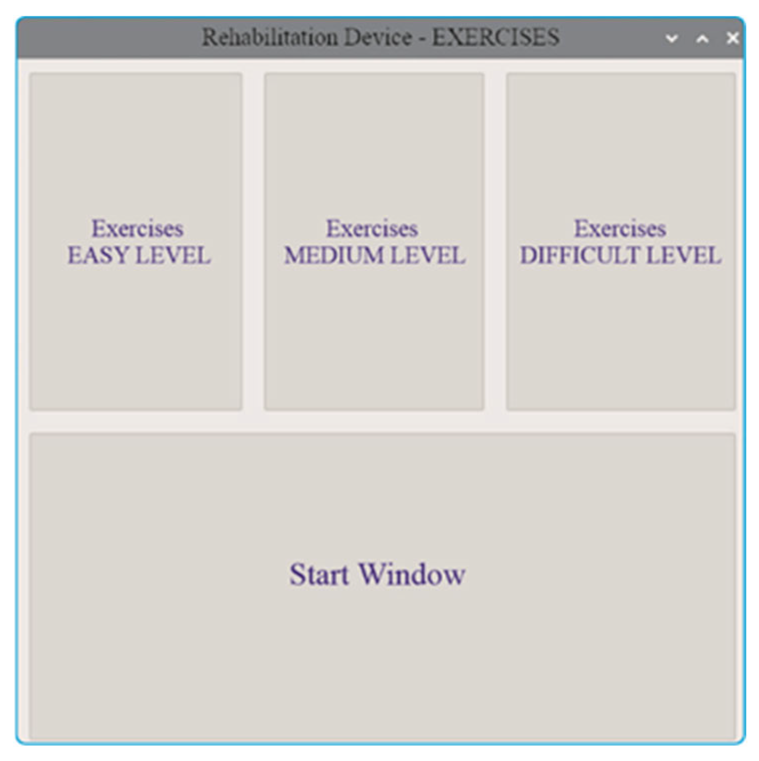
Once the appraisement is completed, the user may proceed to the exercise tab, which presents a range of interactive tasks. The user is required to place objects into illuminated compartments within the storage module, following on-screen instructions. The difficulty level of the exercises can be set to easy, medium, or hard (Figure 21), allowing progressive training tailored to the user’s current abilities.
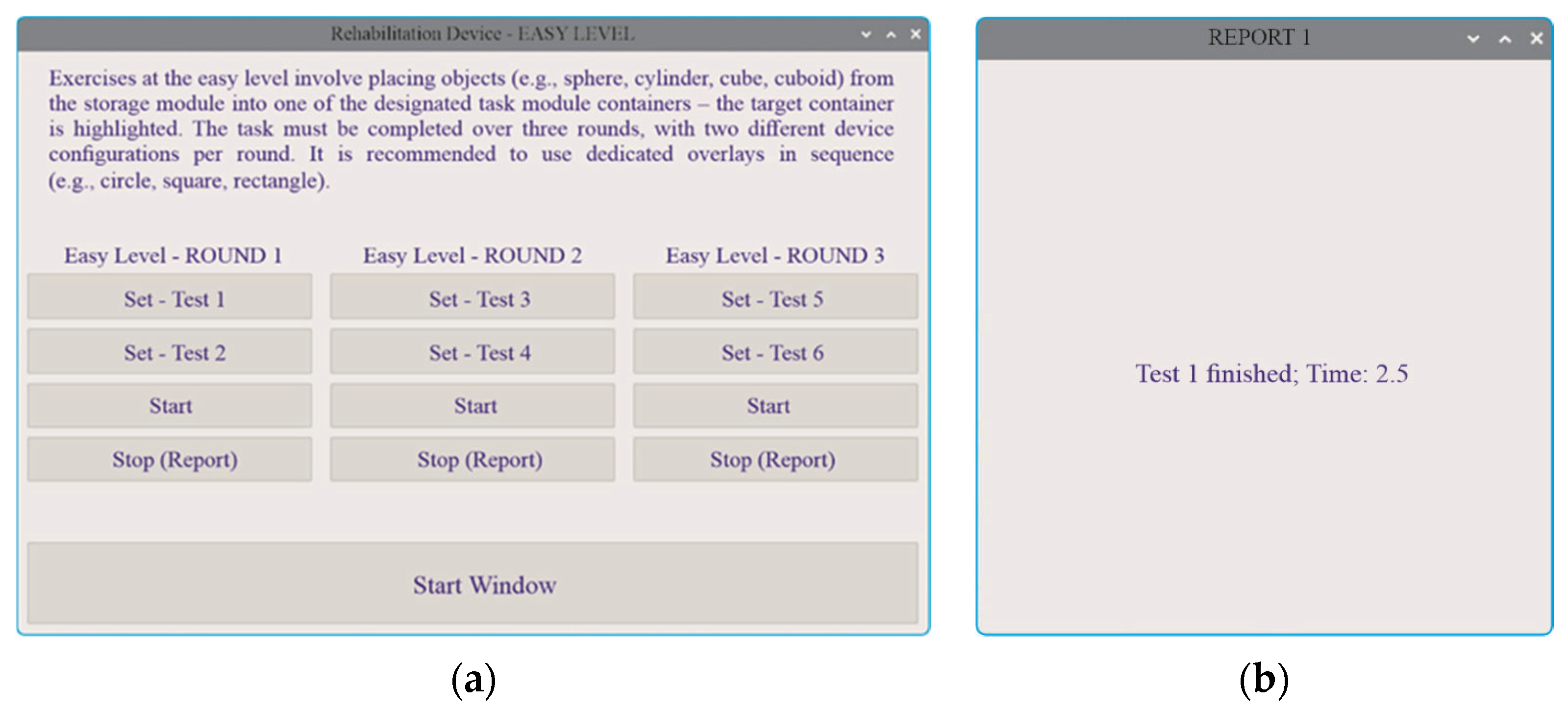
  • Easy Level (Figure 22a)—In this introductory mode, the user selects from different arm configurations and completes object transfers from the central storage to the task modules. The evaluation criteria focus solely on the correct placement of objects in designated compartments. Upon completion of the task, a report and time record for the round are displayed (Figure 22b).
  • Medium Level (Figure 23)—This level introduces an additional cognitive requirement by distinguishing objects based on colour, requiring the user to not only place the object correctly but also select it according to its visual features.
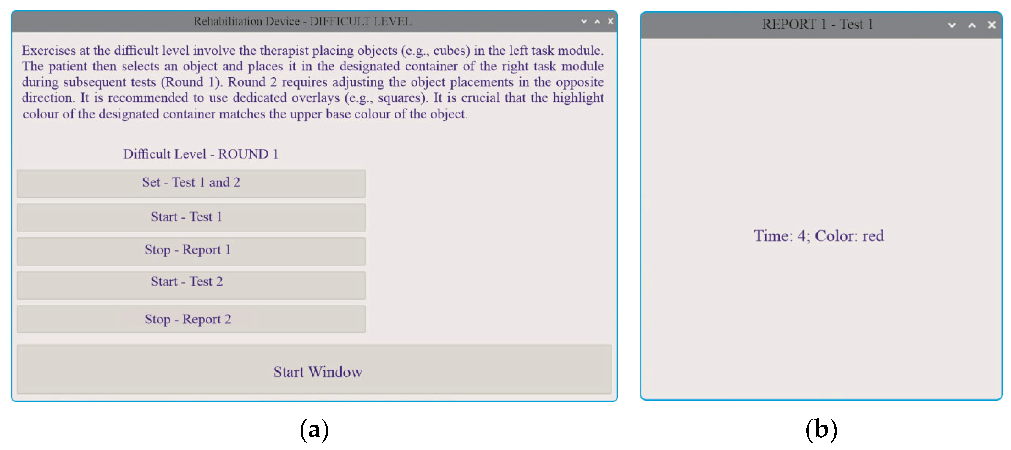
  • Hard Level (Figure 24)—The most advanced mode includes object transfers between the left and right task modules, combined with the requirement to identify dual-coloured side surfaces. This setting challenges both spatial coordination and visual discrimination, offering a comprehensive training scenario.

4.3. Results from Functional Testing of the Device

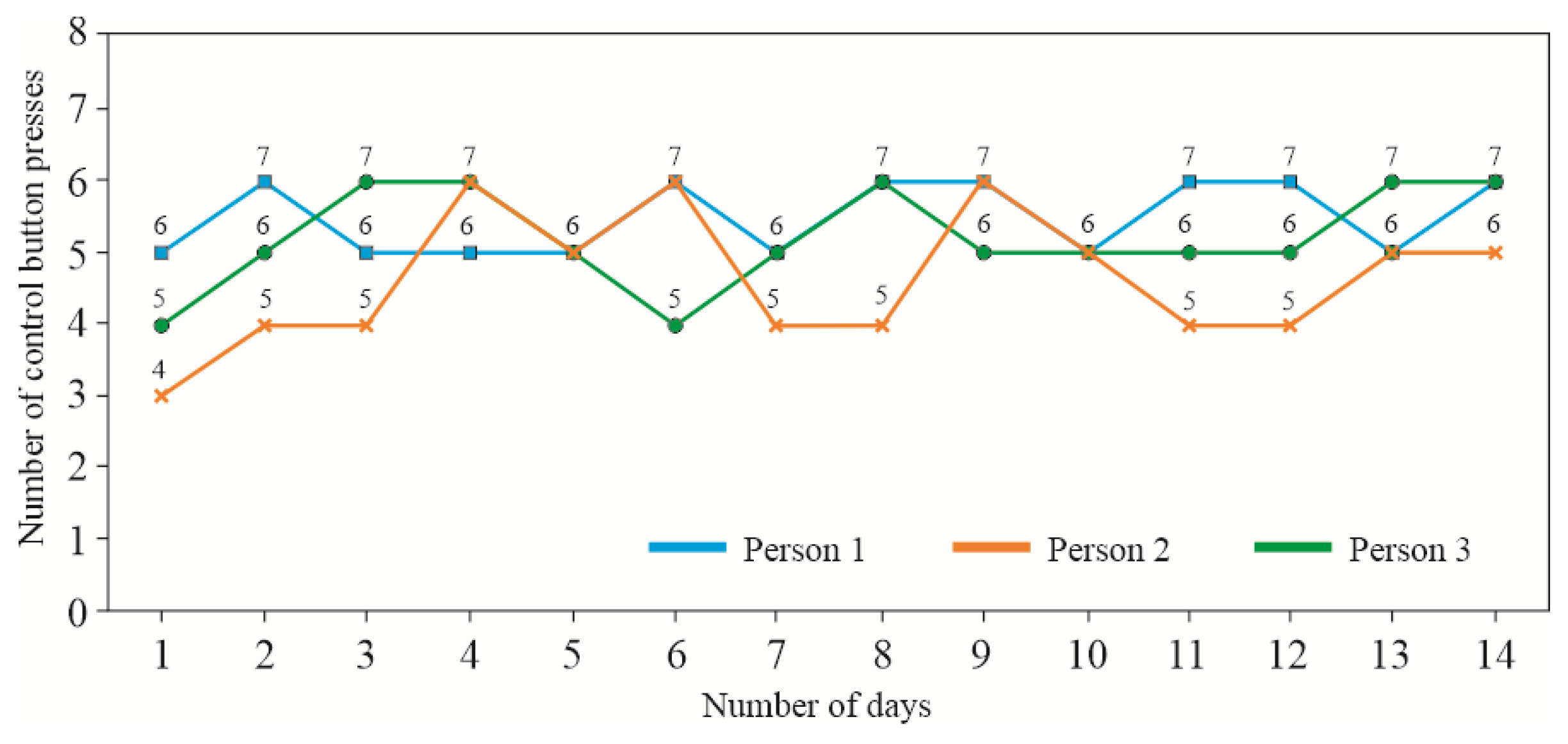
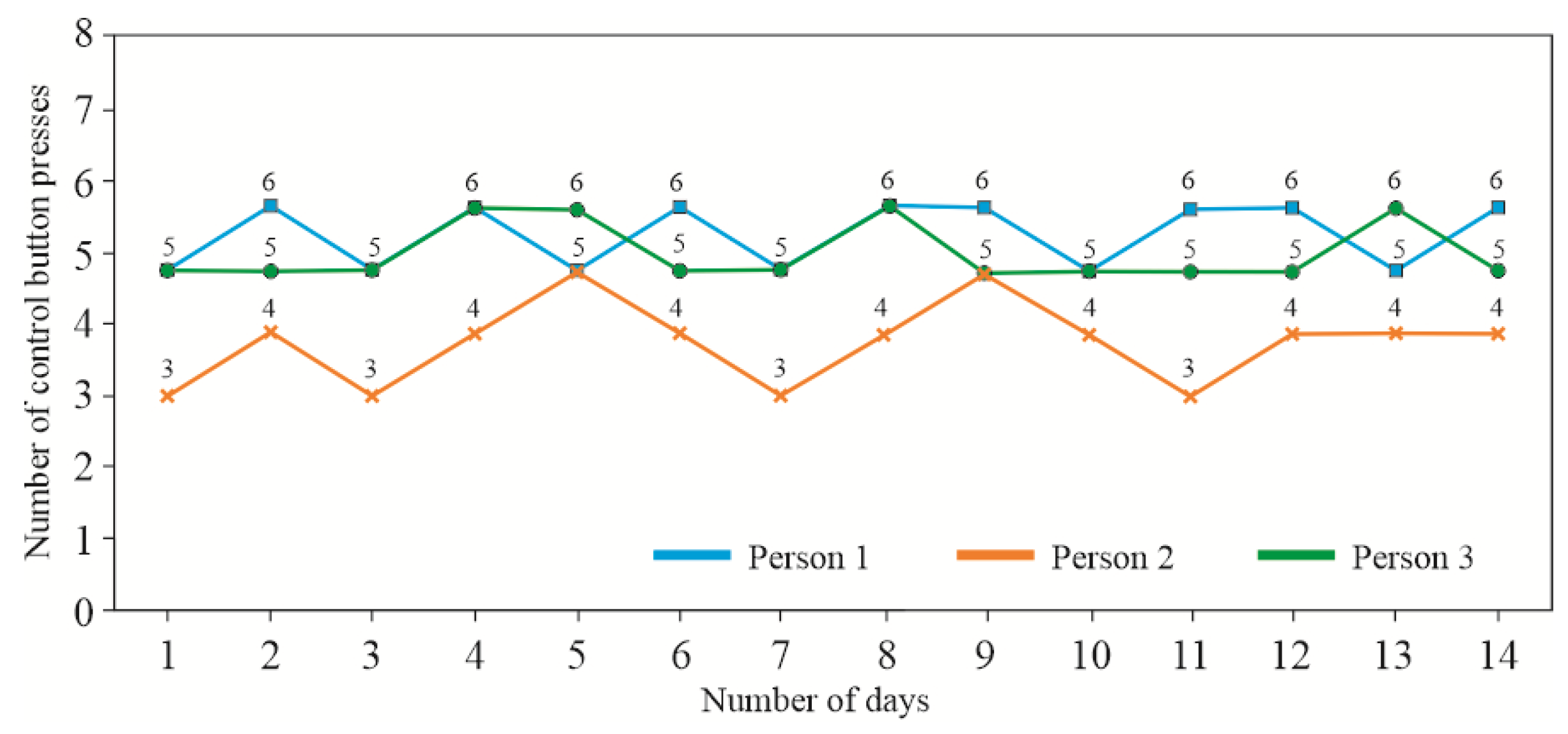
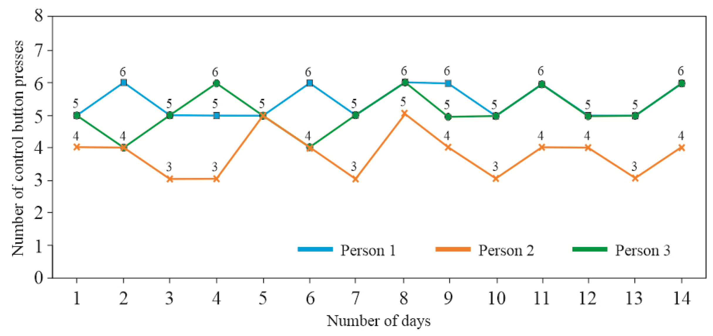
The prototype was tested with three participants aged 39, 67, and 68 years, comprising one female and two male participants. During a one-week testing period, none of the participants reported any issues with the application’s functionality. The recorded data includes errors related to object selection and manipulation, as well as the time required to complete tasks. Figure 25, Figure 26, Figure 27, Figure 28, Figure 29, Figure 30 and Figure 31 present the results of the initial evaluation. The appraisement assessment was conducted over a period of 14 days under three different device configurations (Appraisement—Round 1, Round 2, and Round 3, Figure 20a):
  • Appraisement—Round 1: All three arms of the device (storage module, right task module, and left task module) were aligned at a 0° angle.
  • Appraisement—Round 2: The storage module remained straight (0°), while the task modules were tilted outward at a 30° angle.
  • Appraisement—Round 3: The storage module remained straight (0°), while the task modules were tilted outward at a 60° angle.
Each module was equipped with two control buttons, which the user was required to press in any sequence.
After each individual task involving the transfer of a designated object to the left or right container, the user was required to press a button. Failure to press the button triggered both visual and acoustic signals.
Since the set duration and complexity of sessions could induce fatigue, arm length could also be modified mid-exercise to meet individual needs and ensure completion of the task.
Three sessions were conducted daily with specific arm configurations:
In the graphs (Figure 25, Figure 26 and Figure 27), it is evident that Participant No. 2 performed worse when the task modules were tilted outward. On Days 3, 7, and 11, they managed only three out of six successful button presses. The other participants (Nos. 1 and 3) demonstrated better consistency, with 5–6 presses per session.
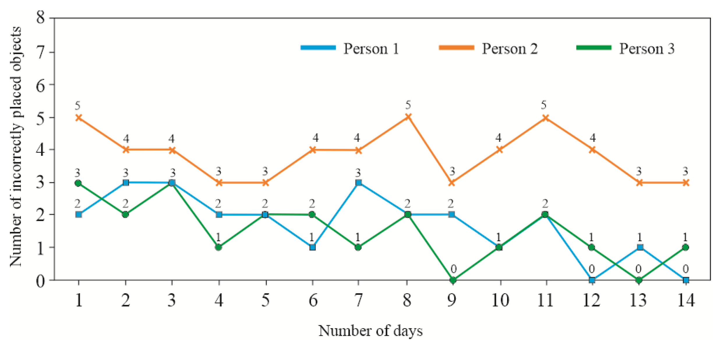
Subsequent tests were performed using a single arm configuration (α = 30°). Figure 28 illustrates a graph based on the results obtained by participants completing tasks at the “easy” difficulty level. During these tasks, participants were required to place spherical objects into designated windows in the task container, utilising attachment No. 3 (Figure 10) and spherical objects (Figure 8). According to Figure 28, Participant No. 2 made approximately 50% errors across eight objects, showing only minor improvement, with their best performance being three errors. Participants Nos. 1 and 3 achieved significantly better outcomes: one error (Participant No. 3) and zero errors (Participant No. 1).
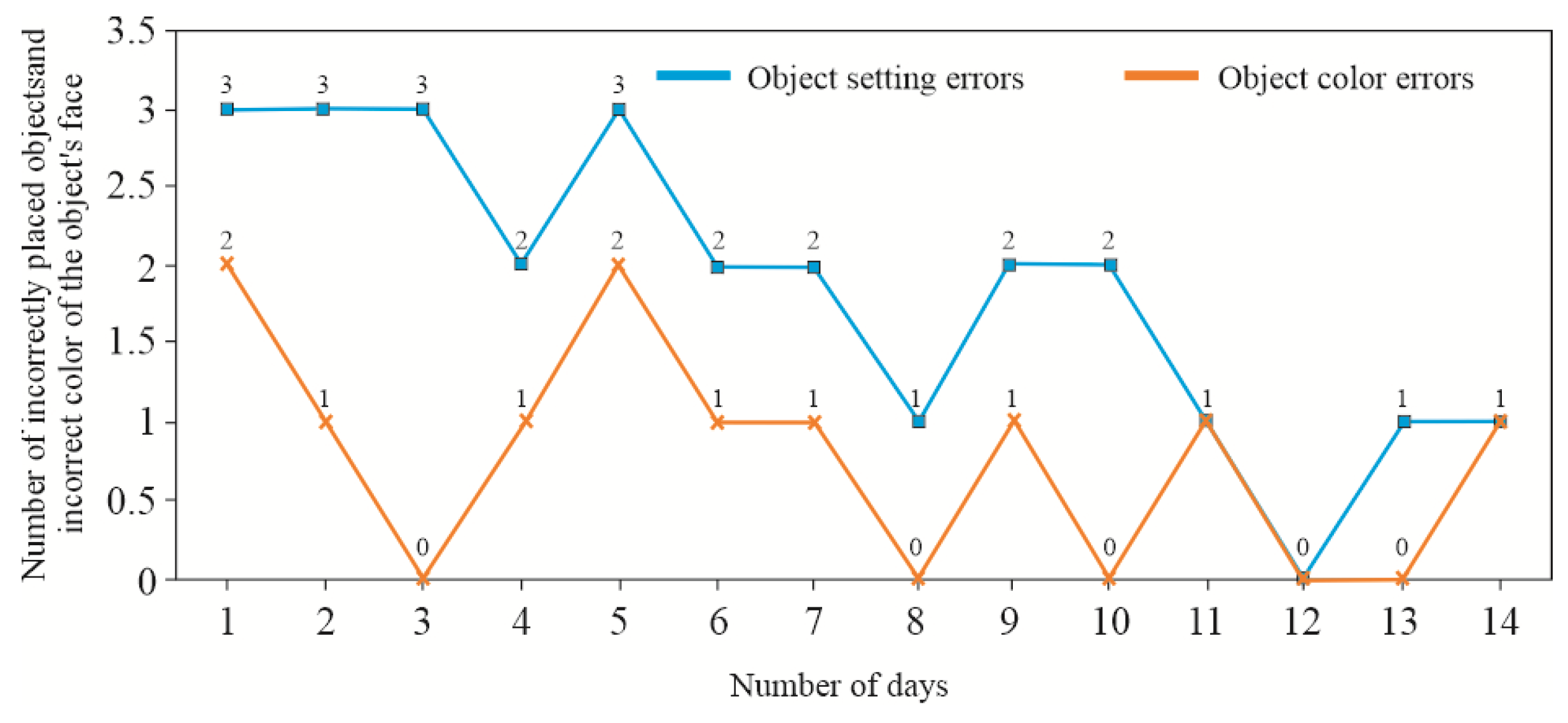
Figure 29, Figure 30 and Figure 31 present the error rates recorded during the 14-day exercise period. Participants were tasked with identifying two specific objects and placing them into correct containers and windows. Each task involved manipulating eight objects. At this level, colour was not verified—only placement and completion time were evaluated (Figure 24).
In cases where an object was incorrectly placed, colour matching was not automatically validated; thus, the colour of the top base was not considered. This was particularly evident for Participant No. 2, who made multiple placement errors while demonstrating relatively few colour identification mistakes. In contrast, Participant No. 1 achieved a high accuracy in both object placement and colour arrangement. Participant No. 3 also performed well in object positioning but experienced some difficulty with wrist orientation and motion control.
The test results indicate that the design and combination of tasks required a relatively high level of dexterity for some users. The variability in performance may have stemmed from limited limb mobility, fatigue, or poor psychophysical condition on the day of testing.
Preliminary testing confirmed that all electronic and mechanical components functioned as intended, with communication protocols operating reliably.

5. Conclusions

This article has presented a prototype mechatronic device and dedicated software designed for upper limb rehabilitation and appraisement, based on the principles of the Box and Block Test (BBT). As the solution is still undergoing development, final technical specifications of the structural components have not been included; the components described herein were primarily utilised for functional testing.
The proposed device is intended to support hand grip rehabilitation and full upper limb movement using the well-established rehabilitation technique of crossed facilitation. A key advantage of the device is its ability to coordinate the rehabilitation of the impaired limb with activity in the unaffected limb.
The user not only practises a range of motion using dedicated manipulation objects but also exercises fine motor functions, including wrist articulation and finger dexterity, by executing precise grips. The manipulation objects vary in shape, size, material, and surface complexity. These features are designed to stimulate tactile receptors in the hand and fingers, thereby accelerating rehabilitation. Furthermore, the use of coloured and numbered objects enhances user engagement, potentially making therapy more effective and enjoyable than conventional methods.
The device also supports the implementation of biofeedback-based rehabilitation. In selected scenarios, exercises require simultaneous bimanual coordination. The development of additional interchangeable overlays for the task modules has enhanced the device’s functionality and enabled the creation of manipulation objects tailored to users at various stages of recovery.
The system’s microcomputer and integrated software modules provide broad compatibility with peripheral input/output devices. Future developments will include a network communication module to enable remote operation and cloud-based data storage.
A sound communication interface will also be integrated, featuring speech recognition and voice-guided assistance, particularly for users with speech impairments. Moreover, the software will incorporate a personalised settings management tool, allowing therapists to adapt exercises to the anatomical characteristics of individual users. Visualisation of progress and results—stored locally or in the cloud—will be supported.
The device’s compact design allows for easy assembly and disassembly, facilitating use in a variety of settings convenient to the user. Future development will focus on further optimising the structural design and software to produce a more portable and anthropomorphic device. The rehabilitation setup will also accommodate semi-reclined positions, allowing exercises to be performed in bed.
Control buttons will be redesigned within a separate housing, which can be positioned according to user preference. Communication between the buttons and the microcontroller will be wireless (Bluetooth), and the button positions will be adjustable to alter tasks’ difficulty. This flexibility is intended to prevent habituation to fixed response patterns, promoting neuromuscular adaptation through a progressive variation in task challenges across training sessions.

Author Contributions

Conceptualisation, J.S.T. and J.M.; methodology, J.S.T. and J.M.; software, J.S.T.; validation, J.S.T.; formal analysis, J.M.; investigation, J.S.T.; data curation, J.S.T.; writing—original draft preparation, J.S.T. and J.M.; writing—review and editing, J.M.; visualisation, J.M.; supervision, J.M.; project administration, J.S.T. All authors have read and agreed to the published version of the manuscript.

Funding

The work presented in this publication was carried out with funding from grant No. N2_211, “Upper Limb Rehabilitation Device”, provided by the Podkarpackie Centre for Innovation in Rzeszów. The grant programme for the R&D activities of scientific units is part of the project entitled “Podkarpackie Centre for Innovation”, co-financed by the European Regional Development Fund under Priority Axis 1 “Competitiveness and Innovative Economy” of the Regional Operational Programme of the Podkarpackie Voivodeship for the years 2014–2020.

Institutional Review Board Statement

Not applicable.

Informed Consent Statement

Not applicable.

Data Availability Statement

The original contributions presented in this study are included in the article. Further inquiries can be directed to the corresponding author.

Conflicts of Interest

The authors declare no conflicts of interest.

References

  1. Katan, M.; Luft, A. Global Burden of Stroke. Semin. Neurol. 2018, 38, 208–211. [Google Scholar] [CrossRef] [PubMed]
  2. Available online: https://www.world-stroke.org/ (accessed on 23 April 2025).
  3. Kwolek, A. Medical Rehabilitation, 2nd ed.; Elsevier Urban & Partner: Wrocław, Poland, 2003; ISBN 9788376093130. (In Polish) [Google Scholar]
  4. Grabowska-Fudala, B.; Jaracz, K.; Górna, K. Stroke incidence, case fatality and mortality—Current trends and future prognosis. Prz. Epidemiol. 2010, 64, 439–442. [Google Scholar]
  5. Bártlová, S.; Šedová, L.; Havierniková, L.; Hudáčková, A.; Dolák, F.; Sadílek, P. Quality of life of post-stroke patients. Slov. J. Public Health 2022, 61, 101–108. [Google Scholar] [CrossRef]
  6. Siger, A. (Ed.) The Situation of People After Stroke in Poland—A Report of the Stroke Foundation; The Stroke Foundation: Łódź, Poland, 2024; Available online: https://fum.info.pl/raport_osoby_po_udarze_e.pdf (accessed on 23 April 2025).
  7. Stroke Association. What We Think About: Rehabilitation. Rebuilding Lives After Stroke; Stroke Association: London, UK, 2023; Available online: https://www.stroke.org.uk/sites/default/files/new_pdfs_2019/our_policy_position/rehabilitation_policy_position.pdf (accessed on 23 April 2025).
  8. Feigin, V.L.; Forouzanfar, M.H.; Krishnamurthi, R.; Mensah, G.A.; Connor, M.; Bennett, D.A.; Moran, A.E.; Sacco, R.L.; Anderson, L.; Truelsen, T.; et al. Global and regional bur den of stroke during 1990–2010: Findings from the Global Burden of Disease Study 2010. Lancet 2014, 383, 245–255. [Google Scholar] [CrossRef]
  9. Seshadri, S.; Wolf, A. Lifetime risk of stroke and dementia: Current concepts, and estimates from the framingham study. Lancet Neurol. 2017, 6, 1106–1114. [Google Scholar] [CrossRef]
  10. Mohan, K.M.; Wolfe, C.D.; Rudd, A.G.; Heuschmann, P.U.; Kolominsky-Rabas, P.L.; Grieve, A.P. Risk and cumulative risk of stroke recurrence: A systematic review and meta-analysis. Stroke 2011, 42, 1489–1494. [Google Scholar] [CrossRef]
  11. National Center for Health Statistics. Health, United States, 2011: With Special Feature on Socioeconomic Status and Health; National Center for Health Statistics: Hyattsville, MD, USA, 2012. Available online: https://www.cdc.gov/nchs/data/hus/hus11.pdf (accessed on 10 December 2024).
  12. O’Donnell, M.J.; Xavier, D.; Liu, L.; Zhang, H.; Chin, S.L.; Rao-Melacini, P.; Rangarajan, S.; Islam, S.; Pais, P.; McQueen, M.J.; et al. Risk factors for ischaemic and intracerebral haemorrhagic stroke in 22 countries (the INTERSTROKE study): A case-control study. Lancet 2010, 376, 112–123. [Google Scholar] [CrossRef]
  13. Reeves, M.J.; Bushnell, C.D.; Howard, G.; Gargano, J.W.; Duncan, P.W.; Lynch, G.; Khatiwoda, A.; Lisabeth, L. Sex differences in stroke: Epidemiology, clinical presentation, medical care, and outcomes. Lancet Neurol. 2008, 7, 915–926. [Google Scholar] [CrossRef]
  14. Peterson, B.L.; Won, S.; Geddes, R.I.; Sayeed, I.; Stein, D.G. Sex-related differences in effects of progesterone following neonatal hypoxic brain injury. Behav. Brain Res. 2015, 286, 152–165. [Google Scholar] [CrossRef]
  15. Shahid, J.; Kashif, A.; Kashif-Shahid, M. A Comprehensive Review of Physical Therapy Interventions for Stroke Rehabilitation: Impairment-Based Approaches and Functional Goals. Brain Sci. 2023, 13, 717. [Google Scholar] [CrossRef]
  16. Pu, L.; Wang, L.; Zhang, R.; Zhao, T.; Jiang, Y.; Han, L. Projected Global Trends in Ischemic Stroke Incidence, Deaths and Disability-Adjusted Life Years From 2020 to 2030. Stroke 2023, 54, 1330–1339. [Google Scholar] [CrossRef] [PubMed]
  17. Cheng, Y.; Lin, Y.; Shi, H.; Cheng, M.; Zhang, B.; Liu, X.; Shi, C.; Wang, Y.; Xia, C.; Xie, W. Projections of the Stroke Burden at the Global, Regional, and National Levels up to 2050 Based on the Global Burden of Disease Study 2021. J. Am. Heart Assoc. 2024, 13, e036142. [Google Scholar] [CrossRef] [PubMed]
  18. WHO. Stroke, Cerebrovascular Accident. 2025. Available online: https://www.emro.who.int/health-topics/stroke-cerebrovascular-accident/index.html (accessed on 20 April 2025).
  19. American Heart Association. Stroke Symptoms. 2025. Available online: https://www.stroke.org/en/about-stroke/stroke-symptoms (accessed on 17 April 2025).
  20. Andersson, J.; Rejnö, Å.; Jakobsson, S.; Hansson, P.-O.; Nielsen, S.J.; Björck, L. Symptoms at stroke onset as described by patients: A qualitative study. BMC Neurol. 2024, 24, 150. [Google Scholar] [CrossRef] [PubMed]
  21. Tater, P.; Pandey, S. Post-stroke Movement Disorders: Clinical Spectrum, Pathogenesis, and Management. Neurol. India 2021, 69, 272–283. [Google Scholar] [CrossRef]
  22. Lewek, M.D.; Bradley, C.E.; Wutzke, C.J.; Zinder, S.M. The relationship between spatiotemporal gait asymmetry and balance in individuals with chronic stroke. J. Appl. Biomech. 2014, 30, 31–36. [Google Scholar] [CrossRef]
  23. Lewek, M.D.; Randall, E.P. Reliability of spatiotemporal asymmetry during overground walking for individuals following chronic stroke. J. Neurol. Phys. Ther. 2011, 35, 116–121. [Google Scholar] [CrossRef]
  24. Patterson, K.K.; Gage, W.H.; Brooks, D.; Black, S.E.; McIlroy, W.E. Evaluation of gait symmetry after stroke: A comparison of current methods and recommendations for standardization. Gait Posture 2010, 31, 241–246. [Google Scholar] [CrossRef]
  25. Jamal, K.; Leplaideur, S.; Rousseau, C.; Chochina, L.; Moulinet-Raillon, A.; Bonan, I. Disturbances of spatial reference frame and postural asymmetry after a chronic stroke. Exp. Brain Res. 2018, 236, 2377–2385. [Google Scholar] [CrossRef]
  26. Hatem, S.M.; Saussez, G.; Della-Faille, M.; Prist, V.; Zhang, X.; Dispa, D.; Bleyenheuft, Y. Rehabilitation of Motor Function after Stroke: A Multiple Systematic Review Focused on Techniques to Stimulate Upper Extremity Recovery. Front. Hum. Neurosci. 2016, 10, 442. [Google Scholar] [CrossRef]
  27. Kwakkel, G.; Stinear, C.; Essers, B.; Munoz-Novoa, M.; Branscheidt, M.; Cabanas-Valdés, R.; Lakičević, S.; Lampropoulou, S.; Luft, A.R.; Marque, R.; et al. Motor rehabilitation after stroke: European Stroke Organisation (ESO) consensus-based definition and guiding framework. Eur. Stroke J. 2023, 8, 880–894. [Google Scholar] [CrossRef]
  28. Lee, K.E.; Choi, M.; Jeoung, B. Effectiveness of Rehabilitation Exercise in Improving Physical Function of Stroke Patients: A Systematic Review. Int. J. Environ. Res. Public Health 2022, 19, 12739. [Google Scholar] [CrossRef] [PubMed]
  29. Han, P.; Zhang, W.; Kang, L.; Ma, Y.; Fu, L.; Jia, L.; Yu, H.; Chen, X.; Hou, L.; Wang, L.; et al. Clinical Evidence of Exercise Benefits for Stroke. Adv. Exp. Med. Biol. 2017, 1000, 131–151. [Google Scholar] [CrossRef]
  30. Chen, K.; Zhu, S.; Tang, Y.; Lan, F.; Liu, Z. Advances in balance training to prevent falls in stroke patients: A scoping review. Front. Neurol. 2024, 15, 1167954. [Google Scholar] [CrossRef]
  31. Lee, C.Y.; Howe, T.H. Effectiveness of Activity-Based Task-Oriented Training on Upper Extremity Recovery for Adults with Stroke: A Systematic Review. Am. J. Occup. Ther. 2024, 78, 7802180070. [Google Scholar] [CrossRef]
  32. Maciejasz, P.; Eschweiler, J.; Gerlach-Hahn, K.; Jansen-Troy, A.; Leonhardt, S. A survey on robotic devices for upper limb rehabilitation. J. Neuroeng. Rehabil. 2014, 11, 3. [Google Scholar] [CrossRef]
  33. Laut, J.; Porfiri, M.; Raghavan, P. The Present and Future of Robotic Technology in Rehabilitation. Curr. Phys. Med. Rehabil. Rep. 2016, 4, 312–319. [Google Scholar] [CrossRef]
  34. Colombo, R.; Pisano, F.; Micera, S.; Mazzone, A.; Delconte, C.; Carrozza, M.C.; Dario, P.; Minuco, G. Robotic Techniques for Upper Limb Evaluation and Rehabilitation of Stroke Patients. IEEE Trans. Neural Syst. Rehabil. Eng. 2005, 13, 311–324. [Google Scholar] [CrossRef]
  35. Mazzoleni, S.; Dario, P.; Carrozza, M.; Guglielmelli, E. Application of Robotic and Mechatronic Systems to Neurorehabilitation. In Mechatronic Systems Applications, 1st ed.; Milella, A., Di Paola, D., Cicirelli, G., Eds.; IntechOpen: London, UK, 2010; pp. 99–116. [Google Scholar] [CrossRef]
  36. Banyai, A.D.; Brisan, C. Robotics in Physical Rehabilitation: Systematic Review. Healthcare 2024, 12, 1720. [Google Scholar] [CrossRef]
  37. Martins, O.O.; Oosthuizen, C.C.; Desai, D.A. Exploring the import of mechatronics engineering in medicine: A review. Beni-Suef. Univ. J. Basic. Appl. Sci. 2025, 14, 26. [Google Scholar] [CrossRef]
  38. Dovat, L.; Lambercy, O.; Gassert, R.; Maeder, T.; Milner, T.; Leong, T.C.; Burdet, E. HandCARE: A cable-actuated rehabilitation system to train hand function after stroke. IEEE Trans. Neural Syst. Rehabil. Eng. 2008, 16, 582–591. [Google Scholar] [CrossRef]
  39. Ramos-Murguialday, A.; Broetz, D.; Rea, M.; Laer, L.; Yilmaz, O.; Brasil, F.L.; Liberati, G.; Curado, M.R.; Garcia-Cossio, E.; Vyziotis, A.; et al. Brain-machine interface in chronic stroke rehabilitation: A controlled study. Ann. Neurol. 2013, 74, 100–108. [Google Scholar] [CrossRef] [PubMed]
  40. Fazekas, G.; Horwath, M.; Toth, A. A novel robot training system designed to supplement upper limb physiotherapy on patient with spastic hemiparesis. Int. J. Rehabil. Res. 2006, 29, 251–254. [Google Scholar] [CrossRef] [PubMed]
  41. Ferris, D.P. The exoskeletons are here. J. Neuroeng. Rehabil. 2009, 6, 17. [Google Scholar] [CrossRef] [PubMed]
  42. Pignolo, L.; Dolce, G.; Basta, G.; Lucca, L.F.; Serra, S.; Sannitam, W.G. Upper limb rehabilitation after stroke. ARAMIS a ‘robo-mechatronic’ innovative approach and prototype. In Proceedings of the 4th IEEE RAS & EMBS International Conference on Biomedical Robotics and Biomechatronics (BioRob), Rome, Italy, 24–27 June 2012; pp. 1410–1414. [Google Scholar] [CrossRef]
  43. Frisoli, A.; Borelli, L.; Montagner, A.; Marcheschi, S.; Procopio, C.; Salsedo, F.; Bergamasco, M.; Carboncini, M.C. Arm rehabilitation with a robotic exoskeleton in virtual reality. In Proceedings of the IEEE 10th International Conference on Rehabilitation and Robotics (ICORR), Noordwijk, The Netherlands, 13–15 June 2007; pp. 631–642. [Google Scholar] [CrossRef]
  44. Frolov, A.A.; Gusek, D.; Sil’chenko, A.V.; Tintera, Y.; Rydlo, Y. The Changes in the hemodynamic activity of the brain in motor imagery as a result of training subjects to control a brain-computer interface. Fiziol. Cheloveka 2016, 42, 5–18. [Google Scholar]
  45. Marchal-Crespo, L.; Reinkensmeyer, D.J. Review of control strategies for robotic movement training after neurologic injury. J. Neuroeng. Rehabil. 2009, 6, 20. [Google Scholar] [CrossRef]
  46. Desplenter, T.; Zhou, Y.; Edmonds, B.; Lidka, M.; Goldman, A.; Trejos, A.L. Rehabilitative and assistive wearable mechatronic upper-limb devices: A review. J. Rehabil. Assist. Technol. Eng. 2020, 7, 2055668320917870. [Google Scholar] [CrossRef]
  47. Just, F.; Baur, K.; Riener, R.; Klamroth-Marganska, V.; Rauter, G. Online adaptive compensation of the ARMin Rehabilitation Robot. In Proceedings of the 6th IEEE International Conference on IEEE 2016, Biomedical Robotics and Biomechatronics (BioRob), Singapore, 26–29 June 2016; pp. 747–752. [Google Scholar] [CrossRef]
  48. Ren, H.; Liu, T.; Wang, J. Design and Analysis of an Upper Limb Rehabilitation Robot Based on Multimodal Control. Sensor 2023, 23, 8801. [Google Scholar] [CrossRef]
  49. Ventura, S.; Tessari, A.; Castaldini, S.; Magni, E.; Turolla, A.; Baños, R.; Lullini, G. Effectiveness of a Virtual Reality rehabilitation in stroke patients with sensory-motor and proprioception upper limb deficit: A study protocol. PLoS ONE 2024, 19, e0307408. [Google Scholar] [CrossRef]
  50. Ren, Y.; Park, H.S.; Zhang, L.Q. Developing a whole-arm exoskeleton robot with hand opening and closing mechanism for upper limb stroke rehabilitation. In Proceedings of the IEEE International Conference on Rehabilitation Robotics (ICORR), Kyoto, Japan, 23–26 June 2009; pp. 761–765. [Google Scholar] [CrossRef]
  51. Dipietro, L.; Ferraro, M.; Palazzolo, J.J.; Krebs, H.I.; Volpe, B.T.; Hogan, N. Customized interactive robotic treatment for stroke: EMG triggered therapy. IEEE Trans. Neur. Syst. Rehab. Eng. 2005, 13, 325–334. [Google Scholar] [CrossRef]
  52. Shih, J.; Krusienski, D.J.; Wolpaw, J.W. Brain-computer interfaces in medicine. Mayo Clin. Proc. 2012, 87, 268–279. [Google Scholar] [CrossRef]
  53. Hesse, S.; Kuhlmann, H.; Wilk, J.; Tomelleri, C.; Kirker, S.G.B. A new electromechanical trainer for sensorimotor rehabilitation of paralysed fingers: A case series in chronic and acute stroke patients. J. Neuroeng. Rehabil. 2008, 5, 21. [Google Scholar] [CrossRef] [PubMed]
  54. Frolov, A.A.; Mokienko, O.; Lyukmanov, R.; Biryukova, E.; Kotov, S.; Turbina, L.; Nadareyshvily, G.; Bushkova, Y. Post-stroke Rehabilitation Training with a Motor-Imagery-Based Brain-Computer Interface (BCI)-Controlled Hand Exoskeleton: A Randomized Controlled Multicenter Trial. Front. Neurosci. 2017, 11, 400. [Google Scholar] [CrossRef] [PubMed]
  55. Panny, M.; Mayr, A.; Nagiller, M.; Kim, Y. A domestic robotic rehabilitation device for assessment of wrist function for outpatients. J. Rehabil. Assist. Technol. Eng. 2020, 7, 2055668320961233. [Google Scholar] [CrossRef]
  56. Forbrigger, S.; DePaul, V.G.; Davies, T.C.; Morin, E.; Hashtrudi Zaad, K. Home based upper limb stroke rehabilitation mechatronics: Challenges and opportunities. Biomed. Eng. 2023, 22, 67. [Google Scholar] [CrossRef]
  57. Ruggiu, M.; Rea, P. Development of a Mechatronic System for the Mirror Therapy. Actuators 2022, 11, 14. [Google Scholar] [CrossRef]
  58. Akshay, M.; Latt, W.T.; Tan, H.G.; Tan, U.X.; Shee, C.Y.; Ang, W.T. Design and implementation of a mechatronic device for wrist and elbow rehabilitation. In Proceedings of the 1st International Convention on Rehabilitation Engineering & Assistive Technology: In Conjunction with 1st Tan Tock Seng Hospital Neurorehabilitation Meeting i-CREATe ‘07, Singapore, 23–26 April 2007; Association for Computing Machinery: New York, NY, USA, 2007; pp. 212–215. [Google Scholar] [CrossRef]
  59. Kyeong, S.; Na, Y.; Kim, J. A Mechatronic Mirror-Image Motion Device for Symmetric Upper-Limb Rehabilitation. Int. J. Precis. Eng. Manuf. 2020, 21, 947–956. [Google Scholar] [CrossRef]
  60. Averta, G.; Abbinante, M.; Orsini, P.; Felici, F.; Lippi, P.; Bicchi, A.; Catalano, M.G.; Bianchi, M. A novel mechatronic system for evaluating elbow muscular spasticity relying on Tonic Stretch Reflex Threshold estimation. In Proceedings of the Annual International Conference of the IEEE Engineering in Medicine & Biology Society, Montreal, QC, Canada, 20–24 July 2020; pp. 3839–3843. [Google Scholar] [CrossRef]
  61. Cavallaro, E.; Keller, T. Portable Device for Upper Limb Rehabilitation. U.S. Patent 8795207B2, 5 August 2014. [Google Scholar]
  62. Bimeo: An Award-Winning, Sensor-Based, Arm Rehabilitation System. Available online: https://kinestica.com/bimeo (accessed on 14 December 2024).
  63. Pablo: Functional Rehabilitation. Available online: https://tyromotion.com/en/products/pablo/ (accessed on 14 December 2024).
  64. Myro: Interactive and Task-Specific Therapy. Available online: https://tyromotion.com/en/products/myro (accessed on 14 December 2024).
  65. Annett, M.; Anderson, F.; Goertzen, D.; Halton, J.; Bischof, Q.R.W.F.; Boulanger, P. Using a Multi-touch Tabletop for Upper Extremity Motor Rehabilitation. In Proceedings of the 21st Annual Conference of the Australian Computer-Human Interaction Special Interest Group: Design: Open 24/7 (OZCHI ‘09), Melbourne Australia, 23–27 November 2009; Association for Computing Machinery: New York, NY, USA, 2009; pp. 261–264. [Google Scholar] [CrossRef]
  66. Kim, G.W.; Won, Y.H.; Seo, J.H.; Ko, M.H. Effects of newly developed compact robot-aided upper extremity training system (Neuro-X®) in patients with stroke: A pilot study. J. Rehabil. Med. 2018, 50, 607–612. [Google Scholar] [CrossRef]
  67. Kim, S.-Y.; Kim, Y.-M.; Koo, S.-W.; Park, H.-B.; Yoon, Y.-S. Effects of Therapist Intervention during Upper-Extremity Robotic Rehabilitation in Patients with Stroke. Healthcare 2023, 11, 1369. [Google Scholar] [CrossRef]
  68. Tunc, H.; Bakar, M.K.; Ozen, S.; Leblebici, G.; Tarakci, D. The effect of virtual reality applications on treatment outcomes in lower extremity rehabilitation: A systematic review. Adv. Rehabil. 2024, 38, 43–57. [Google Scholar] [CrossRef]
  69. Zahabi, M.; Abdul-Razak, A.M. Adaptive virtual reality-based training: A systematic literature review and framework. Virtual Real. 2020, 24, 725–752. [Google Scholar] [CrossRef]
  70. Vosinakis, S.; Koutsabasis, P. Evaluation of visual feedback techniques for virtual grasping with bare hands using Leap Motion and Oculus Rift. Virtual Real. 2018, 22, 47–62. [Google Scholar] [CrossRef]
  71. Dong, Y.; Liu, X.; Tang, M.; Huo, H.; Chen, D.; Wu, Z.; An, R.; Fan, Y. A haptic feedback virtual reality system to improve the Box and Block Test (BBT) for upper extremity motor function assessment. Virtual Real. 2023, 27, 1199–1219. [Google Scholar] [CrossRef]
  72. Alvarez-Rodríguez, M.; López-Dolado, E.; Salas-Monedero, M.; Lozano-Berrio, V.; Ceruelo-Abajo, S.; Gil-Agudo, A.; de los Reyes-Guzmán, A. Concurrent Validity of a Virtual Version of Box and Block Test for Patients with Neurological Disorders. World J. Neurosci. 2020, 10, 79–89. [Google Scholar] [CrossRef]
  73. Everard, G.; Otmane-Tolba, Y.; Rosselli, Z.; Pellissier, T.; Ajana, K.; Dehem, S.; Auvinet, E.; Edwards, M.G.; Lebleu, J.; Lejeune, T. Concurrent validity of an immersive virtual reality version of the Box and Block Test to assess manual dexterity among patients with stroke. J. Neuroeng. Rehabil. 2022, 19, 7. [Google Scholar] [CrossRef]
  74. Gieser, S.N.; Gentry, C.; LePage, J.; Makedon, F. Comparing objective and subjective metrics between physical and virtual tasks. In Virtual, Augmented and Mixed Reality, Proceedings of the VAMR 2016, Toronto, Canada, 17–22 July 2016; Lackey, S., Shumaker, R., Eds.; Lecture Notes in Computer Science; Springer: Cham, Switzerland, 2016; pp. 3–13. [Google Scholar] [CrossRef]
  75. Oña, E.D.; Jardón, A.; Balaguer, C. The Automated Box and Blocks Test an Autonomous Assessment Method of Gross Manual Dexterity in Stroke Rehabilitation. In Towards Autonomous Robotic Systems, Proceedings of the TAROS 2017, Guildford, UK, 19–21 July 2017; Gao, Y., Fallah, S., Jin, Y., Lekakou, C., Eds.; Lecture Notes in Computer Science; Springer: Cham, Switzerland, 2017; Volume 10454, pp. 3–13. [Google Scholar] [CrossRef]
  76. Oña, E.D.; Jardón, A.; Cuesta-Gómez, A.; Sánchez-Herrera-Baeza, P.; Canode-la-Cuerda, R.; Balaguer, C. Validity of a fully-immersive VR-based version of the box and blocks test for upper limb function assessment in Parkinson’s disease. Sensors 2020, 20, 2773. [Google Scholar] [CrossRef]
  77. Furmanek, M.P.; Schettino, L.F.; Yarossi, M.; Kirkman, S.; Adamovich, S.V.; Tunik, E. Coordination of reach-to-grasp in physical and haptic-free virtual environments. J. Neuroeng. Rehabil. 2019, 16, 78. [Google Scholar] [CrossRef]
  78. Oña, E.D.; Balaguer, C.; Jardón, A. Automatic Cube Counting System for the Box and Blocks Test Using Proximity Sensors: Development and Validation. Electronics 2023, 12, 914. [Google Scholar] [CrossRef]
  79. Temehy, B.; Rosewilliam, S.; Alvey, G.; Soundy, A. Exploring Stroke Patients’ Needs after Discharge from Rehabilitation Centres: Meta-Ethnography. Behav. Sci. 2022, 12, 404. [Google Scholar] [CrossRef]
  80. Mitchell, J.; Shirota, C.; Clanchy, K. Factors that influence the adoption of rehabilitation technologies: A multi-disciplinary qualitative exploration. J. Neuroeng. Rehabil. 2023, 20, 80. [Google Scholar] [CrossRef]
  81. Sivan, M.; Gallagher, J.; Holt, R.; Weightman, A.; Levesley, M.; Bhakta, B. Investigating the international classification of functioning, disability, and health (ICF) framework to capture user needs in the concept stage of rehabilitation technology development. Assist. Technol. 2014, 26, 164–173. [Google Scholar] [CrossRef]
  82. Sivan, M.; Gallagher, J.; Holt, R.; Weightman, A.; O’Connor, R.; Levesley, M. Employing the international classification of functioning, disability and health framework to capture user feedback in the design and testing stage of development of home-based arm rehabilitation technology. Assist Technol. 2016, 28, 175–182. [Google Scholar] [CrossRef] [PubMed]
  83. Neibling, B.A.; Jackson, S.M.; Hayward, K.S.; Barker, R.N. Perseverance with technology-facilitated home-based upper limb practice after stroke: A systematic mixed studies review. J. Neuroeng. Rehabil. 2021, 18, 43. [Google Scholar] [CrossRef] [PubMed]
  84. Tutak, S.; Mucha, J.; Lew, L.; Jurka, M. Upper Limb Rehabilitation. Device. Patent Office of the Republic of Poland PL244088, 30 November 2021. [Google Scholar]
  85. Openshaw, S.; Taylor, E. Ergonomics and Design A Reference Guide. DIANE Publishing Company: Collingdale, PA, USA, 2007; ISBN 1422317048. [Google Scholar]
  86. Frenzel, A.; Binder, H.; Walter, N.; Wirkner, K.; Loeffler, M.; Loeffler-Wirth, H. The Aging human body shape. NPJ Aging Mech. Dis. 2020, 6, 5. [Google Scholar] [CrossRef] [PubMed]
  87. Valentin, J. Basic Anatomical and Physiological Data for Use in Radiological Protection: Reference Values. Ann. ICRP. 2002, 32, 1–277. [Google Scholar] [CrossRef]
  88. Pheasant, S.; Haslegrave, C.M. Bodyspace: Anthropometry, Ergonomics and the Design of Work, 3rd ed.; CRC Press: Boca Raton, FL, USA, 2006. [Google Scholar] [CrossRef]
  89. Anthropometric-Detailed-Data-Tables. Available online: https://multisite.eos.ncsu.edu/www-ergocenter-ncsu-edu/wp-content/uploads/sites/18/2016/06/Anthropometric-Detailed-Data-Tables.pdf (accessed on 14 December 2024).
  90. EN 547-1:1996+A1:2008; Safety of machinery—Human body measurements—Part 1: Principles for Determining the Dimensions Required for Openings for Whole Body Access into Machinery. Technical Committee CEN/TC 122. European Committee for Standardization: Brussels, Belgium, 2008.
  91. EN 547-2:1996+A1:2008; Safety of Machinery—Human Body Measurements—Part 2: Principles for Determining the Dimensions Required for Access Openings. Technical Committee CEN/TC 122. European Committee for Standardization: Brussels, Belgium, 2008.
  92. EN 547-3:1996+A1:2008; Safety of Machinery—Human Body Measurements—Part 3: Anthropometric Data. Technical Committee CEN/TC 122. European Committee for Standardization: Brussels, Belgium, 2008.
  93. Saenen, L.; Orban de Xivry, J.-J.; Verheyden, G. Development and Validation of a Novel Robot-Based Assessment of Upper Limb Sensory Processing in Chronic Stroke. Brain Sci. 2022, 12, 1005. [Google Scholar] [CrossRef]
  94. Ballester, B.R.; Maier, M.; San Segundo Mozo, R.M.; Castañeda, V.; Duff, A.; Verschure, P.F.M.J. Counteracting learned non-use in chronic stroke patients with reinforcement-induced movement therapy. J. Neuroeng. Rehabil. 2016, 13, 74. [Google Scholar] [CrossRef]
  95. Han, C.E.; Kim, S.; Chen, S.; Lai, Y.-H.; Lee, J.-Y.; Osu, R.; Winstein, C.J.; Schweighofer, N. Quantifying Arm Nonuse in Individuals Poststroke. Neurorehabil. Neural Repair 2013, 27, 439–447. [Google Scholar] [CrossRef]
  96. Gentilucci, M.; Benuzzi, F.; Bertolani, L.; Daprati, E.; Gangitano, M. Recognising a hand by grasp. Cogn. Brain Res. 2000, 9, 125–135. [Google Scholar] [CrossRef]
  97. Dandekar, K.; Raju, B.I.; Srinivasan, M.A. 3-D Finite-Element Models of Human and Monkey Fingertips to Investigate the Mechanics of Tactile Sense. ASME J. Biomech. Eng. 2003, 5, 682–691. [Google Scholar] [CrossRef]
  98. O’Meara, D.M.; Smith, R.M. Static friction properties between human palmar skin and five grabrail materials. Ergonomics 2001, 44, 973–988. [Google Scholar] [CrossRef]
  99. Cruz, J.; Garcia, M.; Garza, C.; DeLucia, P.R.; Yang, J. Object shape affects hand grip function for heavy objects in younger and older adults. Ergonomics 2021, 64, 722–732. [Google Scholar] [CrossRef] [PubMed]
  100. Slota, G.P.; Enders, L.R.; Seo, N.J. Improvement of hand function using different surfaces and identification of difficult movement post stroke in the Box and Block Test. Appl. Ergon. 2014, 45, 833–838. [Google Scholar] [CrossRef] [PubMed]
  101. Yu, A.; Yick, K.-L.; Wong, S.-T. Analysis of length of finger segments with different hand postures to enhance glove design. Appl. Ergon. 2021, 94, 103409. [Google Scholar] [CrossRef] [PubMed]
  102. Wu, G.; van der Helm, F.C.T.; Veeger, H.E.J.D.; Makhsous, M.; Van Roy, P.; Anglin, C.; Nagels, J.; Karduna, A.R.; McQuade, K.; Wang, X.; et al. ISB recommendation on definitions of joint coordinate systems of various joints for the reporting of human joint motion–Part II: Shoul der, elbow, wrist and hand. J. Biomech. 2005, 38, 981–992. [Google Scholar] [CrossRef]
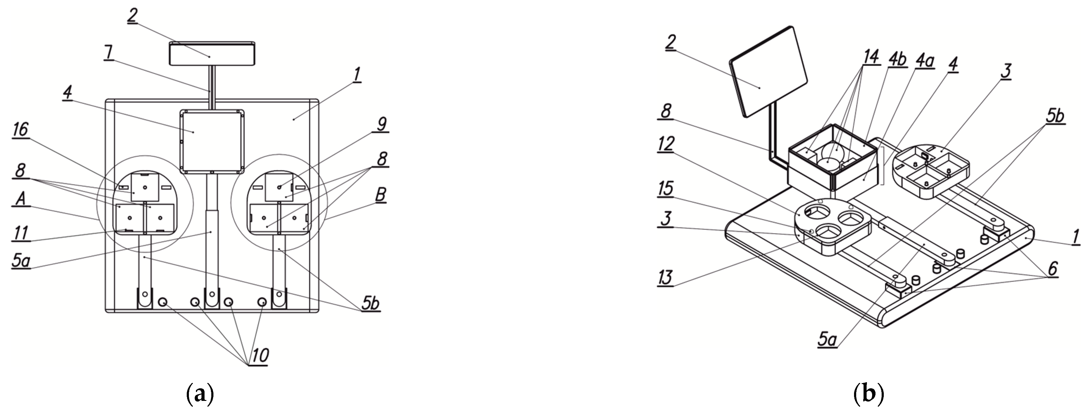
Figure 1. Rehabilitation device for the hand with its key components: (a) basic projection of the arm system, (b) isometric projection with left, right, and storage containers. 1—base, 2—display, 3—task container, 4—storage container, 4a—primary wall, 4b—secondary wall, 5a—central arm, 5b—side arm, 6—electric motor, 7—extension, 8—groove, 9—limit pressure sensor, 10—control button, 11—colour sensor, 12—attachment, 13—through-holes, 14—blocks, 15—LED, 16—socket, A—left container module, B—right container module.
Applsci 15 06613 g001
Figure 2. Characteristic stages of the device design process (FEM—Finite Element).
Applsci 15 06613 g002
Figure 3. Identification of the hand access area: (a) Basic area. (b) Model of the hand manipulation area for individuals with disabilities. AR-L and AR-R define the manipulation zones for the left and right arms, respectively, aimed at transferring objects into the left and right containers. AR-C illustrates the central manipulation area designated for retrieving objects from the storage container.
Applsci 15 06613 g003
Figure 4. Identification of characteristic dimensions: (a) length of the central arm (“1”) and the external arm (“2”), (b) determination of possible positions of the central object storage container (“1”) and the external object placement container (“2”).
Applsci 15 06613 g004
Figure 5. Hand rehabilitation device: (a) Isometric view of the model. (b) Top view, left storage unit with one of the overlays.
Applsci 15 06613 g005
Figure 6. Successive phases of the anatomical system from an open to a clenched hand (ad).
Applsci 15 06613 g006
Figure 7. Examples of training objects and their respective grasp types: (a) surface structures of spherical objects, (b) grasp of a smooth sphere, (c) grasp of objects with tubular protrusions, (d,e) grasp of block-type objects.
Applsci 15 06613 g007
Figure 8. Geometric variations of spherical objects (a) and physical object models (b).
Applsci 15 06613 g008
Figure 9. Geometric variations of cubic objects (a) and physical object models (b).
Applsci 15 06613 g009
Figure 10. Sample overlays for the mechatronic rehabilitation device.
Applsci 15 06613 g010
Figure 11. Main components of the device control system: (a) microcomputer with enclosure, (b) 10.1” colour touchscreen, (c) sensor and its electronic system for object colour identification, (d) servo drive controller.
Applsci 15 06613 g011
Figure 12. LED system and object identification sensors within the storage unit: (a) schematic diagram, (b) preliminary arrangement of storage unit components and sensors (1—sensor, 2—LED, 3—sensor for detecting the presence of an object inside the container compartment).
Applsci 15 06613 g012
Figure 13. Dialogue window of the servo controller programming application.
Applsci 15 06613 g013
Figure 14. Functional block diagram and circuitry of the upper limb rehabilitation device based on the Box and Block Test (BBT).
Applsci 15 06613 g014
Figure 15. Block diagram of the calibration algorithm for the rehabilitation training device.
Applsci 15 06613 g015
Figure 16. Basic exercise scenarios for rehabilitation of a single upper limb. Exercises within the same spatial area: (a) abduction movement of the limb, (b) parallel transfer of an object, (c) limb extension movement. Within the opposite spatial area: (d) parallel transfer of an object, (e) elbow flexion movement, (f) limb extension movement.
Applsci 15 06613 g016
Figure 17. Software and hardware testing environment.
Applsci 15 06613 g017
Figure 18. Calibration system of the upper limb rehabilitation device.
Applsci 15 06613 g018
Figure 19. Graphical interface of the upper limb rehabilitation device; windows: (a) start screen, (b) information panel of the programme.
Applsci 15 06613 g019
Figure 20. Graphical interface of the upper limb rehabilitation device; windows: (a) appraisement in three rounds, (b) sample report generated during the appraisements process.
Applsci 15 06613 g020
Figure 21. Graphical user interface of the upper limb rehabilitation device. Window: exercise difficulty selection.
Applsci 15 06613 g021
Figure 22. Graphical user interface of the upper limb rehabilitation device. Windows: (a) exercise selection at the easy level, (b) report of a completed easy-level exercise.
Applsci 15 06613 g022
Figure 23. Graphical user interface of the upper limb rehabilitation device. Windows: (a) exercise selection at the medium level, (b) report of a completed medium-level exercise.
Applsci 15 06613 g023
Figure 24. Graphical user interface of the upper limb rehabilitation device. Windows: (a) exercise selection at the hard level, (b) report of a completed hard-level exercise.
Applsci 15 06613 g024
Figure 25. Results from the appraisement module—Round 1 (storage module and both task modules aligned straight at a 0-degree angle).
Applsci 15 06613 g025
Figure 26. Results from the appraisements module—Round 2 (storage module aligned straight at a 0-degree angle, while the two task modules are tilted outward at a 30-degree angle).
Applsci 15 06613 g026
Figure 27. Results from the appraisements module—Round 3 (storage module aligned straight at a 0-degree angle, while the two task modules are tilted outward at a 60-degree angle).
Applsci 15 06613 g027
Figure 28. Results from the easy-level exercise module—Round 2.
Applsci 15 06613 g028
Figure 29. Results from the difficult-level exercise module obtained by Participant No. 1.
Applsci 15 06613 g029
Figure 30. Results from the difficult-level exercise module obtained by Participant No. 2.
Applsci 15 06613 g030
Figure 31. Results from the difficult-level exercise module obtained by Participant No. 3.
Applsci 15 06613 g031
Table 1. Geometry of spherical models used for calibration and initial testing.
Dimensions, [mm]Object Number
12345
D16270626472
D2----40
d1-5815816
d2-298-12
h-0.05 × d1,2---
e--9--
Number of
indentations/bulges
09; 12146510
Table 2. Geometry of cubes used for calibration and initial testing.
Dimensions, [mm]Object Number
1234567
A64626432323232
B32326432323232
C546434194362100
R-19-----
Disclaimer/Publisher’s Note: The statements, opinions and data contained in all publications are solely those of the individual author(s) and contributor(s) and not of MDPI and/or the editor(s). MDPI and/or the editor(s) disclaim responsibility for any injury to people or property resulting from any ideas, methods, instructions or products referred to in the content.