Article

Research on Data Transmission of Laser Sensors for Reading Ruler

1
School of Mechanical Engineering, University of Science and Technology Beijing, Beijing 100083, China
2
Taiyuan Silian Heavy Industry Co., Ltd., Taiyuan 030100, China
*
Authors to whom correspondence should be addressed.
Appl. Sci. 2025, 15(12), 6615; https://doi.org/10.3390/app15126615
Submission received: 27 March 2025 / Revised: 16 May 2025 / Accepted: 4 June 2025 / Published: 12 June 2025
(This article belongs to the Topic Micro-Mechatronic Engineering, 2nd Edition)

Abstract

A coding ruler is a device that marks position information in the fordigital signals, and a code reader is a device that decodes the signals on the coding ruler and converts them into digital signals. The code reader and encoder ruler are key devices in ensuring the positioning accuracy of coke oven locomotives and the safety of coke production. They are common information transmission and positioning detection devices that can provide accurate monitoring and information feedback for the position and speed of coke oven locomotives. Four encoding methods were studied, namely, binary encoding, Gray code encoding, shift continuous encoding, and hybrid encoding. The application scenarios and encoding characteristics of each encoding method are summarized in this paper. Hybrid encoding combines the advantages of two different encoding methods, absolute and incremental encoding, to achieve higher accuracy and stability. Hybrid coding has high positioning accuracy in the long-range coke oven tampering tracks, ensuring the accuracy and high efficiency of the tampering operation. A certain number of opposing laser sensors are installed inside the code reader to obtain 0/1 encoding and read the movement displacement of the code reader on the ruler. In order to effectively detect the swing of the coding ruler, a certain number of distance sensors are installed on both sides and on the same side of the code reader. Ruler swing is accurately detected by the sensors, which output and process corresponding signals. Timely adjustment and correction measures are taken on the production line according to the test results, which not only improves detection accuracy but also enhances the stability and reliability of the system.

1. Introduction

Coke oven locomotives are heavy machines with a large volume and significant inertia during operation that form the core equipment in coke production. Their running tracks are often several hundred meters long, which leads to extremely high requirements for accuracy and safety of operation. In the current coke production process, cachieving automatic running, precise positioning, and collaborative operation with other coke oven locomotive equipment has become a key issue in industry automation technology.
Automatic operation means that the locomotive can move steadily and quickly on the preset track, while precise positioning enables the locomotive to accurately stop at a designated operating position to ensure a smooth coking process [1].
The positioning accuracy of coke oven locomotives is closely related to the quality of coke production. During the operation of the equipment, the scale positioning device has issues with stability and accuracy. If the positioning of the code reader deviates, it leads to the inability to achieve automatic coordination among multiple devices, resulting in missed pushes of the focus [2,3]. Therefore, in-depth research on automatic positioning technology for coke oven locomotives is not only aimed at improving production efficiency but also at ensuring production quality and preventing potential risks.
Therefore, in-depth research on automatic positioning technology for coke oven locomotives is not only aimed at improving production efficiency but also at ensuring production quality and preventing potential risks.
Accurate sensor measurement and monitoring technology is crucial for ensuring product quality and improving production efficiency in modern industrial production. A small swing deviation may have a significant impact on the production process, especially in situations involving precision equipment such as coding rulers. Therefore, an efficient and reliable method is required to monitor whether the coding ruler is swinging or offset [4].

2. Encoding Rulers and Code Readers

A coding ruler is a device that marks position information in the form of digital signals so that the code reader can convert the position or motion information into digital signals [5]. A coding ruler usually consists of some marked lines or grids, which interact with the code reader through optical, magnetic, or electromagnetic methods. As shown in Figure 1, when the coding ruler moves relative to the code reader, the code reader detects the changes in these lines or grids and generates corresponding digital signals.
Using a digital code band to identify absolute position information brings remarkable convenience to the factory application of automatic positioning. Compared with the traditional measurement method, the positioning accuracy and long-term stability are greatly improved by directly reading the code band information, which effectively eliminates the possible adverse effects caused by measurement errors, time drift, temperature drift, and analog-to-digital conversion errors.
The flexible design of stainless steel and plastic compression digital code tape enables it to bend in a certain range, which is suitable not only for straight line positioning but also for curve positioning scenes. This feature greatly broadens the application scope of automatic positioning technology and enables more complex production environments to be effectively dealt with. Many types of equipment can operate simultaneously on the same bar code belt with the help of code reading and positioning technology. This not only improves the overall work efficiency but also the intelligent and efficient operation of the production line, laying a solid foundation for further improving the automation level of the factory [6].
A code reader is a device used to decode the signals on a coding ruler and convert them into digital signals. It usually includes a photoelectric sensor, magnetic sensor, or other sensors. Once the marks on the coding ruler are detected, the code reader converts them into digital signals and sends them to the computer or control system for processing.
The code reader usually contains the decoding algorithm corresponding to the coding scheme on the coding scale, and different coding methods correspond to different decoding algorithms. The accuracy and real-time performance of the positioning system can be improved by researching and designing a more universal and lightweight coding and decoding algorithm.

3. Research on Coding Ruler Data

3.1. Absolute Coding

Absolute encoders are sensors that directly output digital quantity and can directly provide accurate absolute position information. They use binary code for photoelectric conversion and can read fixed digital code matching any position of the coding ruler without calibration. This kind of encoder has excellent anti-interference ability and avoids cumulative error. Its position information can be retained even without a power supply. However, its measurement accuracy is limited by the choice of binary digits, which can be flexibly adjusted to meet accuracy requirements according to specific needs. In addition, the absolute encoder has a fixed “coding zero point”, which ensures that any other absolute position on the coding ruler is calculated based on this zero point. The absolute position data can be obtained accurately by reading the coding information of the current position [7,8].
(1)
The encoding method of natural binary code
In an absolute coding system, the core function of output code is to accurately determine an absolute position. Taking natural binary code as an example, this coding method, as a weight code, has a one-to-one correspondence with binary numbers. It is characterized by each bit having a clear size value, and these values are arranged from the highest bit to the lowest bit in the order of n power of 2, so they can be directly used for size comparison and arithmetic operation.
Due to the characteristics of natural binary coding, an absolute encoder with this coding method can be easily processed by the external controller so that the actual position reading can be obtained directly without any special conversion operation. For example, if the read natural binary code is 0111, according to the conversion rule from binary to decimal, its position value can be calculated as
1 × 2⁰ + 1 × 21 + 1 × 22 + 0 × 23 = 7
As shown in Table 1, if the natural binary code is used for position reading, it is necessary to select the required number of n bits, that is, n measurement sensing units, according to the required length of the code scale and the required measurement accuracy. The farther the positioning distance, the higher the accuracy, and the more sensing elements are needed, which is not conducive to the miniaturization and integration of the code reader. Moreover, when the binary code of two adjacent readings changes in multiple bits, errors are easily generated if multiple measurement sensing elements identify that the transmission is not synchronous.
(2)
Gray code method.
Gray code is also known as binary Gray code. Although natural binary code has the ability to directly convert digital signals into analog signals through a digital-to-analog converter, in some specific scenarios, such as when converting from decimal 3 (011) to decimal 4 (100), every bit of the binary number changes [9]. Therefore, if the encoding method of natural binary code is adopted, when the values of multiple digits simultaneously change, it is impossible to adjust the status of multiple digits synchronously, resulting in the existence of a sequence in the data refresh process. However, in the transitional stage of state change, the obtained readings may produce errors (such as 010 or 111). See Table 2 for the application of Gray code in a positioning system.
Gray code has unique and significant advantages over other coding methods. Its main advantage lies in that only one digit changes during the conversion between adjacent digits. This remarkable feature effectively reduces the logical confusion that may occur when transitioning from one state to the next and ensures the clarity and accuracy of the transition process.
Gray code has only a one-bit difference between adjacent code groups, which leads to higher reliability in the process of digital position signal conversion. Even if the displacement of the code reader changes slightly, the Gray code only changes by one digit, making it more stable than other coding methods in which two or more digits may simultaneously change in the same situation. This feature significantly reduces the possibility of errors, thus improving the performance and reliability of the whole coding system.
Assuming that the original value starts from 0, the law of Gray code generation is as follows:
  • Step 1. Change the rightmost bit value.
  • Step 2. Change the left bit of the first 1 from the right: 011.
  • Steps 3 and 4. Repeat steps 1 and 2 until all Gray codes have been generated (in other words, step (2n−1) has been taken).
Take the following as an illustrative example: suppose a 3-bit Gray code is generated, and the original value bit is 000.
  • Step 1. Change the rightmost bit value: 001.
  • Step 2. Change the left bit of the first 1 from the right: 011.
  • Step 3. Repeat step 1: 010.
  • Step 4. Repeat step 2: 110.
This process is performed until all the steps are completed. The three-digit Gray code sequence is as follows: 000, 001, 011, 010, 110, 111, 101, 100.
(3)
The conversion between binary code and Gray code
According to the comparison in Table 3, there are significant differences between Gray code and other coding methods. Specifically, whenever the data are refreshed, the digital signal read by the code reader only changes by one bit, and this change has no sequence, thus completely eliminating the possibility of code error and code mixing. This feature significantly reduces the possibility of logical confusion when transitioning from one state to the next. For example, when changing from position 7 (0100) to position 8 (1100), only the most significant bit changes from 0 to 1, and only one bit in the code group changes state [10].
In addition, Gray code is usually called cyclic binary code or reflective binary code because the difference between the maximum number and the minimum number is only limited to the difference of a one-bit state. The output signal of an absolute encoder with Gray code is a specific number sequence, not a weight code. In this coding, each bit has no fixed size, so it cannot be directly used for size comparison or arithmetic operation. At the same time, Gray code cannot directly convert signals into other types of signals.
In practical application, it is necessary to convert Gray code into natural binary code once and then read it using the upper computer to enable the corresponding control function. In the process of conversion between Gray code and natural binary code, an exclusive OR operation (the same is represented by 0, and a difference is denoted by 1) is used to replace the traditional addition and subtraction operation for binary vertical multiplication and division. This carry-less conversion method is called exclusive OR multiplication and division, and the specific algorithm is not described here.
(4)
Shift continuous encoding
So-called “continuous code shift” encoding is an encoding form composed of 0 and 1 bits, which are always kept constant. In this encoding rule, any subsequent encoding can be regarded as the result of adding “1” or “0” at the rightmost end after the preceding encoding is shifted one bit to the left. For example, if the current code is 0100110100, the code after removing the leftmost bit is 100110100. Two possible subsequent codes, namely, 1001101000 or 1001101001, can then be obtained by moving the code one bit to the left and filling the bit at the rightmost end. Although there are two options for translation compensation, the subsequent encoding of each encoding is uniquely determined in practical application.
It is worth noting that although there are two options in the process of translation compensation, in practical applications, the subsequent encoding of each encoding is uniquely determined. This is because continuous code shift encoding usually combines other encoding rules or constraints to ensure the uniqueness of the encoding. This uniqueness ensures the accuracy and reliability of encoding, enabling correct identification and parsing of encoded information in digital processing and communication processes.
In shift continuous encoding with n bits, there are n−1 consecutive and identical digits between two adjacent encoding. An overlapping sequence of displaced continuous encoding can be formed if the adjacent codes in a displaced continuous encoding sequence are overlapped according to their identical features. As shown in Table 4, the sequence is the overlapping sequence of a displaced continuous code with a bit length of 4. In this sequence, each 4-bit adjacent 0/1 digital combination constitutes a unique code. A coding sequence closely related to the digital position can be obtained if the number at any position is taken as the starting point and forms a code together with the three numbers on the right [11].

3.2. Hybrid Coding

In the field of digital encoding, traditional encoding methods such as binary encoding and Gray code encoding and innovations such as continuous shift encoding have limitations to some extent. Under the condition of limited bits, these coding modes can complete relatively few positioning coding tasks.
A hybrid encoding method is proposed in order to overcome the limitations of these traditional encoding methods. The core idea of this encoding method is to generate a large number of different codewords by using random sequences. Under the condition of finite bits, the combination of random sequence encoding and displacement continuous encoding increases location encoding so as to meet wider application requirements [10].
Specifically, hybrid encoding combines the advantages of two different encoding modes, absolute and incremental encoding, to achieve higher accuracy and stability, and its working principle is that the position and speed are accurately monitored and fed back through the combined operation of the two encoding modes.
As shown in Table 5, two coding modes are combined, one for absolute position and the other for relative position.
In practical engineering applications, due to significant vibrations in the working environment, the positioning accuracy of hybrid coding is ±2 mm, and the scale installation track is 300 m. The positioning accuracy of binary coding is ±3 mm.
This encoding method based on a random sequence has many advantages in practical application. First, it can make full use of limited bit resources to generate more location codes, thus improving coding efficiency and flexibility. Secondly, due to the random sequence, the generated codeword has a better anti-jamming capability and can effectively resist the impact of noise and interference on the coding performance. This method also has better security because the generation and conversion process of the random sequence can be designed to be very complex and difficult to predict.
Determining sequences are sequences that can be predetermined and repeatable. A pseudo-random sequence is a sequence that cannot be determined in advance, but its generation process can be repeated; sequences that are neither predetermined nor repeatable are called random sequences.
An m sequence, also known as a maximum periodic feedback shift register sequence, is a pseudo-random binary sequence widely used in various fields [12]. It can be applied to spread spectrum communication to improve anti-jamming capability and the confidentiality of communication and achieve efficient spectrum utilization and signal separation in CDMA technology in satellite communication. In addition, in terms of digital data processing, an m sequence can be used for encryption and scrambling to ensure data security, synchronization, and bit error rate measurement to improve the accuracy and reliability of data transmission. These applications fully demonstrate the superior performance and wide application prospects of m sequences in the communication field.
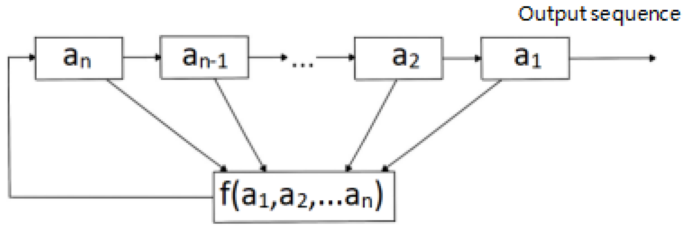
An n-level feedback shift register on GF (2) consists of n binary memories and a feedback function f (a1, a2, …, an), as shown in Figure 2. There is a total of n registers (a1, a2, …, an). Each register is a 0/1 binary storage unit, called the stage of feedback shift register. There is a total of 2n possible states. From left to right, there is a feedback f, its input is a1~an, its calculation result is an output of an + 1, and the feedback result an + 1 is output to an. At the same time, each level of memory ai transmits its contents to the next level ai−1, and f (a1, a2, …, an) is calculated as the contents of an at the next time according to the state of memory at that time.
We can precisely encode a specific absolute position by placing a binary marker based on the m-sequence on the encoder scale. When the readers read these binary markers one by one in a given order from the starting point, the coding sequence they form in the memory presents a unique feature. With this unique location code value as the search address, we can quickly find and obtain the detailed location information of each location in the pre-built database so as to effectively enable the function of ranging transmission.

3.3. Coder Bar Grid Description

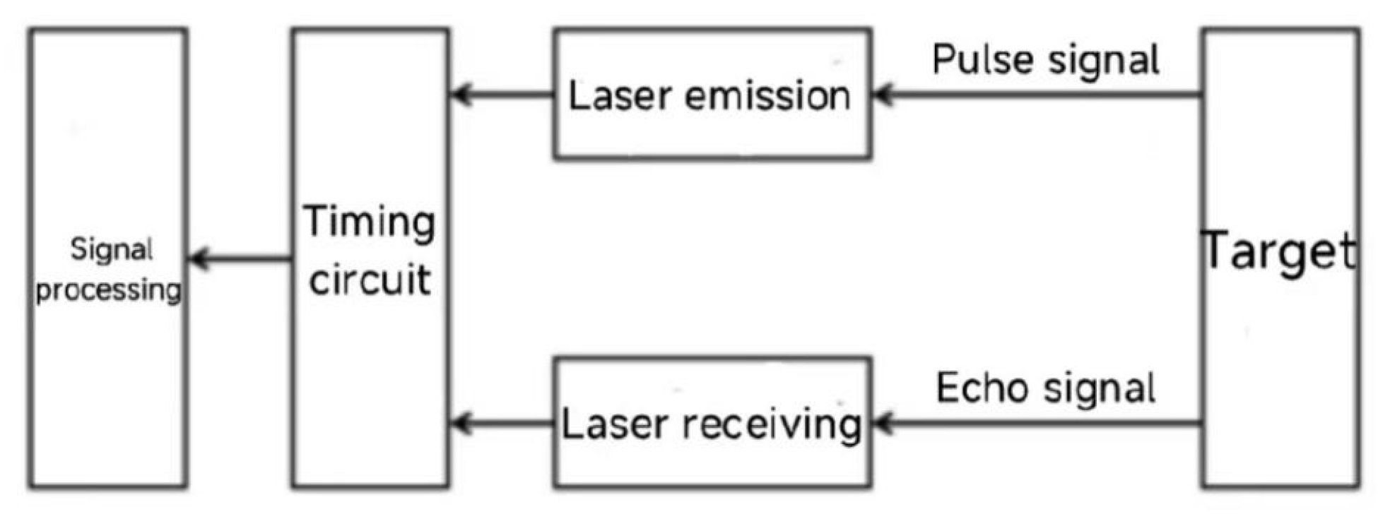
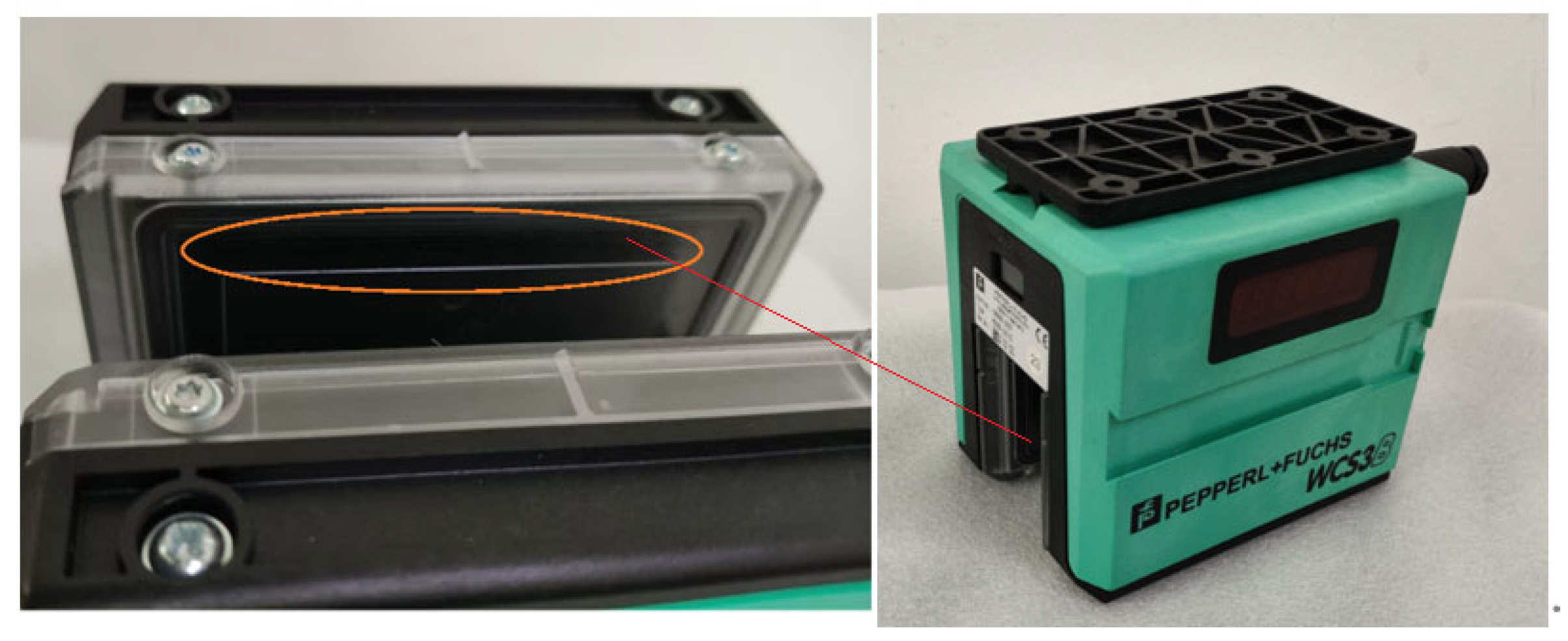
First, an understanding of the basic composition of the reader is required. Inside the U-shaped reading wharf, a laser transmitter is installed on one side, and a laser receiver is installed on the other side [13,14,15]. The laser transmitter emits a steady beam, which travels through a specific path and is finally received by the corresponding laser receiver. When the receiver successfully receives the beam, it converts this signal into a digital signal to read the data.
When the reader is installed on the ruler track, it begins to efficiently read data. A key element in this process is the light-tight encoder. Different areas on the encoder scale have different effects on the beam. When the beam from the laser transmitter is blocked by one side of the encoder, the laser receiver cannot receive the optical signal, and the digital signal “0” is output.
With the relative displacement of the code reader on the ruler track, the correlative laser sensor continuously passes through the holes on the ruler. The beam can pass normally when the sensor passes through these holes. At this time, the laser receiver receives the optical signal and outputs the digital signal “1”.
We follow certain rules in order to accurately depict the encoder. In encoding, “1” corresponds to the hollow part and “0” to the solid part on the ruler. In this way, the solid and hollow parts on the encoder ruler constitute a unique encoding sequence, as shown in Table 6. In this example, the code “11100100101011” corresponds to a series of solid and hollow parts on the encoder scale.
It is worth noting that the data reading method of this laser sensor has many advantages. First, it has very high reading accuracy and can meet the needs of most application scenarios. Second, because it uses a laser as the signal transmission medium, it has a strong anti-interference ability and can operate stably in a harsh industrial environment.

4. Sensor Technology and Code Reading Error Analysis

The purpose of laser positioning technology, as a form of high-precision distance measurement, is to use a precise timing system to measure the time difference of laser transmission so as to accurately determine the distance between a moving subject and the measurement target. In practical applications, laser positioning technology is usually applied to one end of the track on mobile rail locomotives with a fixed laser rangefinder installed.
Laser reflectors that can move with the locomotive can be installed to ensure a stable horizontal linear relationship between the two. Collisional laser sensors and laser ranging sensors are commonly used sensors in code readers.

4.1. Opposed Laser Sensor

A laser sensor is mainly composed of a laser transmitter, receiver, and signal processor. Its working principle is based on the photoelectric effect and the transmission of light beams. When the laser transmitter emits a laser beam, the light beam travels along a specific path. If there is no object blocking the beam path, the receiver receives the complete laser beam and generates the corresponding electrical signal.
Once an object enters the beam path and blocks the beam, the laser intensity received by the receiver is attenuated or completely lost depending on the material that blocks the object, causing the output electrical signal to change.
The existence, location, distance, and other information of an object can be calculated by analyzing the changes in electrical signals through a signal processor [16].
Laser sensors are less sensitive to lighting and color changes in the working environment and can operate normally under various lighting conditions.
Paired laser sensors have strong anti-interference ability, can perform sub-centimeter level transmission within a few milliseconds, and have high measurement accuracy. Therefore, paired laser sensors are widely used in the fields of object detection, positioning, and counting on automated production lines.

4.2. Laser Ranging Sensor

A laser ranging sensor also has two main parts, a laser transmitter and a photoelectric receiver, but the transmitter and receiver of the ranging sensor are mounted on the same side as the correlative laser sensor, and the laser transmitter emits a laser beam that strikes the target surface and is reflected. The photodetector receives the reflected light signal and calculates the distance of the target object through measurement, which gives the laser sensor extremely high measurement accuracy and stability.
(1)
Pulse laser ranging
The pulse method is also known as the laser echo method. Its core principle is to use the flying time difference of the laser for accurate ranging. This method makes full use of the characteristics of the laser pulse; that is, the pulse duration is very short, and the energy is relatively concentrated in time so as to achieve instantaneous, high-power output. In the case of a cooperative target, the pulse method can be used to perform accurate, long-distance measurements. Even in a relatively close range (several thousand meters), this method can lead to effective ranging in a low-accuracy scenario even if there is no cooperative target [17].
The operating principle of pulsed laser ranging, as shown in Figure 3, is as follows: The laser emission system emits a pulse laser with a very short duration, which is reflected by the target object after passing through the distance L to be measured. The reflected pulse laser signal is then captured by a photodetector in the laser receiving system. The time difference t between the laser emission and the arrival of the echo signal is accurately calculated by the time interval circuit, and the accurate distance L between the target object and the emission source can be calculated according to the principle of constant light velocity.
(2)
Phase laser ranging
The phase-type laser range finder uses the frequency of the radio wave band to conduct amplitude modulation on the laser beam and measure the phase delay generated by the modulation light back and forth through the measuring line. The distance represented by the phase delay is then converted according to the wavelength of the modulation light [18]. Indirect methods are used to determine the time required for light to travel back and forth through the measuring line. If the angle frequency of modulation light is ω and the phase delay generated by one round trip on the distance to be measured D is ϕ , the time t corresponding to one round trip can be expressed as follows:
t = ϕ ω
If the propagation velocity of light in the atmosphere is c
D = c t 2
Substituting Equation (1) into Equation (2), the distance D can be expressed as follows:
D = c t 2 = c ϕ 2 ω = c 4 π f ( N π + Δ N ) = c 4 f ( N + Δ N )
where ϕ is the total phase delay generated by the signal round-trip survey line at one time; the angular frequency of the modulation signal ω = 2 π f ; N is the number of modulation half-wavelengths included in the measuring line; ∆ ϕ is the phase delay less than π generated once by the signal round-trip measuring line; and ∆ N is the fractional part of the modulation wave of less than half a wavelength included in the measuring line, ∆ N = ϕ / ω .
Under the given modulation and standard atmospheric conditions, the frequency c / ( 4 π f ) is a constant. At this time, the measurement of distance becomes the measurement of the number of half-wavelengths included in the measuring line and the measurement of the decimal part less than half-wavelength, i.e., measuring N or ϕ . The measurement of ϕ has reached a very high level of accuracy due to the development of modern precision machining and radio phase measurement technology.
In order to measure the phase angle ϕ that is less than π, different methods can be used. Delay phase measurement and digital phase measurement are generally the most widely used methods. At present, the digital phase measurement principle is adopted for short-range laser rangefinders to obtain ϕ .

4.3. Detection of Yardstick Swing

The reader slides on the ruler track with the goal of accurate positioning. In this process, the transmission of location data is very important and is comparable to an invisible link, which closely connects the reader with the encoder. As shown in Figure 4, The Y-axis is the horizontal axis parallel to the guide rail, and the Z-axis is the vertical axis perpendicular to the guide rail. The angle α is the swing angle of the encoder deviating from the guide rail. when the caliper track encounters strong vibration or a large swing, the laser spot that is stably hit on the target receiving area may be offset. Once the laser spot deviates from the predetermined receiving area, the reflected light that the receiver can capture is weakened or even completely blocked in extreme cases. This seemingly small change may have a profound impact on the measurement signal, and any small interference may cause fluctuations in the measurement data.
When the measurement signal changes due to the offset of the light spot, the measurement accuracy of the code reader is affected, which may be reflected in the instability of the reading, the increase in the error, or even the obvious error of the positioning. This error can be fatal on the production line because it can trigger a series of chain reactions that eventually lead to a reduction in product quality or production efficiency [19,20].
The accuracy and stability of ranging technology in the industrial production process is very important to ensuring quality and efficiency. If the yardstick swings excessively, the ranging result is inaccurate. A phase laser ranging sensor is required to accurately detect and judge the shaking of the yardstick. In the process of yardstick swinging, the sensor is used to monitor the shaking of the yardstick in real time. When the yardstick swinging amplitude exceeds a certain threshold, the sensor sends a signal denoting necessary adjustment or intervention.
(1)
Detection principle
Under normal working conditions, the reader is firmly fixed on the yardstick rail to ensure its stable operation and accurate reading. The common U-shaped code reader is designed so that two detection surfaces are parallel to the encoder. This parallel state is essential to ensure the accuracy of the reading. The distance from each point on the encoder scale to both sides of the reading wharf shall be equal according to the definition of plane parallelism. This means that the reader can obtain information with the same accuracy regardless of which point on the encoder scale is read.
However, in practice, the encoder may swing due to various factors. When the encoder scale swings, the two detection surfaces of the U-shaped reader are no longer parallel to the encoder scale. This non-parallel state causes a disparity in the distance from some points to both sides of the reading wharf, thus affecting the accurate reading of the information on the encoder.
In order to detect whether the encoder is in a state with large error, such as shaking, we only need to detect whether the distance difference between two points on the laser emitting surface of the reader and the encoder exceeds a certain range. An excessive distance between these two points and the encoder indicates that the encoder is shaking, and the reading result of the reader may be seriously affected.
(2)
Sensor Layout
The U-shaped code reader, as shown in Figure 5, is accurately configured on an encoder scale to perform its code reading function. The reader can automatically detect and record a new position value every 0.8 mm. The operation process of the reader does not require a set reference point, and its response is fast. It only requires 1 ms to complete the calculation of the position value. The code reading speed can reach 12.5 m/s, and position values can be determined accurately in real time. The reader is also stable and reliable and is not disturbed by ambient temperature fluctuation. It supports RS-485 and SSI interfaces, which can directly and efficiently transmit the location data to the controller to enable seamless information docking. The reader of the WCS position coding system is firmly installed on the conveyor body, and the coding ruler is installed on the guide rail pad in parallel so as to ensure real-time and accurate code reading and positioning during operation [10,21,22].
Inside the U-shaped reading wharf, a laser transmitter is installed on one side, and a laser receiver is installed on the other side. The beam emitted by the transmitter is received by the corresponding receiver and converted into a digital signal. When the code reader is installed on the ruler track, the lightproof encoder blocks the beam emitted from one side, and the receiver cannot receive the optical signal, so the digital signal “0” is output. With the relative displacement of the code reader on the coding ruler track, the correlative laser sensor passes through the coding grid carved on the coding ruler, and the beam normally receives and outputs the digital signal “1”.
There are 24 laser sensors installed in close arrangement inside the reading wharf. A 24-bit 0/1 code can be obtained by recording 24 0/1 digital signals. With the movement of the code reader on the yardstick, the read code changes accordingly. Then, the corresponding decoding algorithm obtains the specific displacement of the current position relative to the zero point according to the coding principle.
One end of the yardstick track is fixed, and deviations of two or more degrees of freedom indicate shaking.
As shown in Figure 6, only three ranging sensors are installed at the corresponding positions on both sides of the reader and at the same horizontal position on the same side in order to effectively detect whether the yardstick swings. This design not only improves the detection accuracy but also enhances the stability and reliability of the system.
Once the installation is completed and successfully commissioned, these ranging sensors begin to function. The sensor can quickly sense yardstick swing and output the corresponding signal. We can accurately analyze the swing of the decoding ruler by collecting and processing these signals so as to take corresponding measures for adjustment and correction.
The laser sensor detects the oscillation of the code ruler, with a dynamic minimum detection threshold of ±3 mm, and the reader moves along the code ruler at a speed of 1.5 m per second. The impact vibration from the consolidation machine is significant and the operating environment is harsh. The minimum amplitude sensitivity detected by the system is less than or equal to 20%.
In addition, multi-point monitoring of the yardstick can be achieved by installing multiple ranging sensors. This can not only improve the accuracy and reliability of the detection but also help us to more comprehensively analyze the swing of the decoding ruler. It can be determined whether the yardstick swings evenly and whether there are abnormal points by comparing the sensor data at different positions.

5. Engineering Experimental Testing

The engineering application site is shown in Figure 7. The length of the scale track is 300 m. Continuous production data for 150 h. Sampling period: 10 ms. In the experimental tests, the key performance indicators of two-dimensional coding and hybrid coding are shown in Table 7. Dynamic performance analysis as shown in Table 8. Scanning recognition efficiency (average of 1500 tests), Performance comparison test data as shown in Table 9.

6. Conclusions

Binary encoding is an encoding mode based on 0 and 1 bits that is widely used in computer science, communication, and other fields. It has the advantages of simplicity, easy implementation, and high storage and transmission efficiency. However, it may produce large errors when processing continuously changing signals. In addition, the anti-jamming capability of binary code is relatively weak. The decoding process may encounter problems once disturbed.
Gray code is a special binary encoding method in which there is only a one-bit difference between two adjacent values. This characteristic increases the stability of Gray code in the process of converting analog signals to digital signals. At the same time, Gray code also has good anti-interference capability, which can reduce decoding errors to some extent. The disadvantages of Gray code are that its encoding process is relatively complex, and its storage and transmission efficiency is slightly lower than that of binary encoding.
Shift continuous encoding is a method of converting analog signals into digital signals. This method adapts to the change in signal by continuously changing the number of encoded bits. This coding mode can continuously represent changing signals more accurately and reduce errors. At the same time, displacement continuous encoding has high flexibility and adaptability and can be applied to various complex scenes. However, it is difficult to implement, requires specialized hardware and algorithms, and may generate large delays.
Under the condition of finite bits, the hybrid encoding method combines random sequence encoding and shift continuous encoding to increase location encoding so as to meet wider application requirements. Hybrid encoding combines the advantages of the absolute encoder and the incremental encoder to achieve higher accuracy and stability. Its working principle is to provide accurate monitoring and feedback of the position and speed through the combined operation of the two encoding modes. Positioning accuracy improved by 33.3%. Error tolerance improved by 42%, Response time improved by 42%.
In order to monitor the swing deviation of the encoder in real time, we can install a phase laser ranging sensor on the code reader. This sensor can emit a laser beam, receive reflected optical signals, and accurately calculate the distance between the reader and the encoder by measuring the return time or phase change of the laser beam. If the encoder scale swings, this distance change is captured by the sensor and converted into the corresponding electrical signal output. We can obtain the swing offset of the encoder by analyzing and processing the electrical signal output by the sensor.
Phase laser ranging sensors offer several other advantages, making them ideal for monitoring the oscillation offset of encoder scales. First, they have very high measurement accuracy and stability, which can ensure the accuracy of the monitoring results. Second, they can operate normally in various harsh industrial environments, such as high-temperature, high-humidity, and dust environments, with high adaptability and reliability. Finally, they can be integrated and linked with other automation equipment to enable more intelligent monitoring and control.
In conclusion, installing phase laser ranging sensors on the code reader is an efficient and reliable method of monitoring encoder scale swing. This method can not only improve product quality and production efficiency but also reduce production costs and maintenance costs and bring greater economic and social benefits to enterprises.

7. Patents

ZL 2024 2 0442840.2 The utility model has been obtained, and the invention patent is currently pending approval.

Author Contributions

Conceptualization, R.W.; methodology, C.L. and C.S.; software, X.L. and D.Z.; validation, B.F. and C.L.; formal analysis, J.Z., B.F. and C.L.; investigation, B.F.; resources, R.W.; data curation, B.F., J.Z. and D.Z.; writing—original draft preparation, B.F.; J.Z., X.L. and D.Z.; writing—review and editing, B.F. and J.Z.; visualization, X.L.; supervision, B.F.; project administration, C.S.; funding acquisition, B.F., J.Z., X.L., C.S. and D.Z. All authors have read and agreed to the published version of the manuscript.

Funding

Other longitudinal projects of Beijing University of Science and Technology, project number TYKJ2023001.

Data Availability Statement

The original contributions presented in the study are included in the article.

Conflicts of Interest

Author Rong Wang and Chen Lei were employed by the company Taiyuan Silian Heavy Industry Co., Ltd. The remaining authors declare that the research was conducted in the absence of any commercial or financial relationships that could be construed as a potential conflict of interest.

References

  1. Guan, Z. Design and Implementation of Automatic Positioning System for Coke Oven Locomotives. Master’s Thesis, Hunan Normal University, Changsha, China, 5 June 2024. [Google Scholar]
  2. Xue, H. Research on Key Technologies of Absolute Position Measurement Sensor. Master’s Thesis, Hefei University of Technology, Hefei, China, 2017. [Google Scholar]
  3. Zhang, B. The Design of Rail Wheel Identification System Based on RFID. Master’s Thesis, Qingdao University, Qingdao, China, 2021. [Google Scholar] [CrossRef]
  4. Huang, M. Research on Self-Calibration Method for Spliced Linear Grating Displacement Sensors. Master’s Thesis, Chongqing University of Technology, Chongqing, China, 2024. [Google Scholar]
  5. Dai, M.; Feng, Y. Research and design of centralized control system for long rail group crane. J. Zhengzhou Railw. Vocat. Tech. Coll. 2012, 24, 19–20. [Google Scholar]
  6. Dai, M.; Jiang, X.; An, W. Application of Gray Bus in Centralized Control System of Long Rail Group Hoisting. Railw. Stand. Des. 2012, 11, 28–31. [Google Scholar] [CrossRef]
  7. Xu, N. Absolute encoder realizes angle measurement of port machinery through PLC. Port Handl. 2007, 27–28. [Google Scholar]
  8. Feng, Y.; Cheng, J. Design of absolute encoder coding system. Shanxi Electron. Technol. 2008, 43–44. [Google Scholar]
  9. Duan, B. Gray Code and Its Transformation Application. Foreign Build. Mater. Sci. Technol. 2005, 68–69. [Google Scholar]
  10. Tao, L. Research on Data Transmission of Laser Sensor with Code Reader. Diploma Thesis, University of Science and Technology Beijing, Beijing, China, 17 June 2024. [Google Scholar]
  11. Zheng, H.; Lin, C. Research and application of displacement continuous coding principle. J. Metrol. 2003, 24, 29–31+39. [Google Scholar]
  12. Qiu, C.; Zhu, H. Train positioning technology based on absolute position coding. J. Railw. 2007, 29, 118–122. [Google Scholar]
  13. Li, J. Fast and accurate positioning of positioning vehicle by laser-targeted photoelectric sensor. Waterw. Eng. 2015, 50–54. [Google Scholar] [CrossRef]
  14. Kawauchi, K.; Miyaki, T.; Rekimoto, J. Directional Beaconing: A Robust WiFi Positioning Method Using Angle-of-Emission Information. In Proceedings of the Location and Context Awareness 4th International Symposium, LoCA 2009, Tokyo, Japan, 7–8 May 2009. [Google Scholar]
  15. Chehri, A.; Fortier, P.; Martin, P. Tardif UWB-based sensor networks for localization in mining environments. Ad HocNetworks 2009, 7, 987–1000. [Google Scholar]
  16. Li, Q. Research on Absolute Displacement Detection Method Based on Maximum Length Sequence Coding. Master’s Thesis, Nanjing University of Aeronautics and Astronautics, Nanjing, China, 2017. [Google Scholar]
  17. Zhao, H. Working principle of laser ranging sensor and its application in automobile production equipment. The 15th Henan Province Automotive Engineering Technology Academic Seminar. Henanluohe 2018, 235–237. [Google Scholar]
  18. Gao, B. Research on Denoising of Phase-based Laser Ranging Signal Based on Wavelet Transform. Master’s Thesis, Nanchang University, Nanchang, China, 2023. [Google Scholar]
  19. He, X.; Cao, Q.; Fan, K. Research and design of underground mine car positioning monitoring system based on ZigBee. Met. Mine 2015, 44, 127–132. [Google Scholar]
  20. Alejandre, I.; Artes, M. Thermal non-linear behaviour in optical linear encoders. Int. J. Mach. Tools Manuf. 2006, 46, 1319–1325. [Google Scholar] [CrossRef]
  21. Alejandre, I.; Artés, M. Method for the evaluation of optical encoders performance under vibration. Precis. Eng. 2007, 31, 114–121. [Google Scholar] [CrossRef]
  22. Ye, B.; Yan, W.; Zhu, J. Positioning system design of FMS transport aircraft. Intern. Combust. Engine Accessories 2018, 6–7. [Google Scholar] [CrossRef]
Figure 1. Working schematic diagram of code reader and coding ruler.
Applsci 15 06615 g001
Figure 2. n—level feedback shift register.
Applsci 15 06615 g002
Figure 3. Schematic diagram of pulse laser ranging principle.
Applsci 15 06615 g003
Figure 4. Oscillation of yardstick.
Applsci 15 06615 g004
Figure 5. Code reader structure.
Applsci 15 06615 g005
Figure 6. Sensor layout.
Applsci 15 06615 g006
Figure 7. The engineering application site.
Applsci 15 06615 g007
Table 1. Application of Binary Code in Positioning System.
bit00001111
0001101100011011
Sensing element 100001111
Sensing element 200110011
Sensing element 301010101
01010101
Table 2. Application of Gray Code in Positioning System.
Gray code00000101111110
0110011
Sensing element 10001111
Sensing element 20011110
Sensing element 30110011
Table 3. Correspondence Between Four-Bit Binary code and Gray Code.
Decimal ValueBinary ValueGray Code
000000000
100010001
200100011
300110010
401000110
501010111
601100101
701110100
810001100
910011101
1010101111
1110111110
1211001010
1311011011
1411101001
1511111000
Table 4. Continuous Coding of Displacement.
0000100110101111
0000 (0)1001 (4)1010 (8)1111 (12)
0001 (1)0011 (5)0101 (9)
0010 (2)0110 (6)1011 (10)
0100 (3)1101 (7)0111 (11)
Table 5. Mixed Coding Diagram.
01000000110000111100110
0 0 0 0 1 0 0 1 1 0 1 0
1 0 0 0 1 0 0 1 1 0 1
Table 6. Characterization of Encoder.
Encoding sequence00011011010100
Coding ruler11100100101011
11100100101011
11100100101011
11100100101011
Table 7. Key Parameter Indicators of the System.
IndicatorTraditionalHybridImprovement
CodingCodingRate
Positioning Accuracy (mm)±3±233.3%
Repeat Positioning Accuracy (mm)±1.6±0.850%
Response Time (ms)452837.8%
Failure Rate (times/thousand hours)6.42.265.6%
Table 8. Dynamic Performance Analysis.
Speed (m/s)Traditional Coding Error (mm)Hybrid Coding Error (mm)
0.50.80.18
1.01.80.29
1.52.70.70
2.03.80.69
Remarks: Tracking error under the condition of acceleration 1.5 m/s2.
Table 9. Performance Comparison Test Data.
Average recognition time (ms)350 ± 25195 ± 1744.3%
Low light success rate65%89%24%
Partial Occlusion Tolerance Rate34%76%42%
Maximum recognition distance (m)1.22.4100%
Disclaimer/Publisher’s Note: The statements, opinions and data contained in all publications are solely those of the individual author(s) and contributor(s) and not of MDPI and/or the editor(s). MDPI and/or the editor(s) disclaim responsibility for any injury to people or property resulting from any ideas, methods, instructions or products referred to in the content.

