Article

Structural Health Monitoring of Aerial Vehicles Using Guided Electromagnetic Waves in K-Band: Initial Damage Detection Results from Drone Flight Testing

1
Department of Mechanical Engineering, University of Siegen, 57076 Siegen, Germany
2
Department of Physics, Goethe University Frankfurt, 60438 Frankfurt, Germany
3
IMST GmbH, 47475 Kamp-Lintfort, Germany
4
Escuela Técnica Superior de Ingeniería Aeronáutica y del Espacio, Universidad Politécnica de Madrid, 28040 Madrid, Spain
5
Department of Industrial Engineering, University of Naples Federico II, 80125 Naples, Italy
*
Author to whom correspondence should be addressed.
Appl. Sci. 2025, 15(12), 6478; https://doi.org/10.3390/app15126478
Submission received: 26 March 2025 / Revised: 16 May 2025 / Accepted: 4 June 2025 / Published: 9 June 2025
(This article belongs to the Special Issue Novel Approaches for Fault Diagnostics of Machine Elements)

Abstract

This paper introduces a novel structural health monitoring (SHM) approach based on guided electromagnetic waves propagating in a dielectric waveguide in the frequency range from 23.5 to 26 GHz. This approach enables the detection of structural damage based on the analysis of radar signals. This paper presents the performance of the methodology through an experimental case study considering an autonomous heavy lift drone where the whole SHM system is integrated onboard. The whole data acquisition pipeline is described, and damage detection results based on a damage indicator approach are presented and discussed. Finally, this work proves the ability of guided electromagnetic wave technology to be used in flying aerial vehicles. The methodology can be applied to other aircraft structures and application cases in the future.

1. Introduction

The importance of drones for private and industrial purposes has grown rapidly in recent years. In Europe alone, it is estimated that a total of 400,000 commercial drones and around 7 million drones for hobby purposes will be registered in the next 30 years. For reasons of economic efficiency, commercial use in particular is focusing on highly automated operation of drones—with minimal use of pilots and even completely autonomous in the long term. Such unmanned aerial vehicles (UAVs) can be used in the context of traffic/logistics, forestry and agriculture, alarm and warning systems, pipeline monitoring, shipping, etc. A heavy lift drone is considered in this work as a platform carrying the whole structural health monitoring (SHM) system.
In the literature, several monitoring approaches have been proposed to improve the flight safety of UAVs. One example is presented in [1], where structural vibrations are measured with accelerometers for undamaged and damaged drones. The computation and analysis of a damage index (DI) is performed onboard and in real time. A related study that also processed vibration signals was presented by Ghazali and Rahiman in [2] employing artificial intelligence methods. As an alternative, it is also possible to process audio signals for the analysis of structural drone conditions, as demonstrated in [3,4].
Recently, guided electromagnetic waves in K-band have shown excellent damage detection properties thanks to their sensitivity to waveguide properties [5]. The performance thereof is improved by the inherent absence of parasitic effects from secondary reflections of the structure and independence upon any surface contaminants. The most common nondestructive testing approach relies on the dielectric properties of the monitored structure. However, during the last decade, different approaches have been introduced, including a jointed electromagnetic waveguide [6] and microwave leakage monitoring [7]. The former one exploits a specific supplementary waveguide confining the electromagnetic wave across the structure. The second approach exploits the dielectric properties of a cavity to establish a proper waveguide when electromagnetic wave propagation is shielded by the boundaries. This last approach has been adopted for pipe inspection to detect wall thinning [8], cracks [9,10,11], and slits [12], achieving a detection range of 19–26.5 m for multiple pipe diameters [13].
The methods’ applicability to side incident inspection [14], bent pipe inspection [15], and multi-flaw detection [16] has also been verified. Also, the probability of detection has been established to assess reliability [17]. However, all these examples have been tested in laboratory facilities, employing high-fidelity devices and equipment. In this paper, the authors show for the first time an in situ application attempt, where the system is integrated onboard an autonomous heavy lift drone to manage the data acquisition pipeline in flight.

2. Experimental Setup

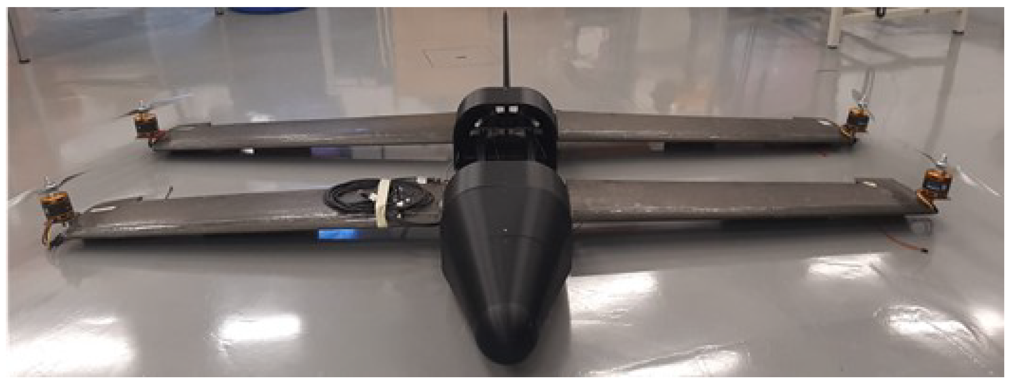
2.1. Autonomous Heavy Lift Drone

The LIBIS is an electrically powered UAV designed for versatile aerial operations (Figure 1). This UAV has a maximum takeoff weight of 25 kg and a wingspan of 2 m, achieved through its unique tandem wing configuration. Each semi-wing is equipped with a brushless motor, enabling the UAV to perform vertical takeoffs and landings by operating as a rotary-wing aircraft.
The UAV is powered by four batteries positioned at its center of mass. Although the tip motors enable fixed-point flight, this mode is highly inefficient and leads to rapid battery depletion. To extend its flight range, the LIBIS switches to a fixed-wing configuration, where a tail motor provides forward thrust, allowing for longer flight durations on a single charge.
The UAV is controlled by a Pixhawk flight controller, which incorporates GPS, compass, and accelerometer–gyroscope modules. This flight controller is capable of managing the five motors, actuators, and batteries without encountering pin limitations. Additionally, it enables autonomous flight operations, eliminating the need for manual piloting.
The LIBIS structure is composed of three primary materials. Load-bearing components, including the wings and central fuselage box, are constructed from carbon fiber and aluminum. The central box, made from extruded aluminum profiles, allows for the easy integration of experimental equipment. Non-load-bearing components are 3D printed from PLA and PETG filament, providing flexibility to modify their geometry and accommodate various payloads. In this experiment, the upper fuselage section was adapted to house the device under test (DUT).

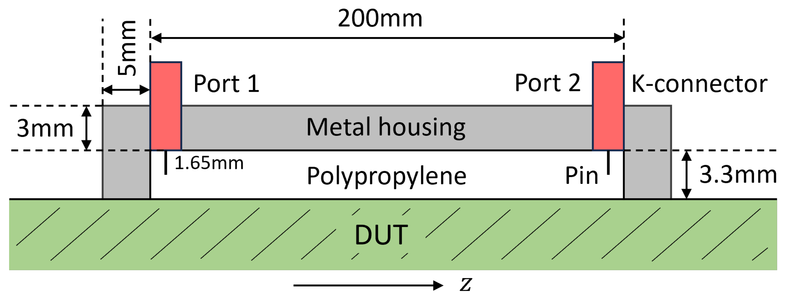
2.2. Design, Realization, and Characterization of the Dielectric Waveguide

Electromagnetic waves (EWs) can propagate in 3D open space or in a volume constrained by metallic boundary conditions. Metallic boundary conditions cause electromagnetic fields to disappear at the edges, resulting in complete reflection. EWs propagating in so-called waveguides are denoted as guided EWs. Resonators are a special case in which metallic boundary conditions exist in all three spatial dimensions. Cavities indicate that the dielectric consists of a gas or vacuum. On the other hand, dielectric resonators can also be filled by a dielectric medium [18]. Concerning electrodynamics, solving Maxwell’s equations results in characteristic resonant frequencies that can be calculated analytically for plane-parallel, rectangular, and cylindrical waveguides [19]. For other cross-sections and non-metallic boundary conditions, such as those present in omega stringers, only numerical calculations are possible [7].
For the proof of concept in this work, a rectangular dielectric resonator was filled with polypropylene with dimensions of 200 mm × 100 mm × 3.3 mm, as shown schematically in Figure 2. A numerical model in CST Microwave Studio is depicted in Figure 3a. Four scattering parameters with the two-port setup can be measured when electromagnetic energy is coupled into and out of the waveguide through the K-connectors. The metallic housing made of aluminum is used to fulfill the three-dimensional metallic boundary conditions for the lowest possible transmission loss.
In a previous study, Rao et al. [18] used this waveguide under laboratory conditions with a vector network analyzer (VNA) for ultra-wideband stimulation from 20 GHz to 40 GHz. To set the resonant frequency to the center frequency of 30 GHz, a thickness of 3.3 mm was determined for the polypropylene matrix. However, the VNA cannot be used for in situ demonstration due to its large dimension and significant weight.
Together with an aluminum test plate, which is shown in Figure 3b, the waveguide is completed. The test plate is screwed to the substrate and consists of seven holes (numbered consecutively) with diameters ranging from 2 mm to 8 mm, which can be closed with screws. Starting with the reference state, which represents the intact structure of the DUT, the screws are unscrewed one after the other in order to measure structural changes systematically.
Preliminary numerical and experimental results with the VNA from 23.5 GHz to 26 GHz are shown in Figure 4. S 11 stands for the reflected signal at port 1 and S 21 for the transmitted signal from port 1 to port 2. Due to the symmetry of the waveguide, S 12 and S 22 are similar. More transmission is given with a higher frequency up to the excitation of the first mode at 30 GHz. The trends of simulated and experimental S 11 are comparable.
The proposed device benefits from the metallic housing so that microwave radiation remains inside the cavity. This means that the immunity and susceptibility of the UAV is not affected [20]. The same shielding protects the device from electromagnetic interference from the outside, for example, coming from criminals and the environment [21]. The proposed sensing method can be considered an alternative to the widely used comparative vacuum monitoring approach reported in [22], making the method attractive for the continuous monitoring of various structural defects such as cracks. However, the orientation of cracks relative to the angle of incidents must be taken into account, as demonstrated through parametric simulations in [6]. In contrast to global monitoring approaches, using accelerometers and strain gauges [23], the proposed method is a local damage detection technique that is able to identify small damage sizes in the order of only 1 to 2 mm [6]. In order to separate the effects from multiple holes, a blind source separation technique can be used [24].

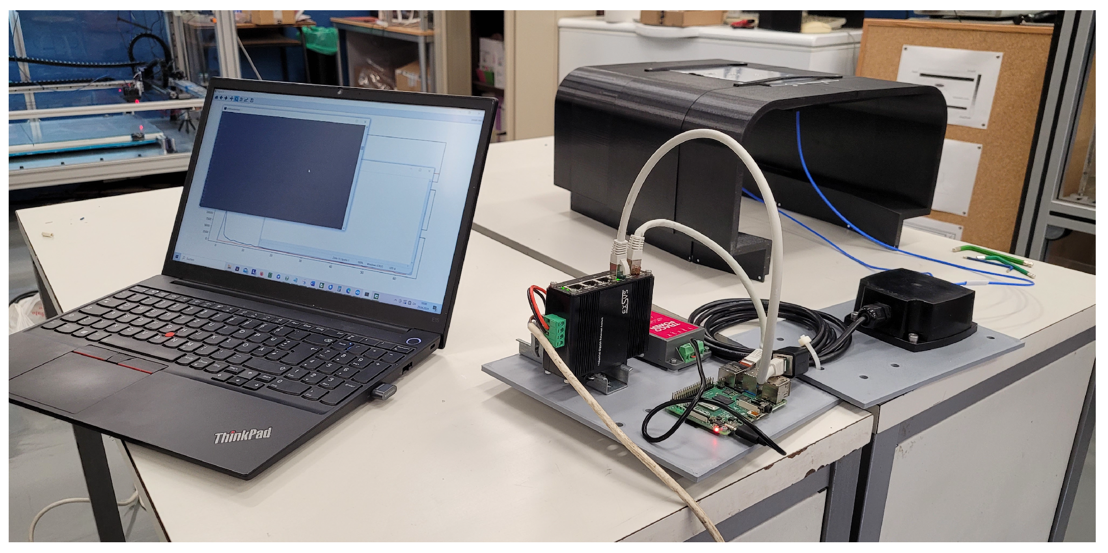
2.3. Data Acquisition and Analysis
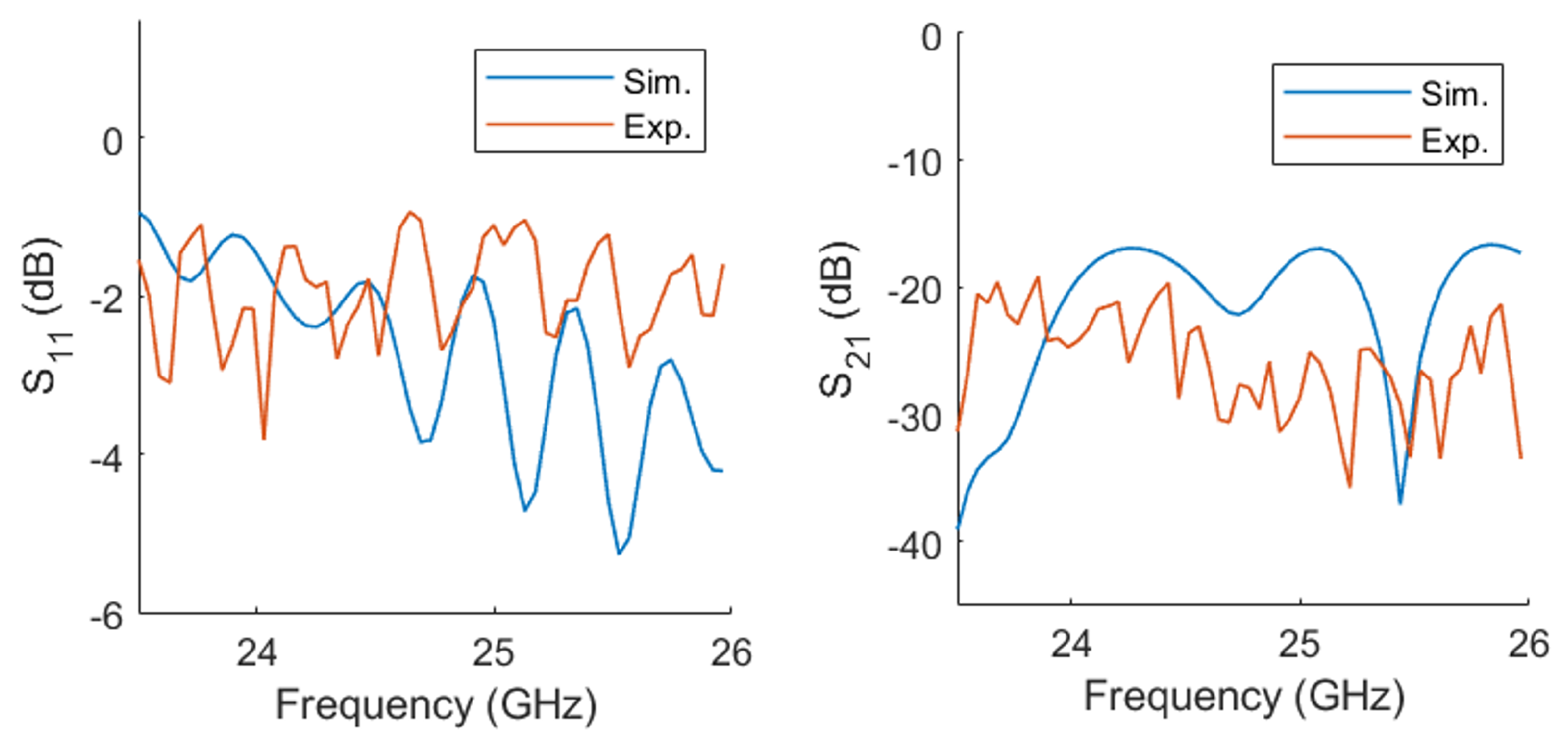
The sensor setup for this experiment consists of an sR1030 radar from IMST GmbH (Kamp-Lintfort, Germany) for radar sensing and a Raspberry Pi for data acquisition, data validation, pre-processing, data storage, and wireless data transfer to a laptop. Despite not being a fully fledged VNA, the radar could provide the same insights, and its smaller size is also better suited for in-flight testing. The radar system was operated via Power-over-Ethernet using a corresponding switch. Since the Raspberry Pi needs 5 V while the PoE-switch needs at least 24 V, a DC-to-DC converter was used to power both parts from the same 24 V source.
A schematic of the setup is shown in Figure 5. The sR1030 radar system sends out its frequency ramps into the waveguide from 23.5 GHz to 26 GHz with its maximum bandwidth of 2.5 GHz. The setup, which was mounted on the UAV, can be seen in Figure 6. This waveguide is fully integrated into the housing of the drone as shown in Figure 7. For the experiments, the sensor setup was mounted inside the LIBIS UAV from the Polytechnic University of Madrid. For safety reasons, the drone was tied to a laboratory table so that it could hover slightly above the table. Photos of the final setup, including the drone prototype, can be seen in Figure 8.
The waveguide has screws that can be removed from the top, creating holes through which EW can leak into the surrounding area. This leads to a change in the detected waves at the end of the waveguide. During the measurements, the seven screws are always removed in exactly the same order. Due to the high sensitivity, even partial rotations of the screws already result in signal changes, hence influencing the damage indicator. In each measurement, screws can only be removed one after another, and the trend of the damage indicators can be analyzed.
The time domain data recorded by the radar are sent to the Raspberry Pi using a TCP connection, where the signals are first checked for completeness. If a measured frequency ramp is incomplete, it is discarded and another one is requested from the radar. One measurement consists of 100 ramps. Once these have been recorded, they can be accessed through a Wi-Fi connection from the Raspberry Pi. Further evaluation takes place on a laptop. For the analysis and calculation of damage indicators, the ramps of a measurement are averaged and Fourier-transformed. The averaged ramps in the frequency domain s can be used to calculate the damage indicator (DI) as the RMS relative to a baseline signal b:
D I = i = 0 N ( s i b i ) 2 .
In this equation, N denotes the number of samples. A higher damage indicator here means greater damage.

3. Results

First, a series of measurements were carried out with the drone switched off. These measurements serve as a basis for comparison. If the same trend is visible in a similar form later in flight, then the influence of motor vibrations and other external influences during flight is negligible. The result can be seen in Figure 9. Each removed screw results in a significant increase in the damage indicator.
For simulating flight conditions, the drone hovered above the table in the laboratory. As it was fixed to the table for safety reasons, the flight control system could not change the position of the drone as desired in order to remain balanced. This repeatedly led to heavy touchdowns and impacts on the table, causing the drone to shake. These impacts are comparable to the effect of outdoor turbulences, but many times stronger. It can be assumed that no similarly strong effects are to be expected during a real flight.
Figure 10 shows the raw signals in the time domain together with the signals resulting from the FFT in the frequency domain. The 100 ramps of a measurement were averaged. Semi-transparent areas show the minimum and maximum variances of the ramps from their mean value. It should be noted that the variances are very small even in flight. The setup is very precise and has high repeatability despite external influences. Only at low frequencies in the frequency domain is a larger variance visible, which is why the low frequencies are ignored by a range gating when calculating the DI.
Figure 11 shows the DI during hovering with the same clear trend as when the drone was on the ground. For a systematic evaluation, each condition was repeated three times. In the figure, the baseline state has only two bars, because one measurement serves as a reference for all other measurements and is therefore zero. The drone was temporarily on ground between the measurements. The three DI values for each condition differ only minimally from each other and agree sufficiently well. Only the last measurement in condition Dam. 5 showed an outlier. After carrying out the three measurements of Dam. 5, one battery of the drone had to be recharged. After that, an additional measurement was taken to ensure continuity. The DI of this fourth measurement is slightly higher than the DIs of the first three measurements. Apparently, the DIs are sensitive to the available power of the motors. However, reloading does not mask the effect of the next damage step. In a real-world application, changes in engine power during flight would have to be taken into account. The same is probably true for all dynamic changes during flight. The extent to which these factors influence the DI in a significant way still needs to be researched.
Both the results on the ground and in hovering flight also show the influence of the size of the removed screws. The size of the screws starts with a diameter of 2 mm and increases with Dam. 2 to 4 mm, with Dam. 4 to 6 mm, and with Dam. 5 to 8 mm. The steps from Dam. 4 to Dam. 5 and Dam. 5 to Dam. 6 are visible in the measurements on the ground in Figure 9. In the measurements during hovering flight, the step from Dam. 3 to Dam. 4 can also be seen in Figure 11.

4. Conclusions

It was demonstrated in this work that guided electromagnetic waves in K-band are a promising tool for reliable damage detection in airspace structures under real-world conditions. It was shown through an experimental campaign that damage in the order of only 2 mm can be identified during controlled flight operation in the laboratory with severe disturbances, showing robustness against operative flight conditions. Although a simplified device under test was studied here, i.e., an aluminum plate containing holes, the approach can easily be applied to more complex aerospace components.
Future research can use flexible dielectric substrates that conform to the irregular shape of the shell, e.g., via flexible dielectric sheets [25]. It is expected that temperature variations will also influence the detectability of damage, because the sensor extends and shrinks. Temperature influence studies under controlled laboratory conditions have been planned to quantify such effects; see related studies in the context of ultrasonic SHM systems [26]. Suitable compensation strategies in post-processing must be developed. Another aspect is related to the performance assessment of the SHM system, e.g., in terms of probability of detection (POD). In this context, the authors have already proposed some preliminary developments that might by transferred and extended in the context of guided electromagnetic waves [27].

Author Contributions

Conceptualization, M.M., J.S., D.d.R.V., M.R., S.B. and J.M.; methodology, M.M., J.S., C.G., M.R., S.B., V.M., J.M. and V.K.; software, M.M., J.S. and S.B.; validation, M.M., J.S. and S.B.; formal analysis, M.M., J.S., S.B. and V.M.; investigation, M.M., J.S., D.d.R.V., M.R., S.B. and J.M.; resources, C.G., D.d.R.V. and J.M.; data curation, M.M., J.S. and S.B.; writing—original draft preparation, M.M., J.S., D.d.R.V., M.R., V.M. and J.M.; writing—review and editing, M.M., J.S., M.R., V.M. and J.M.; visualization, J.S., D.d.R.V. and M.R.; supervision, D.d.R.V., J.M. and V.K.; project administration, D.d.R.V., J.M. and V.K.; funding acquisition, D.d.R.V. and J.M. All authors have read and agreed to the published version of the manuscript.

Funding

This research was funded by the Federal Ministry for Economic Affairs and Energy, grant number 20Q1911C.

Institutional Review Board Statement

Not applicable.

Informed Consent Statement

Not applicable.

Data Availability Statement

The raw data supporting the conclusions of this article will be made available by the authors on request.

Conflicts of Interest

Author Carsten Günner was employed by the company IMST GmbH. The remaining authors declare that the research was conducted in the absence of any commercial or financial relationships that could be construed as a potential conflict of interest.

Abbreviations

The following abbreviations are used in this manuscript:
DUTDevice under test;
EWElectromagnetic wave;
SHMStructural health monitoring;
UAVUnmanned aerial vehicle.

References

  1. Rao, M.E.; Simon, J.; Moll, J.; Schütz, M.F. Real-time onboard propeller fault diagnosis of autonomous delivery drones through vibration analysis. Struct. Health Monit. 2025, 14759217251327224. [Google Scholar] [CrossRef]
  2. Ghazali, M.H.M.; Rahiman, W. Vibration-Based Fault Detection in Drone Using Artificial Intelligence. IEEE Sens. J. 2022, 22, 8439–8448. [Google Scholar] [CrossRef]
  3. Liu, W.; Chen, Z.; Zheng, M. An Audio-Based Fault Diagnosis Method for Quadrotors Using Convolutional Neural Network and Transfer Learning. In Proceedings of the 2020 American Control Conference (ACC), Denver, CO, USA, 1–3 July 2020; pp. 1367–1372. [Google Scholar] [CrossRef]
  4. Soria Gomez, M.; Koschlik, A.K.; Arts, E.; Raddatz, F. Non-destructive evaluation of the condition of a UAV’s propellers by means of acoustics. In Proceedings of the NDE 4.0, Predictive Maintenance, and Communication and Energy Systems in a Globally Networked World, Long Beach, CA, USA, 6 March–11 April 2022; Meyendorf, N.G., Niezrecki, C., Farhangdoust, S., Eds.; SPIE: Bellingham, WA, USA, 2022; p. 19. [Google Scholar] [CrossRef]
  5. Kharkovsky, S.; Zoughi, R. Microwave and millimeter wave nondestructive testing and evaluation - Overview and recent advances. IEEE Instrum. Meas. Mag. 2007, 10, 26–38. [Google Scholar] [CrossRef]
  6. Moll, J. Guided electromagnetic waves for damage detection and localization in metallic plates: Numerical and experimental results. Int. J. Microw. Wirel. Technol. 2020, 12, 455–460. [Google Scholar] [CrossRef]
  7. Memmolo, V.; Moll, J.; Moix Bonet, M.; Schmidt, D.; Krozer, V. Ultra-wideband microwave leakage monitoring for stringer debonding detection in carbon composite fuselage structures. NDT E Int. 2024, 142, 103006. [Google Scholar] [CrossRef]
  8. Liu, L.; Ju, Y. A high-efficiency nondestructive method for remote detection and quantitative evaluation of pipe wall thinning using microwaves. NDT E Int. 2011, 44, 106–110. [Google Scholar] [CrossRef]
  9. Sasaki, K.; Katagiri, T.; Yusa, N.; Hashizume, H. Demonstration of the Applicability of Nondestructive Microwave Testing to the Long-Range Inspection of Inner-Surface Cracks in Tubes. Mater. Trans. 2017, 58, 692–696. [Google Scholar] [CrossRef]
  10. Chen, G.; Katagiri, T.; Song, H.; Yusa, N.; Hashizume, H. Detection of cracks with arbitrary orientations in a metal pipe using linearly-polarized circular TE11 mode microwaves. NDT E Int. 2019, 107, 102125. [Google Scholar] [CrossRef]
  11. Abbasi, K.; Ito, S.; Hashizume, H. Microwave Detection of Longitudinal Crack and Identification of Its Location in Straight Pipe. J. Power Energy Syst. 2008, 2, 538–544. [Google Scholar] [CrossRef]
  12. Chen, G.; Katagiri, T.; Yusa, N.; Hashizume, H. In-pipe crack detection for multiple diameters using TE11 mode microwaves. Int. J. Appl. Electromagn. Mech. 2020, 64, 39–46. [Google Scholar] [CrossRef]
  13. Sasaki, K.; Katagiri, T.; Yusa, N.; Hashizume, H. Experimental verification of long-range microwave pipe inspection using straight pipes with lengths of 19–26.5 m. NDT E Int. 2018, 96, 47–57. [Google Scholar] [CrossRef]
  14. Chen, G.; Katagiri, T.; Yusa, N.; Hashizume, H. Design of a dual-port, side-incident microwave probe for detection of in-pipe damage. Meas. Sci. Technol. 2020, 31, 125001. [Google Scholar] [CrossRef]
  15. Chen, G. Investigation of the effect of a bend on pipe inspection using microwave NDT. NDT E Int. 2020, 110, 102208. [Google Scholar] [CrossRef]
  16. Katagiri, T.; Chen, G.; Yusa, N.; Hashizume, H. Demonstration of detection of the multiple pipe wall thinning defects using microwaves. Measurement 2021, 175, 109074. [Google Scholar] [CrossRef]
  17. Chen, G.; Guo, Y.; Katagiri, T.; Song, H.; Tomizawa, T.; Yusa, N.; Hashizume, H. Multivariate probability of detection (POD) analysis considering the defect location for long-range, non-destructive pipe inspection using electromagnetic guided wave testing. NDT E Int. 2021, 124, 102539. [Google Scholar] [CrossRef]
  18. Rao, M.E.; Memmolo, V.; Moll, J.; Krozer, V. Structural Health Monitoring of Aerospace Structures using Guided Electromagnetic Waves in a Dielectric Waveguide at Ka-Band. E-J. Nondestruct. Test. 2024, 29. [Google Scholar] [CrossRef]
  19. Pozar, D.M. Microwave Engineering, 4th ed.; Wiley: Hoboken, NJ, USA, 2012. [Google Scholar]
  20. Jie, H.; Zhao, Z.; Li, H.; Gan, T.H.; See, K.Y. A Systematic Three-Stage Safety Enhancement Approach for Motor Drive and Gimbal Systems in Unmanned Aerial Vehicles. IEEE Trans. Power Electron. 2025, 40, 9329–9342. [Google Scholar] [CrossRef]
  21. Jie, H.; Zhao, Z.; Zeng, Y.; Chang, Y.; Fan, F.; Wang, C.; See, K.Y. A review of intentional electromagnetic interference in power electronics: Conducted and radiated susceptibility. IET Power Electron. 2024, 17, 1487–1506. [Google Scholar] [CrossRef]
  22. Blond, K.; O’Brien, T.; Thompson, N.; Piotrowski, D.; Clark, A. Comparative Vacuum Monitoring Solutions to Advance U.S. Air Force KC-46A Condition-Based Maintenance Plus. Aerospace 2023, 10, 587. [Google Scholar] [CrossRef]
  23. Simoncelli, M.; Zucca, M.; Ghilardi, M. Structural health monitoring of an onshore steel wind turbine. J. Civ. Struct. Health Monit. 2024, 14, 1423–1437. [Google Scholar] [CrossRef]
  24. Chang, S.; Deng, Y.; Zhang, Y.; Zhao, Q.; Wang, R.; Zhang, K. An Advanced Scheme for Range Ambiguity Suppression of Spaceborne SAR Based on Blind Source Separation. IEEE Trans. Geosci. Remote Sens. 2022, 60, 5230112. [Google Scholar] [CrossRef]
  25. Hussain, M.; Zahra, H.; Abbas, S.M.; Zhu, Y. Flexible Dielectric Materials: Potential and Applications in Antennas and RF Sensors. Adv. Electron. Mater. 2024, 10, 2400240. [Google Scholar] [CrossRef]
  26. Gorgin, R.; Luo, Y.; Wu, Z. Environmental and operational conditions effects on Lamb wave based structural health monitoring systems: A review. Ultrasonics 2020, 106114. [Google Scholar] [CrossRef]
  27. Mueller, I.; Memmolo, V.; Tschöke, K.; Moix-Bonet, M.; Möllenhoff, K.; Golub, M.; Venkat, R.S.; Lugovtsova, Y.; Eremin, A.; Moll, J. Performance Assessment for a Guided Wave-Based SHM System Applied to a Stiffened Composite Structure. Sensors 2022, 22, 7529. [Google Scholar] [CrossRef]
Figure 1. LIBIS—electrically powered UAV designed for versatile aerial operations with a maximum takeoff weight of 25 kg and a wingspan of 2 m.
Applsci 15 06478 g001
Figure 2. Schematic representation of the waveguide with a propylene matrix in two spatial dimensions. The waveguide covers 200 mm of the DUT for determining its structural health. The direction of EM wave propagation is denoted as z.
Applsci 15 06478 g002
Figure 3. (a) Complete rectangular waveguide design containing two K-connectors, a polypropylene substrate, metallic housing, and an aluminum test plate as the DUT. (b) The bolts (numbered) of the test plate are removed one by one to reduce electromagnetic energy inside the waveguide.
Applsci 15 06478 g003
Figure 4. Comparison of numerical and experimental signals in frequency domain from 23.5 GHz to 26 GHz for the case of reflection ( S 11 ) and transmission ( S 21 ).
Applsci 15 06478 g004
Figure 5. Data processing pipeline.
Applsci 15 06478 g005
Figure 6. The setup of the experiment before it is mounted on the UAV.
Applsci 15 06478 g006
Figure 7. Photo of the top of the waveguide with seven screws that can be removed.
Applsci 15 06478 g007
Figure 8. (left) Photo showing the radar, Raspberry Pi, and waveguide; (right) photo of the complete drone prototype.
Applsci 15 06478 g008
Figure 9. Development of the DI for the drone on the ground. A clear trend can be observed as the number of removed screws increases.
Applsci 15 06478 g009
Figure 10. (top) Time domain data of the first two reference measurements and the first measurement of every waveguide leak state. (bottom) Frequency domain data for every measurement shown above.
Applsci 15 06478 g010
Figure 11. RMS-based damage indicators of the reference and the seven damaged states given by removed screws for the hovering drone.
Applsci 15 06478 g011
Disclaimer/Publisher’s Note: The statements, opinions and data contained in all publications are solely those of the individual author(s) and contributor(s) and not of MDPI and/or the editor(s). MDPI and/or the editor(s) disclaim responsibility for any injury to people or property resulting from any ideas, methods, instructions or products referred to in the content.

