1. Introduction
With the continuous emergence of high-rise buildings worldwide, the demand for structural components with excellent mechanical performance has been growing. Currently, reinforced concrete (RC) columns are widely adopted as the primary load-bearing elements in construction. However, RC columns involve complex construction processes and fail to fully utilize the superior mechanical properties of steel. Consequently, concrete-filled steel tube (CFST) components have emerged as an effective alternative.
Concrete-filled steel tube means to pour concrete into steel pipe, which makes steel pipe and core concrete work together to endure exterior loads. The external steel tube of such components not only bears compressive loads but also confines the internal concrete, thereby further enhancing the compressive capacity. At present, concrete-filled circular steel tubes are mostly used in workshops, bearing columns, and arch ribs of bridges. For instance, the Yajisha bridge in Guangzhou is a half-through concrete-filled steel tube arch bridge, which is composed of six concrete-filled circular steel tubes forming a lattice arch rib. Similarly, the main tower of the Houhu stayed-cable bridge in Wuhan incorporates concrete-filled circular steel tubes. Carbon-fiber-reinforced polymer (CFRP) is a lightweight material with exceptional tensile strength [
1,
2,
3]. It exhibits advantages such as corrosion resistance, fatigue resistance, and minimal creep. Applying CFRP to enhance the ultimate bearing capacity of CFST structures has become an inevitable trend. In this paper, the concrete-filled circular CFRP–steel middle long columns are made of circular steel middle long columns, which are poured with concrete inside and wrapped with CFRP on the outer surface of the steel tube in a circular direction. The axial compressive capacity of concrete-filled steel tubes is enhanced by the high strength tensile property of CFRP so as to strengthen the ultimate bearing capacity of concrete-filled steel tubes [
4,
5]. Moreover, the bending stiffness and ductility of the CFST are improved, and the local buckling is prevented in the case of large lateral deflection.
In the past two decades, many researchers have raised a variety of discussions in this field. For example, Al-Mekhlafi et al. [
6] investigated the behavior of cold-formed thin-walled circular stainless steel tube stub columns fully wrapped with CFRP through axial compression tests and ABAQUS finite element analysis. Experimental and numerical results demonstrated that this strengthening method effectively enhances the ultimate compressive strength of columns. Mahdi et al. [
7] experimentally investigated the eccentric compression performance of RC columns strengthened with CFRP and steel fibers. Results demonstrated CFRP effectively enhanced both load-bearing capacity and ductility, while steel fibers mainly improved ductility. Karimian et al. [
8] examined CFRP-strengthened circular CFT stub columns with initial imperfections. Using experimental tests and ABAQUS simulations with Riks nonlinear analysis, they found that horizontal imperfections more significantly reduce load-bearing capacity than vertical ones, while CFRP strengthening effectively improves capacity, alleviates stress concentration, and inhibits local buckling. Choi [
9,
10] conducted sequential studies on the axial compression performance of circular CFT stub columns, first analyzing their fundamental mechanical behavior and then developing a theoretical model to predict the axial yield capacity of CFRP-confined specimens.
L. Liu [
11] used ANSYS to simulate the axial compression test of concrete-filled FRP-steel stub columns and obtained the ultimate bearing capacity, which is in line with the test results. By using the ABAQUS, the load–strain curve and stress figures of concrete-filled CFRP–steel stub columns under axial load are simulated, which are consistent with the test results of Z.-X. Jiang [
12]. Y. Che [
13] carried out experimental research and finite element analysis on concrete-filled CFRP–steel stub columns under axial compression. Y. Xiao [
14] defined a “confined concrete-filled steel tube” by the CFRP hoop coefficient, carried out experimental research, and established a theoretical analysis model. However, most of the above studies aimed at research on concrete-filled CFRP–steel stub columns and long columns. The study of concrete-filled CFRP–steel middle long columns is relatively limited. Especially the comprehensive research on the numerical simulation analysis of concrete-filled circular CFRP–steel middle long columns.
In this paper, the axial compression test of ten different concrete-filled circular CFRP–steel middle long columns was carried out. Combined with theoretical analysis, the calculation method of bearing capacity of it was found. The influence of different concrete strength grades, layers of CFRP, and wall thicknesses of steel tubes on the ultimate bearing capacity of samples is discussed. Then, the load midspan deflection curves and ultimate bearing capacity were obtained by finite element analysis software ANSYS2021R1. Compared with the test results, the correctness and practicability of the simulation analysis of concrete-filled circular CFRP–steel middle long columns are further verified, which are of great significance for analyzing the ultimate bearing capacity and theoretical derivation of it.
2. Axial Compression Test
2.1. The Test Sample
The steel tubes used in the samples are Q235 circular cross-section steel tubes with an inner diameter of 160 mm and outer diameters of 165 mm, 167 mm, and 168.5 mm. The cast-in-place concrete column is a cylinder with a diameter of 160 mm. The lengths of the columns are 500 mm, 1000 mm, and 1333 mm. A cover plate is added at the upper and lower ends, with a square cross-section of side length 385 mm and thickness 10 mm. The plate is also made of Q235 steel [
15]. Strength grades of concrete: C40, C50, and C60 [
16]. Number of CFRP layers: 0, 1, 2, and 3. The specific parameters of the samples are shown in
Table 1. The experimental program included 10 groups of column specimens with different configurations, with each group comprising 3 identical specimens for parallel testing to minimize experimental errors.
2.2. Material Performance
2.2.1. Concrete Constituent Materials
The cement used was P.O 42.5 grade ordinary Portland cement. The coarse aggregate was crushed limestone with a particle size range of 5–20 mm and continuous gradation. Natural river sand with a fineness modulus of 2.87 was selected as the fine aggregate. To improve workability, a polycarboxylate-based high-performance water reducer (transparent light-yellow in appearance) with a water reduction rate of 25% was employed.
2.2.2. Concrete Mix Proportion
The mix proportions were designed in accordance with JGJ55-2011 “Specification for Mix Proportion Design of Ordinary Concrete” [
16]. The designed concrete strength grades were C40, C50, and C60, with the corresponding mix proportions shown in
Table 2.
2.2.3. Mechanical Properties of Materials
The parameters of the concrete, steel pipe, and CFRP used in the experiment are shown in
Table 3,
Table 4 and
Table 5.
2.3. Experimental Process
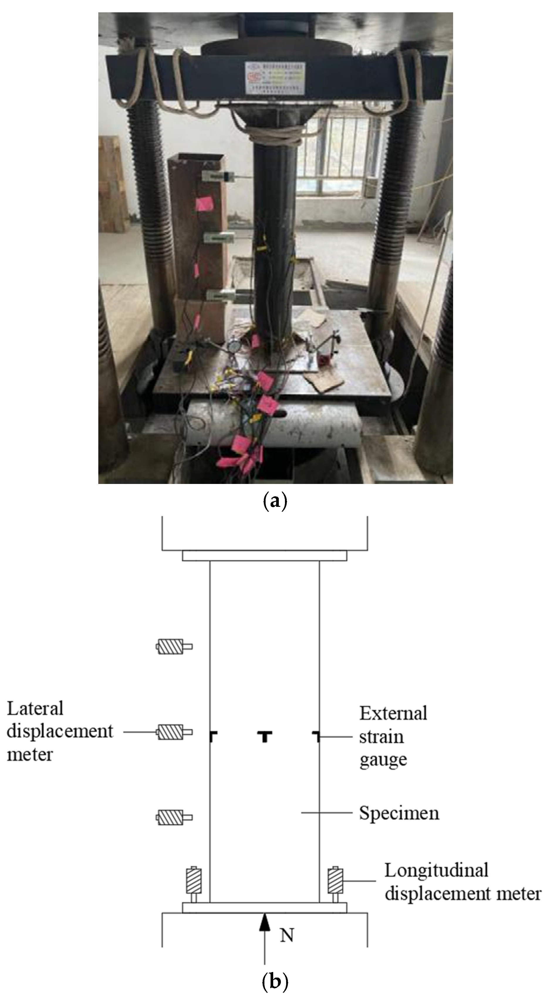
A 500 t microcomputer-controlled electro-hydraulic servo pressure testing machine was used for the axial compression experiment. As shown in
Figure 1, five displacement gauges were, respectively, set at the 1/4 equidistant point of the component and the bottom plate and were used to measure lateral displacement and longitudinal displacement. Four pairs of longitudinal and circumferential resistance strain gauges were set at the middle section of the outer wall of the steel pipe along the circumference and were used to measure the strain at the middle section of the outer wall of the steel pipe [
17,
18,
19]. After pasting CFRP, another four strain gauges were set at the middle section of the column in the horizontal direction. The layout of the strain gauges is based on the relevant provisions of the national standards “Metallic Materials—Tensile Testing at Ambient Temperature” (GB/T 228-2002) [
20] and “Test Method for Tensile Properties of Oriented Fiber Reinforced Plastics” (GB/T 3354) [
21]. Dynamic and static strain collector DF3817F was used for data acquisition. The data collection was carried out from the beginning of loading the samples. At this time, the pressure gauge pointer of the testing machine started to rotate, and the data collection was uninterrupted during the test until the samples were damaged. Compared with the static strain collector, the dynamic and static collector has obvious advantages, which can be real-time online monitoring, alarming, and printing. It can draw graphics in the software, saving labor costs and reducing errors caused by manual recording so as to improve the overall work efficiency in the test process.
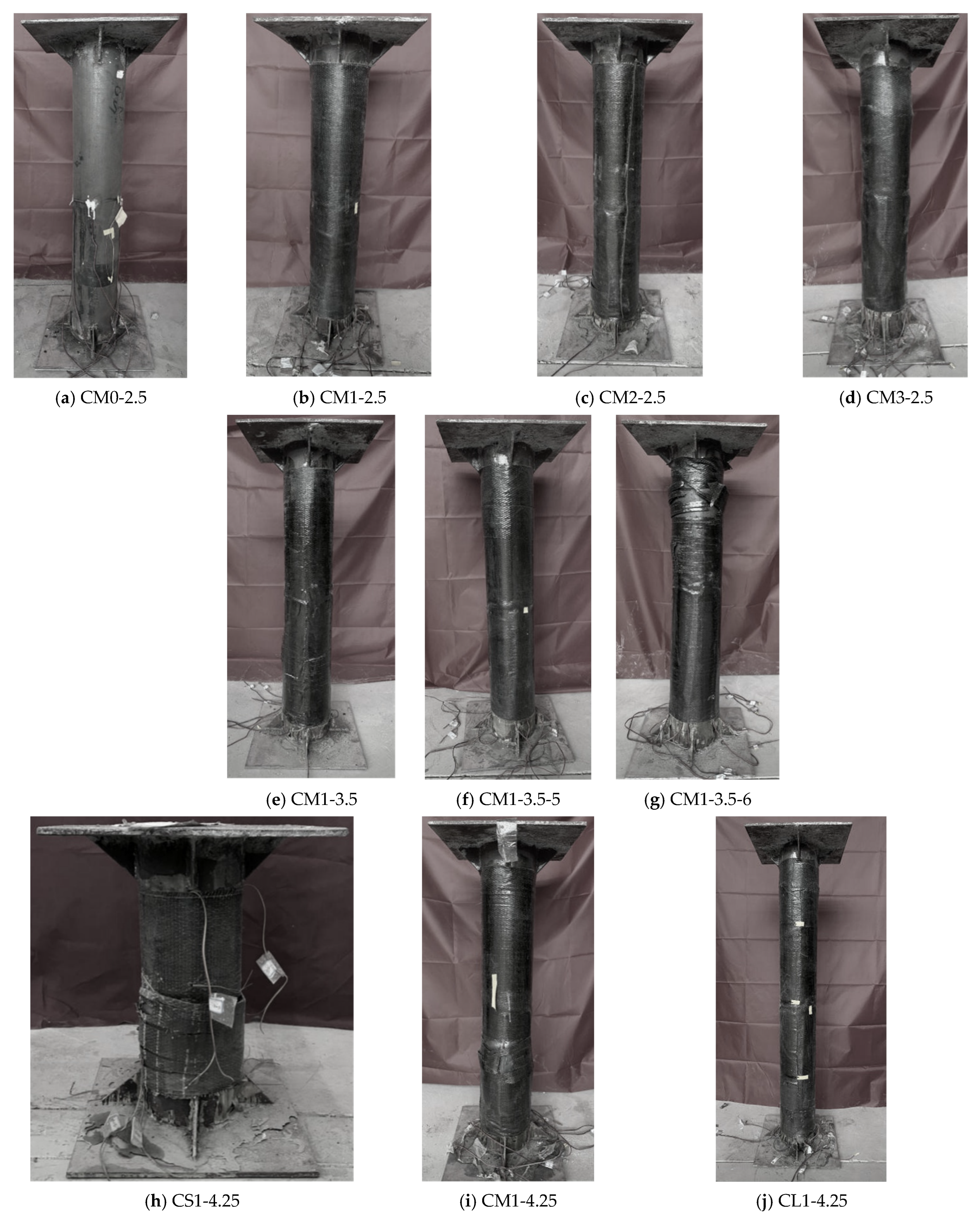
Before the test begins, the upper and lower surfaces of samples should be calibrated and leveled to prevent eccentric compression. When the surface is paved with fine sand, it is leveled horizontally. In order to avoid uneven edges, steel sheets were inserted into the four corners to realize the basic leveling of the surface. In the elastic range, the load of each stage was about 1/10 of the estimated ultimate load. When the steel pipe yielded, the load of each stage was about 1/15 of the estimated ultimate load. When the sample was close to failure, the load of each stage was about 1/20 of the estimated ultimate load, and the load reached a maximum when the pressure gauge pointer of the testing machine began to return to zero. In this paper, the ultimate bearing capacity is defined as the maximum load that the specimen can bear. At this time, the brittle failure of CFRP will occur, and a large cracking sound can be heard. If the loading continues, the elastoplastic bending instability of the sample will occur. In order to ensure the safety of the test, the test is terminated [
22,
23,
24]. The failure mode of all specimens is shown in
Figure 2.
2.4. Experimental Results
Based on the aforementioned testing methodology, the experimental data are presented in
Table 6.
2.5. Analysis of Results
The experimental observations revealed that all specimens exhibited three distinct behavioral phases: elastic, elastoplastic, and failure stages. During the elastic stage, minimal deformation occurred with the load primarily carried by the concrete core and steel tube. The elastoplastic stage featured progressive concrete cracking and increased lateral deformation, where the steel tube simultaneously resisted axial compression while collaborating with CFRP to restrain transverse expansion. Ultimate failure manifested through concrete crushing, severe steel tube buckling, and CFRP rupture.
Experimental results demonstrate that the ultimate bearing capacity of circular steel tube–CFRP confined concrete intermediate columns is synergistically influenced by concrete strength, steel tube thickness, CFRP layers, and slenderness ratio. While increased concrete strength (up to 20%) and thicker steel tubes (≤20% improvement) provide modest enhancements, CFRP reinforcement shows remarkable effectiveness—specimens with 1, 2, and 3 CFRP layers exhibit 42.5%, 69.4%, and 88.4% capacity increases, respectively, albeit with diminishing returns beyond optimal layer counts. Conversely, capacity reduction correlates strongly with higher slenderness ratios, completing this comprehensive performance characterization for composite column design.
3. Theoretical Calculation of Ultimate Bearing Capacity
3.1. The Selection of Circumferential Tensile Stress in CFRP
According to the analysis of the test results, when the concrete strength grades are C40, C50, and C60, the circumferential tensile strains of CFRP failure are only 68%, 59%, and 50% of the ultimate tensile strain in the tensile test. It can be seen that the actual tensile strength is 68%, 59%, and 50% of the ultimate tensile strength. Then, the actual circumferential tensile strength of CFRP is taken as follows:
is the effective restraint coefficient of CFRP. When the concrete strength grades are C40, C50, and C60, the values of are 0.68, 0.59, and 0.5.
3.2. Confinement Effect Coefficient
In order to analyze the influence of the circular steel tube and CFRP, the confinement effect coefficient of the circular steel tube
, the confinement effect coefficient of CFRP
, and the synthetical confinement effect coefficient
are adopted as follows:
where
,
, and
are the cross-sectional areas of the circular steel tube, concrete, and CFRP, respectively.
,
, and
are the yield strength of the circular steel tube, the concrete compression strength, and the ultimate tensile strength of CFRP, respectively.
It can be seen from the formula that the influencing factors of the restraint effect coefficient of concrete-filled circular CFRP–steel middle long columns are the type of steel, the wall thickness of the steel tube, the number of layers of CFRP, the tensile strength of CFRP, and the strength grades of concrete.
3.3. Restraint Tightening-Ring Force of Concrete
In order to analyze the binding effect of the circular steel tube on concrete, the circular steel tube working coefficient
and the ratio of principal stress to uniaxial compressive strength under ultimate state of concrete
are adopted as follows:
As for concrete-filled circular steel tubular middle long columns, there are many factors affecting the working coefficient of the circular steel tube participating in concrete confinement. So, is a constant value. In order to facilitate the calculation, this paper revises it according to the test results. For the concrete-filled circular CFRP–steel middle long columns, the value of is taken as 0.3, which is in good agreement with the test results.
3.4. The Formula of Ultimate Bearing Capacity
The calculation formula of the ultimate bearing capacity of concrete-filled circular CFRP–steel middle long columns
is as follows, where
is the ultimate bearing capacity formula of concrete-filled circular CFRP–steel stub columns.
is a parameter of concrete materials. is obtained by the statistics and regression of the experimental data, which can be used only in the case of .
3.5. Comparison of Ultimate Bearing Capacity
The theoretical calculation of the ultimate bearing capacity is compared with the test results, as shown in
Table 7. The results show that the minimum value of
is 0.97, the maximum value is 1.05, and the average value is 1.002. So, the maximum error is 5%, the minimum error is 1%, and the average error is only 1.8%. It indicates that the theoretical formula has little error with the test results, which can better measure the ultimate bearing capacity of concrete-filled circular CFRP–steel middle long columns and provide theoretical support for engineering practice.
4. Finite Element Calculation
With the rapid development of science and technology, the use of ANSYS finite element software for experimental simulation has become more and more common [
25,
26,
27,
28]. In order to make the finite element analysis results reliable, this paper tries to set the model according to the actual size of the specimen. Meanwhile, in order to reduce the complexity of post-processing calculation, the accuracy of steel tube and concrete mesh generation is simplified to avoid the calculation complexity due to high accuracy, which will lead to the non-convergence of calculation results [
29,
30].
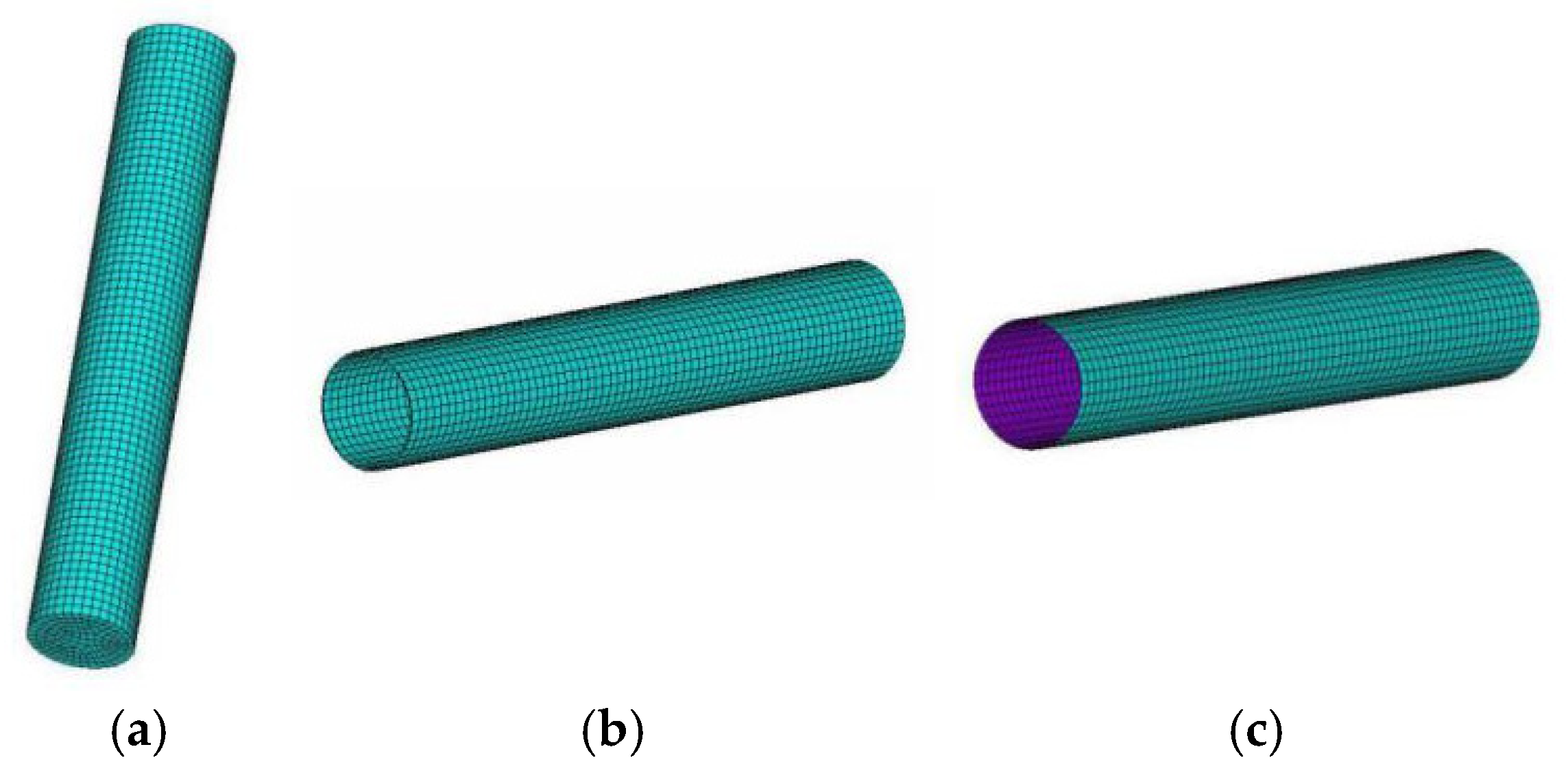
4.1. The Selection of Unit Type
In ANSYS finite element analysis, the selection of element types is based on material characteristics and structural configurations. The SOLID65 element is widely adopted for nonlinear simulation of concrete materials due to its unique constitutive model incorporating tensile cracking and compressive crushing capabilities. The SOLID45 element, as a three-dimensional solid element, is suitable for simulating the mechanical behavior of steel tubes. Considering the thin-walled characteristics of CFRP materials (with thickness dimension significantly smaller than in-plane dimensions), shell elements are more appropriate for modeling. This element selection scheme accurately represents the mechanical properties of each constituent material, ensuring the reliability of numerical simulations.
SOLID65 was used for the concrete units, and MISO was adopted as a reinforcement criterion. The stress was set to not release after concrete cracking. SOLID 45 was used for the steel pipe unit. SHELL181 was used for the CFRP unit, and the BKIN was adopted for CFRP. This element can not only simulate the lateral bending deformation of concrete-filled circular CFRP columns but also establish different sections for delamination so as to simulate different layers of CFRP [
31].
4.2. Modeling and Meshing
Because the influence of slip is more complex, this paper does not consider slip between the elements. So, the glue command is used to link the model, assuming that it is fully bonded, and then the element attributes are given to each entity. In this paper, the concrete, steel pipe, and CFRP were meshed into different forms. Firstly, according to the types of concrete, steel pipe, and CFRP, their lines were meshed with different precisions. Secondly, the mesh of concrete and steel tube was hexahedron, and the mesh generation method was volume sweeping, while CFRP was mapped face meshing. The meshed model is shown in
Figure 3.
4.3. Applying Loads and Calculation Method
Due to the accuracy of mesh generation, the base plate model was not established in this model. In order to simulate the constraints of the pad model, the joints were coupled at the upper and lower ends of the model. Then, the surface loads were applied to the top of concrete-filled circular CFRP–steel middle long columns. In this paper, the nonlinear static analysis was adopted. According to the convergence rule of force, the acceptance value was 0.05. The calculation stop standard was when the transverse tensile stress of CFRP was greater than the actual tensile strength of its material [
32,
33].
5. Analysis of ANSYS Calculation Results
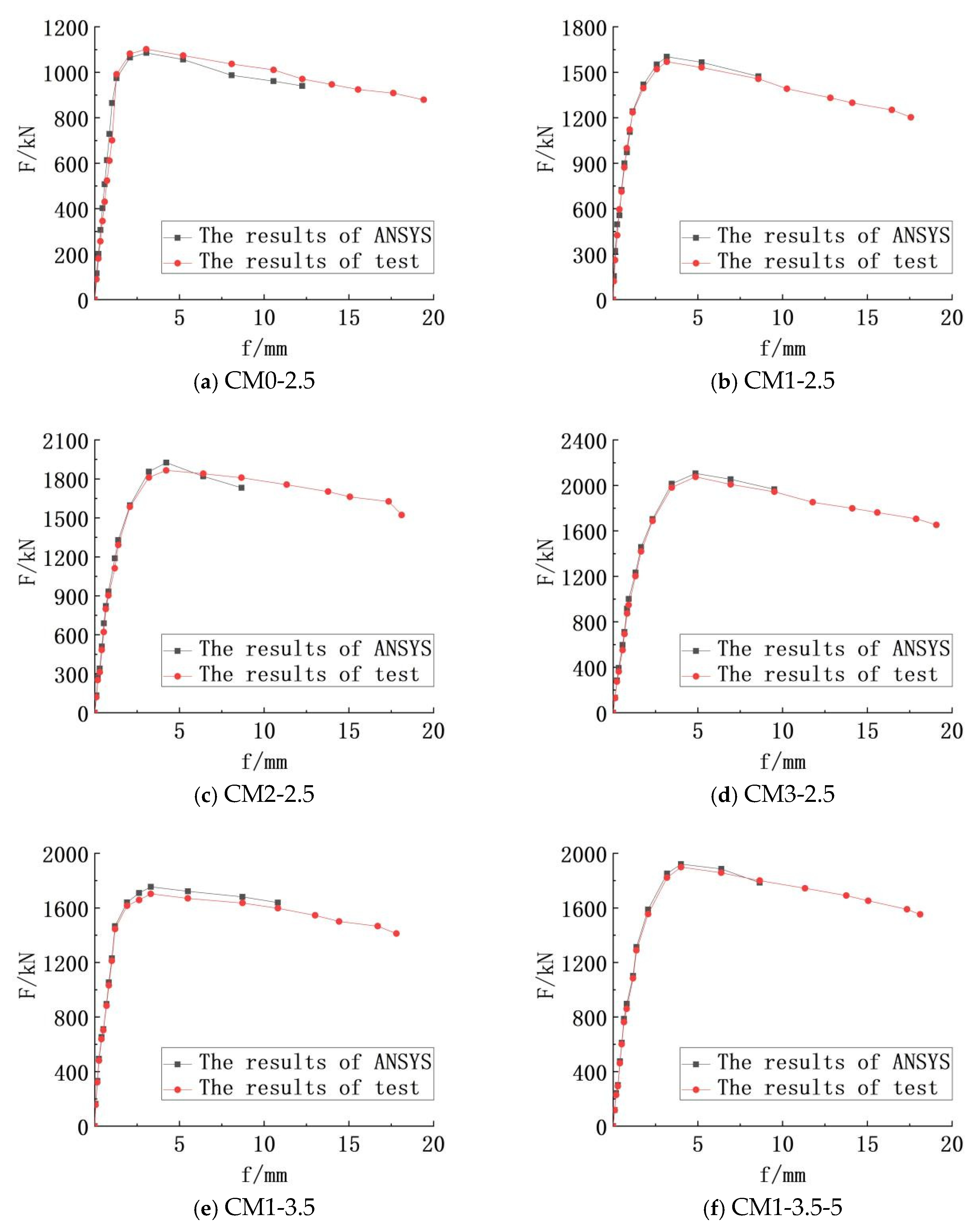
5.1. The Axial Load Versus Displacement of Mid-Span Curves
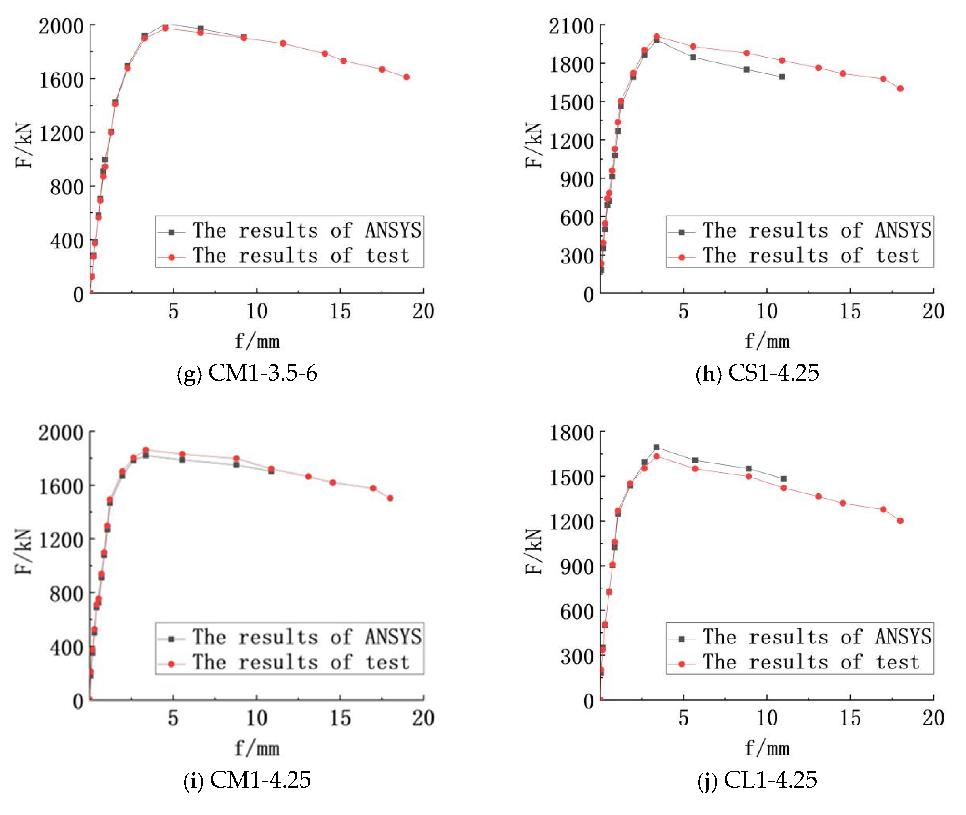
Figure 4 depicts the load versus displacement of mid-span curves, which were drawn after the extraction of ANSYS calculation results. It reflects the failure process of concrete-filled circular CFRP–steel middle long columns. When the bearing capacity is less than 95%, the mid-span deflection increases uniformly and slightly. When the bearing capacity is more than 95%, the mid-span deflection increases significantly. When the ultimate bearing capacity is reached, the outer CFRP will break suddenly after brittle failure, and the deflection begins to increase greatly as the bearing capacity drops rapidly. So, the bearing capacity at the falling point is the ultimate bearing capacity of the member. If the load continues to be applied, obvious bending of the circular steel pipe can be seen. According to the curve, the calculation results of ANSYS are in good agreement with the test results, and the error is small. The simulation error of CM0-2.5, CM3-2.5, CM1-3.5-5, and CS1-4.25 is only 1%. It can be seen that the simulation is accurate and conducive to the analysis of the test.
5.2. The Results of Ultimate Bearing Capacity in ANSYS
According to the results in
Figure 4, the ultimate bearing capacity can be obtained. As shown in
Table 8, the maximum error between the simulation results and the test results is 4%, the minimum error is 1%, and the average error is 2%. It shows that the error of simulation results is small, and it is feasible to use ANSYS to analyze the ultimate bearing capacity.
5.2.1. The Influence of the Number of CFRP Layers
It can be seen from
Table 6 that the ultimate bearing capacity of concrete-filled circular steel middle long columns with one layer of CFRP is increased by 42.5%, that of two layers is increased by 18.9%, and that of three layers is increased by 11.2% compared with that of two layers. This shows that the bearing capacity of the samples can be greatly improved by adding one layer of CFRP, while the increase in bearing capacity decreases sharply when the number of stories reaches two or more layers. This indicates that the single-layer CFRP has an obvious effect on improving the ultimate bearing capacity of concrete-filled circular CFRP–steel middle long columns, while the effect of multi-layer is limited.
5.2.2. The Influence of Concrete Strength Grades
It can be seen from
Table 6 that the ultimate bearing capacity of C50 single-layer CFRP concrete-filled circular steel tubular columns is 11.5% higher than that of C40, that of C60 is 15.9% higher than that of C40, and that of C60 is 3.95% higher than that of C50. The results show that with the increase in concrete strength grades, the ultimate bearing capacity of the samples increases marginally. The improvement range is limited and smaller than that of the number of CFRP layers.
5.2.3. The Influence of Circular Steel Pipe Wall Thickness
It can be seen from
Table 6 that the ultimate bearing capacity of single-layer CFRP concrete-filled circular steel tubular columns with 3.5 mm wall thickness is 8.53% higher than that of 2.5 mm, that of 4.25 mm is 18.6% higher than that of 3.5 mm, and that of 4.25 mm is 9.28% higher than that of 3.5 mm. This indicates that the ultimate bearing capacity of the samples increases as the steel tube wall thickness increases. The influence of the wall thickness is greater than that of concrete strength grades but less than that of the number of CFRP layers.
5.2.4. The Influence of Slenderness Ratio
It can be seen from
Table 6 that the ultimate bearing capacity of single-layer CFRP concrete-filled circular steel tubular columns with 24 slenderness ratios is 7.84% lower than that of 12, that of 32 is 14% lower than that of 24, and that of 32 is 22.97% than that of 12. This indicates that the influence of the slenderness ratio on the ultimate bearing capacity of the samples is only less than that of the number of CFRP layers.
6. Conclusions
This study investigates circular CFRP–steel tube confined concrete intermediate columns, elucidating their working mechanisms and identifying key factors influencing axial compressive performance, thereby filling a critical research gap in this field. Combined with theoretical analysis, the calculation method of its bearing capacity is found, which can provide a reference for design and construction. Furthermore, by numerical simulation of ANSYS, the error of theoretical calculation will be reduced. The following conclusions can be obtained:
(1) It can be seen from the axial compression test of concrete-filled circular CFRP–steel middle long columns that when the CFRP fractures, the bearing capacity of the column reaches the limit, and the circular steel tube bends obviously after the load continues to be applied. Finally, the instability failure of specimens occurs.
(2) Experimental investigations demonstrate that both enhanced concrete strength and increased steel tube wall thickness contribute significantly to improved load-bearing capacity, while additional CFRP layers, though effective in strengthening confinement, exhibit diminishing reinforcement efficiency with progressive layering. Conversely, the bearing capacity displays a marked reduction as the slenderness ratio increases.
(3) From the axial compression test results, the hoop force of concrete, the hoop tensile stress of CFRP, and the restraint effect of steel tube were analyzed theoretically. According to the three stages of analysis of the specimens in the state of compression—the elastic stage, the elastic–plastic stage, and the failure stage—the ultimate bearing capacity formula of concrete-filled circular CFRP–steel middle long columns was obtained. Comparing the theoretical calculation results with the test results, the error is less than 5%, which is in good agreement. It indicates that the ultimate bearing capacity formula can be applied to engineering applications.
(4) ANSYS finite element analysis software simulation error is less than 4%, which can better simulate the test parameters. The axial load versus displacement of mid-span curves can directly reflect the elastic–plastic relationship of materials, which provides a reliable reference for the analysis of test results.
(5) The number of CFRP layers, the strength grades of the concrete, the thickness of the circular steel tubes, and the slenderness ratio have a certain influence on the ultimate bearing capacity of concrete-filled circular CFRP–steel middle long columns. Among them, the number of CFRP layers has the greatest impact on the ultimate bearing capacity; the first layer of CFRP can be increased by more than 40%, and the second layer and the third layer of CFRP can improve the ultimate bearing capacity in a smaller range. So, the effect of single-layer CFRP on the ultimate bearing capacity of concrete-filled circular CFRP–steel middle long columns is the best, and the effect of multi-layer is relatively small, with a poor economic benefit. The strength grades of the concrete and the slenderness ratio have a relatively small effect on the ultimate bearing capacity. The influence of the thickness of circular steel tube is the least. Additionally, from the engineering economic point of view, increasing the number of CFRP layers to improve the ultimate bearing capacity of concrete-filled circular CFRP–steel middle long columns is economical and applicable.
Author Contributions
Methodology, S.W. and J.L.; Formal analysis, S.W. and J.L.; Data curation, S.W.; Project administration, J.L.; Funding acquisition, C.Z. and J.Z. All authors have read and agreed to the published version of the manuscript.
Funding
This research was funded by the National Natural Science Foundation of China (grant number 52208340), the Knowledge Innovation Program of Wuhan-Shuguang Project (grant number 2023020201020375), the State Key Laboratory of Bridge Structure Health and Safety (grant number BHSKL19-04-KF), the Project of Outstanding Young and Middle-aged Scientific and Technological Innovation Team in Hubei Universities and Colleges (grant number T2022010), and the Doctoral Start-up Fund of Hubei University of Technology (grant number BSQD2020051). The APC was funded by the Knowledge Innovation Program of Wuhan-Shuguang Project (grant number 2023020201020375).
Institutional Review Board Statement
Not applicable.
Informed Consent Statement
Not applicable.
Data Availability Statement
Some data used to support the findings of this study are included within the article. The more detailed data used to support the findings of this study are available from the corresponding author upon request.
Acknowledgments
This study was sponsored by the State Key Laboratory of Bridge Structural Health and Safety of China (grant no. BHSKL19-04-KF).
Conflicts of Interest
Author Chuheng Zhong was employed by the company China Railway Major Bridge Engineering Group Co., Ltd. The remaining authors declare that the research was conducted in the absence of any commercial or financial relationships that could be construed as a potential conflict of interest.
References
- Zhao, Y.-H.; Gu, W.; Wang, Q.-L. Experimental study on the compressive strength of concrete filled CFRP-steel columns. In Proceedings of the 6th China-Japan-US Joint Conference on Composite Materials (CJAJCC-6), Chongqing, China, 21 June 2004. [Google Scholar]
- Zhao, Y.-H.; Gu, W. Study on Mechanical of Concrete Filled CFRP-Steel Tube Column; Dalian Maritime University: Dalian, China, 2007. [Google Scholar]
- Gu, W.; Zhao, Y.-H.; Jia, Y.-X. Research on bearing capacity of long concrete-filled CFRP-steel tubular columns with axial compression. Eng. Mech. 2008, 25, 146–152. [Google Scholar]
- Schneider, S.P. Axially loaded concrete-filled steel tubes. J. Struct. Eng. 1998, 124, 1125–1138. [Google Scholar] [CrossRef]
- Gardner, N.J.; Jacobson, E.R. Structural behavior of concrete filled steel tubes. J. Am. Concr. Inst. 1967, 64, 404–412. [Google Scholar]
- Al-Mekhlafi, G.M.; Al-Osta, M.A.; Sharif, A.M. Experimental and numerical investigations of stainless-steel tubular columns strengthened by CFRP composites. Thin-Walled Struct. 2020, 157, 1–14. [Google Scholar] [CrossRef]
- Nematzadeh, M.; Mousavimehr, M.; Shayanfar, J.; Omidalizadeh, M. Eccentric compressive behavior of steel fiber-reinforced RC columns strengthened with CFRP wraps: Experimental investigation and analytical modeling. Eng. Struct. 2021, 226, 111389. [Google Scholar] [CrossRef]
- Karimian, M.; Narmashiri, K.; Shahraki, M.; Yousefi, O. Structural behaviors of deficient steel CHS short columns strengthened using CFRP. J. Constr. Steel Res. 2017, 138, 555–564. [Google Scholar] [CrossRef]
- Choi, K.; Xiao, Y. Analytical Studies of Concrete-Filled Circular Steel Tubes under Axial Compression. J. Struct. Eng. 2010, 136, 565–573. [Google Scholar] [CrossRef]
- Choi, K.; Xiao, Y. Analytical Model of Circular CFRP Confined Concrete-Filled Steel Tubular Columns under Axial Compression. J. Compos. Constr. 2010, 14, 125–133. [Google Scholar] [CrossRef]
- Liu, L.; Lu, Y.-Y. Research on the Basic Mechanical Property of Concrete-Filled FRP and Steel Tube Composite Columns; Wuhan University: Wuhan, China, 2009. [Google Scholar]
- Jiang, Z.-X.; Zhao, Y.-H. Study on Axial Bearing Capacity of Confined Concrete Filled CFRP Steel Tube; Dalian Maritime University: Dalian, China, 2017. [Google Scholar]
- Che, Y.; Wang, Q.-L.; Shao, Y.-B. Compressive performances of the concrete filled circular CFRP-steel tube (C-CFRP-CFST). Adv. Steel Constr. 2012, 8, 331–358. [Google Scholar]
- Xiao, Y.; He, W.-H.; Choi, K.-K. Confined concrete-filled tubular columns. J. Struct. Eng. 2005, 131, 488–497. [Google Scholar] [CrossRef]
- GB 500017-2017; Standard for Design of Steel Structures. GB Standards: Shenzhen, China, 2017.
- JGJ 55-2011; Specification for Mix Proportion Design of Ordinary Concrete. China Architecture & Building Press: Beijing, China, 2011.
- Cai, S.-H. Structure Calculation and Application of Concrete-Filled Steel Tube; China Construction Industry Press: Beijing, China, 1989; pp. 60–85. [Google Scholar]
- Ma, Z.-Q. Performance Investigation of FRP-Concrete-Steel Double-Skin Square Columns Under Eccentric Compressive Loading; Zhengzhou University: Zhengzhou, China, 2013. [Google Scholar]
- Gupt, P.K.; Sarda, S.M.; Kumar, M.S. Experimental and computational study of concrete filled steel tubular columns under axial loads. J. Constr. Steel Res. 2007, 63, 182–193. [Google Scholar] [CrossRef]
- GB/T 228-2002; Metallic Materials-Tensile Testing at Ambient Temperature. Standards Press of China: Beijing, China, 2002.
- GB/T 3354-2014; Test Method for Tensile Properties of Orientation Fiber Reinforced Polymer Matrix Composite Materials. Standards Press of China: Beijing, China, 2014.
- Wang, Q.-L.; Zhao, C.-L.; Zhang, H.-B. Simplified strength calculation of the concentrically compressed concrete filled CFRP-steel tubular stub columns. J. Shenyang Jianzhu Univ. 2005, 21, 612–615. [Google Scholar]
- Li, B.; Luo, K.-N.; Wang, K.-C. Landscape academy-the design concept of Xiushui Middle School. Shangxi Archit. 2018, 44, 32–33. [Google Scholar]
- Ding, F.-X.; Yu, Z.-W.; Jiang, L.-Z. Bearing capacity of middle long concrete-filled circular steel tubular columns under axial compression. China J. Highw. Transp. 2007, 4, 86. [Google Scholar]
- Li, S.-L. Theoretical Analysis and Numerical Simulation of Flexural Behavior of Bridge Strengthened with Prestressed CFRP; Wuhan University of Technology: Wuhan, China, 2008. [Google Scholar]
- Li, J.-H.; Wang, E.-L. Mechanical behavior of round-ended steel tube under eccentric load. J. Wuhan Univ. Technol. 2016, 38, 50–53. [Google Scholar]
- Ding, F.-X.; Fu, Q.; Fang, C.-J. Research on the mechanical behavior of concrete-filled round-ended weathering steel tubular stub columns under axially compressive loading. J. Railw. Eng. Soc. 2017, 34, 33–38. [Google Scholar]
- Wang, S.-Y.; Liu, L. Application of ANSYS in Compression Analysis of High-Strength Concrete Columns Confined by CFRP. J. Shenyang Jianzhu Univ. 2008, 04, 562–566. [Google Scholar]
- Ren, Z.-Z.; Zhang, M.; Wei, W. Axial Compression Performance of RCFST Middle Long Columns. J. Archit. Civ. Eng. 2020, 37, 18–27. [Google Scholar]
- Li, B.; Luo, K.-N.; Wang, K.-C. Finite element analysis of axial compression performance of long columns in circular steel tube concrete. Shangxi Archit. 2018, 44, 39–41. [Google Scholar]
- Ren, Z. ANSYS Practical Analysis Course; Peking University Press: Beijing, China, 2003; pp. 43–94. [Google Scholar]
- Sundarraja, M.C.; Prabhu, G.G. Behaviors of CFST members under compression externally reinforced by CFRP composites. J. Civ. Eng. Manag. 2013, 19, 184–195. [Google Scholar] [CrossRef]
- Wang, S.-Y. A review of the research on the axial compressive properties of concrete-filled steel tube (CFST) short columns. Sichuan Build. Mater. 2020, 46, 68–71. [Google Scholar]
| Disclaimer/Publisher’s Note: The statements, opinions and data contained in all publications are solely those of the individual author(s) and contributor(s) and not of MDPI and/or the editor(s). MDPI and/or the editor(s) disclaim responsibility for any injury to people or property resulting from any ideas, methods, instructions or products referred to in the content. |
© 2025 by the authors. Licensee MDPI, Basel, Switzerland. This article is an open access article distributed under the terms and conditions of the Creative Commons Attribution (CC BY) license (https://creativecommons.org/licenses/by/4.0/).


