Article

Flexible Rectenna on an Eco-Friendly Substrate for Application in Next-Generation IoT Devices

by
Nikolay Atanasov
1,
Blagovest Atanasov
2 and
Gabriela Atanasova
1,*
1
Department of Communication and Computer Engineering, South-West University “Neofit Rilski”, 2700 Blagoevgrad, Bulgaria
2
Faculty of Telecommunications, Technical University of Sofia, 1000 Sofia, Bulgaria
*
Author to whom correspondence should be addressed.
Appl. Sci. 2025, 15(11), 6303; https://doi.org/10.3390/app15116303
Submission received: 4 May 2025 / Revised: 30 May 2025 / Accepted: 2 June 2025 / Published: 4 June 2025
(This article belongs to the Special Issue Antennas for Next-Generation Electromagnetic Applications)

Abstract

:

Featured Application

The proposed compact and flexible rectenna is a cost-effective solution suitable for wireless energy harvesting and wireless power transfer of the next-generation ultra-low power IoT devices and wearable electronics, particularly those that require biodegradable and eco-friendly materials.

Abstract

Globally, there are now more than 19 billion connected Internet of Things (IoT) devices, which are fostering innovation across various sectors, including industry, healthcare, education, energy, and agriculture. With the rapid expansion of IoT devices, there is an increasing demand for sustainable, self-powered, eco-friendly solutions for next-generation IoT devices. Harvesting and converting radio frequency (RF) energy through rectennas is being explored as a potential solution for next-generation self-powered wireless devices. This paper presents a methodology for designing, optimizing, and fabricating a flexible rectenna for RF energy harvesting in the 5G lower mid-band and ISM 2.45 GHz band. The antenna element has a tree form based on a fractal structure, which provides a small size for the rectenna. Furthermore, to reduce the rectenna’s environmental impact, we fabricated the rectenna on a substrate from biodegradable materials—natural rubber filled with rice husk ash. The rectifier circuit was also designed and fabricated on the flexible substrate, facilitating the seamless integration of the rectenna in next-generation low-power IoT devices. The numerical analysis of the parameters and characteristics of rectenna elements, based on the finite-difference time-domain method, demonstrates a high degree of agreement with the experimental results.

1. Introduction

Globally, there are now more than 19 billion connected Internet of Things (IoT) devices [1], which are fostering innovation across various sectors, including industry, healthcare, education, energy, and agriculture [2]. With the rapid expansion of IoT devices, there is an increasing demand for sustainable, self-powered, eco-friendly solutions for next-generation IoT devices [3,4].
Harvesting and converting radio frequency (RF) energy through rectennas is being explored as a potential, environmentally friendly, cost-effective solution for powering next-generation battery-less wireless and IoT devices [5,6,7,8]. The key benefits of RF energy harvesting include independence from environmental conditions (not affected by weather, temperature, or sunlight) and 24/7 availability of electromagnetic fields (EMFs) [7,9,10], even indoors [11]. For example, in densely populated urban and rural areas, EMFs from ambient sources such as cellular base station antennas (GSM, UMTS, LTE, 5G), various wireless communication networks operating under IEEE 802 standards (IEEE 802.11 [12], IEEE 802.15.1 [13], IEEE 802.15.4 [14], IEEE 802.15.6 [15]), digital TV, and FM radio are constantly present in the environment [7,9,11,16].
Several challenges arise when designing rectennas for next-generation ultra-low power IoT devices, including achieving high RF-to-DC conversion efficiency, supporting wideband or multiband operation [9,10], and enabling reliable performance under varying polarization and environmental conditions [16]. All of this must be accomplished while maintaining a compact, lightweight, flexible, cost-effective, and environmentally friendly design [5,6].
In rectenna design for small portable devices, efficient energy harvesting over a wide frequency range requires the development of a compact, wideband antenna [17]. Various compact antennas, including monopole [17,18], dipole [19,20], and patch [21,22], fabricated on conventional substrates (such as FR-4, Rogers RT/Duroid 5880, etc.), have been proposed for integration into rectenna systems. Moreover, flexibility in rectenna design is essential for seamless integration with wearable and flexible electronics [23]. Moreover, most of the reported flexible rectenna designs remain relatively large in dimension, making them difficult to integrate into small devices [23,24,25].
In this study, we focus on the design of a compact and flexible rectenna optimized for operation over a broad bandwidth. The proposed structure integrates a high-efficiency fractal-based antenna with a rectifying circuit fabricated on a flexible substrate from biodegradable materials. The presented work introduces a symmetric binary fractal tree antenna geometry—a configuration not previously reported in the context of flexible rectenna designs—which enables significant miniaturization and seamless integration in next-generation wireless IoT devices with ultra-low power consumption. The fractal geometry also enables wideband operation covering several key wireless communication standards (e.g., 5G lower mid-band, LTE, Wi-Fi), allowing harvesting ambient energy in diverse real-world scenarios. The proposed rectenna design achieves a stable DC output under diverse field intensities and polarization conditions. Moreover, we conducted experimental measurements in a semi-anechoic chamber, assessing the rectenna’s performance across relevant communication bands and under realistic electromagnetic exposure scenarios to validate the proposed design.

2. Development Approach: Design Goals, Materials, and Methods

2.1. Design Goals

2.1.1. Flowchart of the Rectenna Design, Optimization, Fabrication, and Testing Methodology

Figure 1 shows the flowchart of the rectenna design, optimization, fabrication, and testing methodology. The process starts with defining the design goals and setting the corresponding electrical (operating frequency, radiation pattern, bandwidth, RF-to-DC power conversion efficiency, etc.) and mechanical (dimensions, flexibility, etc.) requirements. The next essential step involves selecting suitable materials (for the substrate, antenna, rectifier circuit, etc.) and identifying appropriate topologies for the rectenna elements. In the next step, the antenna and the rectifier are designed separately, with each component optimized to meet the specific electrical and mechanical requirements for integration into the rectenna. After that, the rectenna system is optimized by jointly simulating and testing the integration of the antenna and rectifier on the same substrate. Once optimization is complete, the performance of the fabricated rectenna prototype is experimentally evaluated. If the predefined goals are met, the process concludes; if not, the workflow reverts to the material and topology selection stage for further improvement.

2.1.2. Design Goals and Target Specifications

In the initial stage of the rectenna development process, we defined the design objectives and identified the associated electrical and mechanical requirements, as outlined in Figure 1. The primary goal of this work is to develop a compact, flexible, low-cost, eco-friendly rectenna for ambient RF energy harvesting in the 5G lower mid-band (n40 and n7) and ISM 2.4 GHz band, suitable for seamless integration in next-generation wireless IoT devices with ultra-low power consumption. Table 1 summarizes target specifications associated with this goal.

2.2. Materials

We selected eco-friendly materials from renewable sources (natural rubber for the polymer matrix) and agricultural by-products (rice husk ash for the filler) to fabricate the flexible substrate. The natural rubber (STR-10) was used as the polymer matrix due to its high elasticity, moisture, chemical, and dust resistance [26]. Furthermore, the low cost and ease of processing of natural rubber, combined with its renewable origin, make it suitable for flexible electronics, protective coatings, tires, and even medical devices [27], which will facilitate the seamless integration of the rectenna. As a filler in the natural rubber composite, we used the by-product of rice milling—rice husk ash (RHA)—due to its potential as a renewable alternative to conventional fillers (carbon black and commercial silica) [28] and its low cost. Additionally, using RHA as a filler enhances natural rubber’s mechanical properties, thermal stability, and aging resistance, making it suitable for applications that require flexible substrates, such as flexible wearable antennas [29]. For the rectenna elements, we chose brass foil because it offers excellent electrical conductivity and flexibility. Moreover, brass can be qualified as an eco-friendly material because it is easily recyclable without compromising its fundamental properties [30].

2.3. Methods

For the design, optimization, and precise evaluation of the antenna parameters and characteristics, we selected the finite-difference time-domain (FDTD) method due to its proven ability to effectively model complex antenna structures made of inhomogeneous materials across a wide frequency range and in the time domain [31]. We performed numerical simulations using the full-wave electromagnetic solver Remcom xFDTD (Remcom Inc., State College, PA, USA) on a uniform FDTD mesh with a cell size of 0.1 mm to provide a detailed representation of the antenna geometry and ensure high numerical accuracy. To build the numerical model of the substrate, we used the electromagnetic parameters presented in Table 2, measured using the cavity perturbation method as described in [32] at a frequency of 2.565 GHz. Moreover, we modeled all metallic elements incorporated into the numerical model of the rectenna as perfect electric conductors to reduce the computational time. This modeling approach was further justified by our previous investigations into the influence of non-ideal electrical conductivity on antenna performance [33]. Specifically, a comparison between an antenna model employing perfect electrical conductors (PECs) and one with a finite DC conductivity of 2.5 × 10⁵ S/m—corresponding to the measured conductivity of the conductive textile used in the prototype—revealed no change in antenna gain and an insignificant reduction in radiation efficiency of approximately 0.5%.

2.4. Statistical Analysis of Experimental Data

To ensure statistical reliability and minimize experimental uncertainty, we repeated each measurement ten times under identical conditions. Moreover, we conducted all experiments within an anechoic chamber to eliminate external electromagnetic interference and multipath reflections, thereby ensuring a controlled and reproducible environment. The arithmetic mean of the ten repeated measurements was computed and reported as the representative value for each data point. To quantify the measurement variability, we calculated the standard deviation and depicted it as error bars in the corresponding figures. The observed standard deviations were consistently low across all measurement points, confirming excellent reproducibility.

3. Results and Discussion

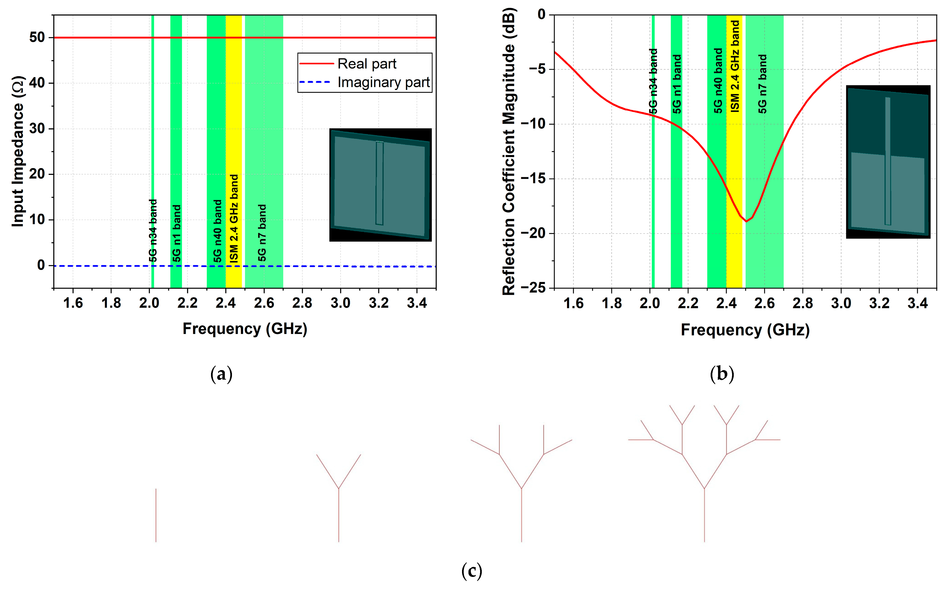
3.1. Flexible Antenna Design, Fabrication, and Testing

According to the flowchart in Figure 1, we initially designed a fractal antenna on an eco-friendly substrate from natural rubber and RHA, aside from the rectifier. Figure 2 illustrates the configuration of the proposed compact and flexible antenna, which comprises a fractal monopole fed with a coplanar waveguide (CPW). In the first step of the design process, we developed a numerical model of the CPW transmission line on the eco-friendly substrate (Figure 3a). Then, we carefully optimized it to provide an optimal balance between compact size and a characteristic impedance of approximately 50 Ω (±5%) within the targeted frequency bands. In the next step, we designed and optimized a monopole antenna (Figure 3b) chosen for its simple structure and wide operational bandwidth. Then, we used the symmetric binary fractal tree to enhance the antenna bandwidth, minimize the antenna dimensions [34], and achieve a more esthetic and unobtrusive design. Figure 3c shows the stages of forming the final fractal binary tree antenna with three branches. In the first stage, we used a vertical segment representing a monopole (parent branch). Next, we created two child branches at a 30° elevation angle from the parent, each with a length scaled to 75% of the parent branch. We repeated this branching pattern two more times, with each new branch separated by a 30° angle and scaled to 75% of the length of the previous branch. After that, via FDTD-based numerical simulations, as outlined in Section 2.3, we optimize the geometric dimensions of the fractal tree and the coplanar waveguide to achieve optimal bandwidth and radiation efficiency in target frequency bands.
Figure 4 presents the antenna reflection coefficient magnitude, radiation efficiency, and gain obtained from the FDTD simulations. The results demonstrate that the optimized antenna design achieves excellent impedance matching with |S11| < −10 dB across a wide bandwidth from 2 GHz to 2.92 GHz, encompassing the targeted 5G and ISM frequency bands. Moreover, from numerically estimated results for efficiency and gain shown in Figure 4b, we can see that the antenna maintains a high radiation efficiency of 95% and stable gain (of about 2.2 dBi) across the operating-frequency range. Figure 5 illustrates the antenna 3D radiation patterns at 2.1 GHz, 2.5 GHz, and 2.9 GHz. From the results, we can observe that the antenna maintains an omnidirectional radiation pattern in the azimuth plane, enabling it to effectively receive signals from almost all directions. Moreover, due to the fractal geometry, the proposed antenna also supports dual linear polarization, which enhances its ability to harvest ambient RF energy regardless of electromagnetic waves’ polarization. Dual linear polarization is particularly beneficial in real-world environments where polarization mismatch can significantly degrade performance.
We fabricated a prototype, employing the methodology detailed in [35] to evaluate the antenna performance and validate the simulation results. The fractal tree and CPW were realized with 0.05 mm brass foil, while the flexible, eco-friendly substrate consisted of a 1.5 mm-thick natural rubber composite reinforced with RHA. For measurement purposes, a coaxial cable with a U.FL connector was soldered to the CPW, as illustrated by the photograph of the fabricated antenna prototype in Figure 6.
Figure 7 shows the measured |S11| of the antenna prototype. The measured impedance bandwidth (|S11| < −10 dB) spans from 2.2 GHz to 3.2 GHz, demonstrating good agreement with the simulation results. The observed slight frequency shift of approximately 0.2 GHz is probably attributable to parasitic effects from the coaxial cable and U.FL connector soldering, the addition of glue, or minor variations in substrate thickness and material properties during fabrication.
Finally, we perform a comparative performance analysis between the proposed flexible antenna and earlier reported flexible antennas to highlight its advantages. Table 3 summarizes the key parameters of recent flexible antennas considered in the comparison. The results indicate that the proposed antenna achieves the highest radiation efficiency at 2.45 GHz (96.7%) among all considered designs, surpassing the closest result in [33] (95%) while maintaining a more compact size (50 × 60 mm). Furthermore, the proposed antenna offers a broad operational bandwidth of 2.0–2.92 GHz, making it ideal for RF energy harvesting across various frequency bands. In contrast, most other designs [23,29,36,37,38,39] are limited to a narrower bandwidth around 2.4–2.5 GHz. Additionally, the proposed antenna used biodegradable and eco-friendly materials for its substrate—specifically, a composite of natural rubber and rice husk ash (RHA)—in alignment with current trends in sustainable and eco-friendly electronics. Compared to other sustainable designs [29,33,36,37,39], it demonstrates significantly higher radiation efficiency (96.7%), which is important for effective RF energy harvesting. Table 3 shows that most other sustainable designs [29,33,36,37,39] exhibit notably lower efficiency, with values as low as 28% in [37], 30.5% in [39], and 53.89% in [29]. Finally, incorporating a symmetric binary fractal tree geometry in the antenna design contributes to miniaturization and an esthetic antenna, an advantage not reported in previous works.

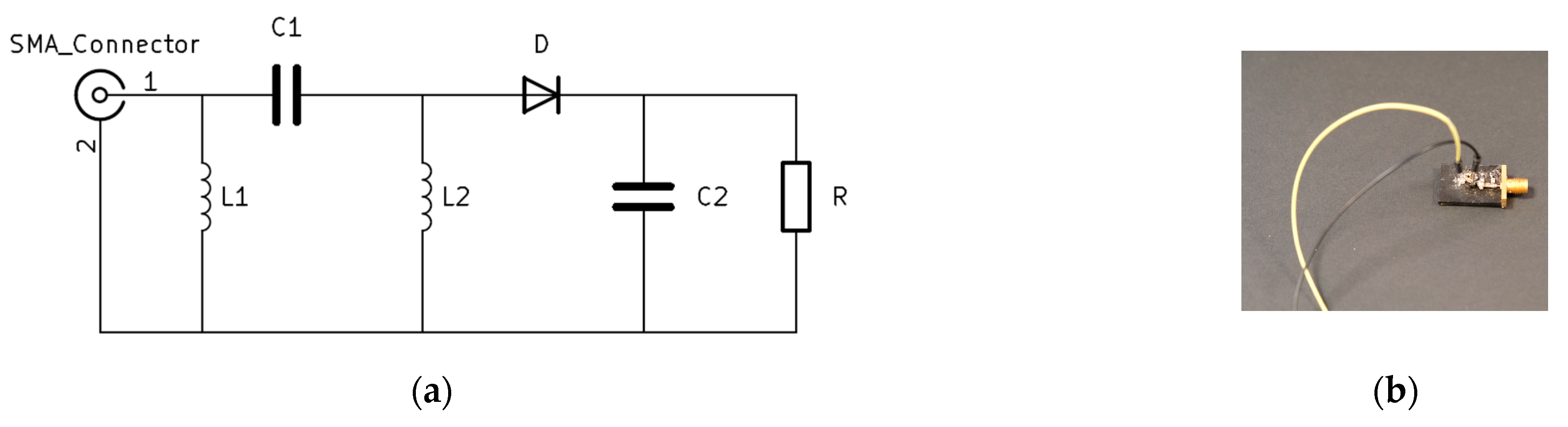
3.2. Design, Fabrication, and Testing of the Rectifier

We designed and implemented a single-series rectifier circuit based on NSVR351SDSA3 Schottky diode to harvest energy from ambient RF fields in target bandwidths. We adopted a single-series diode configuration due to its balance of low complexity, reduced cost, and reliable RF-to-DC conversion performance [40]. After that, we design a matching network to achieve maximum output DC power [41]. To find the final values of the matching network elements, we adopt an iterative optimization process that combines electromagnetic simulations with prototype measurements [25]. This methodology allows the design to meet performance requirements and reduce the influences of the parasitic effects of the SMD components used in the circuit. The schematic of the circuit and a photograph of the fabricated prototype are depicted in Figure 8.
We evaluated the rectifier RF-to-DC conversion efficiency (ηrectifier), connecting the fabricated prototype to the AS108 signal generator, as shown in Figure 9. We measured the DC voltage across four different load resistances (51 Ω, 510 Ω, 1000 Ω, and 4999 Ω) as a function of frequency, with RF input power levels ranging from −15 dBm to +15 dBm. The corresponding RF-to-DC conversion efficiency values, calculated using the formula (1) provided below, are illustrated in Figure 10.
ηrectifier = (PDC/Pin) × 100,
where Pin is the input RF power from the AS108 signal generator in W, and PDC is the output DC power calculated from (2):
PDC = V2DC/RL,
where VDC is measured DC voltage, and RL is the load resistance in Ω.
Figure 10 shows that the rectifier RF-to-DC conversion efficiency increases with the input RF power level. Furthermore, within the frequency range of 2 to 2.6 GHz, the efficiency exhibits an increasing trend with frequency. Beyond 2.6 GHz, a decrease in efficiency is observed with increasing frequency. Figure 10b also shows that the rectifiers achieve a maximum RF-to-DC conversion efficiency of 45.49% at 2.5 GHz for an RF input power of 15 dBm and a load resistance of 510 Ω. As observed, the conversion efficiency exceeded 40%, 30%, 20%, and 5% across the targeted frequency band (2.1–2.7 GHz) at input power levels of 15 dBm, 10 dBm, 0 dBm, and −5 dBm, respectively.

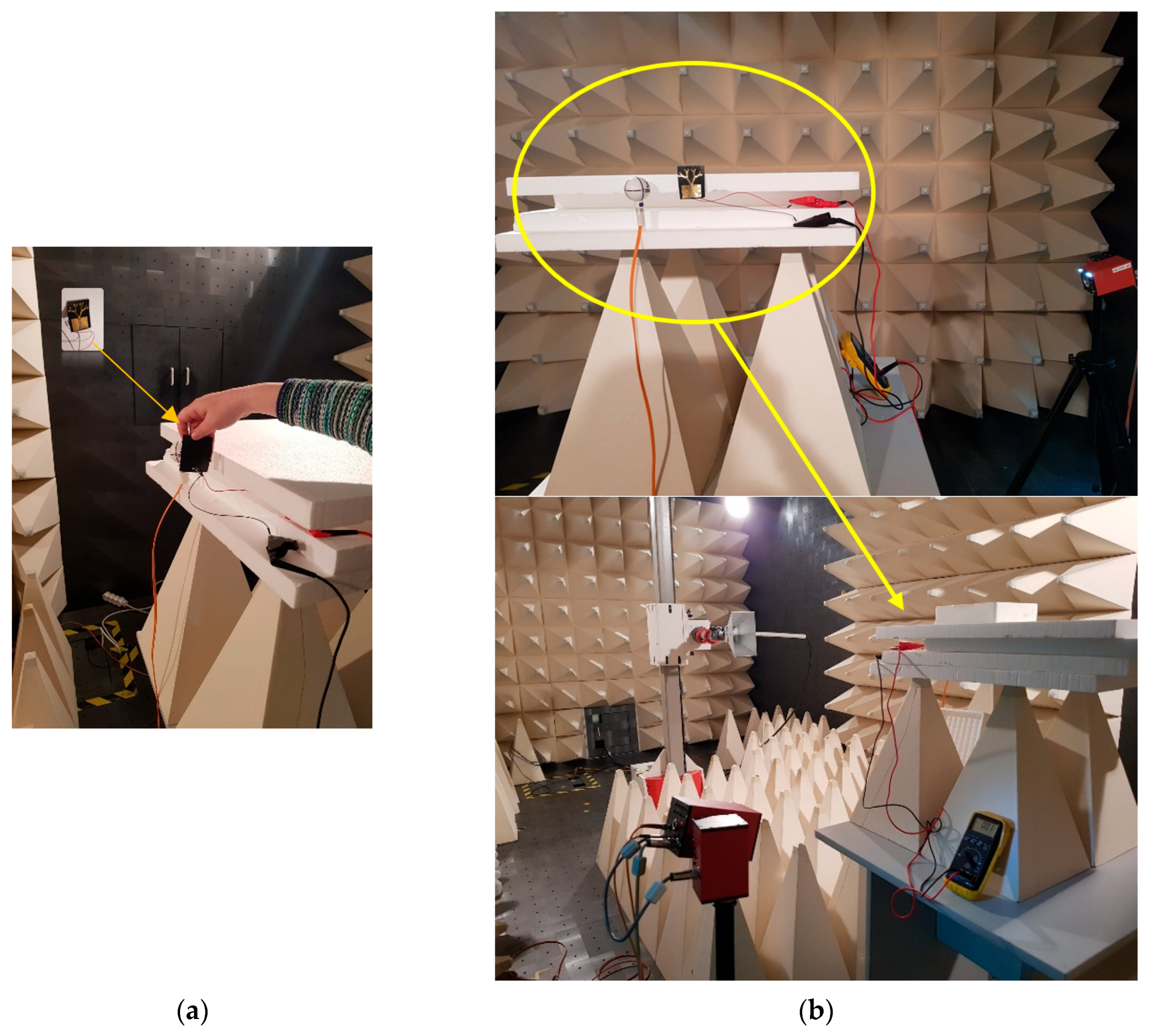
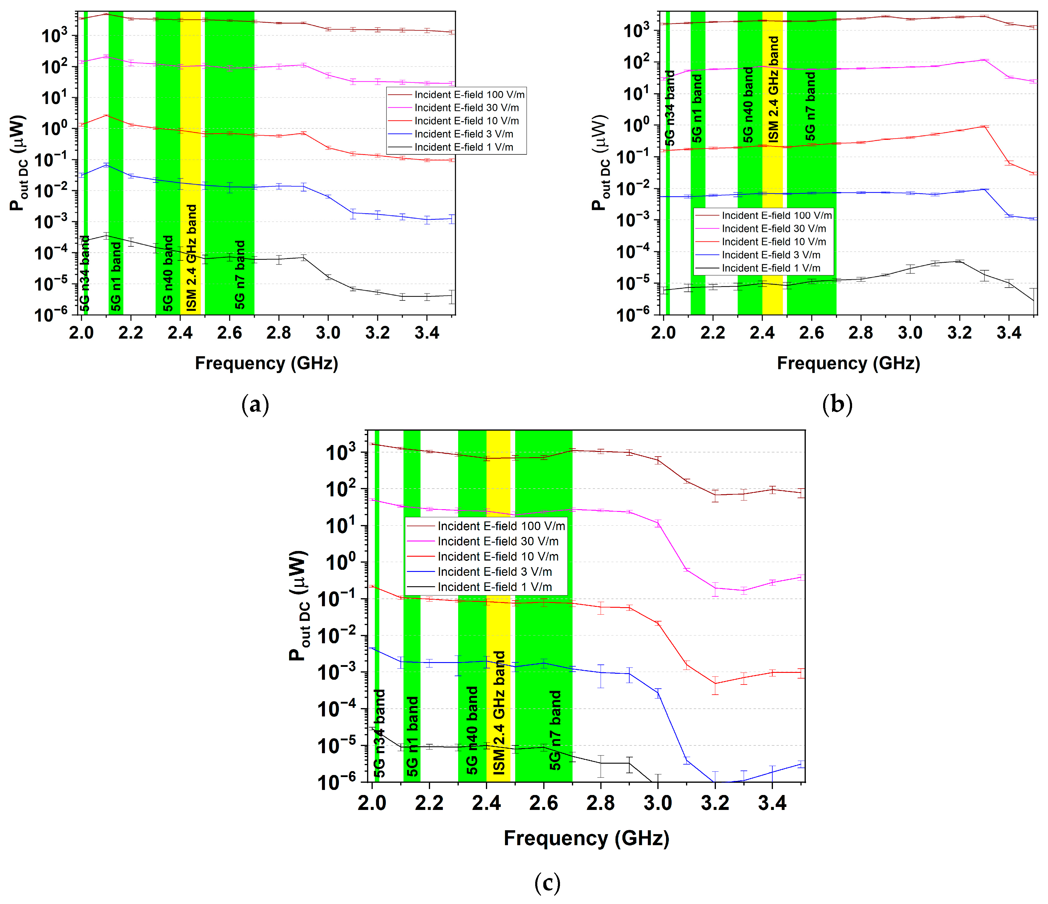
3.3. Rectenna: Fabrication and Testing

To investigate the performance of the rectenna (antenna and rectifier), we integrated the optimized fractal antenna with the rectifier, as shown in Figure 11. To evaluate the performance of the rectenna, we placed the fabricated prototype inside a semi-anechoic chamber at a distance of 1.5 m from a horizontally oriented horn antenna, as illustrated in Figure 11b. We connected the horn antenna to a power amplifier and a signal generator (located outside the semi-anechoic chamber). After that, we measured the DC voltage across the load using a voltmeter in the frequency range of 2.1 to 3.5 GHz for five intensities of the incident electric field (1 V/m, 3 V/m, 10 V/m, 30 V/m, and 100 V/m). We used an isotropic field probe to adjust and continuously monitor the electric field intensity in the plane of the rectenna, ensuring consistent testing conditions. To assess the sensitivity of the rectenna to variations in the orientation of the incident electromagnetic field, we repeated all measurements with the horn antenna oriented vertically and swept at an angle of 45°.
We selected electric field intensities of 10 V/m and 30 V/m to test the rectenna under realistic exposure conditions corresponding to various real-world wireless communication scenarios. For example, peak values of up to 11 V/m have been reported during IEEE 802.11n uplink transmissions [42] in an indoor environment. Inside vehicles, the electric field during GSM voice calls and 5G data transmissions exceeded 20 V/m [43]. For LTE, approximately 10 V/m are observed [44]. Also, in situ measurement of a car cabin during travel shows a maximum electric field intensity of 17 V/m [45]. Moreover, in microwave wireless power transfer systems, the electric field intensity can exceed 100 V/m [46].
Figure 12 presents the output DC power (Pout DC), derived from the measured DC voltage at the rectenna output, as a function of frequency for five electric field intensities under different polarizations. It can be seen that the highest DC power of 4000 μW is obtained at the rectenna output when the intensity of the electric field is 100 V/m at the vertical orientation of the horn antenna. We can find from Figure 12b,c that when the transmitting horn antenna is in horizontal orientation or swept at an angle of 45°, the highest DC power in the target frequency band (2.1 GHz–2.7 GHz) is 2000 μW at 100 V/m. Also, across the targeted frequency band, for the three orientations of the horn antenna, the obtained DC powers are 100 μW, 80 μW, and 50 μW, respectively, when the electric field intensity becomes 30 V/m. From the results, we can conclude that the rectenna can effectively receive signals from all directions over the frequency bandwidth of interest, making it suitable for wireless power transfer and energy-harvesting applications. Moreover, the standard deviations remained consistently low across all measurement points, confirming the excellent reproducibility of the results. This high level of repeatability is attributed to the precision of the experimental setup and the controlled conditions provided by the use of an anechoic chamber.
We also evaluated the rectenna performance in an indoor environment. For this purpose, we selected a residential apartment as a representative ambient indoor setting, featuring a ceiling height of approximately 2.5 m and a total area of around 50 m2. First, we measured the DC voltage at the output of the rectenna versus distance for a frequency of 2.45 GHz using a microwave generator and a dipole antenna in vertical orientation, as shown in Figure 13a. Figure 13b presents the output DC power (Pout DC), derived from the measured DC voltage at the rectenna output, as a function of distance. As expected, the Pout DC average received power (solid line) demonstrates an approximate exponential decay with increasing distance. The graphs also illustrate superimposed periodic fluctuations, primarily resulting from constructive and destructive interference that creates standing wave patterns due to wall reflections. The observed variations are also consistent with the effects of Fresnel zones, which arise due to constructive and destructive interference of electromagnetic waves in the radiative near-field and intermediate-field regions. Moreover, the data suggest that at distances greater than 70 mm, the received power approaches negligible levels.
Additionally, we evaluated the rectenna performance in a real use case scenario, harvesting energy from a nearby Wi-Fi router (ASUS ZenWiFi Pro ET12, ASUSTek Computer Inc., Taipei City, Taiwan) at the same distances as with the microwave generator. In this setup, the DC output voltage of the rectenna was measured as a function of distance from the router, while a 4K Netflix movie was being streamed on a television connected to the router via Wi-Fi, as shown in Figure 14a. From Figure 14b, we can see that environmental factors (especially router traffic) heavily influence output. The high standard deviation observed in PoutDC measurements is closely associated with fluctuations in Wi-Fi router traffic, such as packet bursts during 4K streaming. When the router transmits high-density packets, for instance, while streaming 4K video, the rectenna can harvest more energy. Conversely, during idle periods, the output diminishes. Therefore, we can conclude that variable data transmission has a substantial effect on rectenna performance.

3.4. Practical Use Cases of the Proposed Rectenna

The proposed compact rectenna is particularly well suited for low-power wireless systems. Its unobtrusive design, compact form factor, planar structure, flexibility, low cost, and good performance allow integration across a wide area of practical use cases, including the following:
-
Integrated into sensor nodes in smart homes, environmental monitoring, or precision agriculture. These nodes can function in passive mode, harvesting energy from nearby Wi-Fi routers or cellular base stations, thus eliminating the need for batteries.
-
Integrated into wearable devices. The rectenna can be embedded into garments or accessories to harvest energy from ambient RF fields for powering low-energy devices, such as biometric sensors and fitness trackers.
-
Integrated into passive tracking tags, enabling battery-free operation by scavenging RF energy from nearby readers or ambient signals for logistics systems.

4. Conclusions

In conclusion, we have proposed and experimentally demonstrated a compact, flexible, omnidirectional rectenna suitable for wireless energy harvesting and wireless power transfer of the next-generation ultra-low power IoT devices and wearable electronics, particularly those that require biodegradable and eco-friendly materials. The proposed rectenna can effectively receive signals from all directions over the broad frequency bandwidth, including 5G lower mid-band—2.3 GHz and 2.6 GHz—and ISM 2.4 GHz. Moreover, this article also presents the methodology for designing, optimizing, and fabricating the flexible rectenna for RF energy harvesting. The proposed flexible antenna presents several advantages over similar designs documented in the literature. Foremost among these is its capability to achieve a wide operating bandwidth while maintaining compact dimensions, ensuring coverage across multiple communication standards. A key performance highlight is the antenna’s high radiation efficiency, exceeding 95% within the operating bandwidth. Furthermore, the design introduces a novel application of symmetric binary fractal tree geometry, effectively reducing the overall size and enhancing visual integration, resulting in a more esthetic and less obtrusive design.

Author Contributions

Conceptualization, N.A., B.A. and G.A.; methodology, N.A., B.A. and G.A.; software, N.A. and B.A.; validation, N.A., B.A. and G.A.; formal analysis, N.A. and G.A.; investigation, N.A., B.A. and G.A.; resources, N.A. and G.A.; data curation N.A., B.A. and G.A.; writing—original draft preparation, G.A.; writing—review and editing, N.A. and B.A.; visualization, B.A. and N.A.; supervision, G.A.; project administration, G.A.; funding acquisition, G.A. and N.A. All authors have read and agreed to the published version of the manuscript.

Funding

This research was funded by the BULGARIAN NATIONAL SCIENCE FUND at the Ministry of Education and Science, Bulgaria, grant number KP-06-H57/11 from 16 November 2021 “Antenna structures for new energy sources in next-generation wireless networks”.

Institutional Review Board Statement

Not applicable.

Informed Consent Statement

Not applicable.

Data Availability Statement

The data presented in this study are available on request from the authors.

Conflicts of Interest

The authors declare no conflicts of interest.

Abbreviations

The following abbreviations are used in this manuscript:
IoTInternet of Things
RFRadio Frequency
ISMIndustrial, Scientific, and Medical frequency bands
EMFsElectromagnetic fields
GSMGlobal System for Mobile Communications
UMTSUniversal Mobile Telecommunications System
LTELong Term Evolution
5GFifth Generation
IEEEInstitute of Electrical and Electronics Engineers
RHARice Husk Ash
FDTDFinite-Difference Time-Domain
CPWCoplanar Waveguide
DCDirect Current

References

  1. IoT Analytics. State of IoT 2024: Number of Connected IoT Devices Growing 13% to 18.8 Billion Globally. Available online: https://iot-analytics.com/number-connected-iot-devices/ (accessed on 3 September 2024).
  2. Sooriarachchi, V.P.; Perera, T.D.P.; Jayakody, D.N.K. Ambient Backscatter- and Simultaneous Wireless Information and Power Transfer-Enabled Switch for Indoor Internet of Things Systems. Appl. Sci. 2025, 15, 478. [Google Scholar] [CrossRef]
  3. Rahmani, H.; Basiri, M.; Mirjalili, S.; Jha, N.K.; Razaque, A.; Bolic, M.; Shubair, R.M. Next-Generation IoT Devices: Sustainable Eco-Friendly Manufacturing, Energy Harvesting, and Wireless Connectivity. IEEE J. Microw. 2023, 3, 237–255. [Google Scholar] [CrossRef]
  4. Sherazi, H.H.R.; Zorbas, D.; O’Flynn, B. A Comprehensive Survey on RF Energy Harvesting: Applications and Performance Determinants. Sensors 2022, 22, 2990. [Google Scholar] [CrossRef] [PubMed]
  5. Niotaki, K.; Borges Carvalho, N.; Georgiadis, A.; Gu, X.; Hemour, S.; Wu, K.; Matos, D.; Belo, D.; Pereira, R.; Figueiredo, R.; et al. RF Energy Harvesting and Wireless Power Transfer for Energy Autonomous Wireless Devices and RFIDs. IEEE J. Microw. 2023, 3, 763–782. [Google Scholar] [CrossRef]
  6. Moloudian, G.; Roshani, S.; Roshani, S.; Abdolali, A.; Mohammadi, A. RF Energy Harvesting Techniques for Battery-Less Wireless Sensing, Industry 4.0, and Internet of Things: A Review. IEEE Sens. J. 2024, 24, 5732–5745. [Google Scholar] [CrossRef]
  7. Bougas, I.D.; Papadopoulou, M.S.; Boursianis, A.D.; Kokkinidis, K.; Goudos, S.K. State-of-the-Art Techniques in RF Energy Harvesting Circuits. Telecom 2021, 2, 369–389. [Google Scholar] [CrossRef]
  8. Afridi, A.; Hameed, I.; Koo, I. Quantum PSO-Based Optimization of Secured IRS-Assisted Wireless-Powered IoT Networks. Appl. Sci. 2024, 14, 11677. [Google Scholar] [CrossRef]
  9. Atanasov, B.; Atanasov, N.; Atanasova, G. A Multi-Band Antenna with an Aesthetic Design for Ambient RF Energy Harvesting. In Proceedings of the 17th European Conference on Antennas and Propagation (EuCAP), Florence, Italy, 26–31 March 2023. [Google Scholar]
  10. Kim, S.; Vyas, R.; Bito, J.; Niotaki, K.; Collado, A.; Georgiadis, A.; Tentzeris, M.M. Ambient RF Energy-Harvesting Technologies for Self-Sustainable Standalone Wireless Sensor Platforms. Proc. IEEE 2014, 102, 1649–1666. [Google Scholar] [CrossRef]
  11. Alex-Amor, A.; Moreno-Núñez, J.; Fernández-González, J.M.; Padilla, P.; Esteban, J. Parasitics Impact on the Performance of Rectifier Circuits in Sensing RF Energy Harvesting. Sensors 2019, 19, 4939. [Google Scholar] [CrossRef]
  12. ISO/IEC/IEEE 8802-11:2022; Telecommunications and Information Exchange between Systems—Specific Requirements for Local and Metropolitan Area Networks—Part 11: Wireless LAN Medium Access Control (MAC) and Physical Layer (PHY) Specifications. ISO/IEC/IEEE: Geneva, Switzerland, 2022.
  13. IEEE Std 802.15.1-2005 (Revision of IEEE Std 802.15.1-2002); IEEE Standard for Information Technology—Local and Metropolitan Area Networks—Specific Requirements—Part 15.1a: Wireless Medium Access Control (MAC) and Physical Layer (PHY) Specifications for Wireless Personal Area Networks (WPANs). Institute of Electrical and Electronics Engineers: New York, NY, USA, 2005. [CrossRef]
  14. ISO/IEC/IEEE 8802-15-4:2024; Information Technology—Telecommunications and Information Exchange between Systems—Local and Metropolitan Area Networks—Specific Requirements—Part 15-4: Wireless Medium Access Control (MAC) and Physical Layer (PHY) Specifications for Low-Rate Wireless Personal Area Networks (WPANs). ISO/IEC/IEEE: Geneva, Switzerland, 2024.
  15. ISO/IEC/IEEE 8802-15-6:2017; Information Technology—Telecommunications and Information Exchange between Systems—Local and Metropolitan Area Networks—Specific Requirements—Part 15-6: Wireless Body Area Networks. ISO/IEC/IEEE: Geneva, Switzerland, 2017.
  16. Prashad, L.; Mohanta, H.C.; Mohamed, H.G. A Compact Circular Rectenna for RF-Energy Harvesting at ISM Band. Micromachines 2023, 14, 825. [Google Scholar] [CrossRef] [PubMed]
  17. Awais, Q.; Jin, Y.; Chattha, H.T.; Jamil, M.; Qiang, H.; Khawaja, B.A. A compact rectenna system with high conversion efficiency for wireless energy harvesting. IEEE Access 2018, 6, 35857–35866. [Google Scholar] [CrossRef]
  18. Ojha, S.S.; Sharma, J.K.; Dhakad, B.; Kumar, S.; Sharma, N.; Pandey, A.K.; Hasnain, S.M.; Kumar, S.; Kumar, R. A dual ultra-wideband rectenna with a compact conical antenna for RF energy harvesting from S and C bands. Results Eng. 2024, 22, 102279. [Google Scholar] [CrossRef]
  19. Sidibe, A.; Takacs, A.; Loubet, G.; Dragomirescu, D. Compact Antenna in 3D Configuration for Rectenna Wireless Power Transmission Applications. Sensors 2021, 21, 3193. [Google Scholar] [CrossRef] [PubMed]
  20. Khang, S.-T.; Yu, J.W.; Lee, W.-S. Compact folded dipole rectenna with RF-based energy harvesting for IoT smart sensors. Electron. Lett. 2015, 51, 926–928. [Google Scholar] [CrossRef]
  21. Zhang, X.; Cao, C.; Song, C. A compact dual-band dual-circular-polarization wideband rectenna using reverse Wilkinson power divider for wireless information and power transfer. IEEE Antennas Wirel. Propag. Lett. 2024, 23, 2728–2732. [Google Scholar] [CrossRef]
  22. Benkalfate, C.; Ouslimani, A.; Kasbari, A.-E.; Feham, M. A New Compact Triple-Band Triangular Patch Antenna for RF Energy Harvesting Applications in IoT Devices. Sensors 2022, 22, 8009. [Google Scholar] [CrossRef]
  23. Adami, S.-E.; Proynov, P.; Hilton, G.S.; Yang, G.; Zhang, C.; Zhu, D. A flexible 2.45-GHz power harvesting wristband with net system output from −24.3 dBm of RF power. IEEE Trans. Microw. Theory Tech. 2018, 66, 380–395. [Google Scholar] [CrossRef]
  24. Du, C.-H.; Cheng, F.; Yang, Y.; Zhu, H.; Gu, C. Omnidirectional flexible tri-band rectenna with eliminated matching circuit for ambient RF energy harvesting. IEEE Trans. Microw. Theory Tech. 2025, 73, 674–686. [Google Scholar] [CrossRef]
  25. Wagih, M.; Weddell, A.S.; Beeby, S. High-Efficiency Sub-1 GHz Flexible Compact Rectenna based on Parametric Antenna-Rectifier Co-Design. In Proceedings of the 2020 IEEE/MTT-S International Microwave Symposium (IMS), Los Angeles, CA, USA, 4–6 August 2020; pp. 1066–1069. [Google Scholar]
  26. Al-Sehemi, A.; Al-Ghamdi, A.; Dishovsky, N.; Atanasova, G.; Atanasov, N. A Flexible Multiband Antenna for Biomedical Telemetry. IETE J. Res. 2020, 66, 1006–1014. [Google Scholar] [CrossRef]
  27. Silva, M.J.; Claro, P.I.C.; da Silva, J.C.; Scaloppi Júnior, E.J.; Gonçalves, P.S.; Martins, M.A.; Mattoso, L.H.C. Evaluation of the physicochemical properties of natural rubber from Hevea brasiliensis clones. Ind. Crops Prod. 2021, 171, 113906. [Google Scholar] [CrossRef]
  28. Arayapranee, W.; Na-Ranong, N.; Rempel, G.L. Application of rice husk ash as fillers in the natural rubber industry. J. Appl. Polym. Sci. 2005, 98, 34–41. [Google Scholar] [CrossRef]
  29. Al-Sehemi, A.; Al-Ghamdi, A.; Dishovsky, N.; Atanasov, N.; Atanasova, G. Rubber composites based on renewable resources and their potential for application in flexible wearable antennas. Iran. Polym. J. 2022, 31, 1117–1127. [Google Scholar] [CrossRef]
  30. The Circular Economy of Brass Recycling. Available online: https://highspeedmachiningbrass.com/the-circular-economy-of-brass-recycling/ (accessed on 1 March 2020).
  31. Taflove, A.; Hagness, S.C. Computational Electrodynamics: The Finite-Difference Time-Domain Method, 3rd ed.; Artech House: Norwood, MA, USA, 2005; pp. 607–676. [Google Scholar]
  32. Atanasov, N.T.; Atanasov, B.N.; Atanasova, G.L. Electromagnetic Properties of Natural Plant Leaves for Eco-Friendly and Biodegradable Substrates for Wireless IoT Devices. Sensors 2025, 25, 1118. [Google Scholar] [CrossRef] [PubMed]
  33. Al-Sehemi, A.; Al-Ghamdi, A.; Dishovsky, N.; Atanasova, G.; Atanasov, N. Flexible polymer/fabric fractal monopole antenna for wideband applications. IET Microw. Antennas Propag. 2021, 15, 80–92. [Google Scholar] [CrossRef]
  34. Zang, H.; Zhao, X.; Xu, X.; Zhang, G.; Lu, J. A Review of Fractal Tree Antennas. In Proceedings of the 2014 International Conference on Future Computer and Communication Engineering, Dalian, China, 21–22 March 2014; pp. 15–18. [Google Scholar]
  35. Al-Sehemi, A.; Al-Ghamdi, A.; Dishovsky, N.; Atanasov, N.; Atanasova, G. A Flexible Miniature Antenna for Body-Worn Devices: Design and Transmission Performance. Micromachines 2023, 14, 514. [Google Scholar] [CrossRef]
  36. Kanaparthi, S.; Sekhar, V.R.; Badhulika, S. Flexible, eco-friendly and highly sensitive paper antenna based electromechanical sensor for wireless human motion detection and structural health monitoring. Extreme Mech. Lett. 2016, 9, 324–330. [Google Scholar] [CrossRef]
  37. Li, Z.; Sinha, S.K.; Treich, G.M.; Wang, Y.; Yang, Q.; Deshmukh, A.A.; Sotzing, G.A.; Cao, Y. All-organic flexible fabric antenna for wearable electronics. J. Mater. Chem. C 2020, 8, 5662–5667. [Google Scholar] [CrossRef]
  38. Eid, A.; Hester, J.; Nauroze, A.; Lin, T.-H.; Costantine, J.; Tawk, Y.; Ramadan, A.H.; Tentzeris, M. A Flexible Compact Rectenna for 2.4 GHz ISM Energy Harvesting Applications. In Proceedings of the 2018 IEEE International Symposium on Antennas and Propagation and USNC-URSI Radio Science Meeting, Boston, MA, USA, 8–13 July 2018; pp. 1887–1888. [Google Scholar]
  39. Awang, Z.; Affendi, N.A.M.; Alias, N.A.L.; Razali, N.M. Flexible antennas based on natural rubber. Prog. Electromagn. Res. C 2016, 61, 75–90. [Google Scholar] [CrossRef]
  40. Shen, S.; Chiu, C.-Y.; Murch, R.D. Multiport Pixel Rectenna for Ambient RF Energy Harvesting. IEEE Trans. Antennas Propag. 2018, 66, 644–656. [Google Scholar] [CrossRef]
  41. Halimi, M.A.; Khan, T.; Palandoken, M.; Kishk, A.A.; Antar, Y.M.M. Rectifier Design Challenges for Wireless Energy Harvesting/Wireless Power Transfer Systems: Broadening Bandwidth and Extended Input Power Range. IEEE Microw. Mag. 2023, 24, 54–67. [Google Scholar] [CrossRef]
  42. Sârbu, A.; Miclăuș, S.; Digulescu, A.; Bechet, P. Comparative Analysis of User Exposure to the Electromagnetic Radiation Emitted by the Fourth and Fifth Generations of Wi-Fi Communication Devices. Int. J. Environ. Res. Public Health 2020, 17, 8837. [Google Scholar] [CrossRef] [PubMed]
  43. Atanasov, N.T.; Atanasova, G.L.; Gârdan, D.A.; Gârdan, I.P. Experimental Assessment of Electromagnetic Fields Inside a Vehicle for Different Wireless Communication Scenarios: A New Alternative Source of Energy. Energies 2023, 16, 5622. [Google Scholar] [CrossRef]
  44. Kwon, D.; Lee, A.-K.; Choi, H.-D. Spatial Electric Field Distribution near the Base Station Antenna Using Ray Tracing. In Proceedings of the 2017 International Symposium on Antennas and Propagation (ISAP), Phuket, Thailand, 30 October–2 November 2017. [Google Scholar]
  45. Atanasova, G.L.; Atanasov, B.N.; Atanasov, N.T. Assessment of Electromagnetic Field Exposure on European Roads: A Comprehensive In Situ Measurement Campaign. Sensors 2023, 23, 6050. [Google Scholar] [CrossRef] [PubMed]
  46. Li, K.-R.; See, K.-Y.; Koh, W.-J.; Zhang, J.-W. Design of 2.45 GHz Microwave Wireless Power Transfer System for Battery Charging Applications. In Proceedings of the 2017 Progress in Electromagnetics Research Symposium—Fall (PIERS-FALL), Singapore, 19–22 November 2017. [Google Scholar]
Figure 1. Flowchart of the rectenna design, optimization, fabrication, and testing methodology.
Applsci 15 06303 g001
Figure 2. Configuration of the proposed antenna. All dimensions are in millimeters.
Applsci 15 06303 g002
Figure 3. Antenna design process: (a) Input impedance and the numerical model of CPW; (b) reflection coefficient magnitude versus frequency and the numerical model of the optimized monopole antenna; (c) stages of forming the final fractal binary tree antenna.
Applsci 15 06303 g003
Figure 4. Simulated: (a) reflection coefficient magnitudes versus frequency; (b) radiation efficiency and maximum gain versus frequency.
Applsci 15 06303 g004
Figure 5. Three-dimensional radiation patterns of the antenna at: (a) 2.1 GHz; (b) 2.5 GHz; (c) 2.9 GHz; and (d) antenna gain scale.
Applsci 15 06303 g005
Figure 6. Photo of the fabricated antenna prototype.
Applsci 15 06303 g006
Figure 7. Measured reflection coefficient magnitude versus frequency.
Applsci 15 06303 g007
Figure 8. Rectifier: (a) schematic of the circuit; (b) photograph of the fabricated prototype. The main circuit parameters are as follows: L1 = 11 nH, L2 = 33 nH, C1 = 1 pF, C2 = 100 pF.
Applsci 15 06303 g008
Figure 9. Photograph of the test setup and fabricated rectifier circuit prototype.
Applsci 15 06303 g009
Figure 10. Rectifier RF-to-DC conversion efficiency at load resistance: (a) 51 Ω; (b) 510 Ω; (c) 1000 Ω; (d) 4999 Ω.
Applsci 15 06303 g010
Figure 11. Fabricated prototype of the rectenna: (a) photograph of the top and back side; (b) photographs of the test setup and prototype inside a semi-anechoic chamber.
Applsci 15 06303 g011
Figure 12. Output DC power (Pout DC) of the rectenna as a function of frequency for five electric field intensities (1 V/m, 3 V/m, 10 V/m, 30 V/m, and 100 V/m) at (a) vertical orientation of the horn antenna; (b) horizontal orientation of the horn antenna; (c) horn antenna swept at an angle of 45°.
Applsci 15 06303 g012
Figure 13. Output DC power (Pout DC) of the rectenna placed on the wall as a function of distance from a microwave generator: (a) photo of the measurement setup; (b) results.
Applsci 15 06303 g013
Figure 14. Output DC power (Pout DC) of the rectenna placed on the wall as a function of distance from a Wi-Fi router: (a) photo of the measurement setup; (b) results.
Applsci 15 06303 g014
Table 1. Target specifications associated with the design goal.
Parameter Specifications
ApplicationFor powering devices with ultra-low power consumption
Operating Frequency5G lower mid-band—n40 and n7—and ISM 2.4 GHz
Bandwidth (GHz)≥0.5
|S11| in operating frequency range (dB)≤−10
Rectifier RF-to-DC Conversion Efficiency (%)≥30
Maximum size (cm2)≤30
Weight (g)≤10 (antenna and rectifier integrated)
Total Thickness (Profile)≤2 mm (antenna and rectifier integrated)
Rectenna MaterialsFlexible, eco-friendly, biodegradable, or recyclable materials
Table 2. Electromagnetic parameters of the substrate numerical model.
Real Part of the Relative PermittivityElectrical Conductivity
(S/m)
Density
(kg/m3)
2.86870.004926700
Table 3. Comparison between the proposed flexible eco-friendly antenna and other sustainable designs.
ReferenceAntenna TypeAntenna Size (mm)Antenna Substrate
Material
Efficiency (%)
at 2.45 GHz
Frequency Band (GHz) at |S11| ≤ −10 dBEco-Friendly
[23]patch70 × 64 × 3.7Polyester felt
Woven polyester
732.4–2.5No
[36]patch29.5 × 37.7PaperNA2.43–2.51Yes
[37]patchNAPEDOT:PSS282.2–2.5Yes
[38]monopole50 × 11.5 × 0.18Liquid crystal polymer40NANo
[39]patch50 × 50 × 1Natural rubber30.52.43–2.5Yes
[29]dipole50 × 40 × 4.6Natural rubber + RHA53.892.4–2.5Yes
[33]monopole58 × 76 × 2Natural rubber + SiO2952.2–6.0Yes
This workmonopole50 × 60 × 2Natural rubber + RHA96.72.0–2.92Yes
Disclaimer/Publisher’s Note: The statements, opinions and data contained in all publications are solely those of the individual author(s) and contributor(s) and not of MDPI and/or the editor(s). MDPI and/or the editor(s) disclaim responsibility for any injury to people or property resulting from any ideas, methods, instructions or products referred to in the content.

