1. Introduction
In the context of increasingly frequent natural and man-made disasters, the deployment of autonomous mobile robotic platforms for emergency response and search-and-rescue (SAR) operations has become a critical focus in robotics research. These systems are required to operate reliably in unstructured, dynamic, and often hazardous environments, where human intervention is limited or unsafe. To support real-world deployment, simulation environments play a pivotal role in the development, testing, and validation of robotic control architectures, localization algorithms, perception systems, and communication strategies under reproducible conditions. The integration of simulation with robotic middleware such as the Robot Operating System (ROS) has led to substantial advancements in the prototyping and verification of mobile robots.
Nieto [
1] highlights the importance of simulation for verifying robotic control applications implemented on resource-constrained hardware, such as FPGAs, emphasizing the need for reproducible and cost-efficient testbeds during early development phases. Similarly, Igarashi [
2] demonstrates the development of an outdoor mobile inverted pendulum robot, emphasizing stability control in unstructured terrain and underscoring the significance of simulation prior to physical deployment. Macenski [
3], in their comprehensive survey on ROS2, reviews modern navigation stacks and perception pipelines, reinforcing the indispensable role of simulation for scalable, modular, and secure robotic architectures.
The importance of accurate robotic modeling in Gazebo/ROS is addressed by Dobrokvashina [
4], who provides a detailed tutorial on building custom mobile robot models, focusing on the physical and visual fidelity of simulation. Chikurtev [
5] presents practical insights into mobile robot navigation using ROS and Gazebo, providing evidence of how simulation supports the iterative development of planning and control algorithms. In the field of autonomous inspection, Abd Rahman [
6] introduced a robotic system for radiological clutter detection, wherein simulation facilitates risk-free optimization of sensor positioning and motion strategies.
Marian [
7] describes a ROS-based control application tested in Gazebo, designed for SAR scenarios, proving the capability of simulation to evaluate real-time teleoperation and terrain traversal. The work of Rivera [
8] focuses on unmanned ground vehicle (UGV) modeling in ROS/Gazebo, emphasizing its use in realistic validation of vehicle dynamics, locomotion control, and mission planning. Kitano’s foundational RoboCup Rescue framework [
9] formalized the simulation domain as a benchmark for large-scale disaster response, highlighting the role of synthetic environments in evaluating autonomous agent performance.
In a more recent development, Raudmäe [
10] proposed ROBOTONT, an open-source ROS-supported omnidirectional robot for education and research, where simulation forms a core part of its test pipeline. Takaya [
11] explored simulation environments for mobile robot testing and demonstrated their necessity for early validation of real-time control loops. Similarly, Dehnavi [
12] proposed a formal method for verifying ROS-based programs through actor-based modeling using the Rebeca framework, showing how simulation ensures correctness before deployment.
Afanasyev [
13] applied SLAM techniques to a Gazebo-simulated robot in an image-based 3D indoor model, illustrating the potential of simulation in perception-intensive scenarios. Worrall [
14] investigates path planning algorithms for urban SAR missions, validating them within simulation environments as a precursor to deployment. Brunner [
15] focuses on motion planning for reconfigurable mobile robots in disaster scenarios, where Gazebo simulation is used to test configuration-specific locomotion strategies. Finally, Gyarmati [
16] reviews contributions to the development of SAR robots, reinforcing the importance of realistic simulation environments for prototyping complex rescue behaviors.
The study by Platt and Ricks [
17] provides a comparative analysis between two prominent simulation frameworks—ROS–Gazebo and ROS–Unity3D—for simulating ground mobile robots. Their findings emphasize differences in realism, extensibility, and integration complexity, offering valuable insight into the trade-offs between physics-based simulation and immersive 3D environments. This type of comparative evaluation is particularly important for researchers and developers when selecting the most appropriate simulation platform for their specific use case, as it directly impacts the accuracy of robotic behavior modeling, the ease of system integration, and the transferability of results to real-world applications. The work of Alajami [
18] presents a ROS-based distributed strategy for localization and orientation within heterogeneous multi-robot systems, highlighting the advantages of decentralized coordination in environments where individual robots may differ in sensing, computation, or mobility capabilities. The primary objective of this study is to simulate the collaborative behavior of multiple mobile robots, demonstrating how distributed algorithms can enable robust and scalable localization in dynamic and diverse scenarios.
Recent literature places significant emphasis on the simulation of mobile robots for emergency scenarios, particularly through ROS and Gazebo-based frameworks [
19,
20,
21,
22,
23,
24,
25,
26,
27]. This simulation-driven approach enables safe testing, algorithm benchmarking, and deployment validation in hazardous environments. Notable contributions in this field explore obstacle avoidance, radiation mapping, LiDAR-based navigation, reinforcement learning, and multi-robot coordination, illustrating the versatility and growing relevance of virtual testing platforms. These works form a foundational basis for advancing robotic resilience in disaster-response missions.
Collectively, these studies confirm that high-fidelity simulation environments, especially those built on ROS and Gazebo, are not only instrumental for algorithm validation and system integration but are also central to the development of resilient, adaptive, and secure robotic solutions. Simulation enables the study of sensoric, manual control, environmental uncertainty, and hardware limitations in a risk-free setting, which is especially crucial for robots designed to operate in time-critical, safety-sensitive domains. Furthermore, simulation allows researchers to benchmark the impact of encryption, communication delays, and cooperative planning strategies in multi-robot systems under realistic mission conditions.
This paper introduces a ROS2/Gazebo-based simulation framework tailored for evaluating mobile robotic behavior in emergency scenarios. The proposed platform incorporates LiDAR-based mapping, trajectory tracking, and map scanning in secure inter-agent communication channels. By integrating sensing, tracking, scanning, and security into a unified simulated framework, this work contributes a reproducible and extensible testbed for studying robotic autonomy under realistic emergency constraints.
In contrast to conventional wheeled robots, which typically rely on rigid chassis structures and standard wheel configurations, the proposed prototype incorporates a significantly more adaptable locomotion system. While traditional wheeled robots perform efficiently on flat terrains, they often exhibit limitations when confronted with irregular surfaces or vertical discontinuities such as stairs.
This design introduces a novel coupling mechanism that enables the front and rear sections of the chassis to move semi-independently. This central passive joint enhances the robot’s ability to conform to uneven ground profiles, improving traction and balance. Furthermore, each leg–wheel locomotion unit integrates four curved limbs that contribute to superior stability during stair climbing and obstacle traversal. This configuration allows for a smoother transition over steps and ledges, outperforming standard wheel systems in unstructured or multi-level environments. This paper focuses on the locomotion of a mobile robot on flat surfaces, aiming to evaluate and validate its basic navigation capabilities, including movement stability, manual control responsiveness, and obstacle detection under planar conditions.
The remainder of this article is structured as follows:
Section 2 introduces the system architecture, detailing the simulation environment in which the robotic components are developed. This section also outlines the integration and communication mechanisms with the Kubernetes cluster, as well as the process of exporting and generating the URDF model from the CAD environment and embedding it into the simulation framework.
Section 3 focuses on the architecture of the simulation subsystem, describing the communication configuration and required ROS2 packages. Additionally, it presents the validation of the URDF model, including aspects related to visual representation, collision geometry, mass distribution, and inertia properties of the robot’s components.
Section 4 presents the simulation of the mobile robot on a flat surface within a customized environment. The robot is equipped with four differential drive controllers for motion control. This section also includes results related to SLAM-based map scanning and the success rate achieved using a single mobile robot.
Section 5 proposes the extension of the system by introducing a second mobile robot, leading to a collaborative mapping strategy that achieved a 100% scan success rate on the first attempt. The final section,
Section 6, presents the conclusions and outlines future research directions, including the secure integration of the simulation environment with other network components, the development of autonomous navigation strategies based on SLAM outputs using Nav2, and the exploration of complex emergency scenarios. These scenarios envision a collaborative response involving two ground robots and one aerial unit operating in a coordinated search and rescue mission.
This paper, which is built upon and is thoroughly documented in the third research report of the doctoral thesis [
19], played a central role in shaping the development of the robotic platform. It contributed significantly to both the mechanical design choices and the formulation of the robot’s kinematic strategy. By grounding the simulation approach in a well-defined theoretical and experimental framework, this paper ensures that the current simulation work is not only technically consistent but also aligned with validated design principles. Furthermore, it establishes a direct link between the foundational design studies and the present implementation in simulated environments, thereby reinforcing the coherence and scientific rigor of the overall research.
2. Architecture and Deployment of the Mobile Robotic Network Developed for Emergency Situations
The virtualized simulation subcomponent of the robotic network architecture involves the creation of emergency response scenarios and the analysis of experimental data. The need for a simulation environment stems from its ability to generate preliminary results through the abstraction of real-world emergency resolution processes.
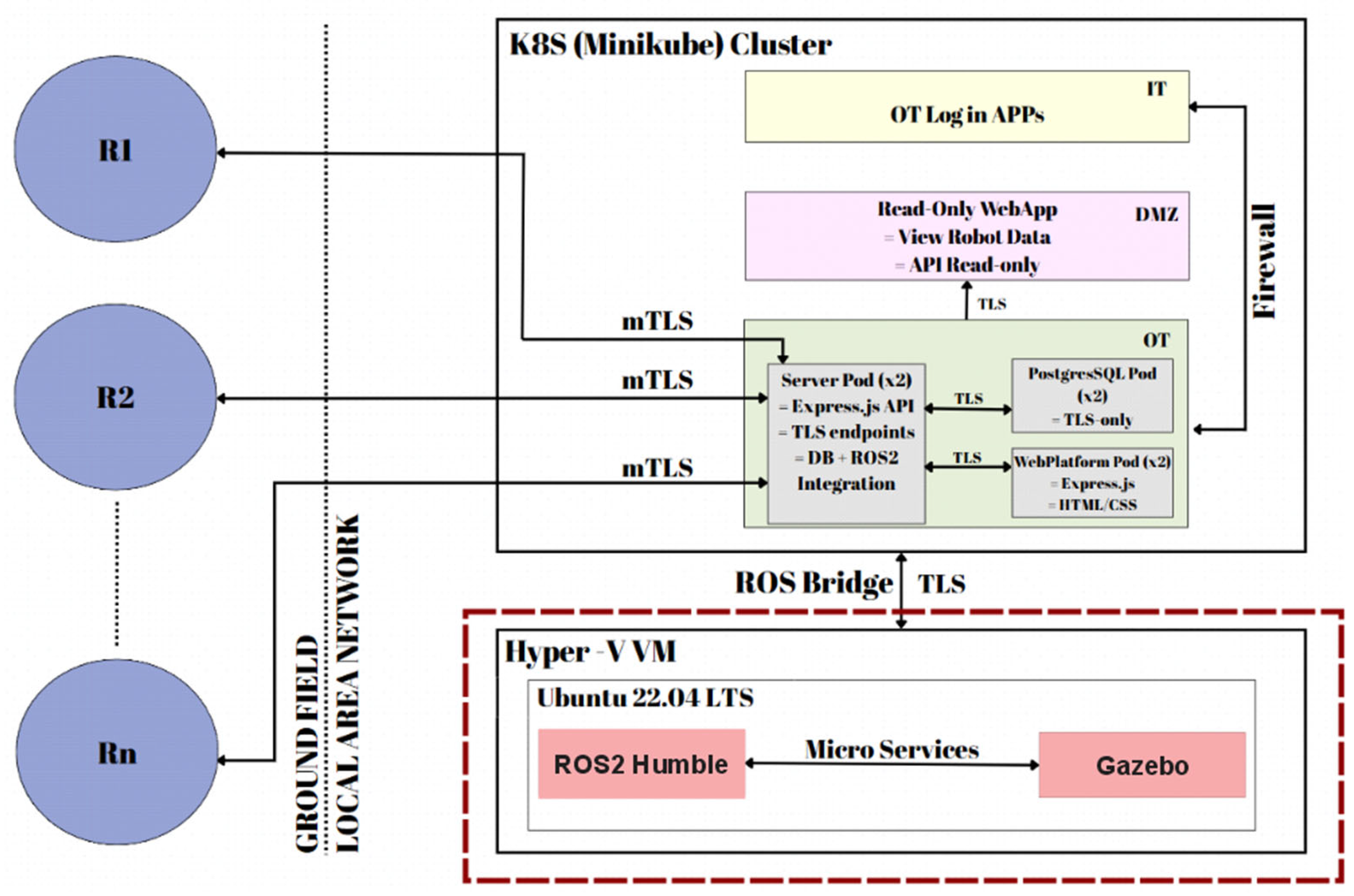
This subcomponent is integrated into the architecture of a mobile robotic network and connects to its central server via a secure TLS communication protocol, implemented in the form of a ROS Bridge.
Figure 1 illustrates the bidirectional link between the robotic network server—deployed within a Kubernetes cluster and simulated using Minikube—and a Hyper-V virtual machine that runs the simulation environment associated with the simulation subcomponent. The Hyper-V virtualization platform was selected to host a virtual machine running Ubuntu 22.04 LTS. Within this environment, ROS2 Humble and the Gazebo simulation framework have been installed and configured. Data exchanged between the virtual machine and the robotic network server are transmitted through ROS2 nodes and topics.
Figure 1 also outlines the broader system architecture, which will be developed in a subsequent research phase. The proposed design leverages Kubernetes-based infrastructure and partitions the network’s components into three distinct security zones: OT (Operational Technology), DMZ (Demilitarized Zone), and IT (Information Technology). Each of these zones hosts critical elements of the robotic network, including the central server, the web platform, and the relational database management system (RDBMS). Furthermore, a Read-Only application is proposed for deployment within the DMZ security zone. The IT zone will be limited to handling user authentication and registration processes, abstracted via web-based applications.
This study focuses on the installation and configuration of the Robot Operating System (ROS) environment alongside the Gazebo simulation framework. In addition, the authors propose the simulation of a locomotion scenario on flat surfaces. The data extracted from the simulation will be transmitted to the Minikube cluster via the WSS protocol, secured using TLS encryption.
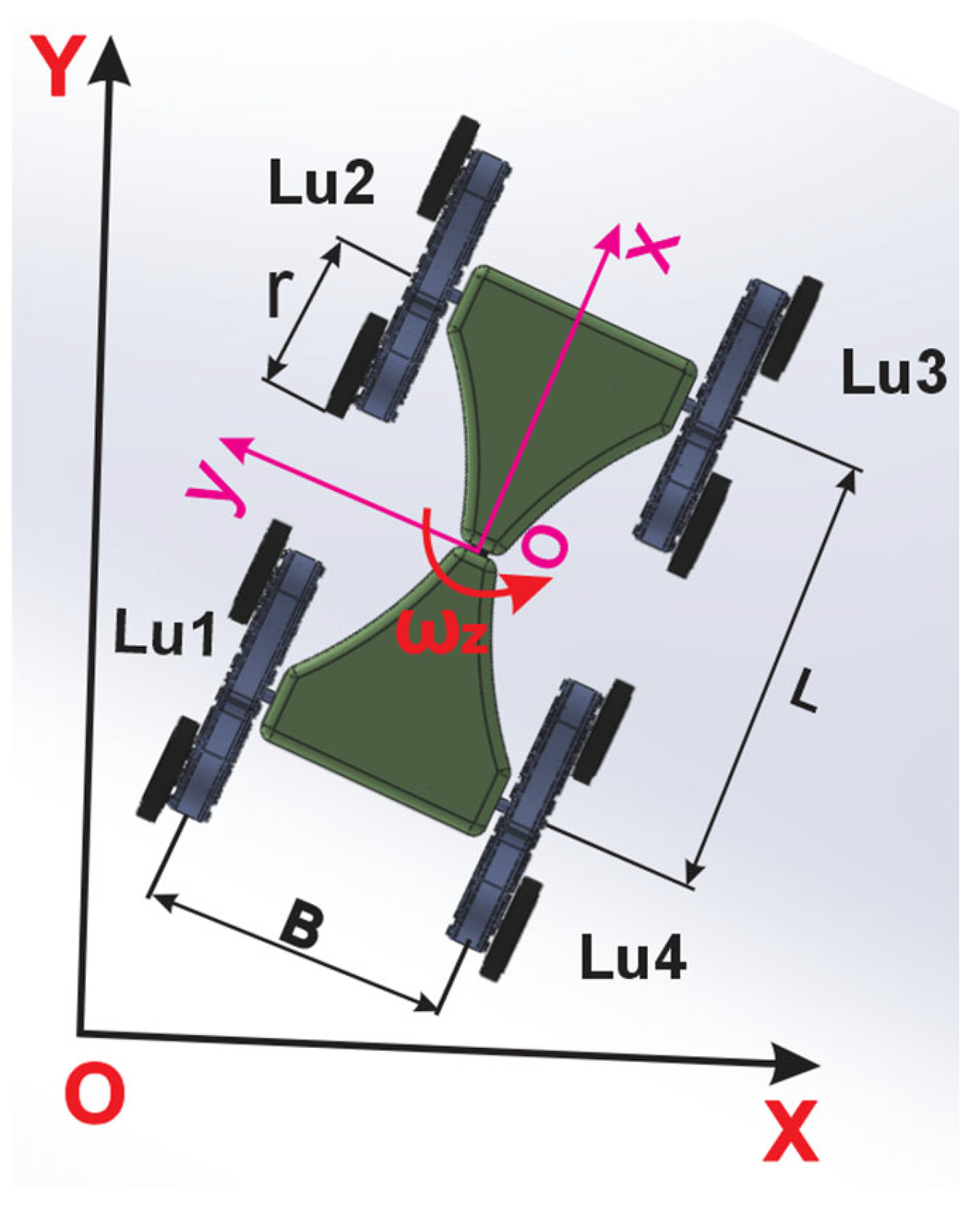
The mathematical modeling of the robot is based on its unique locomotion system, which comprises four leg–wheel units designed for enhanced terrain adaptability, as illustrated in
Figure 2. For the purpose of kinematic analysis, the system is approximated as a four-wheeled skid-steering mobile robot with independent drive units, a common abstraction validated in previous studies [
28,
29]. This approximation relies on the geometric equivalence between the hybrid leg–wheel locomotion units (Lu) and a conventional four-wheel skid-steering robot.
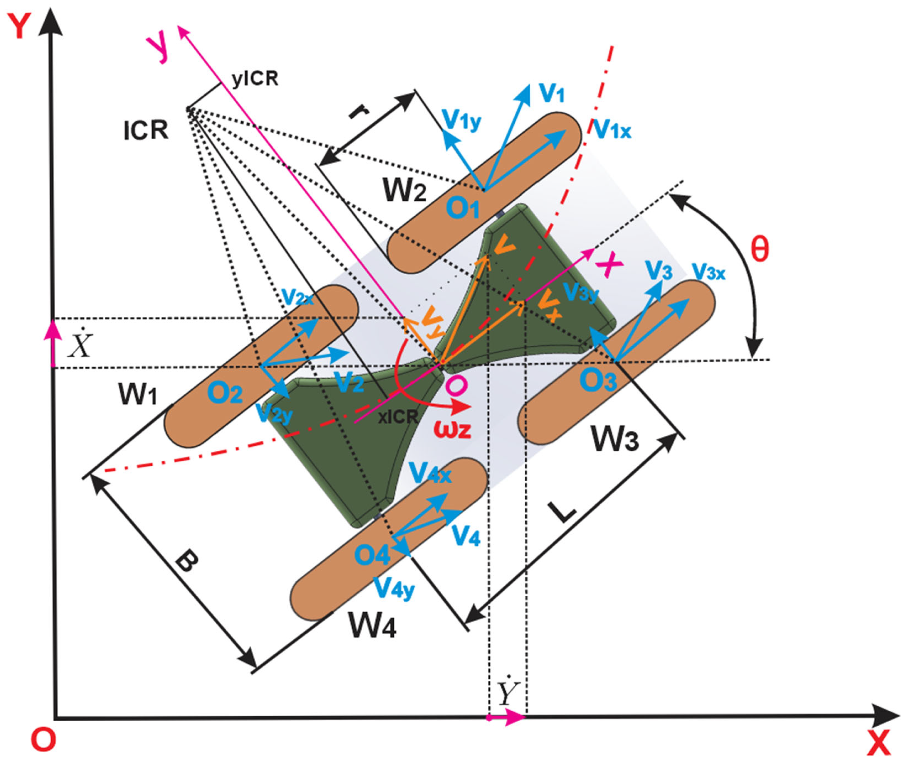
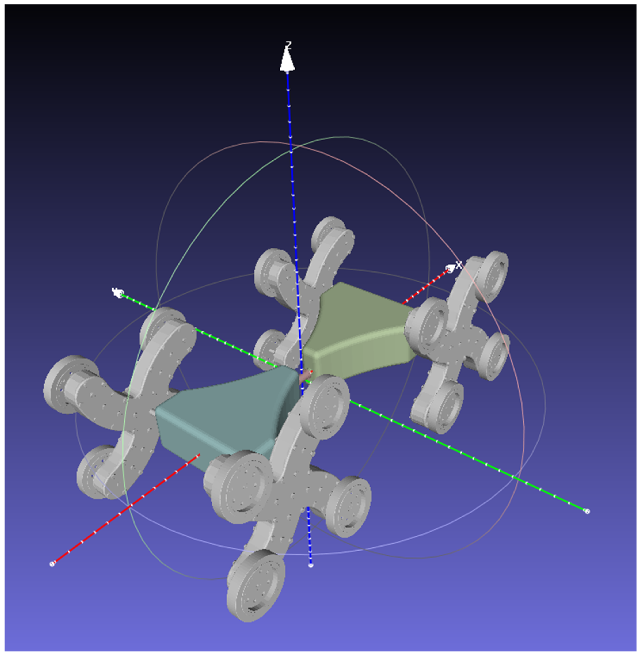
An inertial reference frame (X, Y) noted with black color, also referred to as the global frame, and a body-fixed frame (x, y) noted with violet color attached to the robot are defined, as illustrated in
Figure 3.
This figure also presents the kinematic diagram of a skid-steering mobile robot, under the assumption that the robot’s center of mass coincides with the geometric center of the body frame. Each locomotion unit consists of two extreme wheels that maintain continuous contact with the ground surface. The four extreme wheels, which are in contact with the locomotion surface and located on the same side of the robot, are assumed to rotate at identical angular velocities and have the same angular velocities. For the purpose of kinematic analysis, each leg–wheel locomotion unit is approximated as a single conventional wheel, allowing the system to be modeled as a four-wheeled skid-steering mobile robot, as shown in
Figure 3. The velocities associated with the locomotion unit are described, where the angular velocity of the motor is developing all four
angular velocities through a planetary gear system.
The robot is assumed to operate on a planar surface, where its linear velocity in the local frame is expressed as
= (
,
, 0)
T, and its angular velocity is given by ω = (0, 0, ω
z)
T. The generalized state vector q = (X, Y, θ)
T describes the robot’s pose, including the position of the center of mass in the global frame and the orientation angle θ of the local frame relative to the global one. Consequently, the vector of generalized velocities is q̇ = (ẋ, ẏ,
)
T. The transformation between the velocity components in the local and global coordinate systems can then be derived in a straightforward manner.
The angular velocities of the wheels, denoted by ω
i, where i = 1, 2, 3, 4 correspond to the front-left, rear-left, front-right, and rear-right wheels, respectively. According to the second modeling assumption, the wheels on each side of the robot are constrained to rotate at the same angular speed, leading to the following conditions:
Based on these assumptions, the forward kinematic model of the robot on a planar surface can be expressed as follows [
28]:
where
= (
,
) is the robot’s translational velocity with respect to its local frame, ω
z is its angular velocity, and r is the radius of the wheel.
To fully define the kinematic model of the mobile robot, it is necessary to consider additional velocity components relative to the inertial frame. Based on the geometric configuration, it can be shown that the velocity coordinates of the four wheel–ground contact points O
1, O
2, O
3, and O
4 satisfy the following relationships [
28]:
Here, and represent the longitudinal velocity components of the wheels on the left and right sides of the robot, respectively, while and denote the lateral velocity components of the front and rear wheels.
- Case 1
From
Figure 3, it becomes evident that the lateral velocity
, (i = 1…4), equals zero only in the case of pure forward motion, when
= 0. In all other cases,
, does not equal zero, implying that lateral slip is essential for changing the robot’s orientation [
28].
The angular velocities of the left and right wheel groups denoted
and
, respectively, can be treated as control inputs in the kinematic model. These can be used to compute both the longitudinal linear velocity
and the angular velocity
of the robot using the following expressions:
Here,
r is the effective wheel radius, and B represents the wheel track width, as shown in
Figure 2.
- Case 2
It is important to emphasize that the equations in (5) assume the absence of longitudinal wheel slip. If slip is present, these equations must be re-evaluated accordingly, and the parameters B and r should be accurately identified and calibrated to improve model precision.
Finally, the lateral velocity component
, which reflects the degree of lateral slip of the mobile robot, can be determined using the following relationship [
28]:
These kinematic relationships form the foundation for accurately modeling and analyzing the motion behavior of skid-steering mobile robots, particularly in scenarios where wheel slip and nonlinear dynamics play a significant role.
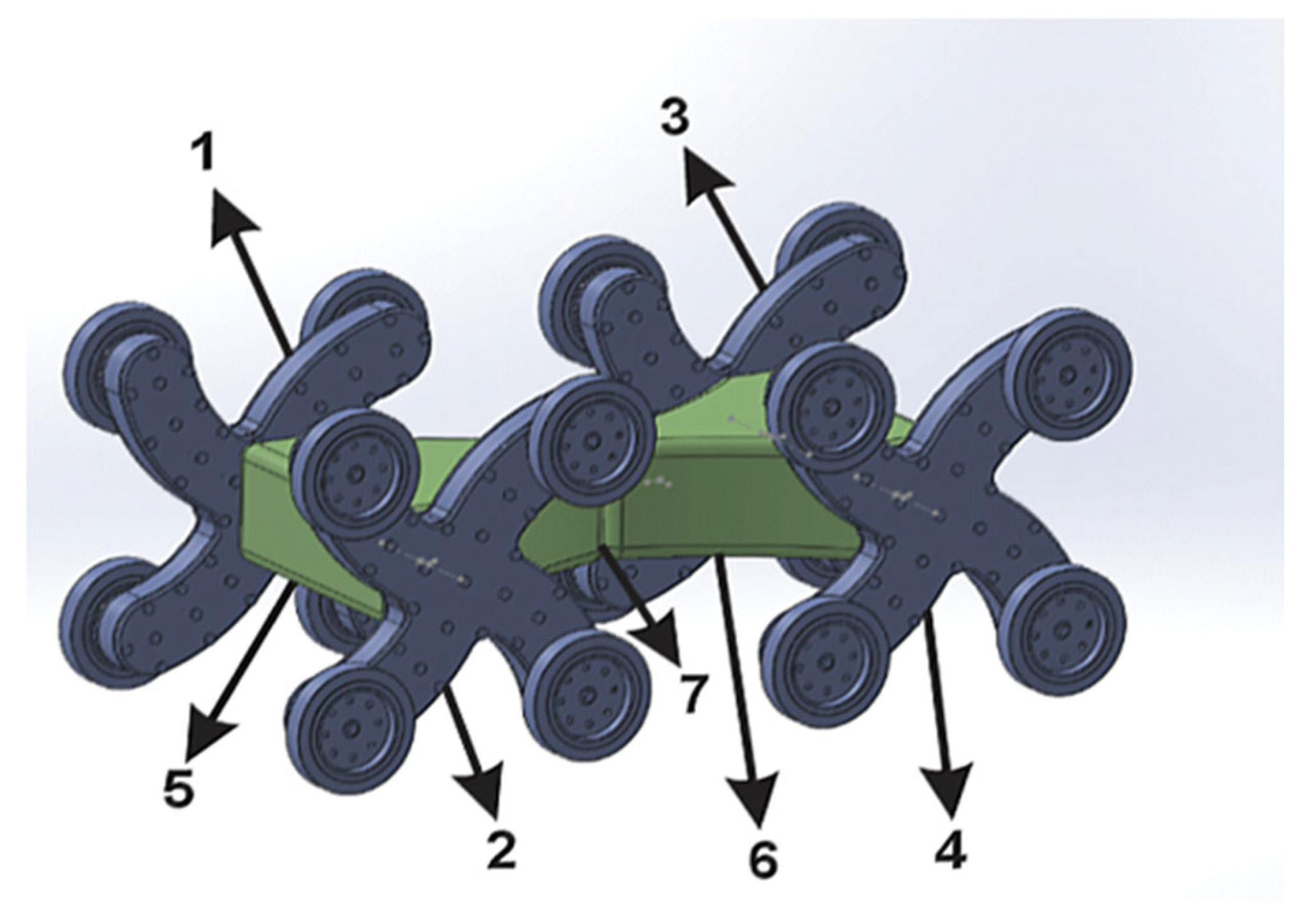
This model will be exported from the CAD system, and the first step in developing the simulation component involves exporting the meshes and the URDF file for the network’s mobile robots, ensuring compatibility with ROS2 and Gazebo simulation standards. In this context, the authors have designed a custom mobile robot model specifically tailored for deployment in emergency scenarios, employing a hybrid leg–wheel locomotion system that aims to improve mobility and adaptability across unstructured terrains, as illustrated in
Figure 4. The development of this model was grounded in an extensive review of the specialized literature concerning advanced locomotion mechanisms for mobile robots operating in emergency response missions.
The export process involves several steps that establish the connection between the CAD environment and the information management framework in ROS, specifically the Unified Robot Description Format (URDF). Exporting the URDF model using the URDF Exporter plugin from SolidWorks 2024 provides a raw representation of the robot structure. Consequently, this file must be refined and optimized through the use of Xacro syntax.
Section 2 details the methodology for exporting and optimizing the data in ROS-compatible format [
30].
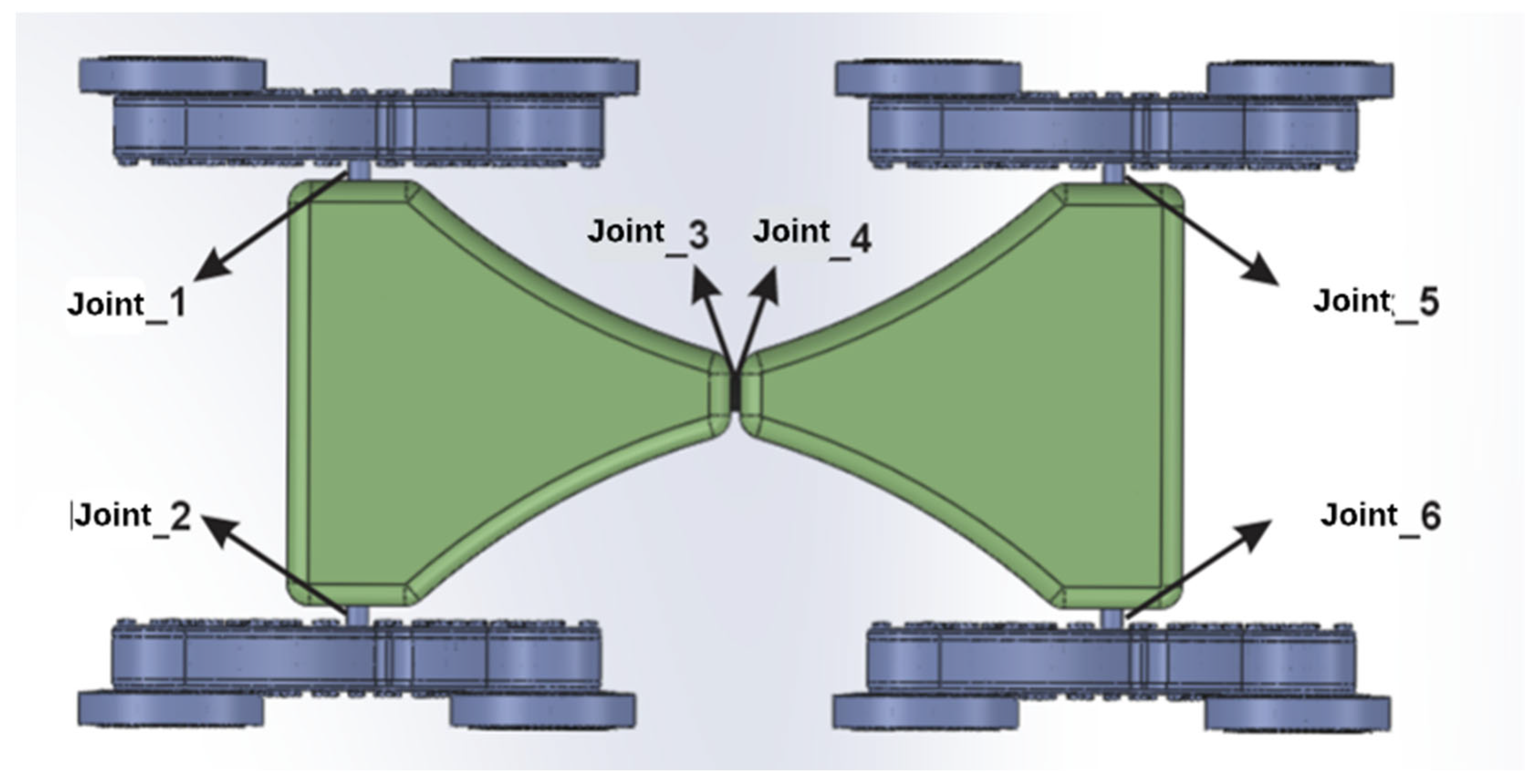
The export process requires the definition of the robot’s subassemblies (links) and the connections (joints) between them, followed by the specification of the kinematic coupling types. For the proposed mobile robot, all couplings between geometric elements are fifth-class rotational joints.
The export process involves defining the mobile robot’s subassemblies (links) and the joints connecting them, followed by the specification of the kinematic coupling types. For the proposed mobile robot, all couplings between geometric elements are classified as fifth-class rotational joints.
To simplify the initial simulation of the mobile robot, seven standalone subassemblies were defined, as presented in
Table 1.
A visual representation of the links listed in
Table 1 is provided in
Figure 5.
The next step involves the actual export of the model and the creation of configuration files for the ROS2 operating system. These files implicitly include the XML-based URDF file of the mobile robot.
The URDF Export plugin uses the coordinate systems assigned to each component, starting from the base element (base_link), which was manually defined within the CAD environment.
Model properties can be modified either directly within the plugin or subsequently, after the XML file has been generated.
Exporting the meshes in STL format for use in the simulation requires preprocessing and proper alignment relative to their respective 3D coordinate systems.
Figure 4 illustrates the geometry of all components of the mobile robot.
Figure 6 depicts the chassis, specifically designed to facilitate the integration of the locomotion modules, and illustrates the leg–wheel locomotion unit, which comprises four curved, articulated leg structures that enable hybrid mobility. Additionally, a passive central coupling element is incorporated to connect the front and rear segments of the chassis, allowing for structural flexibility and modular integration.
Based on these components, the URDF file and the mobile robot’s mesh model can be abstracted and integrated into the ROS2 and Gazebo simulation environment. The following section focuses on the configuration of the simulation environment.
3. Architecture and Deployment of the Simulation Subcomponent
To facilitate the installation and configuration of the ROS2 operating system alongside the Gazebo simulation environment, the virtualization capabilities of Hyper-V—Microsoft’s native hypervisor integrated within Windows—were employed to provision an isolated and controlled execution context. A dedicated virtual machine was instantiated to host Ubuntu 22.04 LTS, selected for its compatibility and long-term support status within the ROS2 ecosystem.
The virtualized environment was allocated 8 GB of dynamically managed memory, bounded by a minimum of 6.29 GB and a maximum of 12.92 GB, thereby ensuring adaptive memory utilization based on computational demand. Furthermore, the system was provisioned with four logical processing cores, all residing on a single Non-Uniform Memory Access (NUMA) node, which promotes optimal processor affinity and scheduling. The virtual machine architecture adheres to the Generation 2 specification, enabling support for UEFI boot and advanced features such as secure boot (disabled for Linux compatibility) and integration services including dynamic memory handling and guest communication interfaces [
31].
At the time of evaluation, the virtual machine had been continuously operational for over seven hours, exhibiting normal heartbeat and system status indicators, thus confirming the stability and readiness of the environment for intensive robotic simulation workloads. In order to dynamically simulate the mobile robot, beyond the initial configuration, additional functionalities are required to link the URDF file publication to the /robot_description topic and to the Gazebo environment. To achieve this, two ROS2 packages were created, each responsible for one of the two core functionalities:
my_robot_description—for publishing the URDF file to the corresponding topic and launching it within the Gazebo environment;
my_robot_bringup—for spawning the mobile robot and instantiating the scanning node
- (a)
my_robot_description package
This package is structured around multiple configuration files that read, install, and launch the functionalities required to transmit URDF data to the Gazebo environment
The /meshes folder contains the subassemblies exported from SolidWorks, which serve as link elements within the Gazebo environment.
The /urdf folder stores the robot’s structural information in an optimized format. The remaining files are responsible for launching and configuring RViz, URDF, and mesh resources for data transmission to the /robot_state_publisher topic.
- (b)
my_robot_bringup package
This package is responsible for spawning the mobile robot within the Gazebo environment by interfacing ROS2 with the ros_gazebo plugin. The first step involves launching Gazebo in basic factory mode, followed by linking the /robot_state_publisher topic to the simulator. Gazebo acts as a subscriber to this topic and receives continuous updates regarding the robot’s position. Also, the map scanning node is called in order to teach the robot the actual environment using SLAM.
These packages will transmit and receive information via ROS nodes in order to enable dynamic simulation within the Gazebo environment. Subsequently, the URDF file—extracted from the SolidWorks CAD environment—will be processed using Xacro syntax, and additional functionalities will be configured to enable robot motion.
Dynamic simulation in Gazebo requires modifying the URDF file using Xacro syntax and incorporating information related to mass and inertia by defining the inertia tensor, along with collision-related properties. Regarding the joints of the mobile structure, these are defined using the standard Xacro block, where their position, orientation, and type are specified. Some joints also include abstracted mechanical constraints.
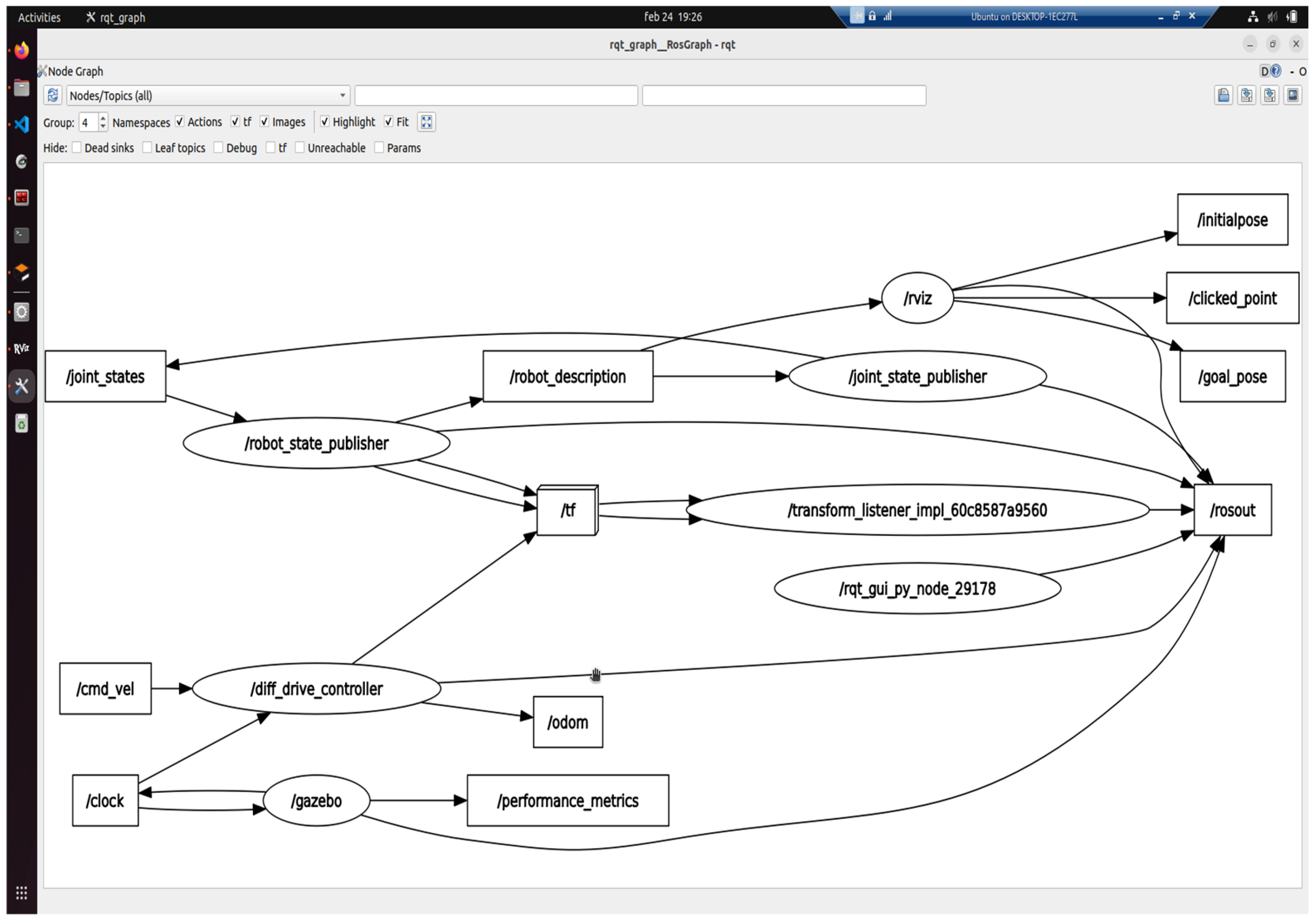
This information is retrieved from the Xacro file by the /my_robot_description package and published to the /robot_description topic, from which it is subsequently propagated to the /rosout topic. This allows the data to reach the /gazebo node, where the /my_robot_bringup package uses the spawn function to instantiate the mobile robot within the simulation environment. This informational flow is illustrated in
Figure 7.
Additionally,
Figure 7 also defines the control of the mobile robot’s DC motors using the /cmd_vel and /odom topics. Within these two topics, the /diff_drive_controller node publishes control and feedback data, and it is defined in the Xacro file.
A distinct controller will be configured for each pair of wheels, resulting in a total of four differential drive controllers, one per locomotion module, distributed symmetrically across the robot’s base.
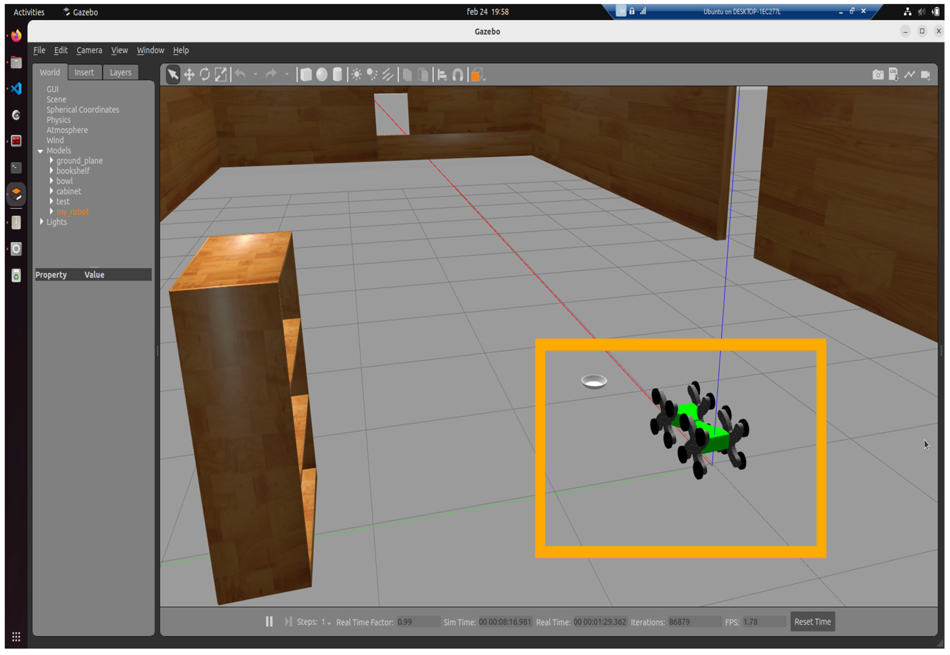
Once these nodes and topics have been properly set up, the mobile robot was spawned in the Gazebo environment by executing a launch file that instantiates all associated functionalities. The resulting simulation of the mobile robot can be observed in
Figure 8.
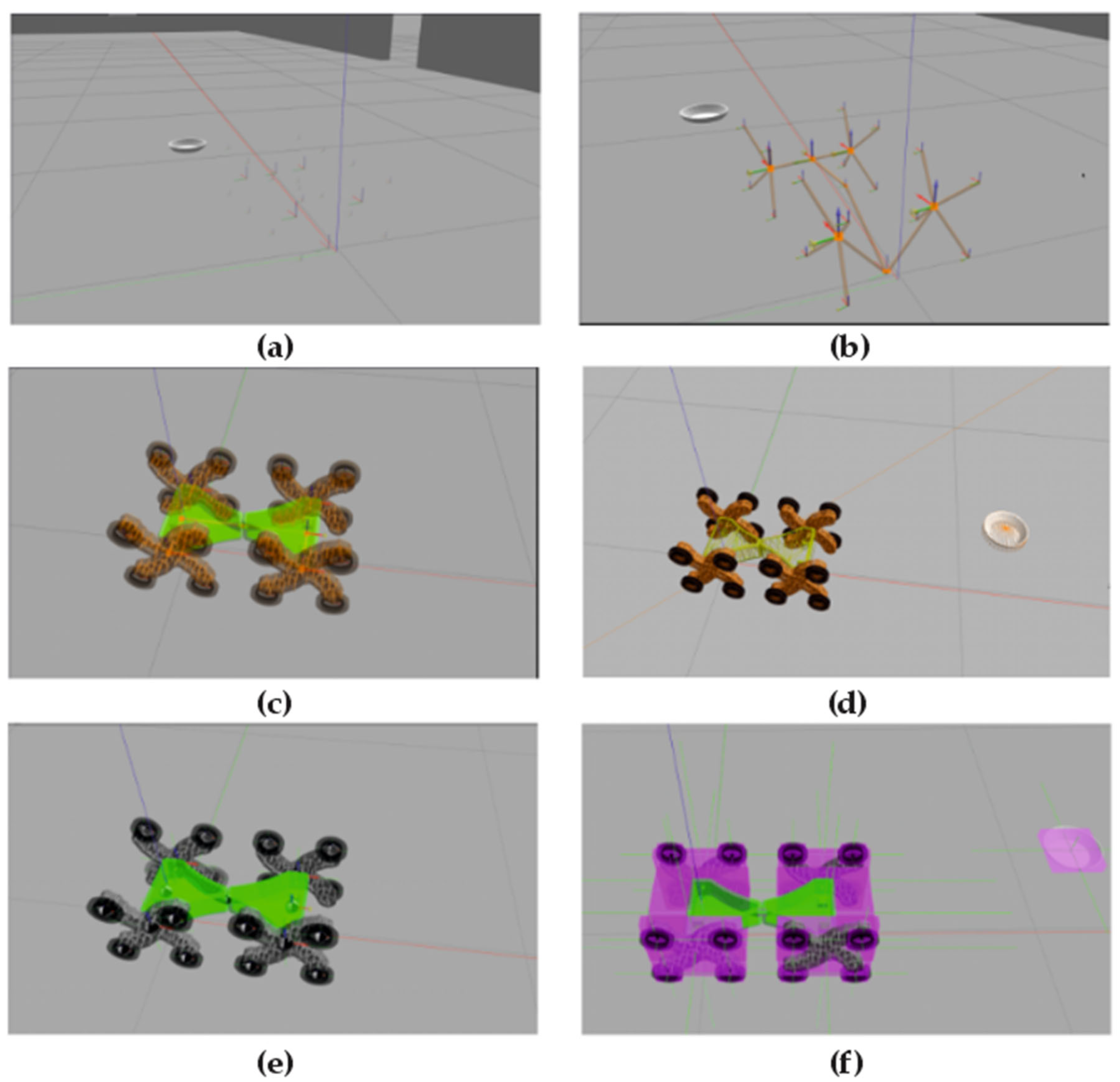
The selected environment serves as a test model for evaluating locomotion on flat surfaces. Gazebo provides various functionalities for visualizing coordinate frames of structural links, visual geometry, collision boundaries, inertial properties, and mass distribution. These aspects are illustrated in
Figure 9a–f, extracted from the Xacro file.
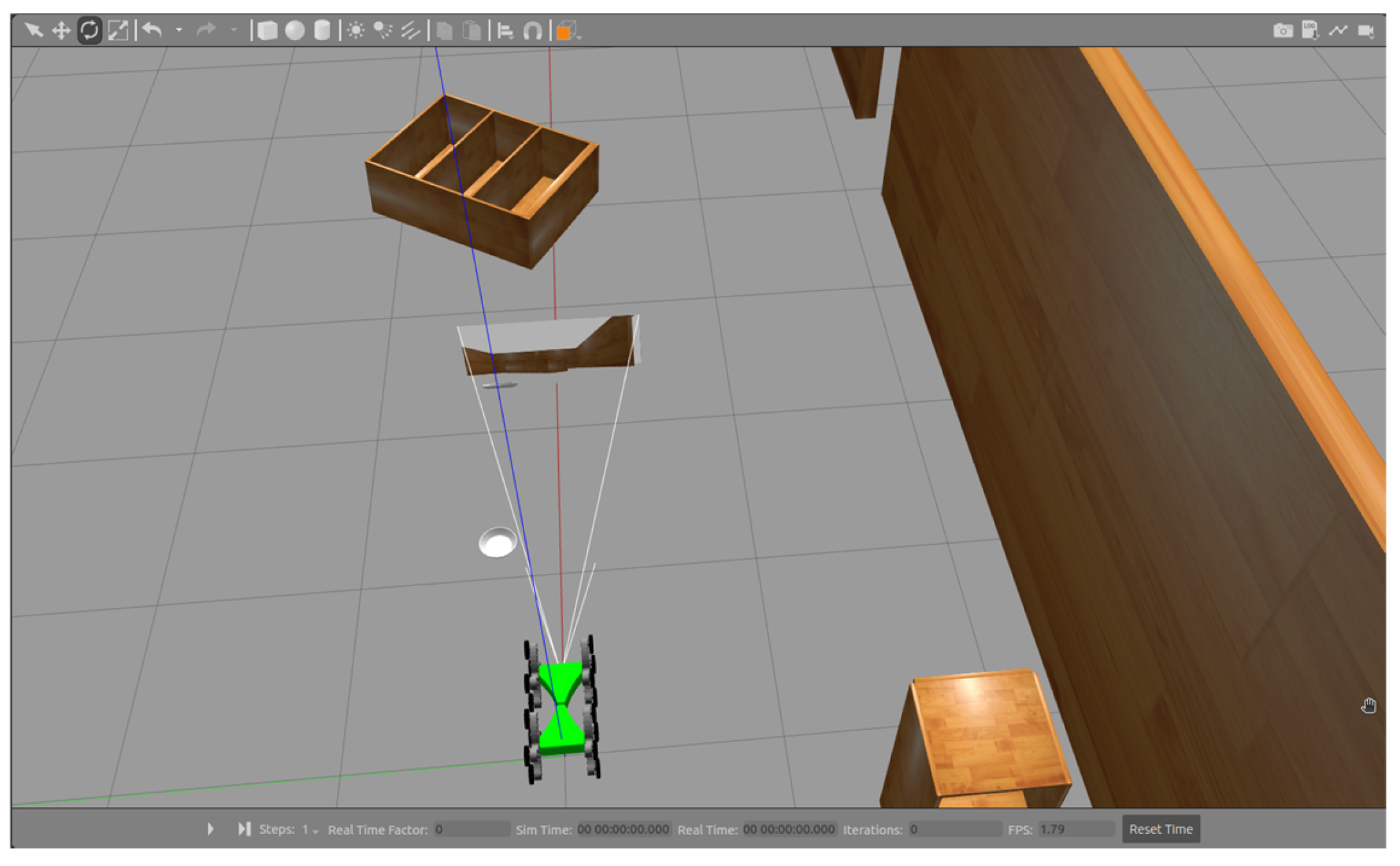
For the testing phase, a virtual sensor was also added to the Xacro configuration, an RGB camera mounted at the front of the mobile robot, as shown in
Figure 10.
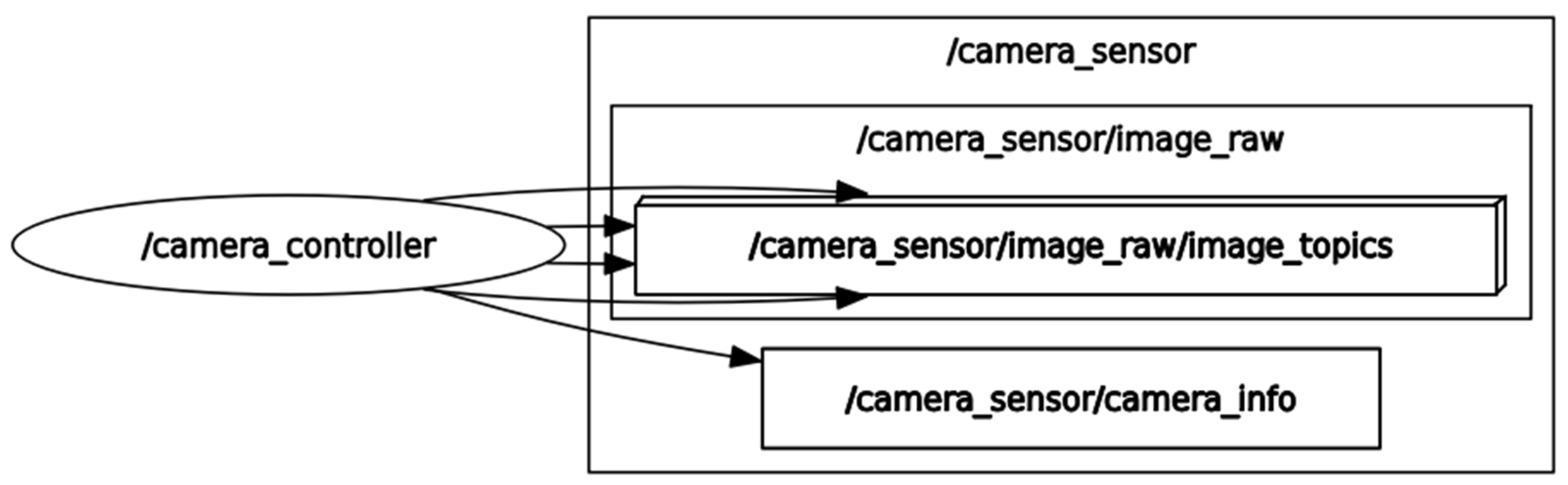
This component will retrieve audio/video data from the simulation environment and publish it to the /camera_sensor topic, as shown in
Figure 11.
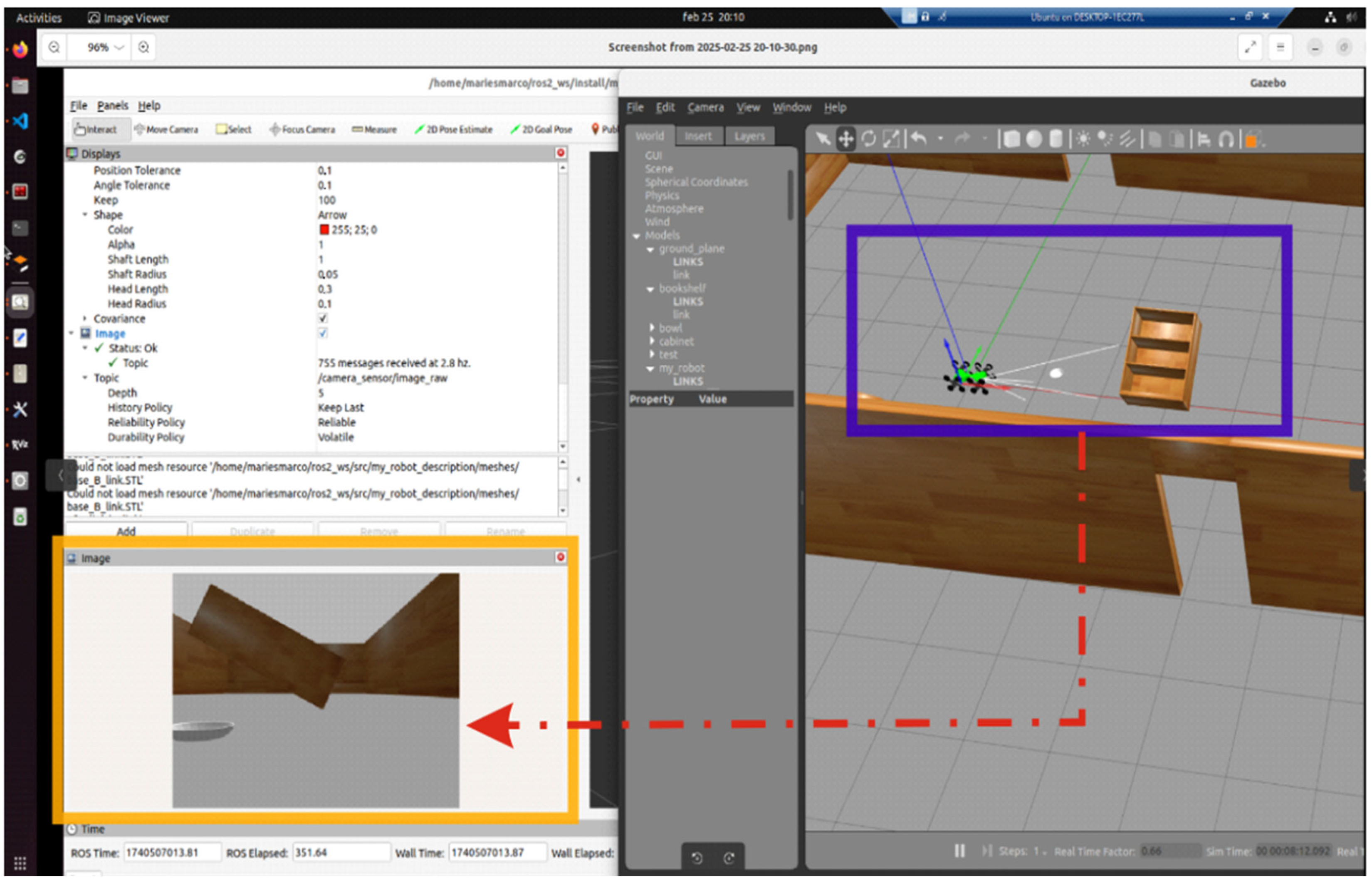
This plugin utilized the /libgazebo_ros_camera.so library. The images captured by the AV camera can be transmitted through the topic it publishes to and redirected to the robotic network server via the WSS protocol for display within the WebPlatform [
32]. The testing phase for the AV camera functionality involved using the images published to the /camera_sensor topic, which were then subscribed to and visualized in RViz2 (the static simulation environment in ROS2), as shown in
Figure 12.
In conclusion, these functionalities can be further extended through the development of ROS–Gazebo microservices [
20,
21] and the creation of a structured information flow within the system. The following section presents the dynamic Gazebo simulation of a mobile robot within the test environment.
4. Dynamic Simulation of One Mobile Robot Using Flat Surfaces
Dynamic simulation necessitates the use of a virtual environment, commonly referred to as a world. For the testing phase, a simulation scenario was selected that includes a flat surface and several structural elements resembling those typically encountered in an indoor setting. The experimental setup comprises a workspace enclosed by four walls, covering an area of 5 × 20 m2, specifically designed for the virtual evaluation of the robotic prototype. The mobile robot has compact overall dimensions of approximately 0.03 m in length, 0.02 m in width, and 0.015 m in height, which facilitates its deployment in narrow and cluttered environments during search and rescue operations. In the current study, the focus was limited to planar surfaces. Locomotion was achieved by applying linear velocity commands to the /cmd_vel topic. It is important to highlight, however, that the prototype is engineered to overcome obstacles and ascend stairs with a height not exceeding half of the robot’s total height. A dedicated simulation campaign is currently under development to assess the robot’s climbing performance under various conditions, including the traversal of obstacles and step-like structures. The ROS2 and Gazebo configuration described in the previous section was used. This configuration is launched via a launch file named /display.launch.xml, developed within the /my_robot_description package. Its purpose is to instantiate all communication and simulation components of the proposed architecture.
As a result, the mobile robot model was successfully transmitted and instantiated in the Gazebo simulation environment without errors, based on the system log output.
The system is controlled entirely through the Ubuntu terminal, using a Bash shell to interact with the virtual kernel elements. The log summary confirms the successful parsing of the Xacro file elements, their publication within the Gazebo environment, and the acceptance of the virtual control configuration for the DC motors.
During the robot launch sequence, four distinct differential drive controllers (diff_drive_controller_1 through diff_drive_controller_4) were successfully initialized, each managing a pair of wheel joints symmetrically assigned across the robot’s base. These controllers correctly subscribed to the /cmd_vel topic for velocity commands, published odometry to /odom, and actively broadcast transform frames between the base_footprint and their respective wheel joints. Wheel parameters, including a uniform diameter of 0.0886 m and a pairwise separation of 0.32204 m, were consistently reported, indicating a well-synchronized multi-controller architecture for distributed wheel actuation in the simulated locomotion model. Each controller relies on the gazebo_ros_diff_drive plugin, which includes an internal PID velocity control loop automatically integrated within the plugin’s library (libgazebo_ros_diff_drive.so). This ensures that each wheel pair tracks its target speed smoothly without requiring external tuning unless specified.
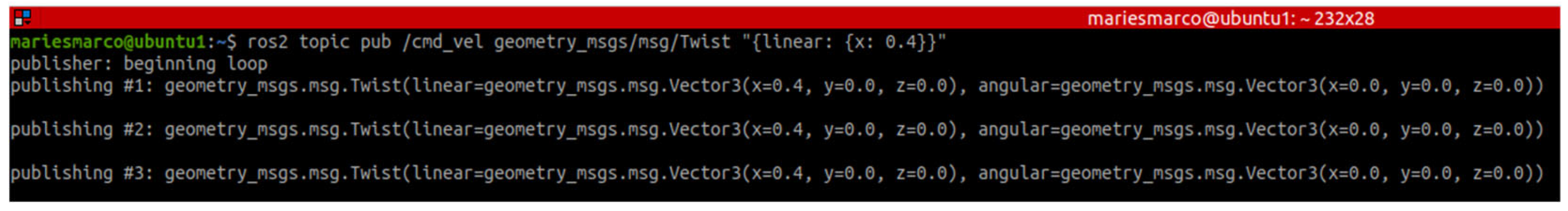
To print the velocities of the DC motors, Vectors 3 and 5 must be configured—corresponding to the linear and angular vectors. For the testing phase, data were published to the /odom topic using the /geometry_msgs/msg/Twist interface. In ROS2, this vector is generically referred to as Twist.
The linear velocity will be published in the Vector 3 subvector of the Twist vector, with a value of 0.4 m/s, as shown in
Figure 13.
Thus, the mobile robot will move within the workspace at the velocity published to the /cmd_vel topic by transmitting the Twist vector using the /geometry_msgs/msg/Twist interface.
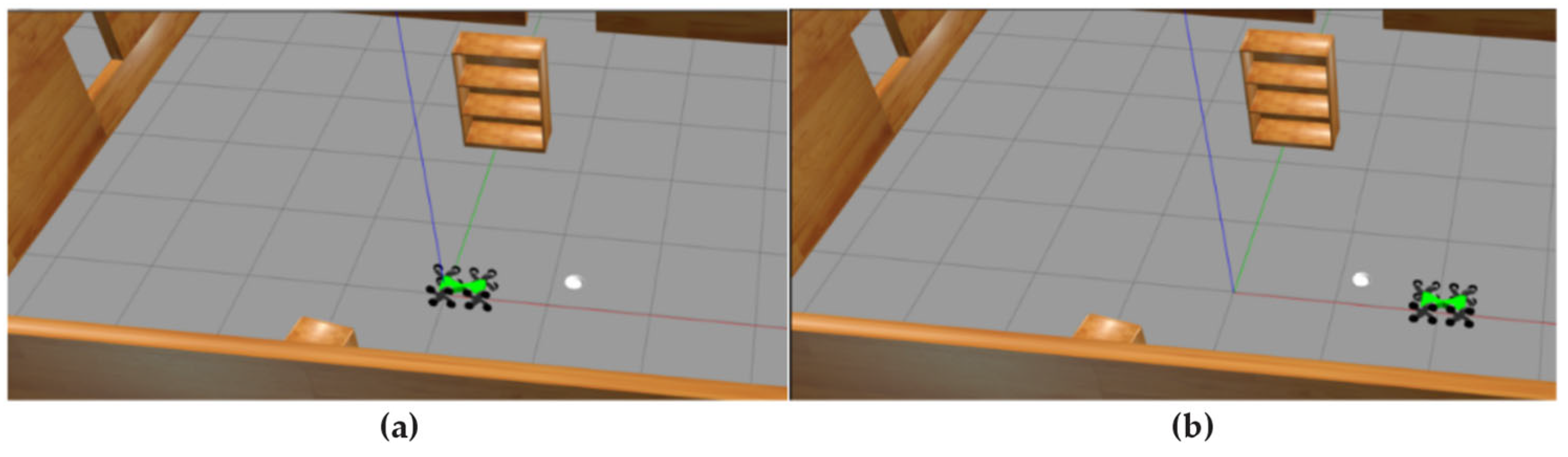
Figure 14a,b show two positions of the mobile robot following its linear movement along the x-axis.
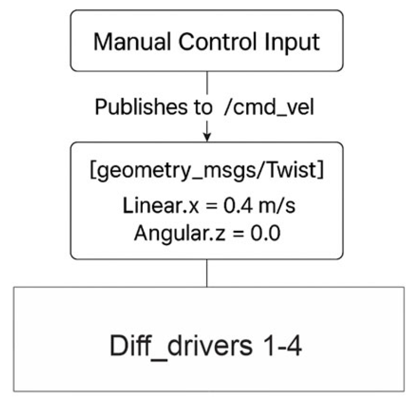
A logical scheme is shown in
Figure 15, which reflects the current method of control development and is based on a manual input of the linear velocity.
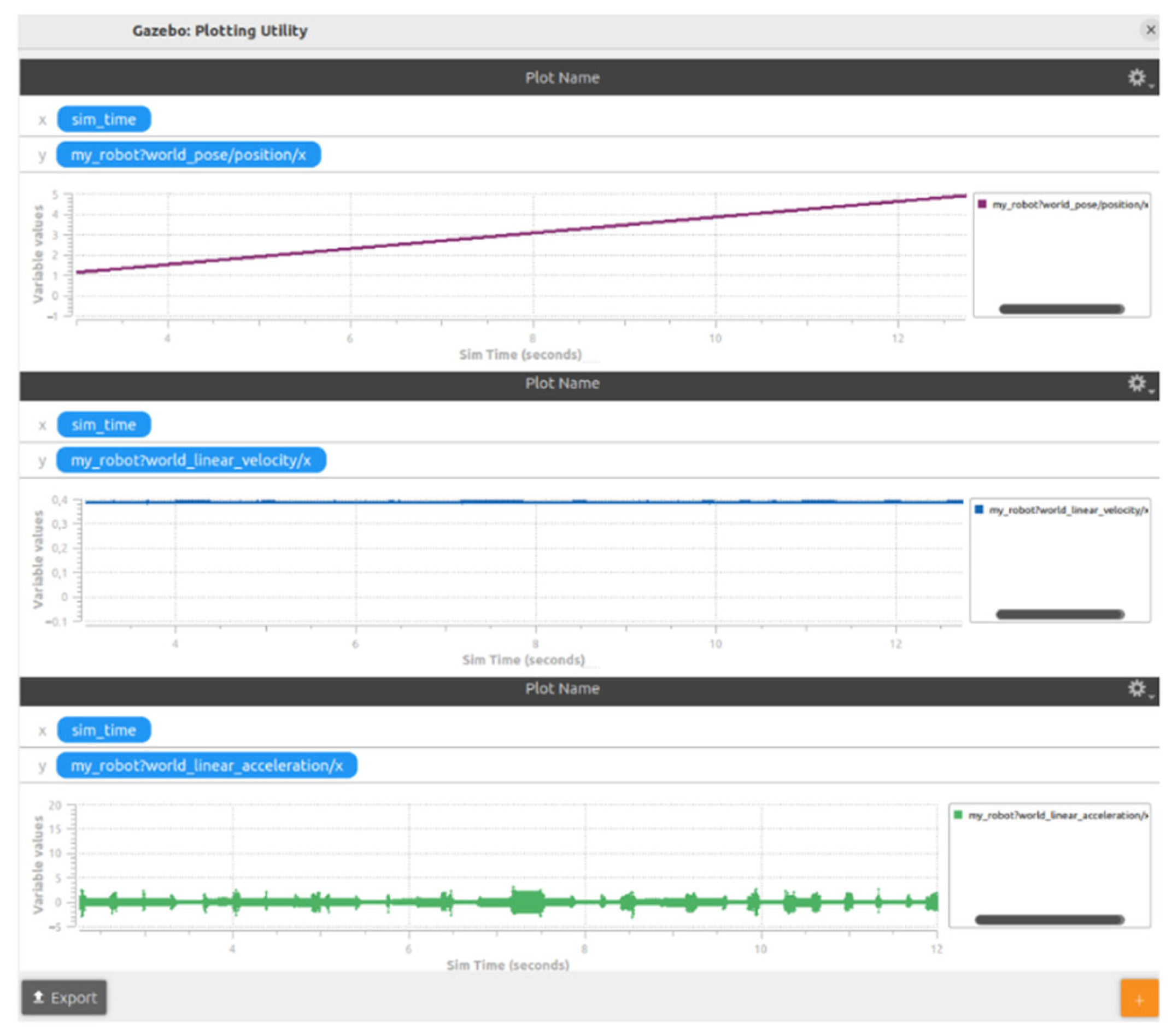
Additionally, a graph was extracted showing the position, linear velocity, and linear acceleration of the mobile robot along the x-axis, as presented in
Figure 16. The simulation was conducted over a duration of 13 s.
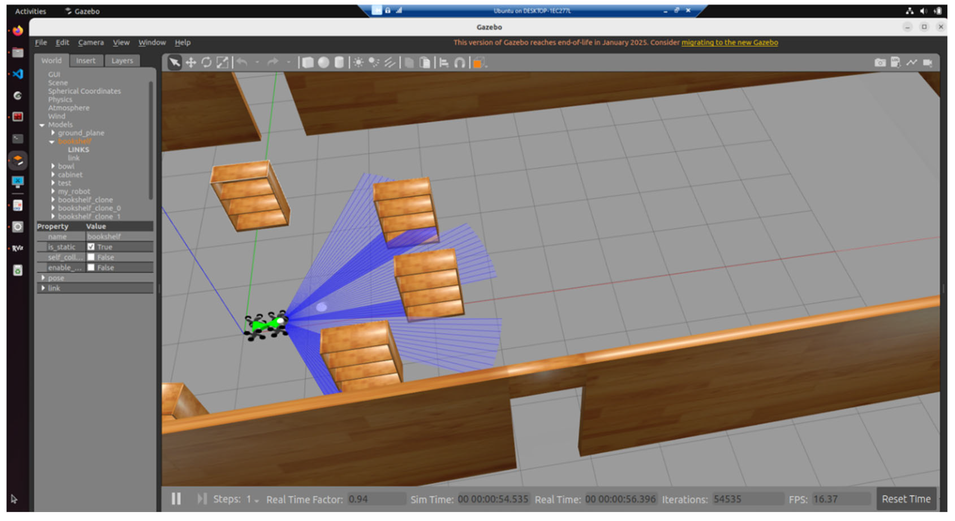
These values were extracted by the /odom topic interrogation. This was an initial test, which confirms the actual functionalities of the motion metrics, including the linear velocity. Now, a 2D LiDAR sensor is simulated for scanning the actual stage. This sensor, with a scanning field of ±60° and an angular resolution of 0.5°, has been integrated into the system. The sensor operates at an update rate of 10 Hz and provides a maximum range of approximately 3.5 m, allowing the robot to detect and react to nearby obstacles within its frontal sensing arc, shown in
Figure 17.
In this study, we employ the Cartographer SLAM framework to perform real-time mapping and localization using 2D LiDAR data within a simulated environment. Cartographer follows a graph-based SLAM paradigm, wherein a pose graph is incrementally constructed by matching incoming laser scans to localized submaps. These pose constraints are globally optimized using nonlinear least-squares methods (via Ceres Solver), yielding a globally consistent map and trajectory estimate. Compared to probabilistic approaches such as FastSLAM or GMapping, which rely on particle filters and resampling techniques, Cartographer leverages deterministic scan matching, loop closure detection, and pose graph optimization, ensuring accurate and efficient map construction without the computational overhead of particle filtering. The method aligns well with the operational needs of emergency robotics, where rapid and robust environmental understanding is crucial.
This configuration enables the robot to autonomously stop when an obstacle is detected directly ahead. An obstacle avoidance algorithm is currently under development, aiming to implement a progressive turning behavior upon obstacle detection, thereby enhancing the system’s autonomy in dynamic environments.
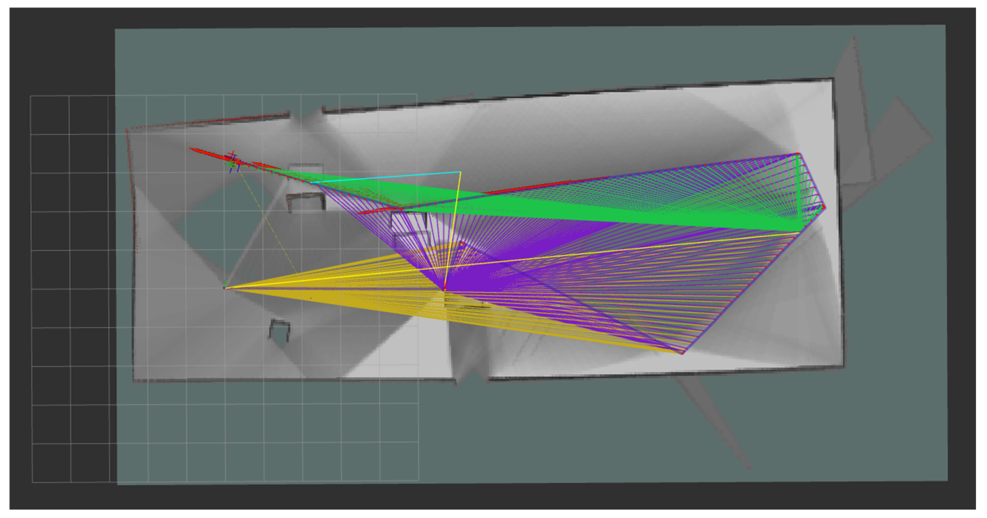
The robot was tested in a virtual environment over a 10 min randomized motion sequence, using linear velocity commands of 0.4 m/s published to the /cmd_vel topic, as described in
Figure 18. During this exploration, the LiDAR sensor continuously scanned the environment, contributing to a qualitative assessment of spatial awareness and real-time perception. The SLAM process was performed using the Cartographer ROS2 framework, which operated on the standard topics: /scan (2D LiDAR), /odom (odometry), /tf, and /tf_static for frame transformations. Sensor data were sampled at 10 Hz, and the occupancy grid was generated with a resolution of 0.05 m per cell. The robot’s true position was obtained from the /gazebo/model_states topic and used as a reference for validating the overall mapping consistency within the simulated 5 × 20 m
2 environment. The colored trajectories denote shifts in the robot’s orientation, thereby reflecting the LiDAR sensor’s new field of detection.
The simulation-based mapping of the environment using a LiDAR sensor plays a critical role in preparing autonomous robotic systems for real-world emergency scenarios. By enabling the robot to construct an internal spatial representation through sensor-based perception, it becomes possible to simulate diverse hazardous conditions—such as cluttered environments, blocked passages, or dynamic obstacles—within a controlled virtual setting. This allows for safe, repeatable, and scalable testing of the robot’s behavior under stress, without risking physical damage or human safety. Furthermore, the generated occupancy maps serve as foundational data for training and refining adaptive control strategies, enabling the robot to make informed navigation decisions, optimize path planning, and improve its resilience when facing unexpected structural changes or obstructions during emergency response missions.
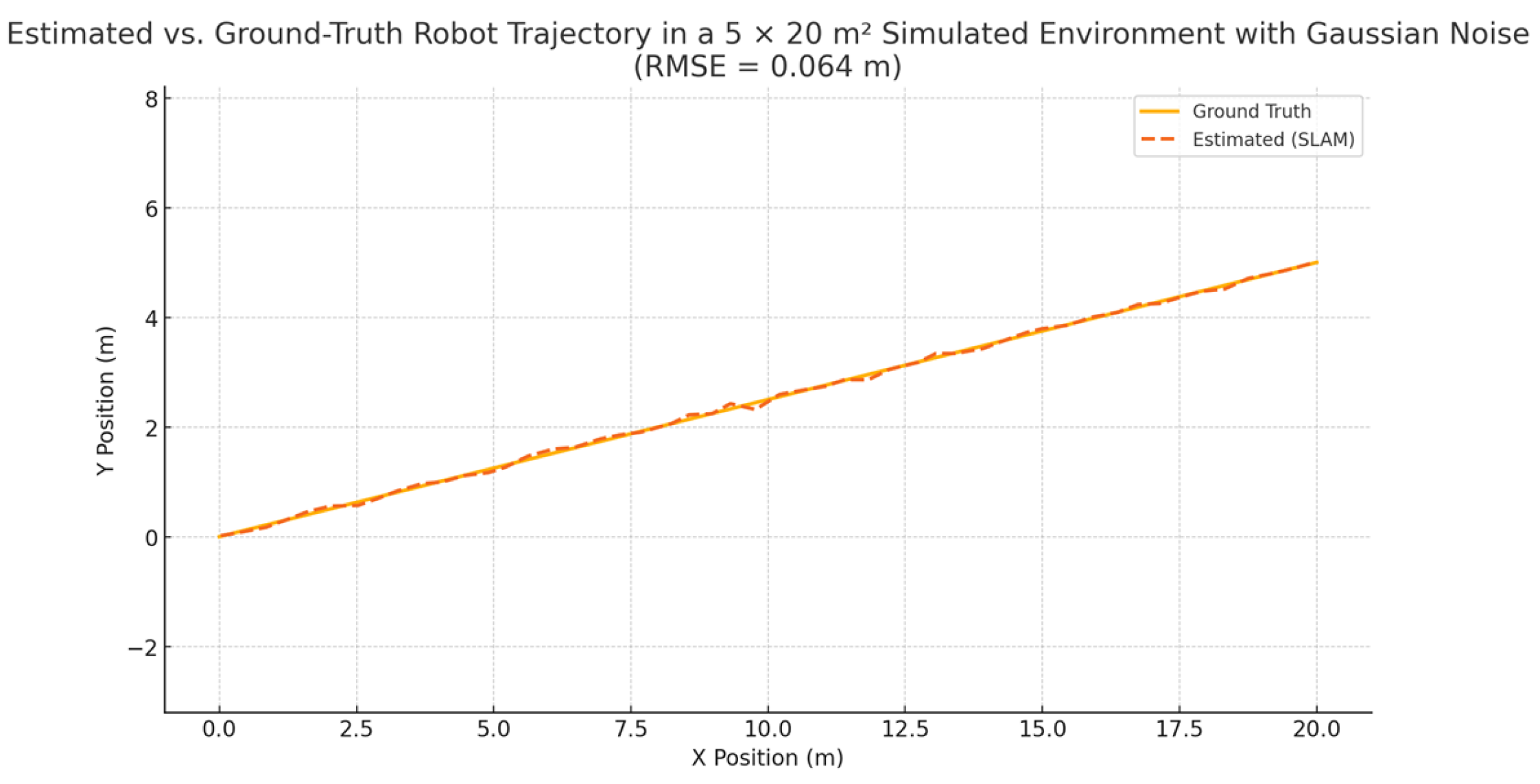
To simulate realistic sensor and localization noise, Gaussian perturbations with a standard deviation of 5 cm were added to the robot’s estimated trajectory. The resulting Root Mean Square Error (RMSE) between the estimated path and the ground-truth trajectory was 0.064 m, demonstrating high localization accuracy in the simulated environment, as shown in
Figure 19.
Section 5 introduces a method for interconnecting two mobile robots within the Gazebo simulation environment, enabling collaborative map exploration with the aim of increasing the overall success rate of environmental coverage.
5. Connecting Two Mobile Robots in the Gazebo Simulation Environment
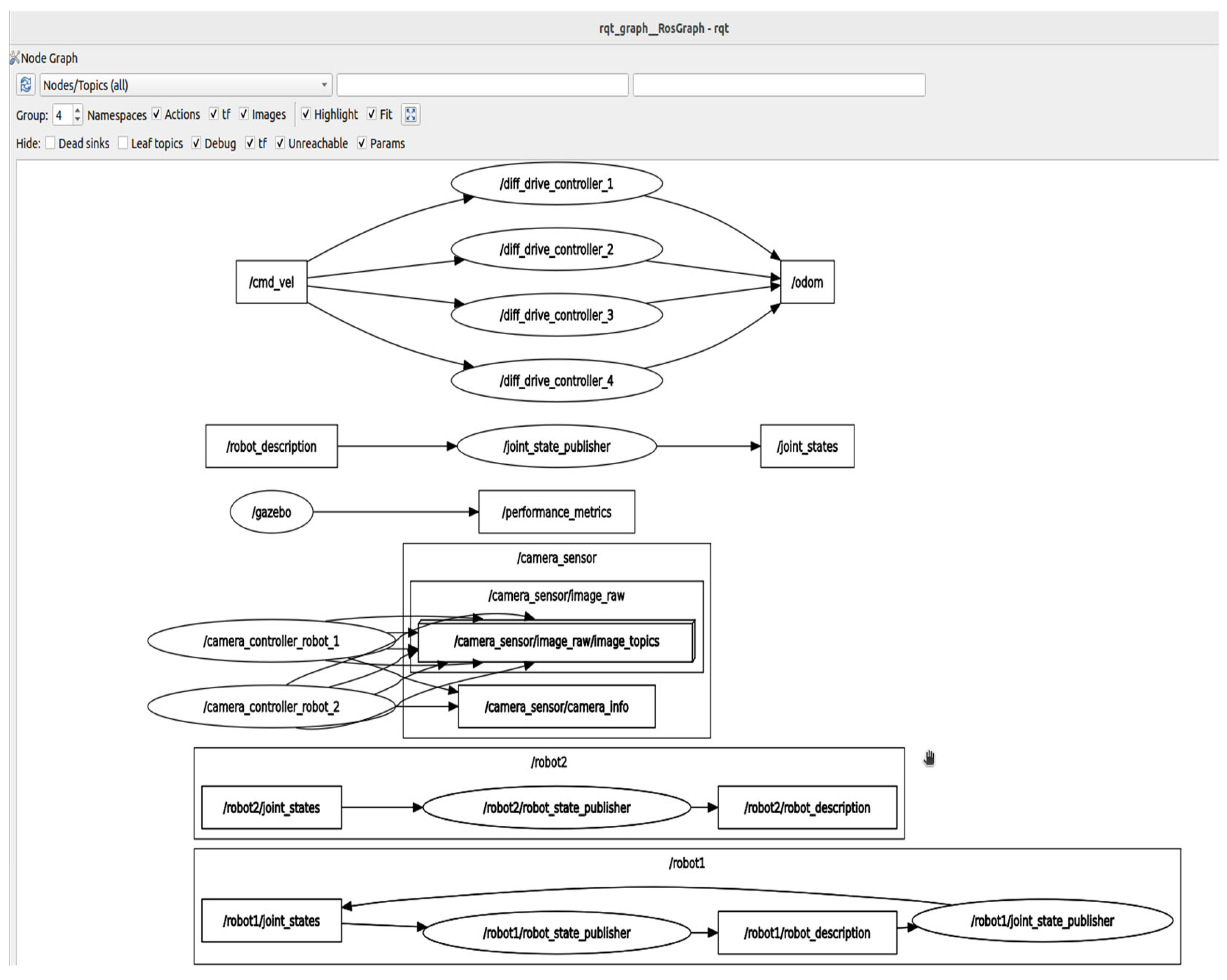
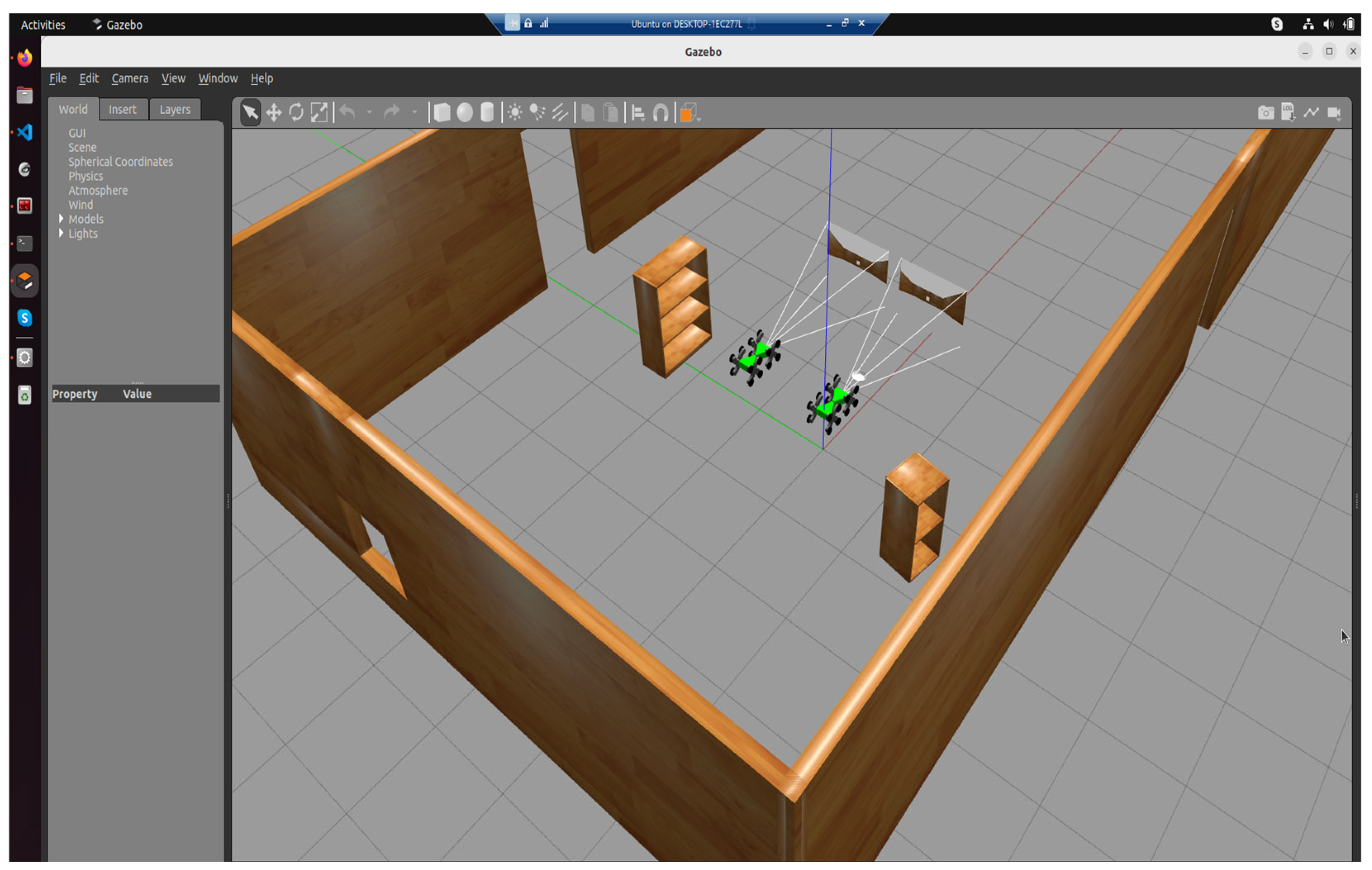
The Gazebo simulation environment allows for the spawning of multiple entities, in this case, mobile robots, by modifying the system configuration. Accordingly, the ROS packages and launch files were adapted to support the deployment of two identical mobile robots, with the communication architecture illustrated in
Figure 20. This configuration, visualized using rqt_graph, displays the ROS package nodes specific to each mobile robot instance, /robot1 and /robot2, which publish and receive information from both Gazebo topics and the AV camera topic.
Thus, after instantiating all necessary packages via two launch files, the mobile robots were successfully spawned in the Gazebo simulation environment, as shown in
Figure 21.
To enhance environmental coverage and assess the effectiveness of the mapping process, two mobile robots were employed to scan the environment simultaneously, each using its own onboard LiDAR sensor. The robots were manually controlled, and their trajectories were planned to ensure complementary coverage of the workspace. Through this cooperative exploration strategy, a complete occupancy map was successfully generated, with a 100% coverage rate achieved during a single scanning session. The experiment highlights the potential of multi-robot systems in improving mapping efficiency, even under manual control and in the absence of autonomous navigation algorithms. The distance between these two robots was 2 m.
The authors aim to extend these functionalities by testing various simulation environments, such as a dedicated search and rescue scenario. Due to the high computational load of the virtual machine, mainly caused by the simulation of realistic robot collisions, only two mobile robot entities were instantiated during the current phase.
The Future Work section proposes increasing the processing power of the virtual machine and introducing ROS2-orchestrated microservices to enable a fully networked operational model. This functionality will allow mobile robots to collaborate with one another and transmit data both within the ROS2 environment and toward the Minikube cluster.
6. Conclusions and Future Work
In conclusion, this work focused on the development of the simulation subcomponent of the robotic network through the implementation of ROS2 and Gazebo technologies. This subcomponent is part of a much more complex system that will be further developed using Kubernetes orchestration technologies.
Emergency scenario simulation is essential, as it enables foresight and anticipation of the complex events typically encountered in such situations. For this reason, it is of significant interest to leverage simulation as much as possible, both for training the robotic system and for preparing the human personnel involved. This approach helps reduce the risk of injury to personnel assisting in field missions. Moreover, simulation environments allow for the generation of accurate maps using SLAM techniques, which serve as a foundational layer for navigation, mission planning, and environment-aware decision-making in real deployments. Based on this perspective, the development of such networked robotic systems, equipped with integrated simulation capabilities, is both justified and of great relevance. The scientific literature reflects this trend and presents various configurations that integrate and simulate mobile robots within distributed networks. These configurations require continuous research and optimization, as emergency situations are highly dynamic and subject to constant change.
The proposed activities for the further development of the simulation environment focus on two key stages related to the integration of this component into networked architecture.
The first stage involves expanding the virtual machine by allocating additional resources, enabling the integration of multiple mobile robots within the simulation environment. Additionally, the authors aim to develop ROS2 microservices to manage the data exchanged via nodes and topics in an automated manner, ensuring its transmission to the Minikube cluster, specifically to the server pod of the robotic network. For this information to be processed by the network server, a secure and encrypted connection is required. To this end, a ROS Bridge will be used to connect the Hyper-V virtual machine to the network server. The authors propose a WSS model secured with TLS encryption and the use of HTTPS requests for data exchange. Furthermore, an alternative communication node based on the gRPC protocol is proposed, intended for mobile robots with higher processing capabilities that can support such libraries.
The second stage of development involves designing emergency scenarios using specialized simulation environments and proposing communication strategies. Based on previously acquired maps through SLAM techniques, this stage will focus on the development of Nav2-based obstacle avoidance algorithms and the training of mobile robots in various scenarios involving obstacle circumvention or traversal. Furthermore, this phase will incorporate noise analysis to evaluate the robustness and reliability of navigation strategies under sensor uncertainty and environmental disturbances.
An initial network operation model is presented in
Table 2, simulating the phases of a search and rescue mission involving three mobile robots, two ground-based and one aerial.
Building upon this operational paradigm, a comprehensive suite of microservices will be systematically engineered to encapsulate the core functional components essential to search and rescue missions in emergency contexts. These microservices will be designed to operate in a distributed and modular manner, each responsible for specific capabilities such as sensor data acquisition, environment perception, path planning, obstacle avoidance, inter-robot communication, and decision-making under uncertainty.


