1. Introduction
With rapid urbanization and advances in construction technology, the trend toward larger buildings has accelerated, increasing risks to human life during fires owing to more complex evacuation routes. In the 2017 Jecheon Sports Center fire, for example, a combination of factors—including blocked emergency exits, rapid smoke spread, and delayed evacuation—resulted in significant casualties. The incident revealed structural vulnerabilities, particularly the inadequacy of fire compartmentalization and evacuation safety [
1]. Such incidents highlight the critical importance of establishing effective fire compartments and properly implementing their key components, such as firestop systems, to prevent fire from spreading and minimize risks to life and property.
Fire compartments rely on fire-resistant structural elements and components, such as fire doors and shutters at openings. Equally crucial are firestop systems, which fill gaps around service penetrations and play a vital role in maintaining compartment integrity [
2,
3,
4,
5]. Modern buildings contain various utilities, such as plumbing, electrical, and telecommunication systems that penetrate walls and floors, creating potential pathways for fire to spread. To mitigate this risk, various firestop systems are installed at these penetrations [
6,
7].
In South Korea, a firestop system approval regime was introduced in 2022 to prevent fire spreading through compartment penetrations. Firestop systems comprise diverse materials and installation methods, such as intumescent wraps and sealing compounds, and research on their performance is actively ongoing [
8,
9,
10,
11,
12]. However, most existing studies focus on material properties, component geometries, or installation techniques. There remains a lack of quantitative experimental data directly applicable to improving the approval system, such as the relationship between firestop material volume and penetration size variations [
13,
14,
15,
16].
A critical issue in current systems is that even when the size of openings or penetrants is reduced, the same quantity of firestop material specified in prior approvals must still be applied. This often results in excessive application that does not reflect on-site conditions and creates inefficiencies, as separate approvals are required for each configuration. Meanwhile, several advanced countries have adopted flexible, performance-based certification frameworks—such as those based on ASTM E814 [
17] and UL 1479 [
18]—which allow for variable firestop specifications depending on penetration size and type. The uniform criteria in Korea, even under varying field conditions, incur unnecessary costs and promote inefficient construction practices [
19]. Therefore, there is a pressing need to transition toward a performance-based, evidence-supported standard that reflects practical on-site conditions.
In this study, the fire-resistance performance of firestop systems in metallic and nonmetallic pipe penetrations is experimentally investigated by adjusting firestop material volume in accordance with changes in opening size and penetrant diameter. By comparing conventional conditions with situations in which the firestop material volume was incrementally reduced based on cross-sectional area, the potential for more flexible firestop design is explored and performance differences identified by penetration type. The findings aim to provide technical and empirical data to support improvements to Korea’s firestop approval system.
2. Experimental Plan and Method
2.1. Experimental Plan
This study was conducted to obtain empirical baseline data to support the development of performance-based application standards for firestop system approval in Korea. In particular, it focuses on addressing a limitation of the current approval system, which requires a fixed volume of firestop material regardless of any reduction in opening or penetrant size. The aim is to quantitatively analyze how fire-resistance performance changes when the volume of firestop material is adjusted according to the cross-sectional areas of both the opening and the penetrant.
The experiment was conducted separately for metallic and nonmetallic pipes, based on their thermal characteristics and structural continuity. Each condition was defined by combinations of opening and penetrant areas, calculated using the actual measured outer diameters. Although nominal sizes were categorized such as 50–100 mm, and 75–125 mm, all analysis and comparisons were based on actual cross-sectional area measurements derived from real dimensions.
Metallic pipes maintain structural integrity even at high temperatures and serve as direct paths for heat transfer. In contrast, nonmetallic pipes tend to soften or disintegrate beyond a certain temperature depending on the material, losing their structural function. Therefore, it was anticipated that the two pipe types would exhibit different fire-resistance behavior under identical firestop conditions. To verify this, five different opening–penetrant combinations were established for each pipe type; the detailed configurations are presented in
Table 1 and
Table 2.
The firestop material was applied uniformly under all conditions with a fixed thickness of 7.8 mm and a width of 40 mm. The applied area was incrementally adjusted by varying the length of material along the opening’s perimeter. For the largest-opening condition, firestop material covered approximately 95% of the perimeter; this coverage was progressively reduced to 94%, 93%, 92%, and 91% depending on the experimental configuration. This approach enabled a comparative analysis of how reductions in firestop-material volume affect fire-resistance performance. This method was selected to simplify experimental variables, while also reflecting common field practices where shorter application lengths are typically used for smaller openings.
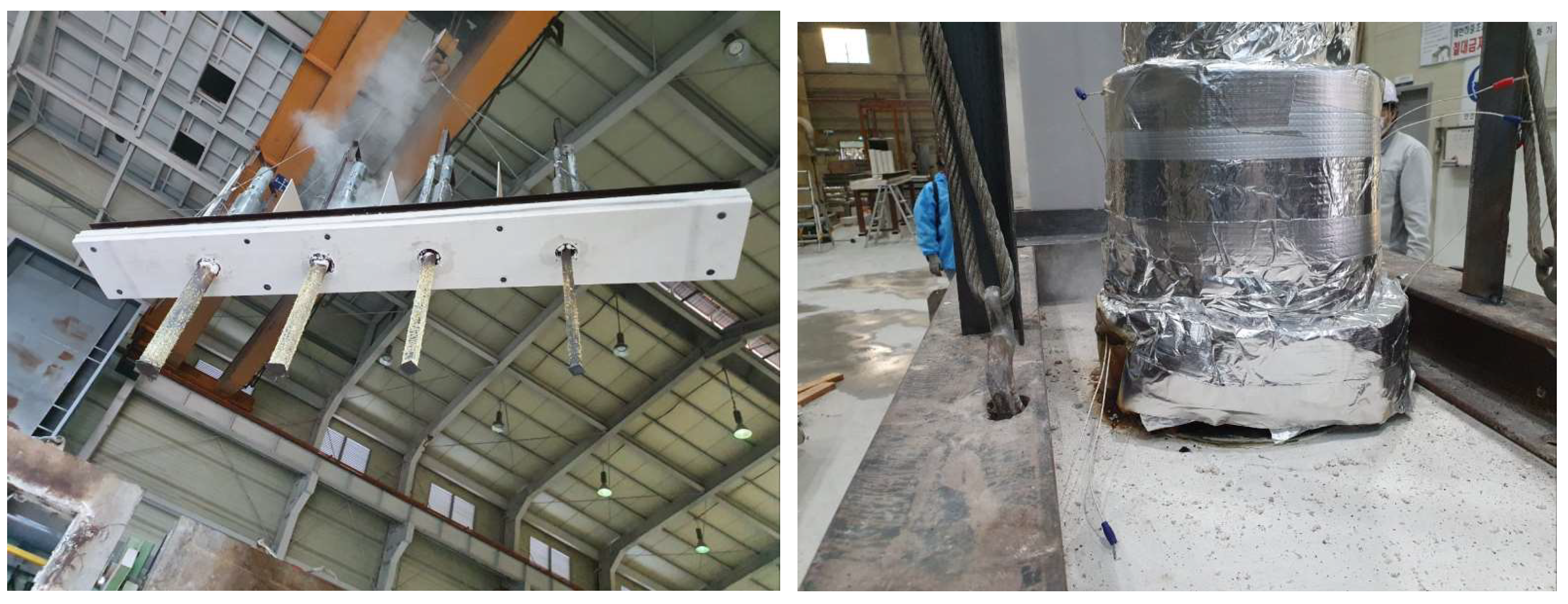
Figure 1 shows the physical arrangement of the specimens, including the penetration opening, sleeve, pipe, firestop application, and insulation layout for both pipe types.
2.2. Experimental Method
The fire-resistance tests were conducted to evaluate the performance of firestop systems used in pipe-penetration assemblies. The tests followed the standard procedure outlined in KS F ISO 10295-1:2021 for fire-resistance testing of penetration seals [
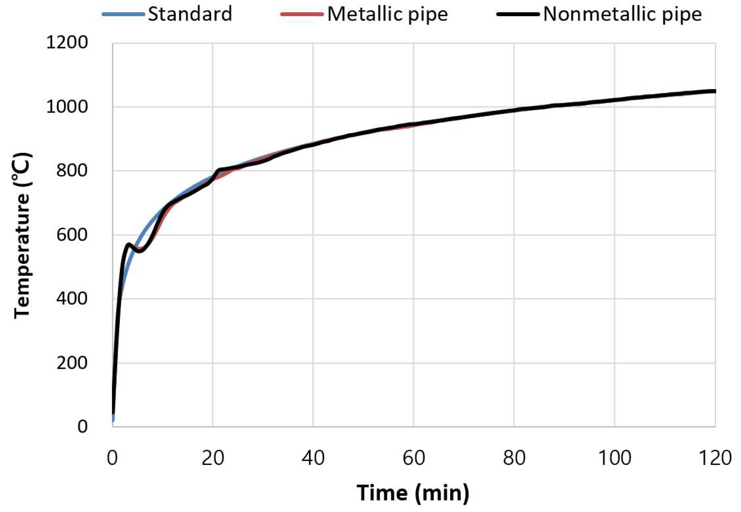
20]. The applied heating condition conformed to the ISO 834 standard temperature–time curve [
21], with furnace temperature controlled as a nonlinear function of time (Equation (1)). This theoretical curve is shown in
Figure 2 [
21] compared with the experimentally measured furnace temperature curves for both metallic and non-metallic pipe tests.
where
T is the temperature (in °C) and
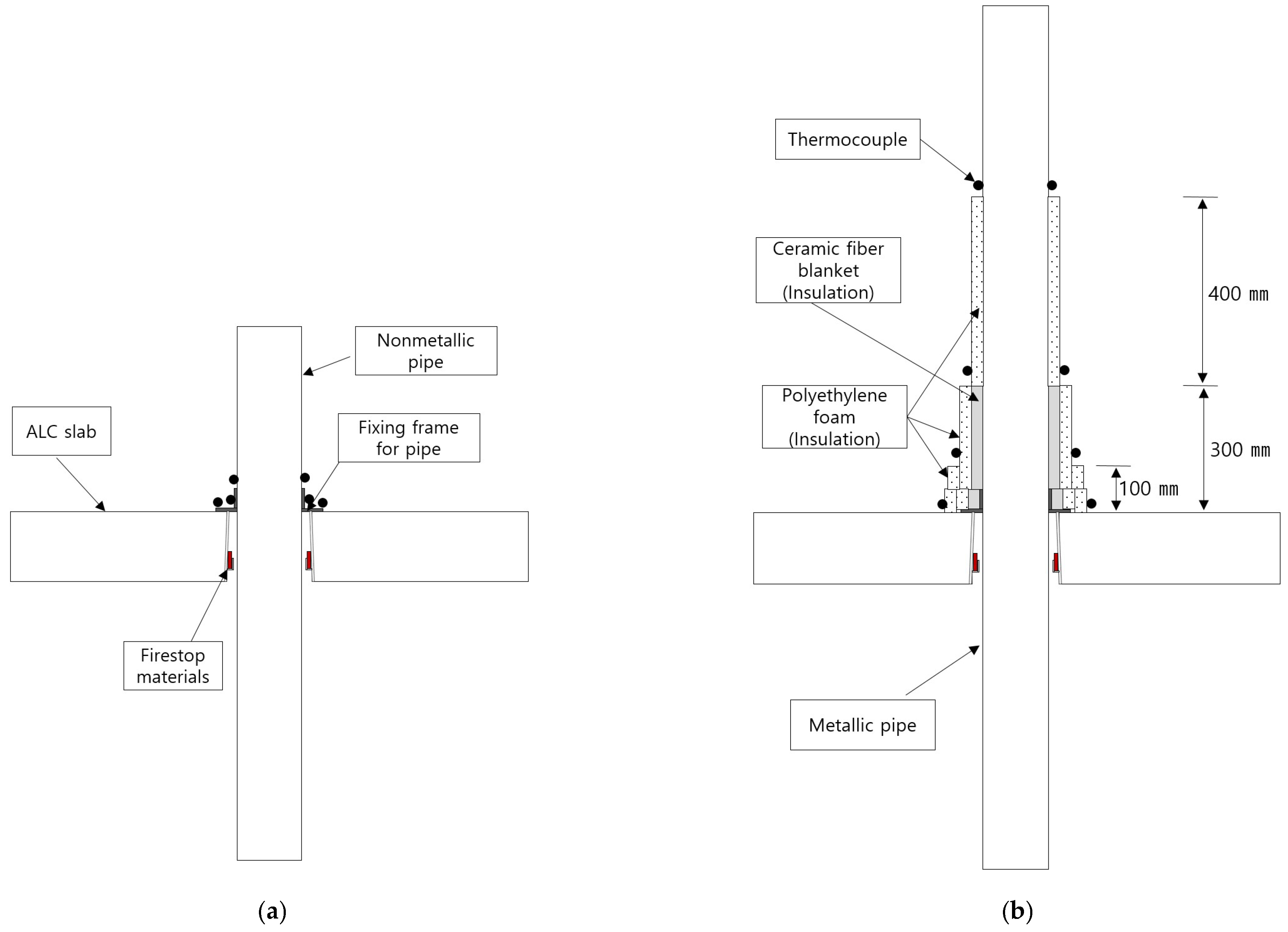
t is the time (in minutes). Experiments were conducted in a 4 m × 3 m horizontal furnace, with metallic and nonmetallic pipe specimens installed and evaluated independently. The specimen configurations and thermocouple-attachment positions are shown in
Figure 3. All specimens featured a single-penetration design comprising a sleeve-integrated firestop and a mounting frame, installed in a 150 mm-thick autoclaved lightweight concrete floor slab. The firestop material whose volume was adjusted in this study, refers to the intumescent sealant applied circumferentially at the interface between the pipe and the slab. This is indicated by the red-shaded zone labeled “Firestop material” in
Figure 3 and is distinct from the insulation layers applied above the slab for metallic-pipe specimens. For penetrants, carbon-steel pipes conforming to KS D 3562 [
22] were used for metallic specimens, and unplasticized polyvinyl chloride pipes conforming to KS M 3404 [
23] were used for nonmetallic specimens. The exposed length of each pipe below the heated surface was fixed at 1000 mm.
The insulation materials used for the metallic-pipe specimens included both inorganic (ceramic fiber blankets) and organic (cross-linked polyethylene (PE) foam) types. The ceramic fiber blanket, a high-temperature insulation material, had a density of at least 96 kg/m
3 and a thermal conductivity of 0.090 W/(m·K) at an average temperature of 300 °C. The PE-foam insulation had a thermal conductivity below 0.043 W/(m·K). For metallic-pipe penetrations, the insulation was arranged as shown in
Figure 3b. At the slab surface around the pipe, a 25 mm-thick, 300 mm-high ceramic fiber blanket was installed; above this, a 25 mm-thick, 300 mm-high PE insulation layer was applied; a 25 mm-thick, 100 mm-high PE layer was then applied; and finally, a 25 mm-thick, 400 mm-high PE layer was installed above the ceramic blanket.
Thermocouple locations for measuring the unexposed surface were marked with black dots and attached to the specimens’ rear side, on the exposed faces of the insulation and the pipes. For nonmetallic specimens, two thermocouples were installed on each of the floor, mounting frame, and pipe—a total of six. The three-layer insulation fully enclosed the floor surface for metallic specimens; therefore, no floor thermocouples were used; instead, two thermocouples were placed at the bottom, middle, and top sections of the insulation, and on the metallic-pipe surface. All thermocouples used were K-type, capable of measuring up to 1200 °C with an accuracy of ±1.5 °C. Temperature data were automatically recorded at 1-min intervals by using a Yokogawa MV2000 (Yokogawa Electric Corporation, Tokyo Japan) data acquisition system, satisfying the requirements specified in KS F ISO 10295-1 [
20].
3. Experimental Results
3.1. Nonmetallic Pipe Penetrations
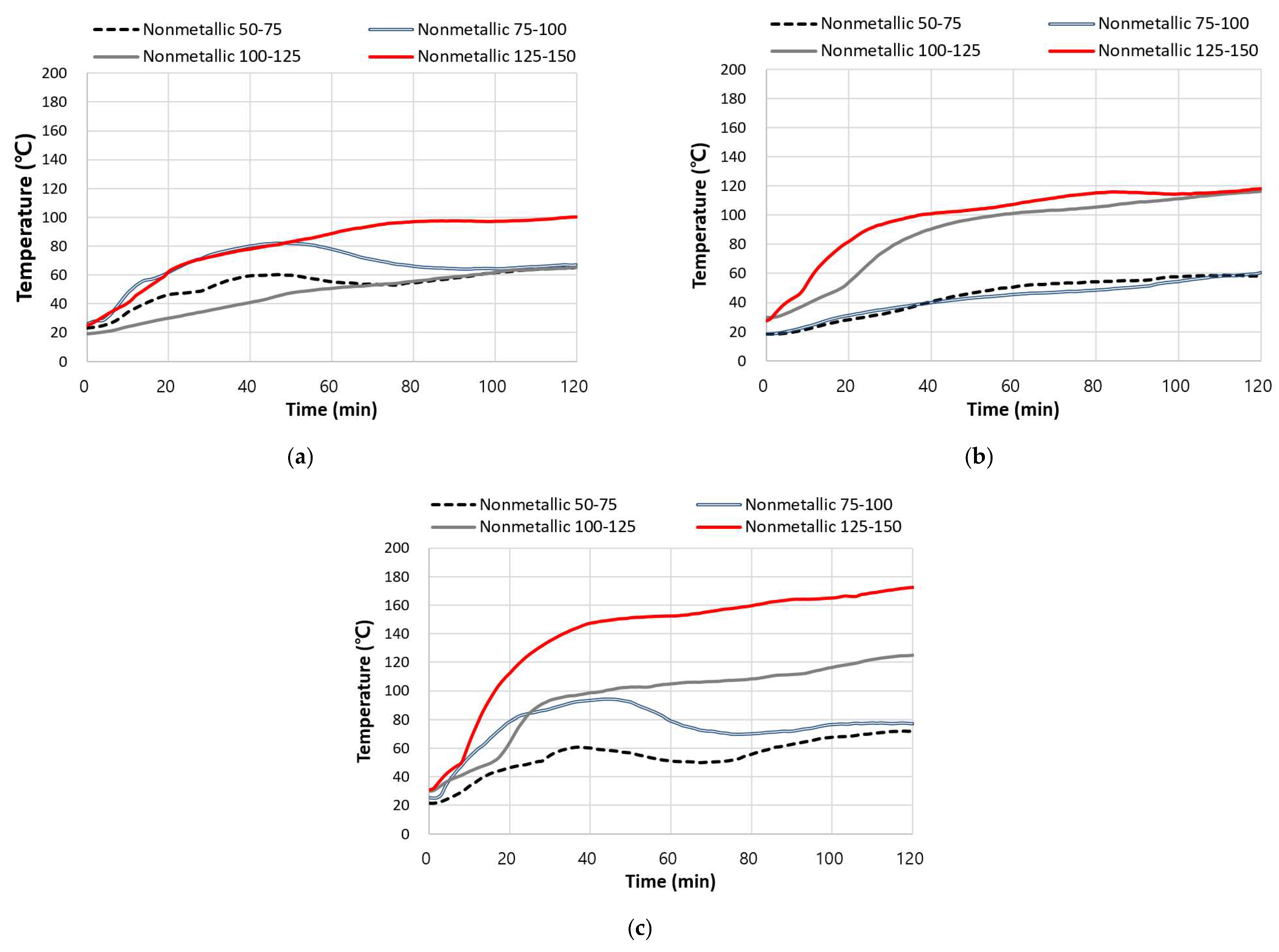
Figure 4 presents the fire-resistance test results for firestop systems used in nonmetallic pipe penetrations. In these specimens as described above, thermocouples were installed at the slab, mounting frame, and pipe, to measure the time–temperature response on the unexposed side. Penetrant and opening diameters were grouped into four nominal ranges (50–75 mm, 75–100 mm, 100–125 mm, and 125–150 mm), and the firestop-material volume was reduced proportionally as the opening size increased.
The slab area exhibited the most stable temperature distribution under all test conditions, with most readings remaining below 100 °C throughout the test. This stability is attributed to the slab’s horizontal orientation, which reduces direct radiant-heat exposure, and its relatively high thermal capacity, which suppresses temperature increases. However, in the 50–75 mm and 75–100 mm specimens, elevated initial temperatures occurred when the nonmetallic pipes softened and formed voids that were not immediately sealed by the firestop material. As the intumescent material expanded, these voids closed, and temperatures stabilized.
In the mounting frame area, heat concentration intensified with increasing opening diameter. This effect was especially pronounced when the penetrant diameter exceeded 100 mm, with temperatures approaching 120 °C. This junction between the pipe and slab is subject to complex interactions between the firestop-material density and thermal-stress concentration, making it a vulnerable zone where sealing performance may be weakened by delayed intumescent expansion or uneven material distribution.
The pipe area showed the highest temperature rise among all measurement points, reaching approximately 170 °C under the 125–150 mm condition. Rapid softening and collapse of the nonmetallic pipe formed internal voids that the firestop material could not seal fully, resulting in heat leakage. Similar findings by Sędłak [
11] indicate that the thermal-deformation properties of nonmetallic pipes can critically affect fire-resistance performance.
Nonetheless, all specimens remained below the 180 °C temperature-rise limit, suggesting that firestop material alone can provide sufficient thermal insulation. Despite nonmetallic pipes softening and thereby enlarging the penetration under high heat, effective fire resistance was still achieved with appropriate firestop-material distribution and intumescent expansion. This trend is further supported in subsequent sections, where the firestop-material distribution ratio is confirmed as a key performance variable.
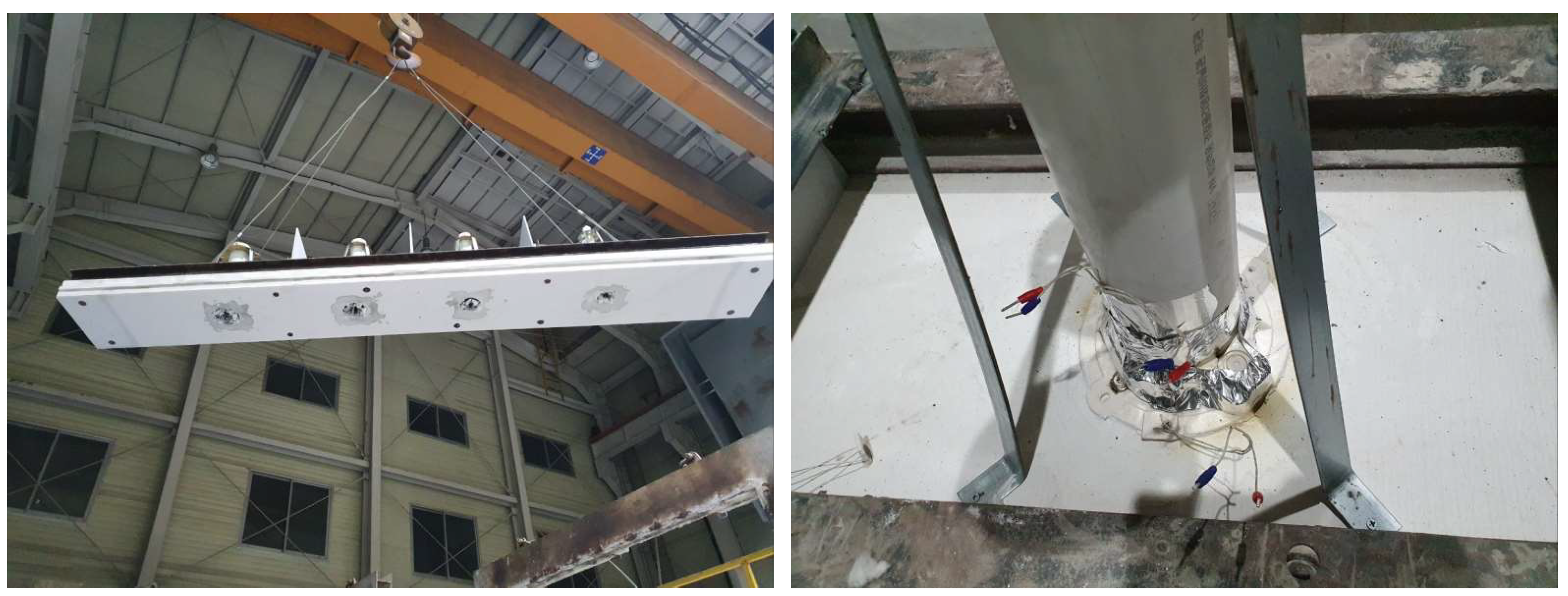
Figure 5 presents the post-test condition of the nonmetallic-pipe specimens. All penetrants remained structurally stable, with slight surface charring observed around some firestop interfaces.
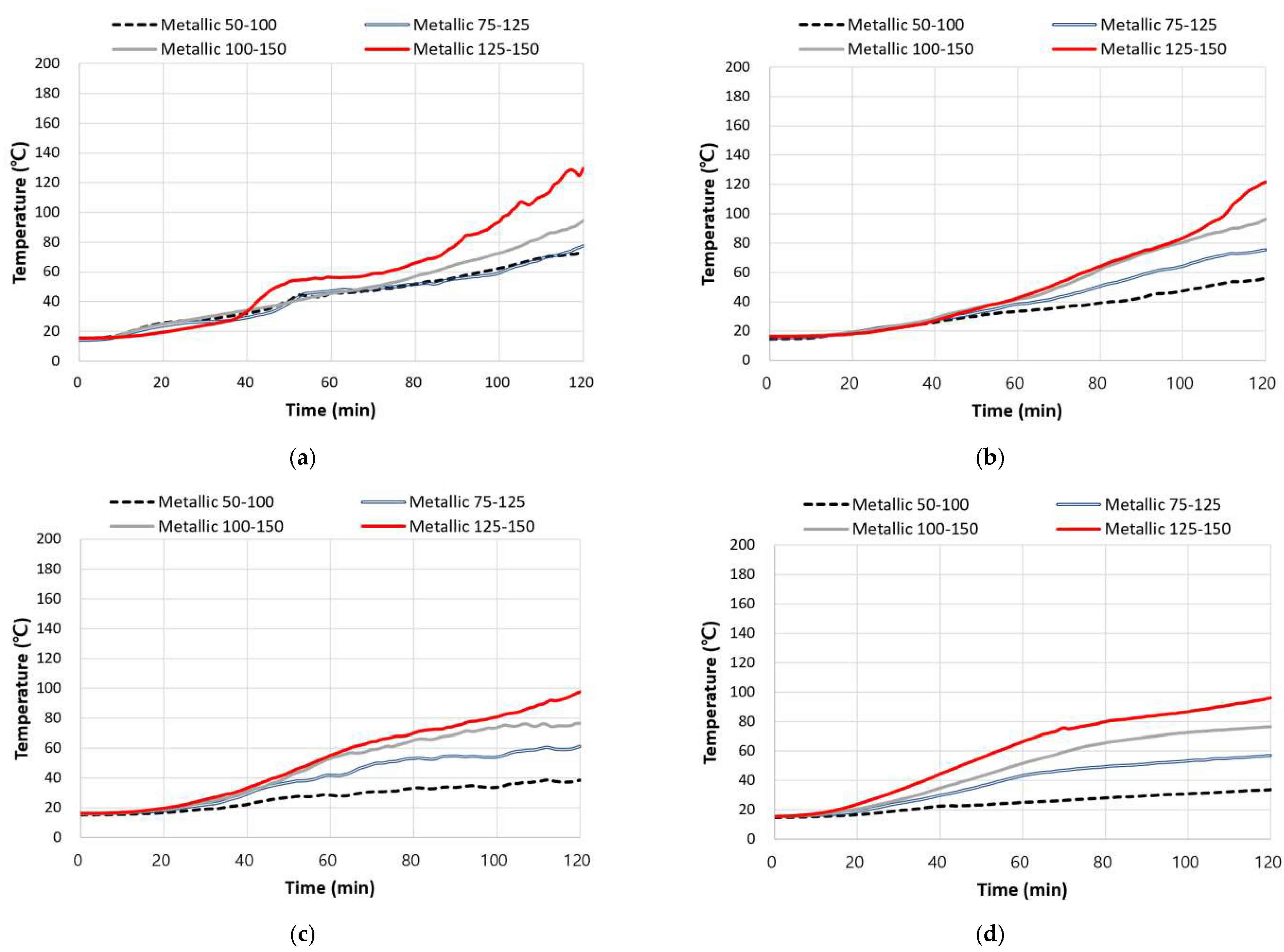
3.2. Metallic Pipe Penetrations
Figure 6 presents the fire-resistance test results for firestop systems applied to metallic pipes. Specimens were grouped into four opening–penetrant diameter conditions; in the final (125–150 mm) condition, only the pipe diameter increased while the opening remained fixed.
Overall, the lower thermocouples recorded the highest temperature rise, attributed to their proximity to the slab, where radiant heat arrives first. As measurements moved to the middle and upper layers, heat transmission was delayed, and the layered resistance of the composite insulation mitigated temperature increases. The insulated metallic-pipe surface remained below 100 °C throughout the test.
In the 125–150 mm condition, the increased pipe diameter reduced the available space for firestop and insulation materials, decreasing coverage of the thermal barrier. The larger cross-sectional area of the pipe also increased heat conduction, concentrating heat at the lower insulation interface. Consequently, the lower thermocouple recorded the greatest temperature rise, suggesting that, in metallic configurations, the penetrant thermal conductivity and cross-sectional area have more impact on fire-resistance performance than the opening size. This result indicates that in metallic-pipe configurations, the pipe’s size combined with the insulation material are major factors impacting heat transfer. These results align with the guidelines suggested by Gillespie et al. [
6]. Furthermore, the insulated pipe wall’s low temperature is attributed to both the insulation’s protective effect and heat dispersion over the pipe’s surface. Despite high-temperature exposure, the metallic pipe retained structural integrity without deformation, and the insulation effectively blocked radiant heat. This demonstrates that metallic pipe systems offer higher structural stability than nonmetallic ones and, when paired with an optimized insulation layer, achieve superior thermal-barrier performance.
Figure 7 shows the post-test condition of the metallic-pipe specimens. The insulation remained in place without visible failure, although slight surface charring was observed in some areas near the pipe-insulation interface.
3.3. Effect of the Volume of Firestop Material
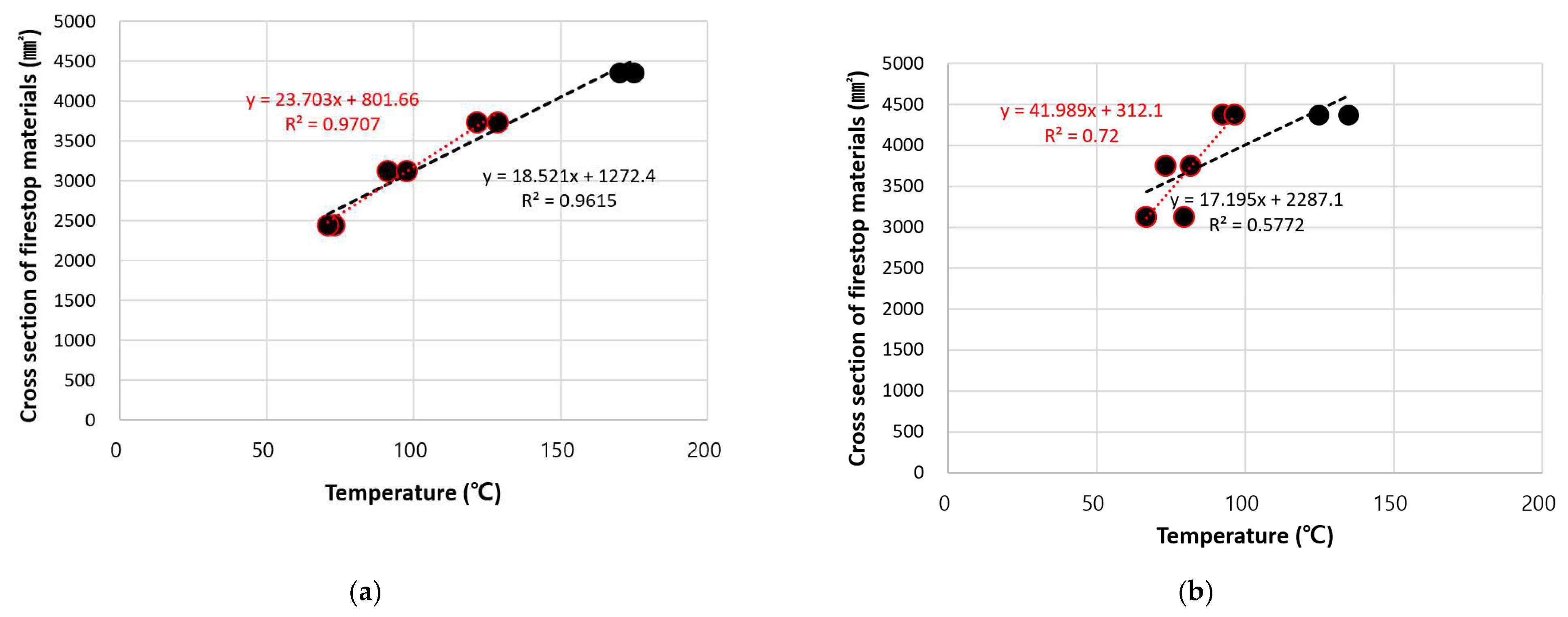
Figure 8,
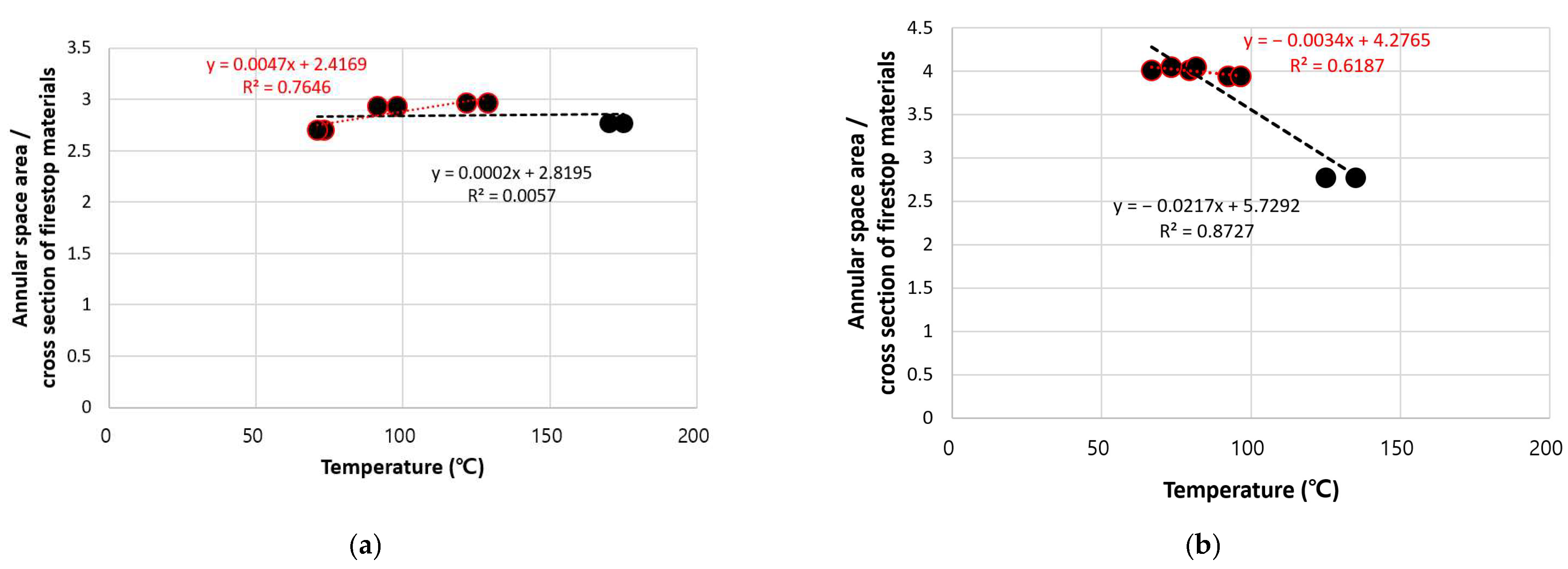
Figure 9 and
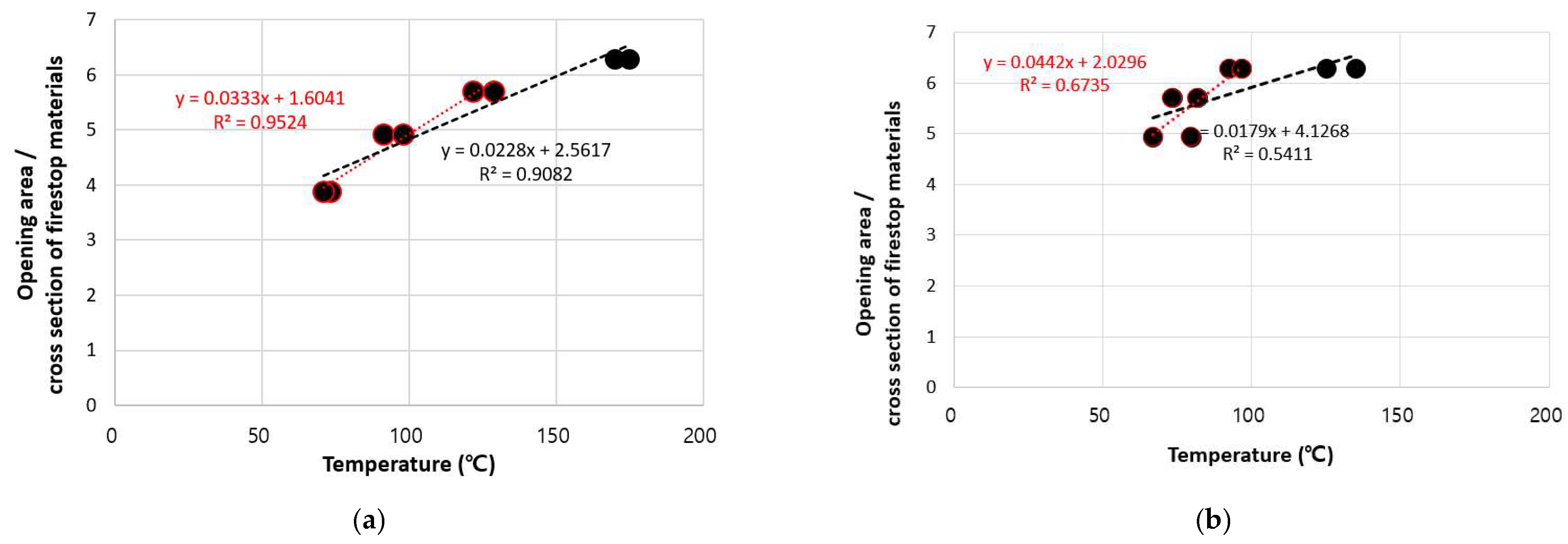
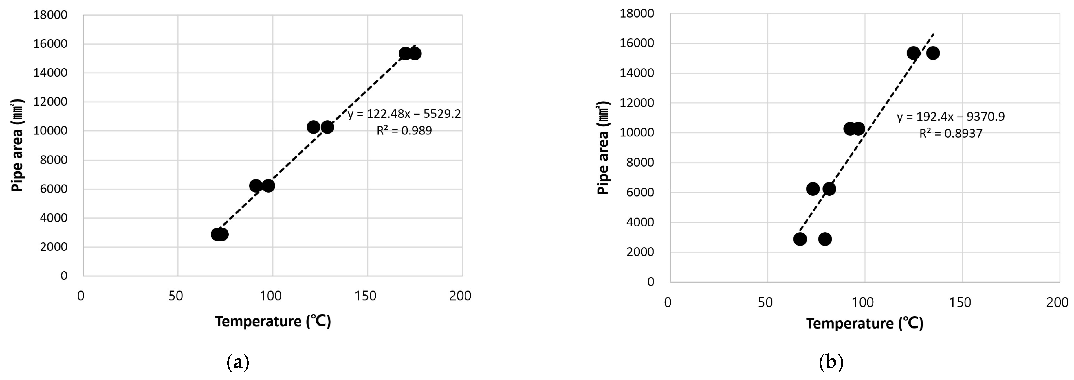
Figure 10 show the peak temperature as a function of the firestop-material cross-sectional area under three criteria: opening area, net fill ratio (firestop area minus penetrant area), and firestop-to-opening area ratio. Although nominal diameter combinations such as 50–100 mm, and 75–125 mm defined the test conditions, all area values in the graphs and analysis were calculated from measured outer diameters to reflect actual cross-sectional areas. Each graph entails a red line representing data excluding the 125–150 mm condition and a black line representing all data. For nonmetallic pipes, the red line includes the 50–75, 75–100, and 100–125 mm conditions; meanwhile, for metallic pipes, it includes the 50–100, 75–125, and 100–150 mm conditions. This comparison helps visualize the influence of the 125–150 mm condition in both material types. To visually distinguish the two trendlines, data points used for the red line are marked in red outline, while all data points are denoted as black-filled circles.
Figure 8 shows the peak temperature as a function of the absolute firestop-material area. For nonmetallic pipes, both lines excluding and including the 125–150 mm condition, exhibit a strong positive correlation: the peak temperature increases as the firestop material volume increases. This indicates that the firestop material volume is a critical determinant of fire-resistance performance in nonmetallic systems. In contrast, for metallic pipes, the correlation coefficient drops sharply. Even though the firestop volume is larger relative to the available space, the peak temperature rises, confirming that the pipe’s thermal conductivity and structural role outweigh the firestop volume in influencing fire resistance.
Figure 9 analyzes the peak temperature as a function of the net fill ratio. For nonmetallic pipes, the correlation coefficient collapses when the 125–150 mm condition is included, revealing low to near-zero correlation. This is because nonmetallic pipes soften and collapse at high temperatures, so that the pipe opens before it becomes sealed by expanded intumescent material; thus, the initial annular gap is not a critical factor in fire-resistance performance. By contrast, metallic pipes retain their structural continuity and conduct heat directly. The net fill ratio remains influential.
Figure 10 shows the peak temperature as a function of the firestop-to-opening area ratio. For nonmetallic pipes, both lines show strong negative correlations indicating that the extent of opening coverage directly influences fire resistance. For metallic pipes, correlations are weaker as heat is conducted through the pipe, which limits the explanatory power of firestop ratios based solely on opening size. The trendline slope for metallic systems also shifts considerably with the inclusion of the 125–150 mm condition, indicating the amplified heat-transfer effect of larger pipe diameters.
In summary, nonmetallic pipes exhibit a direct relationship between the extent of firestop application and fire resistance, owing to pipe collapse at high temperatures, requiring complete sealing by intumescent materials. Meanwhile, metallic pipes maintain their structure and conduct heat directly; thus, firestop material alone cannot ensure sufficient fire resistance—dedicated thermal insulation design is essential. These results further suggest that reducing the firestop volume is feasible for smaller penetrations, as peak temperatures remain constant or even decrease when the firestop-to-opening ratio drops from approximately 95% to 91%. This trend may be related to more effective expansion of the intumescent material in narrower annular gaps, or to a reduction in the available heat-transfer path through the penetration as the opening size decreases. These potential mechanisms require further verification through additional experiments. These observations suggest that more flexible volume-based criteria could be considered for small openings.
3.4. Effect of the Opening and Penetrant Size
Figure 11,
Figure 12 and
Figure 13 analyze the effects of the opening area, penetrant area (based on measured outer diameter), and actual solid cross-sectional area of the penetrant (outer diameter minus inner diameter) on peak temperature. The analysis distinguishes between nonmetallic and metallic pipes, and all dimensional values are based on actual measured areas derived from outer diameters. The focus was on comparing response patterns when one variable remained constant (either opening size or penetrant size) while the other varied.
Figure 11 shows how the peak temperature changes with opening area. For nonmetallic pipes (
Figure 11a), the peak temperature increased linearly with the opening area, maintaining high correlations. When exposed to high temperatures, nonmetallic pipes soften and collapse turning the entire opening into a heat-entry point; consequently, the heat-blocking performance of the firestop material is the determining factor in fire resistance. Thus, for nonmetallic pipes exposed to high temperatures, fire-resistance performance is more strongly influenced by the size of the opening to be sealed than by the size of the penetrant itself. However, in conditions where both opening size and penetrant size increase together, this statistical relationship may give the impression that the pipe’s size has a greater influence. In practice, because nonmetallic pipes are destroyed by high temperatures and no longer function structurally, this cannot be interpreted as a structural contribution. Meanwhile, for metallic pipes (
Figure 11b), the influence of opening area on performance was less significant, with lower correlation coefficients. Under conditions where the pipe diameter increased while the opening remained constant, the peak temperature rose, and the slope of the trendline gradually decreased. This indicates that metallic pipes, which maintain structural integrity, function as direct heat-transfer paths, and thus pipe diameter, rather than opening size, plays the more decisive role in determining fire resistance.
Figure 12 shows the peak temperature as a function of the penetrant area (based on actual outer diameter). For nonmetallic pipes (
Figure 12a), a high correlation was observed, however, this arises from the experimental linkage between the pipe and opening sizes. Because nonmetallic pipes disintegrate at high temperatures and no longer influence the heat-transfer structure, the size of the pipe itself has a minimal direct effect. In contrast, for metallic pipes (
Figure 12b), while the correlation coefficient was lower, it reflects a more meaningful structural relationship. As the penetrant area increases, the heat-conduction path expands, and even under constant opening conditions, the peak temperature rises accordingly.
Figure 13 analyzes the peak temperature as a function of the solid cross-sectional area of the penetrant. For nonmetallic pipes (
Figure 13a), a high linear correlation was again observed, but—as with previous findings—this is caused by coupling with the opening size increases rather than any physical influence. In contrast, metallic pipes (
Figure 13b) also showed a strong correlation with the penetrant solid area, confirming that as the outer diameter increases, the solid cross-section increases proportionally, expanding the heat-transfer path and causing an increase in the peak temperature.
Thus, the fire-resistance performance of nonmetallic pipes is highly dependent on opening size, with effectiveness determined by how well the firestop material seals the entire opening. The size or cross-sectional area of the penetrant has a minimal effect on performance when the pipe loses its structure, consistent with earlier findings in
Section 3.3 that firestop coverage and distribution ratio are key performance variables. Meanwhile, for metallic pipes, where the heat-transfer path remains intact, the penetrant area and solid cross-section act as direct determinants of performance loss, showing a clearer correlation than only the opening size or firestop volume. This trend was consistently observed even under experimental conditions where only the pipe size varied while opening size remained unchanged.
4. Conclusions
This study experimentally analyzed differences in fire-resistance performance by adjusting the volume of firestop material in response to variations in penetrant and opening sizes for both metallic and nonmetallic pipes. The analysis was based on cross-sectional areas calculated from measured outer diameters, enabling quantitative comparisons among opening size, penetrant size, and firestop material volume. The influence of each component on fire-resistance performance was also classified and interpreted according to penetration type. The major conclusions are as follows:
When the opening size was reduced, accompanied by a proportional decrease in firestop application area, the peak temperature either decreased or remained similar; no negative impact on fire-resistance performance was observed. This indicates that the current standard requiring a fixed amount of firestop material may be excessive for small penetrations, and that flexible application is feasible depending on conditions.
For nonmetallic pipes, which soften or collapse under high temperatures, fire-resistance performance was strongly influenced by total opening area and the degree of infill. Although an increase in penetrant area coincided with rising temperatures, this was due to experimental conditions in which both opening and penetrant sizes increased simultaneously. The penetrant size itself was unlikely to have been a major factor due to the pipe collapse at high temperatures. The impact of firestop volume was quantitatively evident in certain conditions.
For metallic pipes, which retain structural continuity and serve as direct heat-conduction paths, fire-resistance performance was more directly influenced by penetrant area or solid cross-section than by the opening size. Even under identical opening conditions, increasing the pipe size led to higher peak temperatures, empirically demonstrating that pipe diameter plays a critical role in determining fire resistance in metallic systems.
This study provides experimental evidence identifying and analyzing structural factors that influence fire-resistance performance for both metallic and nonmetallic firestop configurations under several different conditions. Future research will investigate whether the outer cross-sectional area or actual solid cross-sections of metallic penetrants more directly impact fire performance. This will help establish differentiated performance-evaluation criteria based on penetration shape and component configuration. The findings are expected to serve as empirical data to enhance the stability and effectiveness of performance-based design standards and certification systems for firestop assemblies.
This study did not aim to define the minimum possible volume of firestop material, but rather to evaluate whether sufficient performance could be secured through a simplified application method—specifically, with a single circumferential layer around small penetrations. With further accumulation of data with progress in research, this approach may lead to generalized volume criteria and potentially support the development of simplified predictive formulae for performance-based design.
The present study also has certain limitations. Specifically, future work should consider additional variables that were not covered in this study. The use of other firestop materials such as mortars, putties, and wraps, different structural substrates beyond autoclaved lightweight concrete, and vertical installation orientations warrant investigation. These factors may significantly influence fire-resistance behavior and are important in the validation and generalization of the proposed approach.
Author Contributions
Conceptualization, H.-B.C. and J.-O.P.; methodology, H.-B.C. and J.-O.P.; software, H.-D.L. and S.-Y.H.; validation, A.-Y.J. and J.-O.P.; formal analysis, H.-B.C. and S.-Y.H.; investigation, A.-Y.J. and J.-O.P.; resources, A.-Y.J. and J.-O.P.; data curation, H.-B.C. and S.-Y.H.; writing—original draft preparation, H.-B.C.; writing—review and editing, A.-Y.J. and J.-O.P.; visualization, H.-D.L. and S.-Y.H.; supervision, A.-Y.J.; project administration, A.-Y.J.; funding acquisition, A.-Y.J. and J.-O.P. All authors have read and agreed to the published version of the manuscript.
Funding
This work was supported by the program “[Assessment and Certification] 2025 Building Material Accreditation Program—Firestop Systems (20250031)” funded by the Korea Institute of Civil Engineering and Building Technology.
Institutional Review Board Statement
Not applicable.
Informed Consent Statement
Not applicable.
Data Availability Statement
The raw data supporting the conclusions of this article will be made available by the authors on request.
Conflicts of Interest
The authors declare no conflicts of interest.
References
- Lee, E.P. Analysis of Causes of Casualties in Jecheon Sports Center Fire—Focus on Structural Factors of Buildin. J. Korea Inst. Fire Sci. Eng. 2018, 32, 86–94. [Google Scholar] [CrossRef]
- Promat. The Passive Fire Protection Handbook: The UK’s Comprehensive Guide to Passive Fire Protection. 2017. Available online: https://www.promat.co.uk/en/reference/fire-protection-handbook (accessed on 25 April 2025).
- Ye, Z.; Fleischmann, C.M.; Abu, A.K.; Pau, D. Estimation of effective thermophysical properties of firestopping sealants: Methodology and case study. Fire Saf. J. 2023, 141, 103928. [Google Scholar] [CrossRef]
- Izydorczyk, D.; Sędłak, B.; Sulik, P. Problematyka prawidłowego odbioru wybranych oddzieleń przeciwpożarowych. Mater. Bud. 2014, 11, 62–64. [Google Scholar]
- Sulik, P.; Sędłak, B. Badania odporności ogniowej dużych mieszanych uszczelnień przejść instalacyjnych. Mater. Bud. 2014, 7, 20–22. [Google Scholar]
- Gillespie, P.E.; O’Leary, P.E.; Mattes, B.; Talbot, J.; Neese, R.K.; Wasilewski, B. Technical Guideline on Through Penetration Firestopping. 2007. Available online: https://www.smacna.org/business-resources/resource/technical-guideline-on-through-penetration-firestopping (accessed on 25 April 2025).
- Sędłak, B.; Sulik, P.; Izydorczyk, D.; Łukomski, M. Fire-stop wraps and collars with intumescent materials—Performance comparison. Procedia Eng. 2017, 172, 961–968. [Google Scholar] [CrossRef]
- Kosiorek, M.; Laskowska, Z. Bezpieczeństwo pożarowe, Cz.17: Przejścia instalacyjne. Mater. Bud. 2007, 3, 83–88. [Google Scholar]
- Laskowska, Z. Temperatura uszczelnień przejść rur metalowych przez ściany i stropy w badaniach odporności ogniowej. Pr. Inst. Tech. Bud. 2008, 37, 19–32. [Google Scholar]
- Orzeł, F. Rozwiązania techniczne przejść instalacyjnych z uwagi na bezpieczeństwo pożarowe. Elektro Info 2009, 10, 42–45. [Google Scholar]
- Sędłak, B. Porównanie skuteczności działania opasek i kołnierzy ogniochronnych z materiałami pęczniejącymi. Izolacje 2013, 18, 63–68. [Google Scholar]
- Sędłak, B.; Sulik, P. Problematyka prawidłowego odbioru uszczelnień przejść instalacyjnych. Mater. Bud. 2015, 7, 44–46. [Google Scholar] [CrossRef]
- Cho, H.S.; Park, J.H.; Son, B.S.; Im, J.S. A study on assessment of penetration seals performance of nuclear power plants. Fire Sci. Eng. 2004, 18, 93–102. [Google Scholar]
- Lee, H.D.; Jeong, A.Y.; Choi, Y.J.; Seo, H.W.; Park, J.O. Standard supporting and F-class structures for improving the firestop recognition system. J. Korean Soc. Hazard Mitig. 2019, 19, 127–135. [Google Scholar] [CrossRef]
- Lee, J. Evaluation of Heat Insulation Material Performance Based on Firestop System Thermal Modeling. Ph.D. Thesis, Department of Architectural Engineering, Kwangwoon University, Seoul, Republic of Korea, 2022. [Google Scholar]
- Park, C.; Lee, J. Experimental study on the fire performance of firestop systems for through-penetrations in fire-rated walls. Fire Mater. 2019, 43, 412–426. [Google Scholar]
- ASTM E814; Standard Test Method for Fire Tests of Penetration Firestop Systems. ASTM International: West Conshohocken, PA, USA, 2021.
- UL 1479; Standard for Fire Tests of Through-Penetration Firestops. Underwriters Laboratories: Northbrook, IL, USA, 2021.
- Choi, D.H.; Park, J.H.; Lee, J.Y. Improvement plans for fire-resistant structures in buildings. J. Comput. Struct. Eng. 2011, 24, 23–31. [Google Scholar]
- KS F ISO 10295-1; Fire Tests for Penetration Seals—Part 1: Fire Resistance Test Method. Korean Agency for Technology and Standards (KATS): Seoul, Republic of Korea, 2021.
- KS F ISO 834-1; Fire-Resistance Tests—Elements of Building Construction—Part 1: General Requirements. Korean Agency for Technology and Standards (KATS): Seoul, Republic of Korea, 2022.
- KS D 3562; Carbon Steel Pipes for Pressure Service. Korean Agency for Technology and Standards (KATS): Seoul, Republic of Korea, 2021.
- KS M 3404; Unplasticized Polyvinyl Chloride (PVC-U) Pipes for Water Supply. Korean Agency for Technology and Standards (KATS): Seoul, Republic of Korea, 2021.
| Disclaimer/Publisher’s Note: The statements, opinions and data contained in all publications are solely those of the individual author(s) and contributor(s) and not of MDPI and/or the editor(s). MDPI and/or the editor(s) disclaim responsibility for any injury to people or property resulting from any ideas, methods, instructions or products referred to in the content. |
© 2025 by the authors. Licensee MDPI, Basel, Switzerland. This article is an open access article distributed under the terms and conditions of the Creative Commons Attribution (CC BY) license (https://creativecommons.org/licenses/by/4.0/).


