Abstract
This study investigated the feasibility and effectiveness of a commercial top-down stereolithography (SLA)-based system for the additive manufacturing of zirconia dental prostheses. Yttria-stabilized zirconia–resin slurries were prepared, and zirconia objects were fabricated using a top-down SLA system. Thermogravimetric–differential thermal analysis was used to examine the resin, while X-ray fluorescence spectroscopy and X-ray diffraction were used to analyze the printed samples. The microstructures of additively manufactured and subtractively manufactured zirconia were compared using field emission scanning electron microscopy (FE-SEM) before and after sintering. Biaxial flexural strength tests were also conducted to evaluate mechanical properties. The green bodies obtained via additive manufacturing exhibited uniform layering with strong interlayer adhesion. After sintering, the structures were dense with minimal porosity. However, compared to subtractively manufactured zirconia, the additively manufactured specimens showed slightly higher porosity and lower biaxial flexural strength. The results demonstrate the potential of SLA-based additive manufacturing for dental zirconia applications while also highlighting its current mechanical limitations. The study also showed that using a blade to evenly spread viscous slurry layers in a top-down SLA system can effectively reduce oxygen inhibition at the surface and relieve internal stresses during the layer-by-layer printing process, offering a promising direction for clinical adaptation.
1. Introduction
Additive manufacturing (AM), which is often associated with three-dimensional (3D) printing, presents promising advantages in the engineering of prototypes or customized physical objects with complex shapes [1]. Unlike traditional formative or subtractive manufacturing, additive manufacturing involves building objects layer-by-layer, enabling the creation of intricate and customized complex hybrid structures with precise design specifications without the need for an expensive framework [2]. Additive manufacturing has been applied to process numerous different materials, such as resin polymers, metals, ceramics, and soft materials for bio-applications [3]. Additive manufacturing has shown significant potential for customizing dental implants and other dental tools owing to its versatility and adaptability [4].
In dentistry, dental prostheses play a major role in improving oral health and esthetics. The properties of ceramic prostheses make them desirable for dental applications. Ceramic prostheses offer several advantages in terms of esthetics, mechanical properties, biocompatibility, and cost [5]. Ceramic prostheses, such as dental crowns, bridges, and implants, are now common alternatives to metals [6]. In dentistry, the development of technologies for computer-aided design (CAD) and computer-aided manufacturing (CAM (CAD/CAM) systems, such as digital scanners and milling systems, has enabled the fabrication of ceramic prostheses [7]. High-strength ceramic prostheses, fabricated using zirconia and lithium disilicate, are often milled as pre-sintered blocks and then sintered to fabricate prostheses with excellent mechanical properties [8]. However, there are several disadvantages associated with the fabrication of zirconia-based ceramic prostheses using CAD/CAM systems that are based on subtractive manufacturing procedures, such as the generation of milling dust and limited design flexibility [9]. Recently, the additive manufacturing of ceramic prostheses for dental applications has emerged as a technique with great potential. Systems based on additive manufacturing have been developed for fabricating zirconia-based ceramic prostheses; however, they still need to overcome limitations to be accepted for clinical use. The main problem associated with additively manufactured zirconia is its low mechanical strength compared to that of conventionally manufactured zirconia using subtractive manufacturing [10].
The use of zirconia in dentistry is increasing to meet the growing demands for esthetic treatments. High-density zirconia is required for dental applications to achieve excellent mechanical properties and high translucency. For better esthetics, high-transmittance zirconia with low alumina and a high yttria content has been developed for dental applications. Commercially available zirconia is commonly doped with 0.25 wt.% alumina [11]. For the fabrication of high-density zirconia, alumina is of particular importance as a contaminant because it improves the densification rate of zirconia; however, it reduces the transmission of visible light owing to the segregation of alumina on zirconia grain boundaries [12,13]. In 2011, high translucent tetragonal zirconia polycrystalline (TZP) stabilized with 3 mol% of yttria containing less than 0.05 wt.% alumina was introduced into dentistry. Although reducing the amount of alumina to less than 0.05% can contribute to increasing translucency, it degrades the mechanical properties [14].
Dental prostheses not only restore functionality such as occlusal support and protection but also require esthetics to meet patient expectations. The high transparency of zirconia is particularly crucial for achieving natural esthetics in prosthetic restoration. For additive manufacturing, several processes have been developed, including binder jetting, material extrusion, powder bed fusion, and polymerization processes such as stereolithography (SLA) and digital light processing (DLP) [15]. Each method has its advantages and disadvantages [16]. Several additive manufacturing systems are commercially available for the production of dental restorations [17,18]. The zirconia ceramic slurry composition used in the additive manufacturing process influences the overall quality of the final restorations. The ceramic grain sizes in zirconia objects fabricated using commercial additive manufacturing systems negatively impact the mechanical properties and density. As a result, zirconia ceramic restorations fabricated via additive manufacturing have fewer desirable properties than those fabricated via subtractive manufacturing.
The most commonly used processes for 3D modeling ceramics are SLA and DLP [19,20]. The systems based on these processes involve the creation of layers in either bottom-up or top-down approaches. In the bottom-up approach, the build platform begins at the bottom of the resin container and moves upward as each layer is cured. A light source, such as a projector for DLP or laser for SLA, cures the resin through a transparent window at the bottom of the container. In the top-down approach, the build platform begins at the top of the resin container and moves downward as each layer is cured. A light source cures the resin layer-by-layer from the top. While both bottom-up and top-down approaches have their advantages and limitations, the top-down approach is preferred in contexts where speed, efficiency, and reduced risk of print failures are critical factors [21]. The top-down approach has comparatively faster printing times because the object is continuously pulled out of the resin rather than being built layer-by-layer from the bottom. In the top-down approach, the object being built is not subjected to the peeling forces that the bottom-up approach involves while building each layer, and the risk of printing failures, such as detachment from the build platform, is reduced.
In this study, we explored a commercial top-down SLA-based system for the additive manufacturing of ceramic prosthetic restorations. This SLA-based system can use formulated resin–ceramic slurries for the fabrication of ceramics. Relatively viscous slurries can be spread thinly with blades; however, if the viscosity is too high, it becomes difficult to uniformly spread the slurries. After the slurry is spread, it is photopolymerized. However, if the polymerization shrinkage is large, it causes deformation of the polymerized area, making layer formation difficult. Therefore, both the slurry and modeling conditions require optimization. We used 0.05 wt.% alumina and 3 mol% yttria-stabilized tetragonal zirconia polycrystalline (Y-TZP) because these values have been found to be suitable for fabricating dental crowns [22]. Further, we investigated the feasibility and effectiveness of the SLA-based system for fabricating dental zirconia prostheses. This study aims to overcome the current challenges and broaden the applications of additive manufacturing in clinical practice.
2. Materials and Methods
2.1. Materials and Particle Size Distribution
The particle size distribution of the commercially purchased 0.05 wt.% alumina and 3 mol% yttria-stabilized zirconia (HSY–3F-J-LA, Daiichi Kigenso Kagaku Kogyo Co., Ltd., Osaka, Japan) was determined using a laser diffraction particle size analyzer (SALD-2300, Shimadzu, Kyoto, Japan). Milli-Q ultrapure water was used as the dispersion medium, and 0.1% sodium hexametaphosphate was used as the dispersant. Particle dispersion was performed via ultrasonication to achieve uniform dispersion.
To prepare yttria-stabilized zirconia (HSY–3F-J-LA)–resin (zirconia–resin) slurry, an ultraviolet (UV)-curable resin (SKFine; Kusatsu, Japan) was prepared and used. Next, a 46 vol% zirconia–resin slurry was prepared for use in additive manufacturing. The reason for choosing 46 vol% is provided in the discussion section.
2.2. Thermogravimetry–Differential Thermal Analysis (TG–DTA)
For TG–DTA analysis (ThermoPlus, TG8110, Rigaku Co., Tokyo, Japan), the UV curable resin samples were heated to 1000 °C from approximately 25 °C at a heating rate of 5 °C/min.
2.3. Additive Manufacturing of Zirconia
Additive manufacturing samples were produced using a stereolithography system (SZ-2500, SK Fine, Kusatsu, Japan) equipped with a 355 nm UV laser. The continuous stereolithography process is schematically shown in Figure 1d. Cross-sectional features are continuously formed by laser drawing on a slurry layer applied to the stage, and the material is solidified by photo-polymerization. Layers are stacked under optimized lithographic conditions, and solid objects are successfully produced. Laser diameter and layer thickness were set to 50 µm, laser power was set to 150 mW, and laser scanning speed was set to 2000 mm/s. A disk geometry with a height of 1.6 mm and a base diameter of 21 mm was produced. The sample in its pre-degreased state is called the green body. It was then de-bound and sintered at 1450 °C. The sintered specimen is referred to as sintered additively manufactured zirconia.
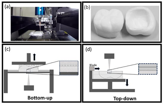
Figure 1.
(a) A 3D printer for the additive manufacturing of the top-down SLA-based system (SZ2500; SK Fine, Kyoto, Japan). (b) Additively manufactured zirconia crowns. Schematics showing the (c) bottom-up and (d) top-down approaches used in SLA 3D printers. (c) In the bottom-up approach, the slurry is spread thinly, and light is irradiated from below to cure it. This method ensures efficient polymerization because the slurry tank and the slurry are in close contact. However, when the cured object is lifted, a force is applied to separate it from the slurry tank. Additionally, the absence of an uncured layer between successive slurry layers can lead to the formation of bubbles. (d) In the top-down approach, the slurry is spread, and light is irradiated from above to cure it. In this method, the topmost layer of the slurry is exposed to the atmosphere, which inhibits polymerization and forms an uncured layer. As the cured object moves downward and the next slurry layer is spread, this uncured layer mixes with the new layer. Subsequently, polymerization progresses, resulting in strong bonding between layers.
2.4. Subtractive Zirconia Preparation
For subtractive zirconia, semi-sintered commercial subtractive zirconia (ZircoArt, Denken High Dental, Kyoto, Japan) was used. Subtractively manufactured semi-sintered zirconia was sintered at 1450 °C for 2 h according to the manufacturer’s instruction.
2.5. X-Ray Fluorescence Spectroscopy (XRF)
The chemical compositions of various elements and oxides present in sintered additively manufactured zirconia and sintered subtractive zirconia were measured by XRF.
The XRF data were recorded using an EDX-7200 instrument from SHIMADZU (Kyoto, Japan). The PCEDX Navi (Version: EDX-7000P) software was used for recording, processing, and analyzing XRF data.
2.6. X-Ray Diffraction (XRD)
The crystal phases of the sintered additively manufactured zirconia and subtractively sintered zirconia were identified using XRD data recorded with an X-ray powder diffractometer (RINT 2500, Rigaku, Tokyo, Japan) equipped with a CuKα radiation source (λ = 1.5406 Å), operated at 40 kV acceleration and a current of 200 mA. The XRD patterns were recorded in the 2θ/θ geometry at a scanning rate of 0.02 s−1. The XRD patterns were compared with those in the Rigaku ICDD database.
2.7. Field Emission Scanning Electron Microscopy (FE-SEM)
For cross-sectional SEM observations, four different groups, including the green body, sintered additively manufactured zirconia, subtractive semi-sintered, and sintered zirconia, were prepared using a cross-sectional polisher (SM-09020CP Cross-Section Polisher, JEOL, Tokyo, Japan). Subsequently, a thin layer of carbon was deposited on their surfaces (SC-701CT, Sanyu Electron, Tokyo, Japan) to minimize sample charging. The specimens were examined using an FE-SEM (JSM-6701F, JEOL) operated at 5 kV, and the data were captured using an annular semiconductor detector.
2.8. Biaxial Flexural Strength Testing
For biaxial flexural strength testing, ten specimens, each from the additive manufacturing and subtractive groups, were used. The biaxial flexural strength was determined by performing piston-on-3-balls (P3Bs) testing on mirror-polished ceramic samples (1.4 mm diameter × 1.2 mm) according to the ISO, standard 6872:2015 [23]. All tests were conducted using a universal machine (Shimadzu) at a crosshead speed of 1 mm/min.
The yielding loads at fracture (P in Newton) were recorded, and the corresponding Brazilian failure strengths (σ in MPa) were then calculated using the following equation:
where X = (1 + ν) ln(r2/l)2 + [(1 − ν)/2] (r2/l)2 and Y = (1 + ν) (1 + ln(r1/l)2) + (1 − ν) (r1/l)2, “b” is the specimen’s thickness at the fracture origin (in mm); “ν” is Poisson’s ratio (0.25 for dental ceramics); r1 is the radius of the support circle (in mm); r2 is the radius of the loaded area (in mm); and r3 is the radius of the specimen (in mm).
σ = −0.2387 P(X − Y)/b2,
The data were analyzed using an independent samples t-test (SPSS, V25, Chicago, IL, USA). A significance level (α) of 0.05 was used as the cutoff for significance.
3. Results
3.1. TG–DTA Analysis
According to the TG–DTA curve presented in Figure 2a, the pyrolysis of prepared resin samples led to weight loss. The change in mass of the resin with a temperature change from room temperature to 580 °C occurred in three steps and corresponded to different decomposition processes. The first step occurred below 230 °C, with a weight loss of 10%. The second step occurred in a temperature range of 230–500 °C, with a total weight loss of 80%. After reaching 500 °C, another significant weight change was observed.
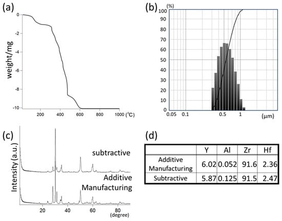
Figure 2.
(a) Thermal analysis of UV-curable resin used for additive manufacturing. (b) Particle size distribution of 3 mol% Y2O3-stabilized ZrO2. (c) XRD patterns and (d) XRF analysis of chemical compositions of additively manufactured sintered zirconia and subtractive zirconia.
3.2. Particle Distribution
As shown in Figure 2b, the histogram showing the particle sizes of the HSY–3F-J-LA zirconia sample used for additive manufacturing indicates that the average particle size was 500 nm (300–1000 nm).
3.3. XRF
The XRF results obtained revealed the amounts of Al2O3, Y2O3, and HfO2 in the zirconia samples (Figure 2d). Compared to subtractive zirconia (0.125 wt.%), the HSY–3F-J-LA sample contained a lower Al2O3 content (0.052 wt.%). The HSY–3F-J-LA sample contained 6.01 wt.% Y2O3 and 2.36 wt.% HfO2, whereas the CAD/CAM subtractive zirconia sample contained 5.87 wt.% Y2O3 and 2.47 wt.% HfO2.
3.4. XRD
Figure 2c shows the XRD patterns of sintered subtractive and sintered additively manufactured zirconia ceramics in a 2θ range of 20–80°. Both samples exhibited similar XRD patterns related to the tetragonal crystal structure of Y-TZP ceramics, indicating the presence of zirconia in the tetragonal phase. The main XRD peak was detected at approximately 30.21°, indicating a predominant tetragonal zirconia phase for both zirconia.
3.5. SEM
The SEM of the green body of additively manufactured zirconia revealed a uniform microstructure (Figure 3a,b). The high magnification of the SEM image revealed that approximately 500 nm-sized zirconia particles were dispersed in resin (Figure 3c,d).
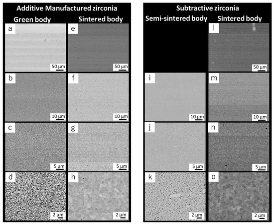
Figure 3.
Cross-sectional SEM images at various magnifications of additively manufactured zirconia. ((a–d) Green body and (e–h) sintered) and subtractive zirconia; ((i–k) semi-sintered and (l–o) sintered).
The sintered additively manufactured zirconia exhibited a dense structure with only a few pores (Figure 3e–h). The grains are shown in the high-magnification images. Analysis revealed that the grain size of additively manufactured, sintered zirconia was approximately 1–2 μm. Several pores were observed between the grain boundaries (Figure 3h).
The microstructure of the semi-sintered subtractive zirconia revealed an approximately uniform structure (Figure 3i–k); however, a few large-sized particles of zirconia can be observed (Figure 3k). The SEM image of the sintered subtractive zirconia revealed the presence of dense structures with only a few pores (Figure 3h,o). A high-magnification image of the sintered subtractive zirconia revealed the presence of fewer pores compared to the additively manufactured sintered zirconia. The grain size was approximately 1–2 μm (Figure 3o).
3.6. Biaxial Flexural Strength Testing
When compared to the additively manufactured zirconia, the CAD/CAM zirconia exhibited no statistically significant difference in strength (Figure 4). The biaxial flexural strength data for additively manufactured zirconia had a larger standard deviation.
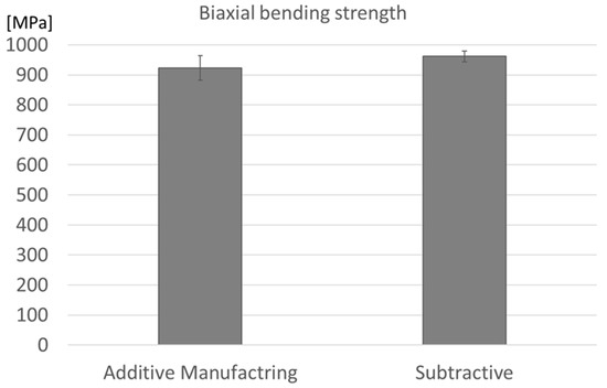
Figure 4.
Biaxial flexural strength of zirconia fabricated by additive and subtractive manufacturing methods. Error bars represent standard deviations (SDs). No statistically significant difference was found between the two groups (p > 0.05).
4. Discussion
Generally, a dental subtractive zirconia block is subjected to high pressures prior to semi-sintering, which increases porosity and degrades mechanical properties. However, during the additive manufacturing of zirconia, in general, there are no processes involving the application of pressure to the zirconia object [24]. To enhance the mechanical properties of zirconia, we explored a novel top-down SLA system for fabricating dental zirconia laminates. The resulting additively manufactured zirconia had fewer pores and exhibited an almost homogeneous structure without any layer-by-layer distinction. However, the sintered zirconia had a lower mechanical strength, relatively close to that of subtractive zirconia fabricated via subtractive manufacturing.
For additive manufacturing using SLA-based systems, the resin composition used for preparing the slurries is also important for obtaining highly dense ceramics [5,25]. We prepared a UV-curable acrylate based on a low-viscosity resin containing several acrylate monomers. The TG–DTA data indicated a weight loss at 230 °C in the range of 230–500 °C. Therefore, de-binding was carried out for up to 600 °C. Jang et al. examined the use of 48–56 vol% zirconia-added slurries. They demonstrated that the higher the zirconia concentration in a slurry, the higher the strength. However, a slurry with a high concentration of zirconia has a high viscosity, making printing difficult [26]. The zirconia concentration increased further; however, small scratches were made when spreading the zirconia slurry by the blade; therefore, we adjusted it to 46 vol% to improve spreading behavior.
Cross-sectional SEM analysis of the green body of additively manufactured zirconia revealed the presence of white lines, separated by approximately 50 µm, which is consistent with the paste layer’s thickness. This can be attributed to the different compositions of the zirconia particles and resin, possibly because heavy zirconia particles can sink into the slurry. The high-magnification SEM image of the green body revealed that the zirconia particles were well distributed. After sintering, the low-magnification SEM image did not have lines in the green body. The sintered additively manufactured zirconia did not contain alumina particles, similar to the subtractive zirconia. Both the additive and subtractive manufacturing of zirconia involved zirconia with a low alumina content. SEM observations revealed that the additively manufactured zirconia obtained after sintering exhibited small holes; however, its density was almost the same as that of the subtractive zirconia fabricated via subtractive manufacturing.
Although multiple SEM images were taken for each specimen, SEM is a localized surface analysis technique, and its primary purpose in this study was to qualitatively compare representative microstructural features. Therefore, the statistical evaluation of features such as porosity or grain size distribution was not applicable in this context.
The biaxial bending strengths of additive and subtractive manufactured zirconia were almost identical. This result is consistent with the SEM observations. Improving the density of zirconia is important for achieving desirable mechanical properties. In general, subtractive zirconia is prepared via compression molding. Additive manufacturing involves using a layer-by-layer zirconia–resin slurry without additional pressure. For this reason, the additive manufacturing of zirconia often results in several holes and peeling between layers. However, in this study, the additively manufactured zirconia did not exhibit detachment between layers. Based on the SEM analysis, compared to the subtractive zirconia, the additively manufactured zirconia had more holes, which has the potential for improvement to reduce the number of holes. There are three commercially available systems for 3D-printing zirconia for dental applications. The bottom-up systems are Admatec (ADMAFLEX2.0, ADMATEC Europe BV, Alkmaar, The Netherlands) and Lithoz (CeraFab 7500, LithaCon 3Y 230, CeraFab System, Vienna, Austria), whereas the top-down system is 3DCeram (CERAMAKER C900 Flex, 3DCeram Sinto, Bonnac-la-Côte, France).
Osman and Li tested the bottom-up DLP-based system, Admatec. In this system, the transportation of the slurry is based on the principle of tape casting [27]. A thin slurry layer is transported to the stage. Then, the platform descends slowly, and photocuring takes place for the slurry from the bottom DLP as the light source. Finally, the platform rises. Another bottom-up DLP-based system was developed by Lithoz [28]. The approach used by this system is similar to that of Admatec. However, this system uses a rotating vat in combination with a static wiper blade instead of tape casting to produce thin films, enabling the use of a high-viscosity slurry. Photocuring in the Lithoz system is also realized from the bottom DLP as the light source. The mechanical strength of the parts fabricated by these systems depends on the molding device, molding direction, and measurement method. However, the mechanical strength of zirconia fabricated using bottom-up DLP-based systems is significantly lower than that of subtractive zirconia fabricated via subtractive manufacturing. Osman et al. observed long cracks parallel to the molding direction in zirconia fabricated using bottom-up DLP-based systems [27]. This is thought to be due to peeling between the molded layers. In a bottom-up system, the top surface of the bottom layer, on which the next layer is formed, polymerizes without oxygen inhibition. It is also easily deformed by the stresses applied to peel away from the vat when lifted to form the next layer. As a consequence, cracks are more likely to occur. Additionally, the Lithoz vat method requires the use of a relatively low-viscosity slurry, which may be difficult to densify.
The top-down system used in several studies was obtained from 3DCeram [29,30]. Although the mechanical strength of the fabricated zirconia is lower than that of subtractive zirconia, strengths above 1000 MPa were observed. Nakai et al. utilized the bottom-up system employed by Lithoz and the top-down system by 3DCeram to fabricate zirconia using their respective 3Y-TZP slurries. They reported that the zirconia fabricated using the 3D system by Ceram had a significantly higher biaxial flexural strength than the zirconia fabricated using the Lithoz system. Nakai et al. also made cross-sectional observations using SEM; however, the state of the layer-to-layer joints could not be confirmed [29].
Both top-down and bottom-up systems have several advantages and disadvantages. Santoloquido et al. compared both bottom-up and top-down approaches using the same slurry [16]. They revealed that the top-down system was unable to fabricate a flat surface. Based on their results, in this research, we used a blade to spread the ceramic–resin slurry in a top-down-based system. The use of blades can enable the uniform spreading of a slurry, even an appropriately highly viscous slurry, which means that numerous ceramics can be fabricated using this approach. When the blade spreads subsequent layers of the slurry, it is able to remove trapped air bubbles. In this system, the light beam can directly reach the slurry. However, the top of the resin slurry that is in contact with the air cannot be cured well owing to oxygen inhibition. Thus, when the next slurry layer arrives by spreading the blade, the oxygen inhibition layer mixes with the new layer. This process creates strong layers.
In the present study, SEM images of the additively manufactured zirconia post-sintering showed the presence of small holes. We believe that holes can be reduced by modifying the resin composition and increasing the zirconia filling rate.
5. Conclusions
For dental applications and to meet the growing demand for esthetic treatments, the densification of zirconia is necessary to achieve desirable mechanical properties and high translucency. However, existing slurry-based additive manufacturing systems face challenges in producing highly dense zirconia. We focused on utilizing a commercial additive manufacturing system to overcome these limitations. Generally, cracks along the molded layers and peeling between the molded layers are observed in zirconia-based objects fabricated using a bottom-up system. These observed problems are caused by the accumulation of stress in the bottom layer when the object is removed after polymerization. The bottom layer of objects fabricated using a bottom-up system is mostly polymerized, and the following layer is cured without any force. In conclusion, the existing commercial top-down system can be improved using a blade to control the tension caused by oxygen inhibition on the top unpolymerized layer, resulting in reduced stress during the layer-by-layer modeling process. A top-down system may be useful for additively manufacturing dense zirconia.
Author Contributions
Conceptualization, K.Y., B.V.M., Y.Y. and S.K.; methodology, K.Y., N.N., F.S. and S.K.; software, K.Y. and Y.M.; validation, N.N.; formal analysis, Y.M.; investigation, K.Y., N.N. and F.S.; resources, K.Y. and S.K.; data curation, K.Y.; writing—original draft preparation, K.Y.; writing—review and editing, K.Y. and F.S.; visualization, K.Y. and N.N.; supervision, B.V.M., Y.Y. and S.K.; project administration, K.Y.; funding acquisition, K.Y. and S.K. All authors have read and agreed to the published version of the manuscript.
Funding
This research was funded by the Japan Agency for Medical Research and Development (AMED) Bridging Research Acceleration Network Program Seeds H (H-30) with the Collaboration research program of Joining and Welding Research Institute Osaka University. This work was supported by the Joint Usage/Research Center on Joining and Welding Science, Osaka University.
Institutional Review Board Statement
Not applicable.
Informed Consent Statement
Not applicable.
Data Availability Statement
The data that support the findings of this study are available from the corresponding author, K.Y., upon reasonable request.
Conflicts of Interest
The authors declare no conflicts of interest.
References
- Picard, M.; Mohanty, A.K.; Misra, M. Recent advances in additive manufacturing of engineering thermoplastics: Challenges and opportunities. RSC Adv. 2020, 10, 36058–36089. [Google Scholar] [CrossRef] [PubMed]
- Zhang, X.; Wu, X.; Shi, J. Additive manufacturing of zirconia ceramics: A state-of-the-art review. J. Mater. Res. Technol. 2020, 9, 9029–9048. [Google Scholar] [CrossRef]
- Ngo, T.D.; Kashani, A.; Imbalzano, G.; Nguyen, K.T.Q.; Hui, D. Additive manufacturing (3D printing): A review of materials, methods, applications and challenges. Compos. B Eng. 2018, 143, 172–196. [Google Scholar] [CrossRef]
- Bhargav, A.; Sanjairaj, V.; Rosa, V.; Feng, L.W.; Fuh, Y.J. Applications of additive manufacturing in dentistry: A review. J. Biomed. Mater. Res. B Appl. Biomater. 2018, 106, 2058–2064. [Google Scholar] [CrossRef]
- Galante, R.; Figueiredo-Pina, C.G.; Serro, A.P. Additive manufacturing of ceramics for dental applications: A review. Dent. Mater. 2019, 35, 825–846. [Google Scholar] [CrossRef]
- Zhang, Y.; Lawn, B.R. Novel zirconia materials in dentistry. J. Dent. Res. 2018, 97, 140–147. [Google Scholar] [CrossRef] [PubMed]
- Rekow, E.D. Digital dentistry: The new state of the art—Is it disruptive or destructive? Dent. Mater. 2020, 36, 9–24. [Google Scholar] [CrossRef]
- Çömlekoğlu, M.E.; Tekeroğlu, F.; Dündar Çömlekoğlu, M.; Özcan, M.; Türkün, L.Ş.; Paken, G. Clinical wear and quality assessment of monolithic and lithium disilicate layered zirconia restorations. Aust. Dent. J. 2021, 66, 413–422. [Google Scholar] [CrossRef]
- Kwon, W.C.; Park, M.G. Evaluation of mechanical properties of dental zirconia in different milling conditions and sintering temperatures. J. Prosthet. Dent. 2023, 130, 909–916. [Google Scholar] [CrossRef]
- Zenthöfer, A.; Schwindling, F.S.; Schmitt, C.; Ilani, A.; Zehender, N.; Rammelsberg, P.; Rues, S. Strength and reliability of zirconia fabricated by additive manufacturing technology. Dent. Mater. 2022, 38, 1565–1574. [Google Scholar] [CrossRef]
- Zhang, F.; Vanmeensel, K.; Inokoshi, M.; Batuk, M.; Hadermann, J.; Van Meerbeek, B.; Naert, I.; Vleugels, J. Sintering behaviors of zirconia–alumina composites. J. Eur. Ceram. Soc. 2014, 34, 2453–2463. [Google Scholar] [CrossRef]
- Shahmiri, R.; Standard, O.C.; Hart, J.N.; Sorrell, C.C. Optical properties of zirconia ceramics for esthetic dental restorations: A systematic review. J. Prosthet. Dent. 2018, 119, 36–46. [Google Scholar] [CrossRef]
- Grech, J.; Antunes, E. Zirconia in dental prosthetics: A literature review. J. Mater. Res. Technol. 2019, 8, 4956–4964. [Google Scholar] [CrossRef]
- Ban, S.; Kim, H.K. Chemical durability of translucent dental zirconia. Materials 2020, 13, 1923. [Google Scholar] [CrossRef]
- Zhao, Y.; Wang, Z.; Zhao, J.; Hussain, M.; Wang, M. Additive manufacturing in orthopedics: A review. ACS Biomater. Sci. Eng. 2022, 8, 1367–1380. [Google Scholar] [CrossRef]
- Santoliquido, O.; Colombo, P.; Ortona, A. Additive manufacturing of ceramic components by digital light processing: A comparison between the “bottom-up” and the “top-down” approaches. J. Eur. Ceram. Soc. 2019, 39, 2140–2148. [Google Scholar] [CrossRef]
- Dehurtevent, M.; Robberecht, L.; Hornez, J.C.; Thuault, A.; Deveaux, E.; Béhin, P. Stereolithography: A new method for processing dental ceramics by additive computer-aided manufacturing. Dent. Mater. 2017, 33, 477–485. [Google Scholar] [CrossRef] [PubMed]
- Della Bona, A.; Cantelli, V.; Britto, V.T.; Collares, K.F.; Stansbury, J.W. 3D printing restorative materials using a stereolithographic technique: A systematic review. Dent. Mater. 2021, 37, 336–350. [Google Scholar] [CrossRef]
- Stampfl, J.; Schwentenwein, M.; Homa Prinz, F.B. Lithography-based additive manufacturing of ceramics: Materials, applications and perspectives. MRS Commun. 2023, 13, 786–794. [Google Scholar] [CrossRef]
- Mamatha, S.; Biswas, P.; Johnson, R. Digital light processing of ceramics: An overview on process, materials and challenges. Prog. Addit. Manuf. 2023, 8, 1083–1102. [Google Scholar] [CrossRef]
- Wang, J.C.; Dommati, H.; Hsieh, S.J. Review of additive manufacturing methods for high-performance ceramic materials. Int. J. Adv. Manuf. Technol. 2019, 103, 2627–2647. [Google Scholar] [CrossRef]
- Camposilvan, E.; Leone, R.; Gremillard, L.; Sorrentino, R.; Zarone, F.; Ferrari, M.; Chevalier, J. Aging resistance, mechanical properties and translucency of different yttria-stabilized zirconia ceramics for monolithic dental crown applications. Dent. Mater. 2018, 34, 879–890. [Google Scholar] [CrossRef]
- ISO 6872:2015; Dentistry—Ceramic Materials. ISO: Geneva, Switzerland, 2015.
- Olhero, S.M.; Torres, P.M.C.; Mesquita-Guimarães, J.; Baltazar, J.; Pinho-da-Cruz, J.; Gouveia, S. Conventional versus additive manufacturing in the structural performance of dense alumina-zirconia ceramics: 20 years of research, challenges and future perspectives. J. Manuf. Process. 2022, 77, 838–879. [Google Scholar] [CrossRef]
- Ligon, S.C.; Liska, R.; Stampfl, J.; Gurr, M.; Mulhaupt, R. Polymers for additive manufacturing and customized additive manufacturing. Chem. Rev. 2017, 117, 10212–10290. [Google Scholar] [CrossRef]
- Jang, K.J.; Kang, J.H.; Fisher, J.G.; Park, S.W. Effect of the volume fraction of zirconia suspensions on the microstructure and physical properties of products produced by additive manufacturing. Dent. Mater. 2019, 35, e97–e106. [Google Scholar] [CrossRef]
- Osman, R.B.; van der Veen, A.J.; Huiberts, D.; Wismeijer, D.; Alharbi, N. 3D-printing zirconia implants; a dream or a reality? J. Mech. Behav. Biomed. Mater. 2017, 75, 521–528. [Google Scholar] [CrossRef]
- Lerner, H.; Nagy, K.; Pranno, N.; Zarone, F.; Admakin, O.; Mangano, F. Trueness and precision of 3D-printed versus milled monolithic zirconia crowns: An in vitro study. J. Dent. 2021, 113, 103792. [Google Scholar] [CrossRef]
- Nakai, H.; Inokoshi, M.; Komatsu, K.; Kamijo, S.; Liu, H.; Shimizubata, M.; Minakuchi, S.; Van Meerbeek, B.; Vleugels, J.; Zhang, F. Additively manufactured zirconia for dental applications. Materials 2021, 14, 3694. [Google Scholar] [CrossRef] [PubMed]
- Kim, M.S.; Hong, M.H.; Min, B.K.; Kim, Y.K.; Shin, H.J.; Kwon, T.Y. Microstructure, flexural strength, and fracture toughness comparison between CAD/CAM milled and 3D-printed zirconia ceramics. Appl. Sci. 2022, 12, 9088. [Google Scholar] [CrossRef]
Disclaimer/Publisher’s Note: The statements, opinions and data contained in all publications are solely those of the individual author(s) and contributor(s) and not of MDPI and/or the editor(s). MDPI and/or the editor(s) disclaim responsibility for any injury to people or property resulting from any ideas, methods, instructions or products referred to in the content. |
© 2025 by the authors. Licensee MDPI, Basel, Switzerland. This article is an open access article distributed under the terms and conditions of the Creative Commons Attribution (CC BY) license (https://creativecommons.org/licenses/by/4.0/).