Article

Influence of Printing Parameters on Microstructure and Mechanical Properties of EOS NickelAlloy HX Produced via Laser Powder Bed Fusion

1
Faculty of Mathematical & Nature Sciences, Cardinal Stefan Wyszynski University, Sch Exact Sci, Kazimierza Wóycickiego 1/3. 21, 01-938 Warsaw, Poland
2
Faculty of Materials Science and Engineering, Warsaw University of Technology, Wołoska 141, 02-507 Warsaw, Poland
*
Author to whom correspondence should be addressed.
Appl. Sci. 2025, 15(14), 8011; https://doi.org/10.3390/app15148011
Submission received: 28 May 2025 / Revised: 4 July 2025 / Accepted: 14 July 2025 / Published: 18 July 2025
(This article belongs to the Special Issue The Applications of Laser-Based Manufacturing for Material Science)

Abstract

The research investigated the influence of laser powder bed fusion (LPBF) parameters for NickelAlloy HX, a nickel-based superalloy, to achieve high-density components with superior mechanical properties. A systematic approach was employed, involving printing 40 cylindrical specimens with varying energy densities (50–240 J/mm3) to evaluate porosity, hardness, and anisotropy. Results revealed that energy density significantly influences relative density, with optimal parameters identified at 111 J/mm3 (900 mm/s scan speed, 120 W laser power). Microstructural examination revealed columnar grains aligned with the build direction in as-printed samples. The findings highlight the trade-offs between density, hardness, and microstructure in the additive manufacturing of nickel-based superalloys, providing actionable insights for industrial applications requiring specific property profiles.

1. Introduction

The rapid development of the energy, aerospace, and nuclear industries, resulting from the growing energy demand, necessitates the development of new and improvement of existing engineering materials capable of operating in extreme environmental conditions, such as high temperatures, aggressive atmospheres, or long-term mechanical loads [1,2,3].
One such material is a nickel–chromium–iron–molybdenum alloy, also known as Inconel HX® (UNS N06002), which has excellent mechanical strength and oxidation resistance at temperatures up to 1200 °C. These properties make it an ideal material for applications in gas turbines, industrial furnaces, heat treatment equipment, and nuclear reactor components [4,5,6].
The physicochemical properties of HX alloy are due to its precisely developed chemical composition and microstructure, which provide a balance between mechanical strength, ductility, weldability, and thermal stability [6,7,8]. Adding molybdenum and chromium strengthens the matrix through a solid-solution hardening mechanism, and chromium also increases corrosion resistance at high temperatures. The alloy also exhibits good hot-forming properties and is relatively easy to weld [8,9].
Due to its unique properties, HX alloy is of interest in the context of advanced technologies. Numerous studies are being conducted on its microstructure, mechanical properties, and resistance to degradation [9,10,11,12,13,14]. Particular attention is paid to analyses of material behavior under additive processing (AM) conditions, where techniques such as selective laser melting (SLM) significantly affect the microstructure, unlike traditional manufacturing methods. The SLM structures have a pronounced anisotropy of mechanical properties and increased susceptibility to intergranular corrosion. Marchese et al., on the other hand, proposed the use of solid-solution hardening as a strategy to reduce the formation of microcracks typical of additively manufactured materials [15].
Given the growing role of additive technologies in the design and manufacture of components from heat-resistant nickel superalloys designed to operate in extreme conditions, there is a clear need for a comprehensive analysis of the mechanical properties of NickelAlloy HX. The aim of this paper is to investigate the effect of the technological parameters of the LPBF sample manufacturing process on the microstructure and tensile strength at ambient temperature. An important aspect of the work is also the assessment of the influence of the direction of powder melting with a laser beam on the mechanical properties of the obtained samples. Additionally, it seeks to establish correlations between process parameters and anisotropic mechanical behavior through comprehensive microstructural analysis. Ultimately, the goal is to provide practical guidelines for achieving targeted property profiles tailored to specific application requirements.

2. Materials and Methods

2.1. Materials and Powder Characterization

The gas-atomized EOS NickelAlloy HX powder used in this study had the chemical composition shown in Table 1. This composition places the alloy in the category of heat-resistant nickel superalloys, with significant amounts of chromium (20.5–23 wt%), iron (17–20 wt%), and molybdenum (8–10 wt%).
The powder was examined for particle size distribution using a Horiba LA-9500 laser diffraction system and for morphology using a Hitachi TM-1000 scanning electron microscope (SEM). The powder exhibited a predominantly spherical morphology with some satellite particles, as shown in Figure 1. The particle size analysis revealed a mean diameter of 32 μm, with 80% of particles falling within the 18–48 μm range, which conforms to the manufacturer’s requirements for the EOS M290 system. It is worth noting that the powder exhibited high quality for 3D printing due to its high sphericity and a uniform, near-Gaussian particle size distribution (18–48 µm). A potential issue, however, could be the presence of satellite particles, which are typical for gas atomization processes.

2.2. Printing Parameters

All specimens were built on an EOS M 290 LPBF machine (EOS GmbH, Krailling, Germany) equipped with a Yb-fiber laser (max. 200 W, spot diameter ~70 µm). The build chamber was purged with argon (O2 < 100 ppm) and preheated to 80 °C, and powder recoating was performed with a 0.1 m/s blade at a layer-to-layer rotation of 67°. Beam overlap was set to 50% of the hatch spacing.
A total of 40 cylindrical specimens (Ø5 mm × 7 mm) were produced on an EOS M100 system with 22 different parameter sets (Table 2), systematically varying laser power (40–120 W), scan speed (500–1000 mm/s), and hatch spacing (0.04–0.07 mm). The layer thickness was kept constant at 0.02 mm. These variations resulted in energy densities (J) ranging from 50 to 240 J/mm3, calculated using the equation
J = P/(v·h·d)
where P is laser power (W), v is scanning speed (mm/s), h is hatch spacing (mm), and d is layer thickness (mm).
All samples underwent a pre-scanning process with lower energy (40 W, 1000 mm/s) to clean and initially bind the powder surface, preventing excessive material ejection during the subsequent higher-power scanning. Two specimens were printed for each parameter set to ensure result reliability.
After fabrication, specimens were sectioned from the build plate using electrical discharge machining (EDM), mounted, polished, and analyzed for porosity. The porosity evaluation was conducted on the XY plane (parallel to the build plate) and the XZ plane (perpendicular to the build plate) using pixel contrast analysis of optical micrographs. Five fields of view were analyzed for each plane to calculate average porosity values.
Vickers hardness measurements (HV2) were performed using a Zwick/Roell 2.5 automated hardness tester with a 2 kg load. Seven indentations were made along a line spanning from one edge of the sample to the other on the XY and XZ planes, with spacing between indentations of at least 2.5 times the indentation diameter (approximately 0.5 mm). Five values were selected and averaged from these measurements to determine representative hardness values for each plane.
A Taguchi L16 orthogonal array was employed to explore four key LPBF factors—laser power (P), scan speed (v), hatch distance (hs), and layer height (t)—each at four levels. Signal-to-noise ratios (S/N) were calculated using the ‘higher-the-better’ criterion for both relative density and hardness. The optimal combination (P = 200 W, v = 900 mm/s, hₛ = 0.06 mm, t = 0.02 mm, E = 111 J/mm3) was identified from S/N analysis and validated through three replicate builds, yielding average an relative density of 99.96% and hardness of 252 ± 2 HV.

2.3. Specimen Machining

Based on the optimization results, two larger prismatic blocks (20 × 25 × 20 mm) were fabricated using the identified optimal parameters. From these blocks, specimens were extracted using EDM for various characterization techniques:
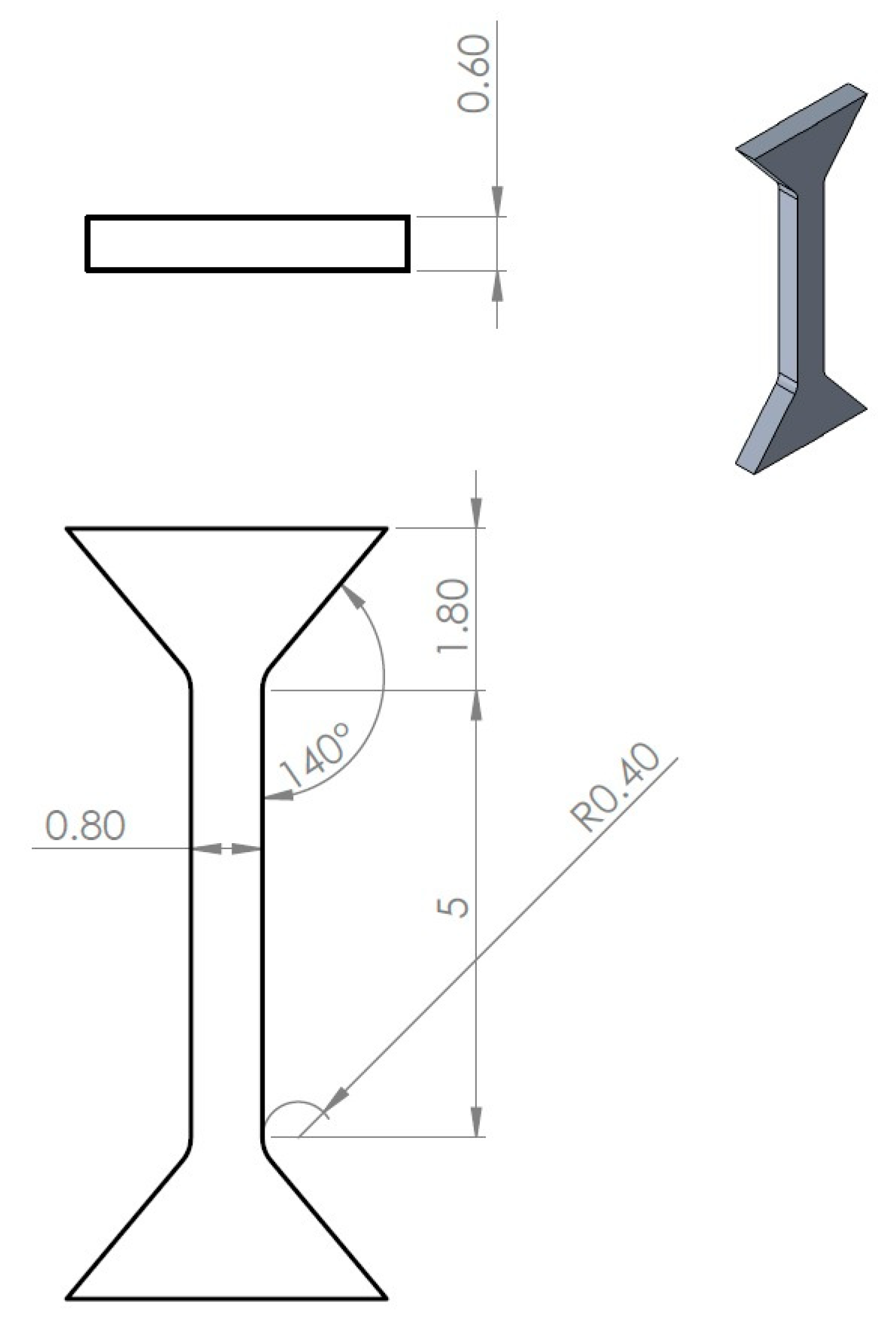
  • Small specimens for tensile test (SSTT), according to specifications in Figure 2;
  • Cubic specimens (5 × 5 × 3 mm) for microstructural analysis and hardness mapping.

2.4. Microstructural Characterization

Samples for microstructural analysis were mounted, ground using SiC papers (400, 800, and 1200 grit), and polished using diamond suspensions (3 and 1 μm). To reveal the microstructure, electrolytic etching was performed using a 10% perchloric acid solution in oxalic acid at 5 V with a current flow of 0.8–1.2 mA for 160 s.

2.5. Small Specimen Tensile Test (SSTT)

The miniature specimens were subjected to a tensile test on a Zwick/Roell Z005 (ZwickRoell GmbH & Co., Germany) testing machine equipped with a load cell range of ±5 kN. Non-contact optical strain analysis based on the DIC (Digital Image Correlation) method using Vic 2d software (Correlated Solutions Inc. Columbia, South Carolina, USA) was used to analyze the elongation of the miniature specimens during the tensile test. The initial absolute speed test for specimen sizes was 1 × 10⁻³ 1/s, which defined a crosshead travel speed of 0.01 mm/s. Due to material limitations, small and non-standardized samples were used in this study. Nonetheless, numerous previous works have performed control analysis on standardized samples.

3. Results

3.1. Impact of Parameters

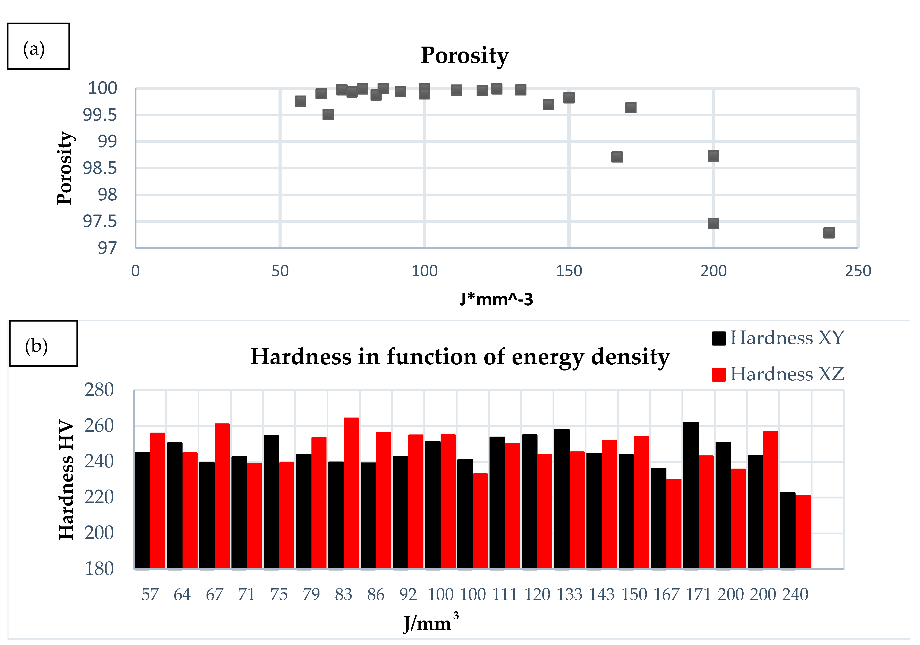
Porosity vs. Energy Density

Hardness measurements revealed values ranging from 223 to 262 HV across different parameter sets, as shown in Figure 3a,b. The average hardness for as-printed specimens using optimal parameters was 254 HV in the XY plane and 250 HV in the XZ plane, indicating slight anisotropy. The difference in hardness values between the XY and XZ planes (ΔHV) ranged from 2 to 25 units, with higher anisotropy generally observed at lower energy densities.
This anisotropy can be attributed to the directional solidification inherent to the LPBF process, resulting in columnar grain structures aligned with the build direction. Specimens printed with parameters yielding higher cooling rates (higher scan speeds, lower energy densities) typically exhibited greater anisotropy, likely due to more pronounced columnar grain formation.
The relationship between energy density and relative density (inversely related to porosity) was analyzed. Specimens printed with parameters yielding an energy density of 111 J/mm3 (900 mm/s scan speed, 120 W laser power) achieved the highest relative density of 99.96%. At energy densities below 100 J/mm3, lack-of-fusion defects dominated the microstructure, characterized by irregular, interconnected pores. Conversely, at energy densities exceeding 200 J/mm3, keyhole porosity increased, manifested as spherical voids from entrapped gases during excessive melting.
The energy density and porosity relationship did not follow a simple linear trend (Table 2), suggesting complex interactions between processing parameters. Parameters with similar energy densities but different combinations of power and speed sometimes yielded significantly different porosity levels, highlighting the limitations of using energy density as the sole optimization metric. However, it should be noted that the range 50–100 J/m3 seems the best in terms of density and hardness.
The analysis of the collected data reveals a clear correlation between the volumetric energy density (J) and the relative density and microhardness of the processed material. Optimal material properties are achieved within an energy density range of approximately 100 to 150 J/mm3. In this window, samples consistently exhibit high relative densities (above 99.9%) and balanced microhardness values across the XY and XZ planes, indicating uniform and stable microstructures. As energy density increases beyond this range (e.g., 200–240 J/mm3), a decline in relative density is observed, likely due to overheating, keyholing, or increased porosity. Conversely, too low of an energy input (<75 J/mm3) also results in lower densities and inconsistent hardness, suggesting insufficient melting. The hardness anisotropy (difference between the XY and XZ directions) generally increases with very high and very low energy inputs, highlighting the need for energy optimization to minimize directional property variation. Overall, samples processed at 900 mm/s with 120 W and a hatch distance width of 0.06 mm appear to offer the best balance between density and mechanical performance.

3.2. Microstructural Analysis

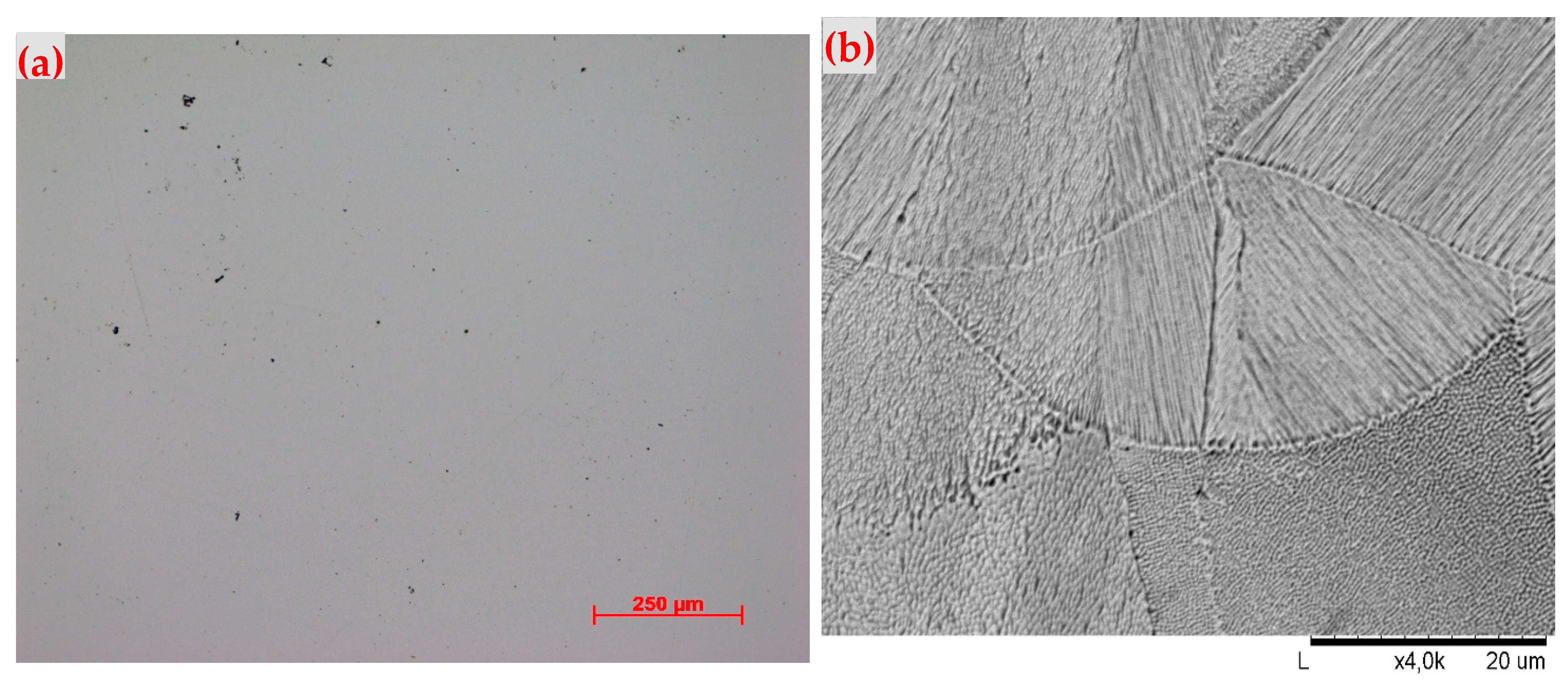
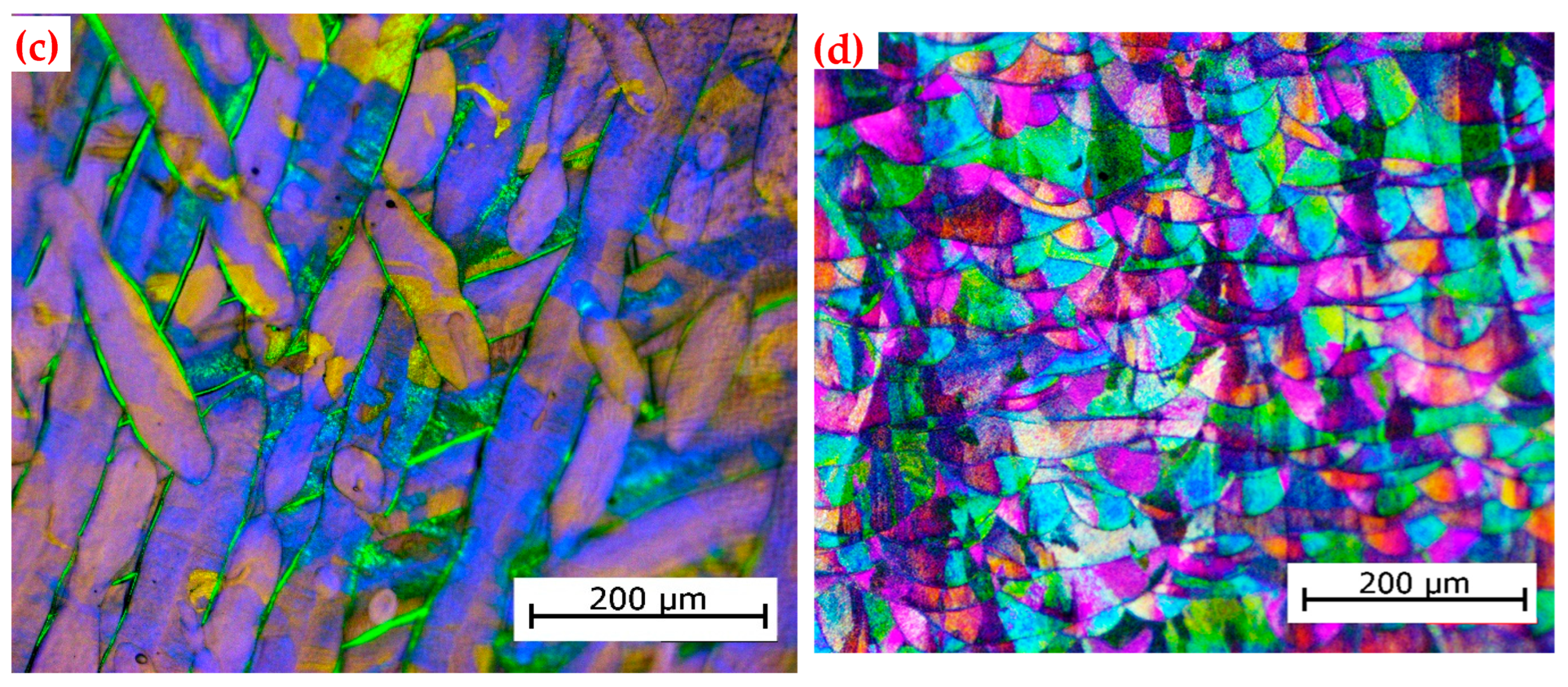
As-Printed Microstructure

Optical imaging of the as-printed specimens revealed a complex microstructure characterized by fine cellular/dendritic features within columnar grains (Figure 4). These cellular structures result from the rapid solidification conditions inherent to the LPBF process, with cell boundaries enriched in solute elements due to microsegregation during solidification.
In the XY plane (perpendicular to the build direction), the microstructure appeared as equiaxed sections of columnar grains, while the XZ plane revealed the elongated nature of these columnar grains. Polarized light microscopy highlighted the preferential grain growth direction along the build axis, with melt pool boundaries visible as arc-shaped features spanning multiple layers.

3.3. Mechanical Properties

Figure 5 shows the tensile curves for samples tested in the XY and XZ directions. The results within each group are very similar, which suggests that the material was uniform and the samples were representative. However, there are clear differences between the two directions. The XY samples showed higher strength but had lower elongation. In contrast, the XZ samples had higher elongation, but their strength was lower. This difference is likely caused by the differences in morphological texture. In the XZ direction, the material had a column-like grain structure that allowed dislocations to move more easily. This decreased significantly the strengthening effect in this particular orientation.
The tests were performed on the one selected sample that showed the most promising combination of relative density and hardness (Table 3).
In the case of specimens constructed in the XY direction, we can observe higher strength parameters in the form of proof stress, determined for a permanent deformation of 0.2% (R0.2 = 716 ± 5 MPa), as well as for ultimate tensile strength (Rm = 827 ± 7 MPa) compared to the XY direction (R0.2 = 613 ± 2 MPa and Rm = 651 ± 2 MPa). When analyzing the deformation capacity of the materials, we see an almost three times higher uniform deformation for the XZ direction compared to the XY direction (Ag = 42.8 ± 2.3% for XZ and Ag = 15.5 ± 0.6% for XY). This fact also translates directly into the total strain to rupture, which is higher for the material built in the XZ direction (A = 50.8 ± 2.6% for XZ and A = 19.2 ± 1.1% for XY). This high uniform strain for specimens built in the XZ direction is due to the relatively small strengthening process of the material during elongation in the uniform strain range—the slope of the tensile curves in the aforementioned strain range, for specimens built in the XZ direction, is much lower than for specimens representing the XY direction. Comparing the difference between the value of A and Ag, which defines the range of strain localization for us, we can conclude that it was approximately twice as large for specimens built in the XZ direction (8%) as for those built in the XY direction (3.7%).

4. Discussion

4.1. Processing Parameter Optimization and Energy Density Effects

The processing parameters employed for NickelAlloy HX demonstrate significant optimization compared to the literature values for nickel-based superalloys processed via LPBF (Table 4). The energy density of 111 J/mm3 falls within the optimal range identified by Marchese et al. [16] for nickel-based superalloys, avoiding excessive thermal input that can lead to keyhole formation, residual stress accumulation, and microstructural degradation. This moderate energy density approach contrasts with the higher values (>150 J/mm3) reported for Inconel 718 [17], which often result in increased thermal gradients and subsequent anisotropy.
The scan speed of 900 mm/s aligns with the recommendations of Esmaeilizadeh et al. [18], who demonstrated that higher scan speeds (>800 mm/s) reduce thermal accumulation while maintaining adequate overlap ratios. This parameter selection is particularly significant as it enables rapid processing while ensuring complete powder melting and minimal heat-affected zone formation. The laser power of 120 W represents a conservative approach compared to studies by Wang et al. [19], who utilized powers up to 285 W for Inconel 718, which often resulted in increased spatter formation and surface roughness.
Table 4. Processing parameters comparison for LPBF nickel-based superalloys.
MaterialReferenceLaser Power (W)Scan Speed (mm/s)Layer Thickness (μm)Energy Density (J/mm3)Relative Density (%)
EOS NickelAlloy HXThis study1209003011199.8
Hastelloy X[17]19512003010399.2
Hastelloy X[18]1808004011798.8
Hastelloy X[20]15010003012599.1
Inconel 718[19]2859604017599.4
Inconel 718[21]19512002512999.6
Inconel 625[16]1956503016799.3
CM247LC[22]2004003039798.5
The high relative density achieved with NickelAlloy HX (99.8%) demonstrates the effectiveness of the optimized parameter set, exceeding values reported for most nickel-based superalloys in the literature.
Powder characteristics critically influence LPBF processing of nickel-based superalloys like EOS NickelAlloy HX in aerospace applications. Spherical powder morphology with a particle size distribution of 15–45 μm ensures optimal flowability and packing density, directly affecting layer uniformity and required laser energy density parameters [15]. Poor powder flowability necessitates reduced scanning speeds and increased laser power to achieve full densification, while irregular particle shapes promote gas entrapment, leading to increased porosity levels exceeding 1% [23]. Powder recycling in LPBF processes increases oxygen content and satellite particle formation, resulting in oxide inclusions that act as crack-initiation sites, reducing tensile strength by up to 10% and significantly degrading fatigue performance in Hastelloy components [24]. The connection between powder quality and LPBF parameters is essential for achieving porosity levels below the 0.2% required for aerospace applications, where minor defects can reduce significantly the elongation and induce brittleness in the material.

4.2. Microstructural Evolution and Grain Morphology

Mechanical Properties Enhancement and Performance Analysis

The mechanical properties of NickelAlloy HX demonstrate good performance compared to LPBF-processed EOS NickelAlloy HX (Table 5) variants documented by Sanchez et al. [24]. The yield strength of 716 MPa represents a 49% improvement over conventional LPBF Hastelloy X (480 MPa) reported by Han et al. [18], while maintaining superior ductility compared to higher-strength variants. This value is particularly significant as it addresses the traditional strength–ductility trade-off commonly observed in LPBF materials.
The tensile strength of 827 MPa positions EOS NickelAlloy HX between the moderate-strength, high-ductility Hastelloy X variants and the higher-strength Inconel 718 alloys, providing an optimal balance for aerospace applications. The elongation of 19.2% substantially exceeds the typical 12–15% reported for high-strength LPBF nickel alloys [25], indicating good microstructural refinement and defect control.

4.3. Microstructural Analysis and Grain Structure Effects

The microstructural characteristics of NickelAlloy HX align with findings reported by Popovich et al. [26] for optimally processed nickel superalloys. The fine grain structure observed contributes significantly to the enhanced mechanical properties through Hall–Petch strengthening mechanisms. Compared to the coarse columnar grains typically reported for Hastelloy X [17], the refined microstructure of EOS NickelAlloy HX demonstrates effective thermal management during processing.
The absence of significant constitutional liquation and Laves phase formation, commonly reported for Inconel 718 [27], indicates superior compositional control and thermal history optimization. This microstructural stability is crucial for maintaining consistent properties across different build orientations and component geometries.

4.4. Quality Assessment and Defect Analysis Comparison

The defect analysis for NickelAlloy HX correlates directly with the mechanical properties (Table 6). The relative density of 99.8% was achieved by decreasing the pore sizes and defect density, which were particularly visible in the mechanical analysis and high elongation values. Wang et al. [28] demonstrated that porosity levels below 0.5% are critical for achieving optimal strength–ductility combinations in LPBF nickel alloys, a threshold clearly exceeded in this study.
The present study demonstrates that, although volumetric energy density (E) provides a useful first-order guideline for LPBF parameter selection, the complex interplay between laser power (P), scan speed (v), and hatch spacing (h) must be considered to fully understand porosity formation, microstructure evolution, and mechanical anisotropy in EOS NickelAlloy HX. Our finding that an energy density of ≈111 J·mm−3 (P = 120 W, v = 900 mm·s−1, h = 0.06 mm) yields the highest relative density (99.96%) and balanced hardness highlights the benefits of operating in the conduction-mode melting regime, where stable melt pools minimize keyhole porosity and ensure good interlayer bonding (King et al. [9]; Cunningham et al. [10]).
However, equating different P–v–h combinations to the same E can be misleading. For example, specimens processed at 100 W/800 mm·s−1/0.07 mm (E = 179 J·mm−3) showed significantly lower density (98.7%) than those at 120 W/900 mm·s−1/0.06 mm, despite similar E values. We attribute this to the transition from conduction- to keyhole-dominated melting at high E, which leads to unstable vapor cavities that collapse into spherical porosity (Zhang et al. [8]; Wang et al. [28]). Conversely, at low E (<75 J·mm−3), insufficient melt-pool overlap and depth result in lack-of-fusion defects characterized by irregular, interconnected pores (DebRoy et al. [2]; Zhang et al. [8]).
Microstructural examination revealed a fine cellular–dendritic substructure (0.5–1.5 µm spacing) within columnar grains, consistent with rapid solidification rates (105–106 K·s−1). The columnar-to-equiaxed grain morphology change between the XZ and XY planes underlies the pronounced tensile anisotropy: higher UTS in XY (827 MPa) versus greater ductility in XZ (A = 50.8%). Similar behavior has been reported for LPBF Inconel 718 and Hastelloy X, where directional solidification aligns grains along the thermal gradient, promoting anisotropic mechanical response (Popovich et al. [21]; Keshavarzkermani et al. [20]). Post-build heat treatments (solutionizing plus aging or hot isostatic pressing) could promote recrystallization and homogenization of solute segregation, thereby reducing both microstructural anisotropy and residual porosity (Park et al. [29]).
Compared to conventionally cast or wrought HX (σYS = 350–400 MPa; A ≈ 35% [6,7]), LPBF-processed HX exhibits approximately double the yield strength and superior ductility along the build direction. This strength enhancement primarily arises from Hall–Petch strengthening due to the refined cellular–dendritic structure and solution hardening by Mo and Cr enrichment at the cell boundaries. The absence of deleterious Laves phases and constitutional liquation—often encountered in LPBF Inconel 718—suggests that the HX composition and thermal history here are inherently more resistant to microsegregation-induced embrittlement (Murr et al. [3]; Popovich et al. [21]).

5. Conclusions

The main findings of the research were as follows:
  • Effect of LPBF Process Parameters on Material Density and Microstructure
    The proper selection of LPBF processing parameters, particularly a volumetric energy density of 111 J/mm3 (P = 200 W, v = 900 mm/s, hatch spacing = 0.1 mm, layer thickness = 0.02 mm), enabled the production of samples with very high density—up to 99.96%. Higher scanning speeds (≥900 mm/s), when combined with proportionally increased laser power, led to improved material quality compared to low-speed strategies. Regardless of the applied parameters, all samples exhibited a fine cellular–dendritic microstructure (0.5–1.5 µm) within the columnar grains, resulting from extremely high cooling rates (105–106 K/s). Moreover, a clear transition from columnar to equiaxed grains was observed depending on the sample orientation (XZ vs. XY), which had a direct impact on the mechanical properties of the material.
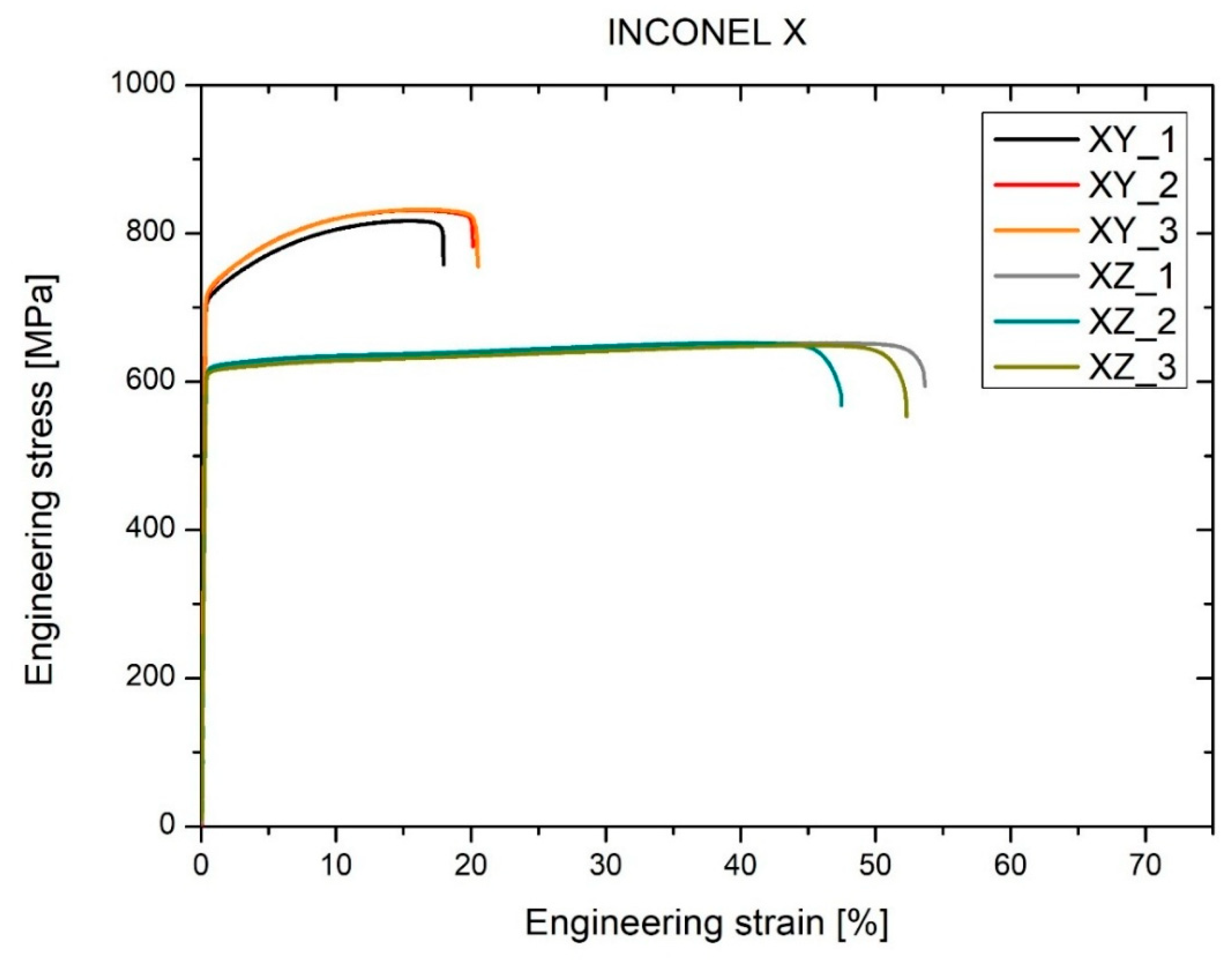
  • Anisotropy of Mechanical Properties
    The fabricated samples showed a distinct anisotropy of mechanical properties depending on the build orientation. In the XY orientation, a higher ultimate tensile strength was recorded (UTS= 827 ± 7 MPa), but with lower elongation (A = 19.2 ± 1.1%), whereas in the XZ orientation, lower strength (UTS = 651 ± 2 MPa) was accompanied by significantly higher ductility (A = 50.8 ± 2.6%). These differences clearly confirm the substantial influence of build direction in LPBF technology on the strength characteristics of the alloy.
  • Comparison with Conventionally Processed Material
    The mechanical properties of samples produced via LPBF (yield strength in the range of 580–698 MPa) significantly exceed those of conventionally cast or rolled Nickel Alloy HX (YS = 350–400 MPa, A ≈ 35%). This advantage results from the fine-grained microstructure and the ability to precisely control process parameters, allowing for optimized tailoring of the material’s properties.

Author Contributions

Conceptualization, R.S., K.J. and P.M.; methodology, R.S., K.J., R.M. and P.M.; software, P.M.; validation, R.S. and P.M.; formal analysis, R.S., K.J., J.M. and P.M.; investigation, K.J., R.S., R.M. and P.M.; resources, P.M.; data curation, P.M.; writing—original draft preparation, K.J., R.S., R.M. and P.M.; writing—review and editing, K.J., R.S., P.M. and J.M.; visualization, K.J., R.S., P.M. and J.M.; supervision, R.S. and P.M.; project administration, R.S.; funding acquisition, R.S. All authors have read and agreed to the published version of the manuscript.

Funding

The scientific research was financed from the statutory work Ref. No. 504/04812/1090/44.000000.

Institutional Review Board Statement

Not applicable.

Informed Consent Statement

Not applicable.

Data Availability Statement

Data are contained within the article.

Acknowledgments

This study was financed by the Warsaw University of Technology, Faculty of Materials Science and Engineering, from the statutory work 504/04812/1090/44.000000.

Conflicts of Interest

The authors declare no conflicts of interest.

References

  1. Frazier, W.E. Metal additive manufacturing: A review. J. Mater. Eng. Perform. 2014, 23, 1917–1928. [Google Scholar] [CrossRef]
  2. DebRoy, T.; Wei, H.L.; Zuback, J.S.; Mukherjee, T.; Elmer, J.W.; Milewski, J.O.; Beese, A.M.; Wilson-Heid, A.; De, A.; Zhang, W. Additive manufacturing of metallic components–Process, structure and properties. Prog. Mater. Sci. 2018, 92, 112–224. [Google Scholar] [CrossRef]
  3. Murr, L.E.; Gaytan, S.M.; Ramirez, D.A.; Martinez, E.; Hernandez, J.; Amato, K.N.; Shindo, P.W.; Medina, F.R.; Wicker, R.B. Metal fabrication by additive manufacturing using laser and electron beam melting technologies. J. Mater. Sci. Technol. 2012, 28, 1–14. [Google Scholar] [CrossRef]
  4. Gibson, I.; Rosen, D.W.; Stucker, B.; Khorasani, M. Additive Manufacturing Technologies, 3rd ed.; Springer: Cham, Switzerland, 2021. [Google Scholar]
  5. Yap, C.Y.; Chua, C.K.; Dong, Z.L.; Liu, Z.H.; Zhang, D.Q.; Loh, L.E.; Sing, S.L. Review of selective laser melting: Materials and applications. Appl. Phys. Rev. 2015, 2, 041101. [Google Scholar] [CrossRef]
  6. Reed, R.C. The Superalloys: Fundamentals and Applications; Cambridge University Press: Cambridge, UK, 2006. [Google Scholar]
  7. Pollock, T.M.; Tin, S. Nickel-based superalloys for advanced turbine engines: Chemistry, microstructure and properties. J. Propuls. Power 2006, 22, 361–374. [Google Scholar] [CrossRef]
  8. Zhang, B.; Li, Y.; Bai, Q. Defect formation mechanisms in selective laser melting: A review. Chin. J. Mech. Eng. 2017, 30, 515–527. [Google Scholar] [CrossRef]
  9. King, W.E.; Barth, H.D.; Castillo, V.M.; Gallegos, G.F.; Gibbs, J.W.; Hahn, D.E.; Kamath, C.; Rubenchik, A.M. Observation of keyhole-mode laser melting in laser powder-bed fusion additive manufacturing. J. Mater. Process. Technol. 2014, 214, 2915–2925. [Google Scholar] [CrossRef]
  10. Cunningham, R.; Zhao, C.; Parab, N.; Kantzos, C.; Pauza, J.; Fezzaa, K.; Sun, T.; Rollett, A.D. Keyhole threshold and morphology in laser melting revealed by ultrahigh-speed x-ray imaging. Science 2019, 363, 849–852. [Google Scholar] [CrossRef] [PubMed]
  11. Thijs, L.; Verhaeghe, F.; Craeghs, T.; Van Humbeeck, J.; Kruth, J.P. A study of the microstructural evolution during selective laser melting of Ti–6Al–4V. Acta Mater. 2010, 58, 3303–3312. [Google Scholar] [CrossRef]
  12. AlMangour, B.; Grzesiak, D.; Yang, J.M. Rapid fabrication of bulk-form TiB2/316L stainless steel nanocomposites with novel reinforcement architecture and improved performance by selective laser melting. J. Alloys Compd. 2016, 680, 480–493. [Google Scholar] [CrossRef]
  13. Sames, W.J.; List, F.A.; Pannala, S.; Dehoff, R.R.; Babu, S.S. The metallurgy and processing science of metal additive manufacturing. Int. Mater. Rev. 2016, 61, 315–360. [Google Scholar] [CrossRef]
  14. Gu, D.D.; Meiners, W.; Wissenbach, K.; Poprawe, R. Laser additive manufacturing of metallic components: Materials, processes and mechanisms. Int. Mater. Rev. 2012, 57, 133–164. [Google Scholar] [CrossRef]
  15. Marchese, G.; Garmendia Colera, X.; Calignano, F.; Lorusso, M.; Biamino, S.; Minetola, P.; Manfredi, D. Characterization and comparison of Inconel 625 processed by selective laser melting and laser metal deposition. Adv. Eng. Mater. 2017, 19, 1600635. [Google Scholar] [CrossRef]
  16. Marchese, G.; Lorusso, M.; Parizia, S.; Bassini, E.; Lee, J.-W.; Calignano, F.; Manfredi, D.; Terner, M.; Hong, H.-U.; Ugues, D.; et al. Influence of heat treatments on microstructure evolution and mechanical properties of Inconel 625 processed by laser powder bed fusion. Mater. Sci. Eng. A 2018, 729, 64–75. [Google Scholar] [CrossRef]
  17. Tomus, D.; Rometsch, P.A.; Heilmaier, M.; Wu, X. Effect of minor alloying elements on the mechanical properties of Hastelloy X fabricated by selective laser melting. Addit. Manuf. 2017, 16, 65–72. [Google Scholar]
  18. Esmaeilizadeh, R.; Keshavarzkermani, A.; Ali, U.; Mahmoodkhani, Y.; Behravesh, B.; Jahed, H.; Bonakdar, A.; Toyserkani, E. Customizing Mechanical Properties of Additively Manufactured Hastelloy X Parts by Adjusting Laser Scanning Speed. J. Alloys Compd. 2020, 812, 152097. [Google Scholar] [CrossRef]
  19. Wang, Z.; Guan, K.; Gao, M.; Li, X.; Chen, X.; Zeng, X. The microstructure and mechanical properties of deposited-IN718 by selective laser melting. J. Alloys Compd. 2012, 513, 518–523. [Google Scholar] [CrossRef]
  20. Keshavarzkermani, A.; Esmaeilizadeh, R.; Ali, U.; Enrique, P.D.; Mahmoodkhani, Y.; Zhou, N.Y.; Bonakdar, A.; Toyserkani, E. Controlling mechanical properties of additively manufactured hastelloy X by altering solidification pattern during laser powder-bed fusion. Mater. Sci. Eng. A 2019, 762, 138081. [Google Scholar] [CrossRef]
  21. Popovich, V.; Borisov, E.; Popovich, A.; Sufiiarov, V.; Masaylo, D.; Alzina, L. Impact of heat treatment on mechanical behaviour of Inconel 718 processed with tailored microstructure by selective laser melting. Mater. Des. 2017, 131, 12–22. [Google Scholar] [CrossRef]
  22. Munoz-Moreno, R.; Divya, V.; Driver, S.; Messé, O.; Illston, T.; Baker, S.; Carpenter, M.; Stone, H. Effect of heat treatment on the microstructure, texture and elastic anisotropy of the nickel-based superalloy CM247LC processed by selective laser melting. Mater. Sci. Eng. A 2016, 674, 529–539. [Google Scholar] [CrossRef]
  23. Tang, M.; Pistorius, P.C.; Beuth, J.L. Prediction of lack-of-fusion porosity for powder bed fusion. Addit. Manuf. 2017, 14, 39–48. [Google Scholar] [CrossRef]
  24. Sanchez, S.; Smith, P.; Xu, Z.; Gaspard, G.; Hyde, C.J.; Wits, W.W.; Ashcroft, I.A.; Chen, H.; Clare, A.T. Powder Bed Fusion of nickel-based superalloys: A review. Int. J. Mach. Tools Manuf. 2021, 165, 103729. [Google Scholar] [CrossRef]
  25. Gribbin, S.; Bicknell, J.; Jorgensen, L.; Tsukrov, I.; Knezevic, M. Low cycle fatigue behavior of direct metal laser sintered Inconel alloy 718. Int. J. Fatigue 2016, 93, 156–167. [Google Scholar] [CrossRef]
  26. Popovich, V.A.; Borisov, E.V.; Popovich, A.A.; Sufiiarov, V.S.; Masaylo, D.V.; Alzina, L. Functionally graded Inconel 718 processed by additive manufacturing: Crystallographic texture, anisotropy of microstructure and mechanical properties. Mater. Des. 2017, 114, 441–449. [Google Scholar] [CrossRef]
  27. Amato, K.N.; Gaytan, S.M.; Murr, L.E.; Martinez, E.; Shindo, P.; Hernandez, J.; Collins, S.; Medina, F. Microstructures and mechanical behavior of Inconel 718 fabricated by selective laser melting. Acta Mater. 2012, 60, 2229–2239. [Google Scholar] [CrossRef]
  28. Wang, P. Defect formation mechanisms in powder bed fusion additive manufacturing: A review. Chin. J. Mech. Eng. 2020, 33, 15. [Google Scholar]
  29. Park, J.; Lee, J.; Kim, K.; Kim, D. Effect of post-processing heat treatment on microstructure and mechanical properties of additively manufactured Inconel 718. Mater. Sci. Eng. A 2021, 815, 141248. [Google Scholar]
Figure 1. Powder analysis results: (a) particle size distribution (PSD) and scanning electron microscopy (SEM) images at (b) ×2000 and (c) ×500 magnifications.
Applsci 15 08011 g001
Figure 2. Dimensions of small specimens used in tensile tests (Dimension in mm).
Applsci 15 08011 g002
Figure 3. Porosity (a) and hardness in the XY plane (b) and XZ plane as a function of the power of the laser.
Applsci 15 08011 g003
Figure 4. Microstructure of NickelAlloy HX sample printed with 111 energy density, (a) XZ microstructure after polishing, (b) XZ view microstructure after chemical etching observed under SEM microstructure, (c) XY microstructure microstructure after chemical etching observed in polarized light under LM, (d) XZ observation of microstructure after chemical etching viewed under LM.
Applsci 15 08011 g004aApplsci 15 08011 g004b
Figure 5. Mechanical properties of the HX alloy in two main directions.
Applsci 15 08011 g005
Table 1. Nominal chemical composition of EOS NickelAlloy HX powder (wt%).
Ni Cr Fe Mo Mg Si W Co Al Ti
Rest20.5–2317–208–100.2–11 max0.2–10.5–2.50.5 max0.15 max
Table 2. The optimization data for the HX alloy. All samples were manufactured with preheating and building layer height of 0.02 mm. Red row is the best parameters.
ProcessParametersPowerHatch
Distance
Layer HeightEnergy
Density
Density [%]Hardnes
V [mm/s]P [W]d [mm]h [mm]J [J·mm-3]d = 0.06XYXZDifference XYXZ
Preheating1000400.040.0250
11000800.070.025799.7624525611
21000900.070.026499.902502456
31000800.060.026799.5123926122
410001000.070.027199.972432394
51000900.060.027599.9325523915
610001100.070.027999.9924425410
710001000.060.028399.8724026425
810001200.070.028699.9923925617
910001100.060.029299.9424325512
1010001200.060.0210099.992512554
1110001200.060.0210099.902412338
129001200.060.0211199.962542504
1310001200.050.0212099.9625524411
148001200.060.0212599.99248244
159001200.050.0213399.9725824513
167001200.060.0214399.692442527
178001200.050.0215099.8224425411
186001200.060.0216798.712362306
197001200.050.0217199.6326224319
205001200.060.0220097.4625123615
216001200.050.0220098.7324325714
225001200.050.0224097.292232212
Table 3. Mechanical properties of HX alloy for the two main directions.
DirectionSpecimenProof Stress at 0.2%
R0.2 [MPa}
Ultimate Tensile Stress
Rm [MPA]
Uniform Strain
Ag [%]
Strain to Rapture
A [%]
XYXY_170981714.817.6
XY_271883115.219.8
XY_372283216.320.2
average71682715.519.2
std. deviation570.61.1
XZXZ_161365244.853.3
XZ_261665239.547.2
XZ_361164944.152.0
average61365142.850.8
std. deviation222.32.6
Table 5. Mechanical properties comparison of LPBF nickel-based superalloys (as-built condition).
MaterialReferenceBuild OrientationYield Strength (MPa)Tensile Strength (MPa)Elongation (%)
EOS NickelAlloy HXThis studyXY716 ± 5827 ± 719.2 ± 1.1
Hastelloy X[18]Z480 ± 10620 ± 1540.0 ± 2.0
Hastelloy X[17]Z792 ± 1923 ± 912.0 ± 0.5
Hastelloy X[18]XY663 ± 12773 ± 922.4 ± 1.5
Inconel 718[19]Z559 ± 15782 ± 1831.0 ± 2.1
Inconel 718[21]XY1211 ± 241406 ± 2113.6 ± 4
Inconel 625[16]XY559 ± 20894 ± 2530.0 ± 3.2
CM247LC[22]Z690 ± 25791 ± 181.15 ± 0.2
Table 6. Quality metrics and defect analysis comparison.
MaterialReferenceRelative Density (%)Primary Defect TypePorosity Size (μm)Defect Density (Defects/mm2)Microhardness (HV)
NickelAlloy HXThis study99.8Minimal spherical<10<5285 ± 8
Hastelloy X[17]99.2Lack of fusion15–5015–25265 ± 12
Hastelloy X[18]98.8Gas porosity5–2520–35248 ± 15
Inconel 718[19]99.4Spherical pores10–408–15310 ± 18
Inconel 718[21]99.6Minimal defects<15<8295 ± 22
Inconel 625[16]99.3Gas porosity8–3012–20245 ± 14
CM247LC[22]98.5Microcracks20–8050–120420 ± 35
Disclaimer/Publisher’s Note: The statements, opinions and data contained in all publications are solely those of the individual author(s) and contributor(s) and not of MDPI and/or the editor(s). MDPI and/or the editor(s) disclaim responsibility for any injury to people or property resulting from any ideas, methods, instructions or products referred to in the content.

