Article

Adaptive Control of the Aerodynamic Flaps of the Savonius Rotor Under Variable Wind Loads

1
Department of Electronic Engineering, Almaty University of Power Engineering and Telecommunications named after G. Daukeev, Almaty 05000, Kazakhstan
2
Department of Telecommunications, University of Ruse, 8 Studentska Str., 7004 Ruse, Bulgaria
*
Authors to whom correspondence should be addressed.
Appl. Sci. 2025, 15(11), 6096; https://doi.org/10.3390/app15116096
Submission received: 16 April 2025 / Revised: 26 May 2025 / Accepted: 27 May 2025 / Published: 28 May 2025

Abstract

:
This study presents the development of an adaptive control system for aerodynamic flaps of a two-tier vertical-axis Savonius wind rotor to improve performance under variable wind loads. The approach includes detailed kinematic and dynamic modeling of the flap actuation mechanism, accounting for real-world nonlinearities such as backlash, friction, and impact loads. The mechanical transmission system is analyzed to evaluate the influence of design parameters on system dynamics and control accuracy. A mathematical model of an adaptive PID controller is proposed, capable of real-time adjustment of gain parameters based on external wind torque. Numerical simulations under various wind conditions demonstrate that adaptive tuning significantly enhances system stability, reduces overshoot, and ensures faster response compared to fixed-parameter controllers. Sensitivity analysis confirms the importance of mass distribution, mechanical stiffness, and damping in minimizing vibrations and ensuring durability. The developed system provides a reliable solution for efficient wind energy conversion in dynamic environments, including urban and coastal applications.

1. Introduction

Vertical-axis wind turbines (VAWTs) with Savonius rotors have gained increasing scientific attention in recent years due to their structural simplicity, low noise levels, ability to operate under weak and variable wind flows, and resilience to abrupt wind load changes. These turbines offer several advantages over their horizontal-axis counterparts, including omnidirectional wind capture, efficient operation at low wind speeds, no need for wind-direction alignment, and reduced operating costs. This makes them especially attractive for urban environments and remote areas [1].
Despite these advantages, Savonius-type VAWTs are characterized by relatively low wind energy conversion efficiency. A key research direction for improving their performance lies in the implementation of adaptive aerodynamic elements, such as controllable flaps. These components allow for real-time adjustment of aerodynamic drag and lift forces on the blades, thereby significantly improving the generator’s performance across a wide range of wind conditions.
Aerodynamic flaps mounted on Savonius rotor blades can optimize airflow around the blades and effectively control the torque generated by the wind [2]. This, in turn, helps to minimize mechanical stress on structural components, extending their service life and reducing maintenance costs. However, effective utilization of such flaps requires a sophisticated control system capable of rapidly and accurately responding to constantly changing external conditions, including sudden gusts and abrupt variations in wind direction and speed.
Most existing flap control approaches rely on traditional controllers with fixed parameters, which demonstrate limited adaptability and insufficient responsiveness under real-world operational conditions [3]. These systems often fail to adequately compensate for dynamic disturbances and abrupt wind fluctuations, leading to decreased overall turbine performance and increased risk of mechanical damage.
Research aimed at improving the efficiency of vertical-axis wind turbines (VAWTs) of the Savonius type has been actively evolving over the past decade, offering various approaches and methodologies. However, many existing studies exhibit certain limitations that must be taken into account. In [4], researchers developed an adaptive control system for Savonius rotor blades with automatic adjustment of the angle of attack to optimize performance in urban environments. Although the proposed method demonstrated improved overall system efficiency, the study did not consider critical nonlinear effects such as backlash and friction, which can negatively impact the positioning accuracy of aerodynamic elements under real operating conditions. In [5], researchers proposed an automatic control system for the aerodynamic flaps of a Savonius rotor to enhance energy efficiency. However, their analysis was limited to gradual changes in wind load, without examining the impact of sudden gusts and dynamic disturbances, which restricts the practical applicability of their solution under variable weather conditions. In [6], researchers investigated active control of aerodynamic elements in vertical-axis wind turbines to reduce mechanical stress and extend structural lifespan. However, their work lacked adaptive adjustment of control actions under dynamically changing wind conditions, which may reduce the system’s overall stability and reliability. In [7], an adaptive PID control strategy was implemented, focusing on modifying regulator coefficients based on wind speed. While this research demonstrated favorable transient characteristics, it did not address issues related to mechanical clearances and impact loads, which can cause instability and wear of control components. In [8,9], researchers focused on dynamic modeling and analysis of mechanical loads in vertical-axis wind turbines. These works provide valuable data on structural response to external loads; however, they do not incorporate control algorithms that account for real mechanical nonlinearities such as backlash and viscous friction. In [10], researchers proposed a backlash compensation algorithm for control mechanisms in vertical-axis wind turbines. Nevertheless, the study did not include adaptive tuning of control parameters under sudden changes in wind load, which may reduce the system’s stability in real-world conditions. In [11], researchers examined the impact of friction on the quality of blade control in wind turbines. Although the authors provided a detailed analysis of the negative effects of friction, they did not offer adequate methods for compensating for this effect under dynamically changing loads. In [12,13,14], researchers focused on optimizing PID controllers for VAWT control. These studies present interesting approaches to regulator coefficient selection, but the proposed solutions were not tested for robustness under sustained and abrupt wind loads, leaving questions about the reliability and effectiveness of the methods unresolved.
Predictive approaches described in [15,16] and Ref. [17] offer promising techniques for wind turbine control, particularly under variable wind conditions. However, these studies primarily focus on controller tuning and wind adaptation, without explicitly modeling the mechanical nonlinearities present in actuator-flap systems. Key effects such as backlash, dry friction, and impulsive torque disturbances are either neglected or highly simplified, which limits the applicability of the proposed methods in real mechanical configurations.
In contrast, Ref. [18] provides a detailed kinematic and dynamic analysis of vertical-axis wind turbine (VAWT) structures, addressing the physical behavior of the system components. Yet, it lacks the integration of adaptive or predictive control methods, which are essential for enhancing system responsiveness and energy efficiency.
The present work combines both perspectives by introducing an adaptive control strategy grounded in a high-fidelity dynamic model that incorporates mechanical nonlinearities. This integration ensures that the control algorithm remains robust under real-world conditions, where actuator imperfections and structural dynamics significantly affect system performance. This combined modeling-and-control approach constitutes the main novelty of the proposed study.
This study addresses these challenges through a comprehensive approach that includes detailed kinematic and dynamic modeling of the aerodynamic flap control system for a two-tier Savonius rotor. Special attention is given to the integration of mechanical components, actuators (in particular, servos), and the development of mathematical models that fully consider nonlinear factors such as backlash, friction, and dynamic loads. A key aspect of this research is the optimization of adaptive PID controller parameters and the integration of predictive control elements to ensure high efficiency and reliability of the system under real operating conditions.

2. Materials and Methods

The Savonius wind turbine considered in this study is a vertical-axis machine with a rotor composed of two tiers, each featuring three blades. Each blade is equipped with a semicircular aerodynamic flap designed to control airflow based on the current wind speed.
Each flap is made of 0.5 mm thick sheet metal, shaped as a semicircle with a 25 cm arc length and 30 cm height. The flap rotates around its own axis, and the angle of rotation determines the extent to which it obstructs the airflow and, consequently, influences the torque generated by the corresponding blade.
Flap actuation is performed using an MG996R servo motor manufactured by Tower Pro, based in Taichung City, Taiwan. The motor is located at the rotor base, near the central axis. Mechanical transmission to the flap is accomplished through a lever mechanism that includes [19] the following:
  • The servo motor’s output shaft;
  • A steel rod lever (6 mm in diameter);
  • A connecting joint (axle) linking the lever to the flap and enabling its rotational movement.
The servo motors are automatically controlled based on signals from a controller that monitors the current wind speed. When a defined threshold (25 m/s) [20] is exceeded, the forced flap-closing mechanism is activated to reduce rotor load and prevent mechanical damage.
Every component of the mechanism must be incorporated into the system’s kinematic and dynamic models, as the interaction between the links affects the system’s response to control actions and external disturbances.
The kinematic scheme of the aerodynamic flap control mechanism is a closed system of lever and rotational links, ensuring the transmission of control motion from the servo to the flap. It is designed for analyzing displacements, velocities, and accelerations of all links under predefined input motion laws (i.e., rotation angle of the servo motor’s output shaft).
The system consists of the following main kinematic links:
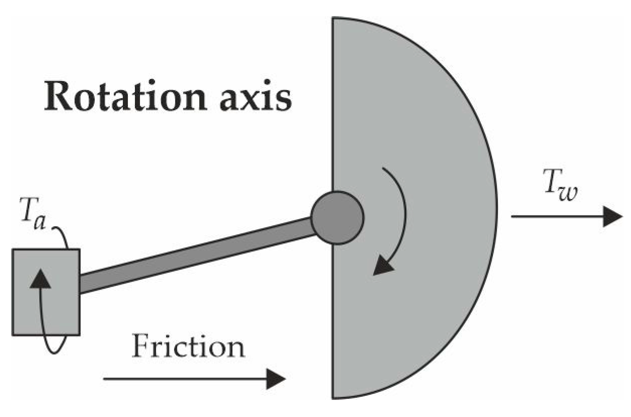
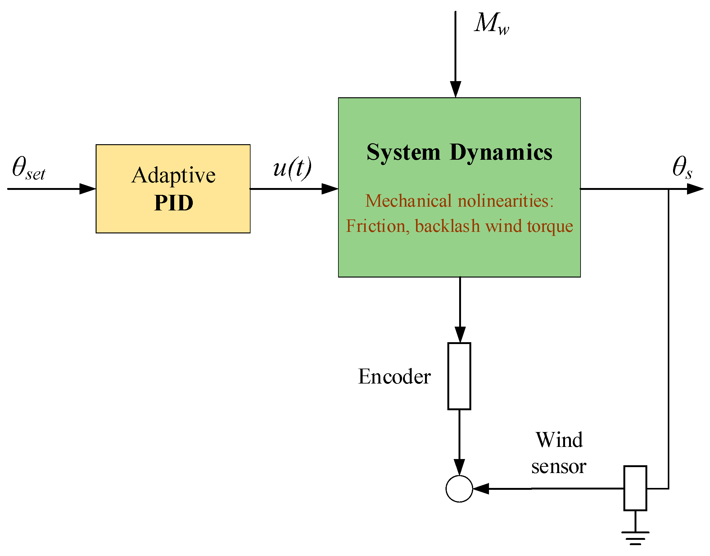
  • Servo motor (Link 1)—provides rotational motion. A shaft rigidly connected to the lever is mounted on the motor’s output. The rotation angle is denoted as θm(t).
  • Gearbox (Link 2)—built into the servo housing, it reduces speed and increases output torque. Its gear ratio is denoted as ir, and the output angle as θr(t).
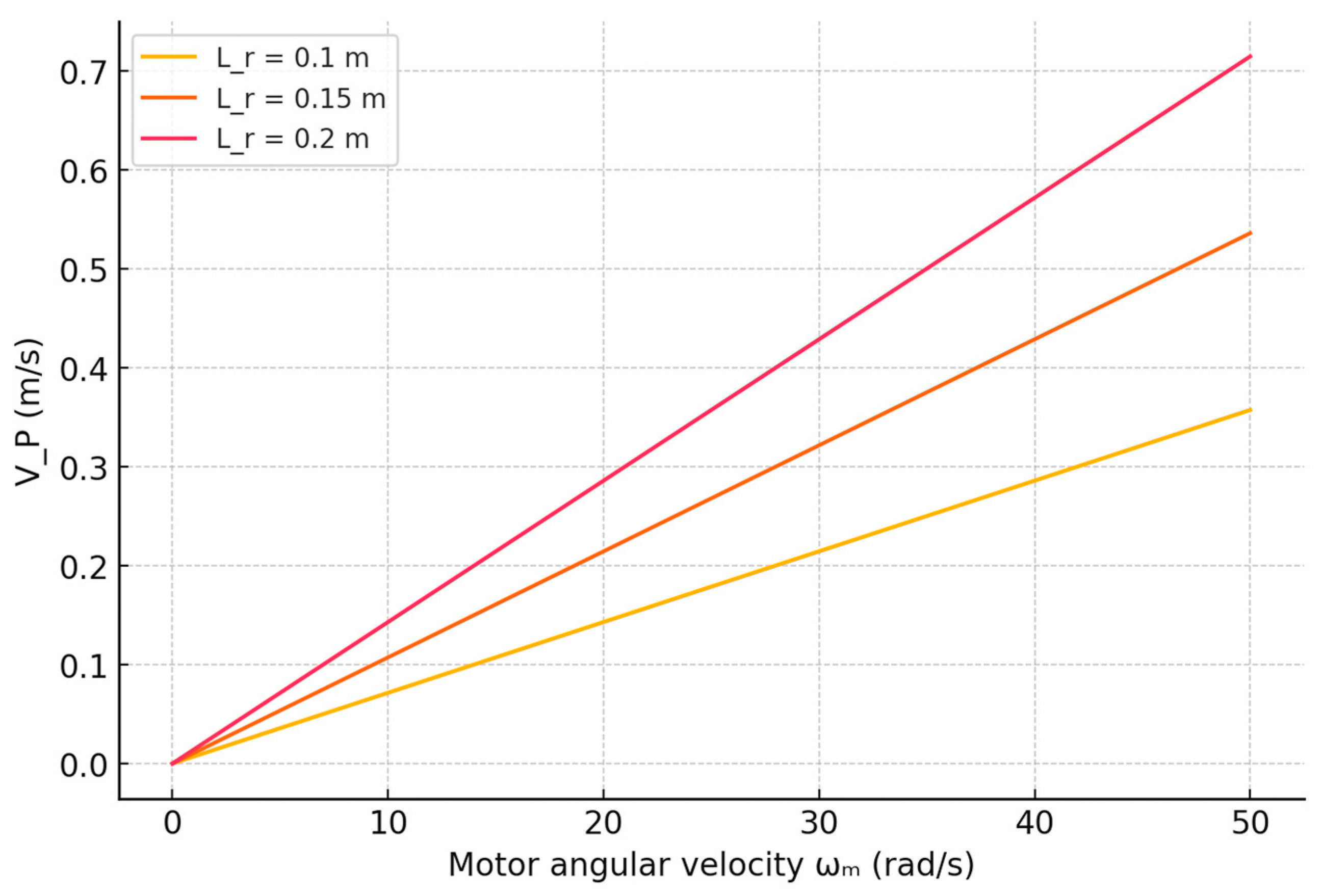
  • Lever (Link 3)—a straight link of length Lr, rotating around the gearbox axis. It moves the flap connection point along an arc of a certain radius.
  • Connecting joint and flap (Link 4)—the flap receives rotation from the lever. The flap rotation is denoted by the angle θs(t), which is linked to the input angle via the complete kinematic transmission (Figure 1).
Let O be the center of the drive shaft, and P be the end of the lever. Then the coordinates of point P over time are expressed as [21]
x P t = L r cos θ r t and   y P t = L r sin θ r t
where θ r t = θ m t i r is angle of lever rotation.
The diagram shows the mechanical linkage between the servo motor and the aerodynamic flap. Point O represents the center of the motor shaft, which generates the input angular motion θm(t). A rigid lever of length Lr is attached to the shaft and rotates around point O. The end of the lever is denoted as point P, which follows a circular trajectory around O.
Point A is located on the outer edge of the semicircular flap, at a distance Rs from its axis of rotation. The motion is transmitted from the motor to the flap via the lever and connecting joint at point P, enabling the flap to rotate with an angle θs(t). The diagram also shows the angular relationships and the direction of motion for each link, which are critical for analyzing velocities, accelerations, and control dynamics.
The dependencies in (1) describe a circular trajectory, which is important for further analysis of the flap’s movement, as it is connected to this point through the connecting joint. Tracking the motion of this point allows one to determine linear velocity and acceleration, as well as to understand the mechanical linkage to the flap. To analyze the motion of the mechanism, it is important to determine the angular velocities and accelerations of each of the rotating links:
(1)
The servo motor generates rotational motion with a rotation angle θm(t), then [22]
ω m t = θ m t t
(2)
Angular velocity of the lever:
Since the lever is rigidly connected to the gearbox output, its angle of rotation is fully determined by the output motion:
θ r t = θ m t i r ω m t = θ r t t = 1 i r ω m t
(3)
Angular velocity of the aerodynamic flap:
The rotation of the flap is caused by the movement of the lever. If there is a mechanical transmission between the flap and its axis with a transmission ratio imex, then
θ s t = θ r t i m e x ω s t = 1 i m e x ω r t = ω m t i r i m e x
(4)
Angular accelerations:
The derivatives of the angular velocities are determined similarly:
α m t = ω m t t
α r t = α m t i r   α s t = α m t i r i m e x
Thus, knowing the motion law of the motor θm(t) allows for the complete determination of the dynamic characteristics of all links in the kinematic chain. The linear characteristics of specific points in the mechanism are important for determining joint reactions, calculating loads, and analyzing inertial forces.
Let us consider the linear velocities and accelerations of two key points: the end of the lever (point P) and a characteristic point on the flap (point A). Since point P rotates along an arc of radius Lr around the center of the gearbox, its linear velocity is defined as [22]
v P t = L r ω r t = L r i r ω m t
Similarly, the tangential acceleration at the lever tip (point P):
α P t = L r α r t = L r i r α m t
Let point A be located at the outer edge of the flap at a distance Rs from the flap’s axis of rotation. Then its linear velocity and acceleration are expressed similarly:
v A t = R s ω s t = R s i r i m e x ω m t
Similarly, the tangential acceleration at the flap edge (point A):
α A t = R s α s t = R s i r i m e x α m t
These dependencies are critically important for evaluating the inertial moments arising in the links and for subsequent dynamic analysis. They also make it possible to relate control parameters (via ωm) to the kinematics of the point of application of aerodynamic force.
To verify the correctness of the constructed kinematic scheme and to obtain quantitative estimates of the motion of the flap control mechanism’s links, numerical modeling was performed based on analytical expressions derived from the equations of rotational and translational motion kinematics.
The goal of the modeling was to determine the behavior of angular and linear parameters (velocities, accelerations, and rotation angles) of the system’s links under varying control signals (motor angular velocity), as well as to conduct a sensitivity analysis regarding the influence of design parameters such as lever length or gear ratio.
In addition, special attention was paid to studying phase shifts between components in the presence of backlash, as well as to spatial visualization of the trajectories of key points of the mechanism. The following key formulas were used in the numerical modeling:
  • Transformation of angular velocity from the motor to the flap. Taking into account two reduction stages—the gearbox and the aerodynamic flap—we get [23]
ω r = ω r i r ω s h = ω r i s h = ω m i r i s h
where ωm—angular velocity of the motor; ωr—angular velocity of the lever; ωsh—angular velocity of the flap; ir—gear ratio of the gearbox; and ish—gear ratio between the lever and the flap.
2.
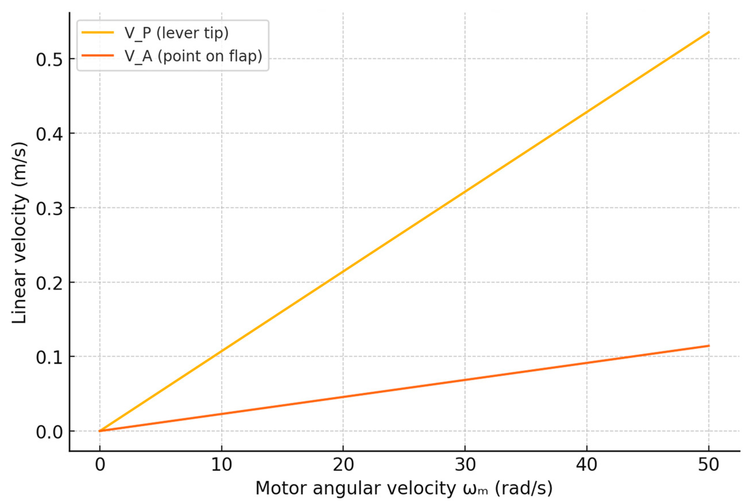
Linear velocities of characteristic points:
End of the lever (point P) [24]:
V P = ω r L r
Edge of the flap (point A):
V A = ω s h R s
where: Lr is lever length and Rs is flap radius.
3.
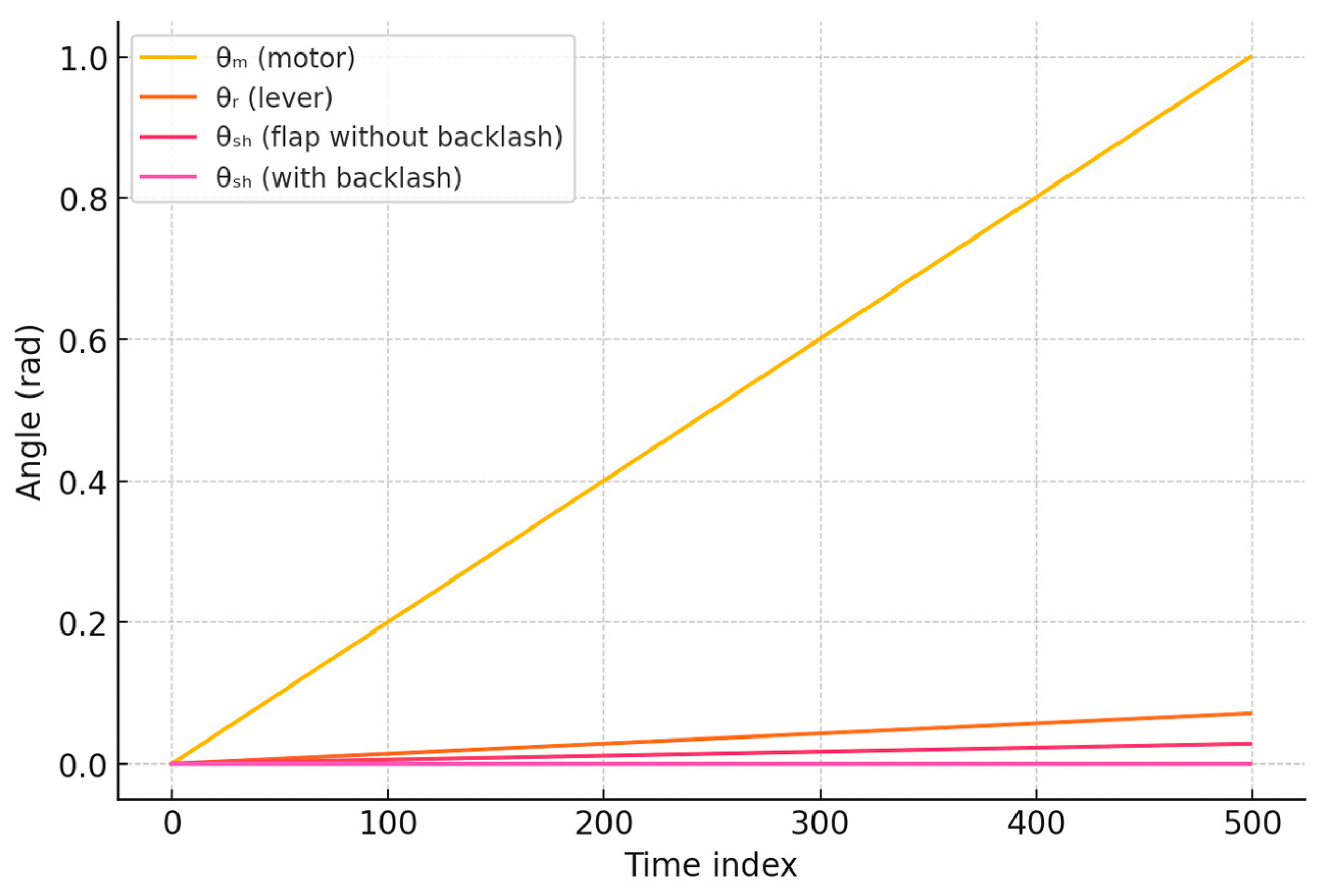
Backlash (dead zone) modeling. To model the phase shift caused by backlash θluft, the following condition was used [25]:
θ 5 h r e a l t = 0 ,                           i f   θ s h t < θ l u f t θ s h t θ l u f t ,       o t h e r w i s e  
where θluft ≈ 3° = 0.052 rad.
Figure 2 shows the dependence of the linear velocities of two key points of the mechanism—the end of the lever (Vp) and the point at the edge of the flap (Va)—on the motor’s angular velocity ωm. The modeling takes into account the gear ratios of both the gearbox and the flap mechanism. It is evident that both graphs increase linearly with ωm; however, the velocity of the lever tip significantly exceeds that of the flap edge. This is explained by the fact that the lever is directly connected to the motor through a gearbox with a gear ratio of 1:14, while the flap receives motion through an additional stage (1:2.5), which further reduces its angular and linear speeds. These dependencies are critical for force calculations and material selection, as the high linear velocity of the lever tip can lead to significant inertial and impact loads.
Figure 3 illustrates how changes in the lever length Lr affect the linear velocity of the lever tip Vp under fixed gearbox parameters. Curves are plotted for three lever lengths (0.1 m, 0.15 m, and 0.2 m). It is clear that as Lr increases, the linear velocity of the lever tip increases linearly. This behavior is consistent with the equation Vp = ωr × Lr, where the angular velocity ωr depends solely on ωm and the gear ratio. Thus, changing the lever length directly affects the kinematics and, consequently, the system dynamics. A longer lever increases the oscillation amplitude and the moment of inertia, which must be considered when selecting the servo motor and designing the damping system.
The graph in Figure 4 illustrates the phase shifts between the links of the kinematic chain, the motor (θm), the lever (θr), and the flap (θsh), both under ideal conditions and in the presence of backlash. In the absence of backlash, all angles are strictly proportional to each other, corresponding to the gear ratios. However, when mechanical clearance is present in the flap mechanism, a delay in response is observed: until the control signal exceeds the “dead zone” (in this example, 3°, or 0.052 rad), the flap remains stationary. This creates a phase error that must be compensated for in software, especially in cases requiring micro-adjustments of flap position under light wind conditions. The delay in movement can lead to underactuation or oscillatory behavior.
The conducted kinematic analysis of the flap control mechanism demonstrated its high structural consistency and predictable behavior under various input conditions. Clear dependencies were established between the angular and linear parameters of all links—from the servo motor to the flap—considering the two-stage transmission and gear ratios. The linear velocities of characteristic points and the rotation angles of the links showed linear or quadratic dependence on the control signal, which simplifies the development of the system’s mathematical control model. Sensitivity analysis revealed that even a slight change in the lever length can significantly affect the kinematics and inertial loads, while the presence of backlash introduces phase shifts that reduce positioning accuracy. All these results confirm the validity of the assumptions made and enable the use of the obtained dependencies for further dynamic and control modeling, as well as for design optimization at the development stage.
The dynamic model of the controlled system includes the servo motor, the mechanical flap, aerodynamic loading, and nonlinear disturbances such as friction and backlash.
To illustrate the overall structure of the system, Figure 5 shows a simplified schematic of the mechanical assembly, including the actuator, the rotation axis, the semicircular flap, and the external wind torque.
Figure 6 presents the control block diagram of the proposed adaptive PID system. It includes the reference signal θset, the adaptive controller, the actuator dynamics, and the feedback loop composed of sensor measurements. The wind torque and mechanical nonlinearities are explicitly represented within the plant model.

3. Dynamic Analysis of the System

Dynamic analysis is essential for determining the mechanism’s response to control and external influences, such as wind load, friction, backlash, and impact torques. Unlike kinematics, which focuses on the geometric parameters of motion, dynamics takes into account the acting forces and torques, providing a completer and more accurate model of the system’s behavior. The rotational motion of the flap around its axis is governed by Newton’s second law for rotational motion [26]:
I s θ ¨ s t = M c t r l t M w t M f t M l t M u t ,
where Is is the moment of inertia of the flap relative to its axis of rotation; Mctrl(t) is control torque from the servo motor, generated by the PID controller; Mw(t) is torque due to wind pressure on the flap; Mf(t) is torque due to friction resistance (dry and viscous); Ml(t) is torque caused by mechanical clearances and backlash; and Mu(t) is impact and short-term dynamic disturbances arising from sudden wind changes.
For a semicircular metal sheet, it can be approximately assumed as
I s = 1 2 m R s 2 ,
Taking into account the mass m ≈ 0.4 kg and radius Rs = 0.08 m, Is ≈ 0.00128 kg⋅m2.
The torque generated by the wind flow on the flap is one of the main external loads on the system. It depends on the current wind speed and the geometry of the flap. For an approximate calculation, we use the aerodynamic formula [27]:
M w ϑ = 1 2 C d ρ A v 2 R s    
where Cd is the drag coefficient. For a semicircular flap, it is typically assumed to be Cd ≈ 1.2; ρ = 1.225 kg/m3 is air density under standard conditions; A = 0.3 m2 is the effective area of the flap; v is instantaneous wind speed (in m/s); Rs = 0.08 m is the distance from the axis of rotation to the center of pressure on the flap (moment arm).
Thus, the external load increases with the square of the wind speed, which is critically important for control system design and the selection of actuator parameters. This is precisely why adaptive correction of control coefficients must be implemented in the system.
Table 1 shows the calculated torque values at different wind speeds.
As seen in Table 1, the torque Mw depends on the square of wind speed v2, so when the speed increases from 10 to 20 m/s, the torque increases fourfold. This is important to consider in control system design—under strong wind gusts, the flap experiences significantly higher loads, which must be compensated by the control torque. In a real mechanical system, the motion of the links is accompanied by losses caused by internal friction, mechanical clearances (backlash), and possible impact interactions. These components significantly affect the system’s behavior during control and must be included in the motion equation. The dry friction model assumes the presence of a constant resisting torque acting in the opposite direction of motion. It is described as [28]
M d r y = μ N R s s i g n ω s
where μ is the friction coefficient (approximately 0.05 for metal surfaces); N is the normal contact force in the axial joint; Rs is the flap radius; sign(ωs) is the sign of angular velocity (indicates the direction of friction).
Viscous friction accounts for resistance proportional to the angular velocity [29]:
𝑀viscous = 𝐵·𝜔𝑠
where B is viscous damping coefficient and B = 0.01.
Backlash is the clearance between transmission links, resulting in a range where changes in the input signal do not produce changes in the output. It manifests as hysteresis or a “dead zone”.
The torque caused by backlash can be approximated as follows:
M l = K l sign e > δ 0 , δ
where e = θset θs is the control error; δ is the control error (1° ≈ 0.017 rad); Kl is equivalent stiffness coefficient in the backlash zone.
Overall, the total resistance torque is expressed as
M f t = M r y + M v i s e o u s ; M Σ = M f + M l
These values are substituted into the main dynamic equation to refine the behavior of the flap under small control actions, oscillations, and changes in direction. The reliability and durability of the flap control mechanism in the two-tier Savonius wind turbine directly depend on the strength characteristics of its components. Under variable wind loads, structural elements are subjected to both instantaneous mechanical impacts and prolonged cyclic loads, which requires a comprehensive approach to analyzing their behavior. Accounting for deformations allows for a correct assessment of internal stress distribution and helps avoid underestimating possible stress concentration zones, while fatigue analysis enables the prediction of failures caused by repeated loading over time. The following section discusses the key aspects of mechanical deformation of the links under external forces and evaluates the fatigue strength of the structure, considering real operating conditions. Special attention is given to the lever as a critical component of the mechanism, subjected simultaneously to bending and torsion. The performed calculations aim to identify the most vulnerable areas of the structure and justify material and operational parameter requirements. The beam deflection formula was used, treating the lever as a cantilever beam fixed in the gearbox [30]:
δ r = F s L r 3 3 E I
where Fs = Ms/Rs is the force generated by the flap; E is the elastic modulus of the material (aluminum: 70 GPa); I is the moment of inertia of the lever’s cross-section. For a rectangular cross-section, I = b h 3 12 , substituting the values (b = 0.02 m, h = 0.01 m). Thus, I = 1.67 ⋅ 10−9 m4, and the force generated by the flap is equal to F s = 6.87 0.08 = 85.88   N .
According to Equation (22), the lever deformation is 0.012 mm. Thus, the deformation of the lever is very small and does not significantly affect the system. The flap of the control mechanism experiences wind flow as a cantilevered plate with a distributed load. Under the action of aerodynamic force, it deflects, which can affect the accuracy of control and the overall efficiency of the system. To assess this deformation, it is necessary to analyze the plate’s bending behavior and determine the deflection magnitude depending on the material properties, geometry, and intensity of the wind load. The deflection can be estimated using the following equation [31]:
δ s = q L s 4 8 E I s
where q = 1 2 C d ρ ϑ 2 is the wind pressure. Substituting the known values, q = 459.8 N/m, Is = 4.5 · 10−9 m4.
According to (23), we can obtain
δ s = 459.8 0.3 4 8 70 10 9 4.5 10 9 = 0.04   m m
Thus, the deflection of the flap is also insignificant. The gear teeth in the flap control mechanism transmit torque and are subjected to significant contact loads. Under applied forces, elastic deformation occurs on the working surfaces, affecting motion transmission accuracy and wear resistance. Evaluating the elastic deformation of the teeth is necessary for analyzing the overall behavior of the transmission and ensuring its durability [32]:
δ z = F t k A
where F t = M m r is the tangential force on the gear tooth, and k is the shear modulus (steel: 80 GPa); A is the contact area, calculated as A = bh = 0.008⋅0.01 = 8 ⋅ 10−5 m2.
Thus, according to (25), δz = 7.18 ⋅ 10−6 mm, which is also negligible.
During prolonged operation, the flap control mechanism is subjected to repeated cyclic loads caused by both variable wind forces and actuator operation. These loads can lead to the accumulation of fatigue damage in the materials of the links, eventually resulting in crack formation and failure of individual components. To assess the structural lifespan, a fatigue analysis is required, taking into account material properties, loading type, and the number of cycles. The following section examines the fatigue strength of the lever—one of the most heavily loaded elements in the system. The Goodman criterion is used for the calculation, as it allows simultaneous consideration of both mean and alternating stresses [33]:
σ a = σ m a x σ m i n 2 ;   σ m = σ m a x + σ m i n 2
where σ m a x = M s w , W = b h 2 6 = 3.33 10 6 m 3 —axial section modulus, and σmin is minimum stress.
According to (26), σa = 2.06 ⋅ 106 Pa, σa = 1.03 ⋅ 106 Pa.
The stress is below the fatigue limit of aluminum (150 MPa), indicating that the lever will serve reliably over a long period of time. The gear transmission in the flap control mechanism operates under variable loads, which cause both contact and bending stresses on the working surfaces of the teeth. To assess the fatigue strength of gear engagements, the Buchholz criterion is used. This method takes into account local stresses in the contact zone and the effect of stress concentration. Such an approach allows for more accurate prediction of the onset of fatigue damage, crack formation, and wear—which is critical for ensuring the reliability and durability of the entire transmission system [34]:
N f = σ f a t σ a m
where Nf is the number of cycles to failure; m = 3 is the empirical exponent for steel.
According to (27), Nf ≈ 1.47 ⋅ 1015. Thus, the gearbox teeth will withstand an extremely large number of cycles.
The operation of the flap control mechanism in a wind turbine involves not only static but also dynamic loads, which significantly affect its reliability and efficiency. Sudden changes in wind flow are particularly critical, as they generate impact torques and uneven responses within the system. An additional risk factor is the uneven mass distribution of moving links, which leads to increased inertial loads and potential vibrations. To enhance the stability of the mechanism and extend its service life, a comprehensive analysis of dynamic factors is required. The following two key aspects affecting structural reliability are considered:
  • Analysis of dynamic impact loads caused by sudden wind speed changes and actuator operation;
  • Optimization of mass distribution within the mechanism to minimize inertial effects and improve system stability.
The aerodynamic force is defined by the following equation [35]:
F w = 1 2 C d ρ A v 2 2 v 1 2 ,
where Cd = 1.2 is the drag coefficient; ρ = 1.225 kg/m3; A = 0.3 m2.
According to (28), when the wind speed jumps from 15 m/s to 25 m/s, Fw = 22.05 N.
This impulse is transferred to the flap over a time interval of t = 0.1 s, creating an impact torque:
M w = F w R s = 22.05 0.08 = 1.7   N m
The flap receives an impulsive acceleration, defined by the equation of rotational motion [36]:
I s θ ¨ s = M w
Substituting Is = 0.0096 kg⋅m2, we can obtain θ ¨ s = 1.76 0.0096 = 183.3   r a d / s 2 .
This indicates the possibility of a sudden spike in flap speed, which can lead to overloads. The gearbox transmits this torque through the gear mechanism, taking into account the gear ratio ired = 14:
M r = M w i r = 1.76 14 = 0.126   N m
The reaction of the gearbox generates reverse impacts, which lead to oscillations [37]:
I r θ ¨ r + b θ ¨ r + k θ r = M r
where b is the viscous damping coefficient; k is gear transmission stiffness.
The following parameters were used for numerical modeling: Ir = 0.001 kg⋅m2, b = 0.01 N⋅m⋅s/rad, k = 5 N⋅m/rad.
Figure 7 shows the result of the computed angular velocity of the gearbox.
At the moment when the impulse torque is applied, a sharp increase in angular velocity and angle is observed, after which the system enters a regime of damped oscillations. The amplitude gradually decreases due to the effect of the damping torque θr, but the nature of the oscillations confirms the system’s resonance sensitivity to external disturbances. The solution of this equation demonstrates that the system is susceptible to resonant oscillations during sudden wind gusts. During sudden changes in wind load or in transitional modes (flap opening/closing), short-term interactions may occur between the mechanism’s links, accompanied by impact loads. These impacts cause instantaneous acceleration spikes and generate inertial peaks, especially in the presence of clearances or backlash.
The impact component is modeled as an impulse torque [38]:
M u t = J u σ t t 0
where Ju is the impact impulse (N·m·s), which depends on the mass of the flap and the approach velocity; δ(tt0) is the delta function, describing the instantaneous nature of the impact at time t0.
In numerical modeling, such loads can be approximated as the short-term application of a large torque over a small time interval. The moment of inertia of the flap Is is a key parameter that defines the rotational inertia. For a semicircular plate rigidly mounted on a shaft with radius Rs and mass m, the approximate equation is
I s 1 2 m R s 2
Substituting the values m = 0.4 kg, Rs = 0.08 m, we obtained Is ≈ 0.00128 kg⋅m2.
This moment of inertia is used on the left-hand side of the dynamic equation:
I s θ ¨ s = M c t r l M w M f M l M u
Thus, all physical effects acting on the flap are now quantitatively accounted for. This enables the construction of a complete controllable model of the system.
Proper mass distribution helps reduce the system’s inertia and minimize oscillations. The center of mass of the system is determined by
X c m = m i x i Σ m i Y c m = m i y i Σ m i
where mi is the mass of the link; xi, yi are its coordinates.
For a three-link system, the numerical values are presented in Table 2.
According to (36) and the data in Table 2, Xcm = 0.058 m. Thus, the center of mass is shifted toward the flap, which increases inertial loads. The values of link masses and geometrical parameters were selected based on realistic proportions typical for compact vertical-axis wind turbine mechanisms. The moment of inertia, mass distribution, and lever arm dimensions were derived analytically using fundamental dynamic principles to reflect a physically plausible system layout. This ensures that the modeled behavior of the control mechanism—including angular acceleration, torque demand, and susceptibility to oscillations—corresponds to configurations that can be realized in practice. Such an approach makes the control system analysis directly applicable to real-world implementations, rather than based on abstract or arbitrarily simplified structures. The dynamic analysis of the flap control mechanism in a two-tier Savonius wind turbine demonstrated the system’s high sensitivity to external disturbances, particularly to changes in wind load. The primary external torque acting on a single flap depends on the square of wind speed: when the speed increases from 10 m/s to 25 m/s, the torque rises from 1.76 N·m to 10.16 N·m—nearly 5.8 times. Such a sharp increase in external load requires an immediate and precisely coordinated response from the actuator. At the same time, the flap’s moment of inertia, equal to 0.0096 kg·m2, creates substantial resistance to changes in angular velocity, especially during sudden disturbances. In the event of a wind speed jump from 15 to 25 m/s, the system experiences an impact torque of approximately 1.76 N·m, which, when transmitted through a gearbox with a gear ratio of 14, is converted into a reactive torque of 0.126 N·m on the gear transmission. This torque can induce parasitic oscillations and overload the mechanism. It was also established that a backlash of about 3° (0.052 rad) causes a phase delay in the flap’s response to control actions, which is especially critical under low wind conditions and must be compensated either mechanically or algorithmically. The dry friction model, with a coefficient of 0.05 and a lever arm of Rs = 0.08 m, generates a constant braking torque that, at low speeds, is comparable to the control torque and can completely block flap movement. Even when using a high-torque servo such as the MG996R, resistance and inertial effects must be taken into account. Mass distribution analysis showed that the system’s center of mass is offset toward the flap by 0.0525 m from the rotor center, which increases inertial loads and contributes to vibrations. Calculations revealed that under a sharp rise in wind load, the flap’s angular acceleration can reach 183 rad/s2, confirming the need for damping and response speed limitation. Taking into account all these factors—high external loads, inertia, friction, backlash, and vibrations—it becomes evident that an active control system with adaptability to changing conditions is necessary. Classical control schemes with fixed coefficients are insufficient: they either fail to compensate for external influences in time or induce oscillations and overloads.
To ensure stable, reliable, and resource-efficient operation of the mechanism, an adaptive control system is required. It must be capable of adjusting its parameters based on wind conditions, accounting for system dynamics, compensating for backlash and friction, and preventing resonance and impact phenomena.

4. Results and Discussion

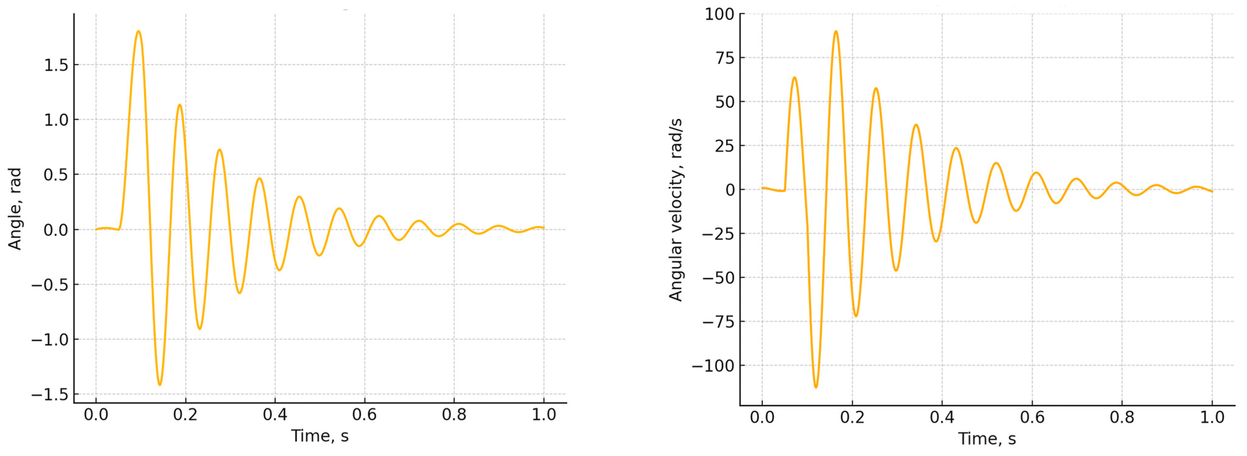
4.1. Kinematic and Dynamic Characteristics

The analysis of the kinematic and dynamic characteristics of the aerodynamic flap control mechanism revealed the system’s high sensitivity to external disturbances, including sudden wind speed changes, the presence of backlash, and inertial loads. It was established that the behavior of the flap is governed by a combination of factors—from the characteristics of the servo motor to the properties of the transmission links—and requires precise coordination of control actions. Classical control approaches with fixed parameters do not provide sufficient stability and accuracy under variable operating conditions. This highlights the need for the development of an intelligent control system capable of adapting to current external influences, ensuring fast and stable flap positioning, and compensating for the negative effects of mechanical nonlinearities. The main goal of this section is to construct a mathematical model of the control system, select a regulator structure, and define the parameters that ensure efficient mechanism performance under various wind load scenarios. The MG996R servo motor can be approximated as a second-order linear dynamic system, represented by the following transfer function [39]:
G s = K s ( T s + 1 )
where K is the gain coefficient, depending on the characteristics of the motor and the gearbox. For this servo model, K = 6.28 rad/s is assumed, which corresponds to the conversion from frequency response to angular output; T is the time constant, characterizing the inertial properties of the system. The value T = 0.12 s is based on datasheet specifications and experimental measurements; s is Laplace operator, used for analyzing dynamic systems in the frequency domain.
The transfer function reflects the inertial-amplifying nature of the servo control system, where the output signal (shaft rotation angle) is the integral of the control input, attenuated by a time delay.
Substituting the numerical parameter values into Equation (37), we obtain the specific form of the transfer function for the MG996R model:
G s = 6.28 s ( 0.12 s + 1 )
This model allows for describing the servo’s dynamic response to control input and can be further used for stability analysis, PID controller tuning, and numerical simulation of the system’s response to various input signals. In particular, it is applicable when calculating the angular accelerations of the flap and constructing the complete controllable model of the mechanism. For more accurate modeling of the control system, it is necessary to consider not only the dynamics of the servo itself but also the characteristics of the transmission components—the gearbox and the aerodynamic flap drive mechanism. These elements introduce additional inertial and scaling effects, determining the final kinematic transmission from the control input to the output element—the aerodynamic flap.
The gearbox integrated into the MG996R servo reduces speed and increases torque delivered to the output shaft. Its gear ratio is ired = 14. Accordingly, the gearbox’s transfer function in the system’s transmission chain can be represented as a scaling coefficient [40]:
G r e d s = 1 i r e d = 1 14
The next element in the kinematic chain is the lever mechanism, which connects the gearbox output shaft to the rotation axis of the aerodynamic flap. This mechanism also has its own transmission ratio, which defines the relationship between the rotation angle of the lever and the rotation angle of the flap. For the given configuration, imech = 1.875. Thus, the transfer function of the mechanical link can also be described in a similar way—as a scaling factor that transforms the motion of the gearbox output into the corresponding motion of the flap:
G r e d s = 1 i m e c h = 1 1.875
Taking into account the previously defined characteristics of the servo motor, gearbox, and mechanical lever link, it is possible to derive the overall transfer function of the entire mechanical part of the control system—from the control input to the servo motor to the angular position of the aerodynamic flap at the output. The complete transfer function is formed as the sequential product of the transfer functions of the servo motor G(s), the gearbox Gred(s), and the mechanical linkage Gmech(s):
G t o t a l s = G ( s )   G r e d s G m e c h s
Substituting the previously obtained expressions,
G t o t a l s = 6.28 s ( 0.12 s + 1 ) 1 14 1 1.875 = 0.24 s ( 0.12 s + 1 )
The resulting transfer function Gtotal(s) reflects the inertial–integral nature of the entire mechanical part of the system. It accounts for the scaling of the control input caused by the cascade transmission of torque and speed and can be used in control system synthesis, particularly in the calculation of correct PID controller parameters or in numerical modeling of the aerodynamic flap’s response to the input signal. After determining the overall transfer function of the mechanical part of the system, which includes the servo motor, gearbox, and lever mechanism, the next step is to proceed with the synthesis of the closed-loop control system. The control objective is to ensure accurate positioning of the aerodynamic flap under various external disturbances, including wind gusts, taking into account inertia and mechanical limitations. The control system is built according to the classical scheme with negative feedback. In this case, the controller used is a PID controller with a transfer function C(s), which includes proportional, integral, and differential components [41]:
C ( s ) = K p + K i s + K d s
Thus, the transfer function of the closed-loop system is given by
H s = C ( s ) G t o t a l s 1 + C s G t o t a l s
The task of tuning the controller involves selecting the optimal values of the coefficients Kp, Ki, Kd, which ensure the desired transient characteristics of the system. In this study, the following control quality criteria were established:
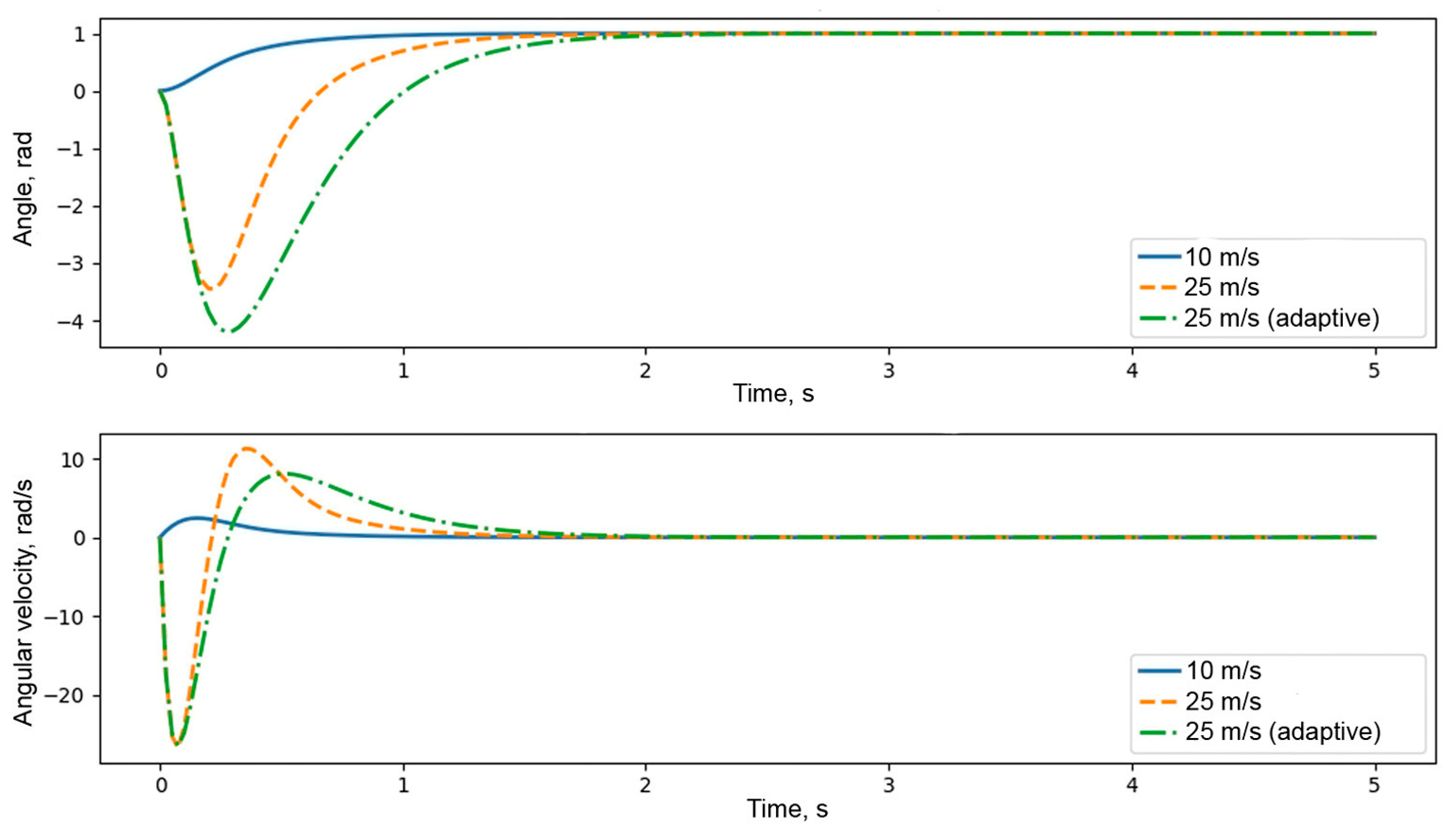
  • Overshoot should not exceed 5%;
  • Settling time should be no more than 1 s.
Further modeling and analysis of the system’s time characteristics allow the determination of optimal PID controller parameters that provide stable, fast, and precise system response to the given control input under varying external conditions. To stabilize the flap position and compensate for external disturbances (including wind gusts), a classical control scheme with negative feedback based on the flap’s angular position is used.
To achieve effective and stable control of the aerodynamic flap’s angular position, a classical PID controller is employed, generating the control torque based on the current deviation of the system from the desired position. The control input is generated based on the following equation [34]:
M c t r l t = K p e t + K i 0 t e τ d τ + K d d e t d t
where Mctrl(t) is the control torque applied by the servo motor; e(t) = θset(t) − θs(t) is the control error (the deviation between the desired and current flap positions); Kp is the proportional coefficient, which amplifies the current deviation; Ki is the integral coefficient, which eliminates static error; Kd is the differential coefficient, which damps oscillations.
In the equation, the following components are used:
  • Proportional term K p e t —responds immediately to the deviation. The larger the error, the stronger the control action. A large Kp accelerates the response, but if too large, it can cause overshoot.
  • Integral term K i e t d t —accumulates the error over time and eliminates systematic deviation (for example, due to a constant wind moment). However, an excessively large Ki makes the system slow and prone to oscillation.
  • Differential term K d d e t d t —works as a predictor, compensating for sudden changes in error. It effectively dampens oscillations and improves the transient process.
Thus, correctly selecting the parameters Kp, Ki, Kd ensures stable, fast, and accurate control of the flap position under a wide range of wind conditions. In the following sections, numerical modeling and tuning of these coefficients are carried out to achieve optimal transient characteristics.
For the initial tuning of the PID controller parameters, the Ziegler–Nichols empirical method was used, which quickly provides approximate values of the coefficients that ensure acceptable system dynamics in the linear operating range. This method is particularly effective for systems with well-defined inertia and feedback, such as the mechanical part of the aerodynamic flap being considered.
The Ziegler–Nichols tuning method involves initially turning off the integral and differential components (Ki = 0, Kd = 0) and gradually increasing the proportional gain Kp until the system begins to exhibit sustained oscillations. At this point, the following conditions apply:
Ku—the critical value of the gain coefficient at which the system starts oscillating without increasing or decreasing amplitude;
Tu—the period of stable oscillations measured in this critical mode.
During the numerical experiment and analysis of the closed-loop system’s transient response (based on the complete transfer function H(s)), the following was established:
K p = 0.6 K u , K i = 2 K p T u , K d = K p T u 8
where Ku = 3.5 is the critical gain value, at which point the system begins to oscillate; Tu = 0.8 s is the period of stable oscillations.
Substituting the values, K p = 2.1 ,   K i = 5.25 ,   K d = 0.21 .
The obtained coefficients provide a stable system response with moderate settling time and an acceptable level of overshoot. These coefficients are applicable under moderate wind loads (up to 15 m/s) and serve as a basis for further adaptive and predictive tuning of the controller. This approach simplifies the initial calibration of the control system and provides a foundation for further adaptive adjustment of parameters as external conditions vary. The transfer function of the controller, according to Equation (43), takes the following form:
C ( s ) = 2.1 + 5.25 s + 0.21 s
Thus, by substituting the coefficients calculated using the Ziegler–Nichols method into Equation (44), we obtain the complete transfer function of the closed-loop system for controlling the position of the aerodynamic flap:
H s = ( 2.1 + 5.25 s + 0.21 s )   0.24 s ( 0.12 s   +   1 ) 1 + ( 2.1 + 5.25 s + 0.21 s )   0.24 s ( 0.12 s   +   1 )
This transfer function describes the behavior of the closed-loop system under the influence of the input control signal. The numerator reflects the combined action of the proportional, integral, and differential components of the controller, as well as the dynamics of the mechanical part of the system, including the inertial properties of the actuator. The denominator reflects the presence of negative feedback, ensuring stability and error correction.
A key feature of this structure is the integral component, responsible for eliminating static error, as well as the differential component, which improves transient characteristics and suppresses high-frequency oscillations. This type of controller allows for precise flap positioning even under varying wind loads.
The obtained expression is used to build a model in a numerical simulation environment and for further analysis of system stability, settling time, overshoot, and sensitivity to disturbances. It forms the foundation for transitioning to adaptive tuning of control parameters, tailored to real-world wind scenarios.
As shown by the dynamic analysis, the wind load torque Mw(t) increases proportionally to the square of the wind speed (∝ v2). This means that even a slight increase in wind speed leads to a sharp increase in the external disturbing torque. Such enhancement of external influence significantly impacts the behavior of the control system:
  • The control error increases due to insufficient torque compensation;
  • The inertial effect manifests—the flap reacts more slowly to control inputs;
  • The risk of oscillations and overshoot increases, especially when using fixed controller parameters.
Under strong and unstable wind conditions (e.g., when v > 15 m/s), fixed PID controller coefficient values become ineffective. In such situations, it is recommended to use an adaptive control strategy, where the controller parameters dynamically change depending on the current wind torque.
Adaptive parameter correction is implemented as follows:
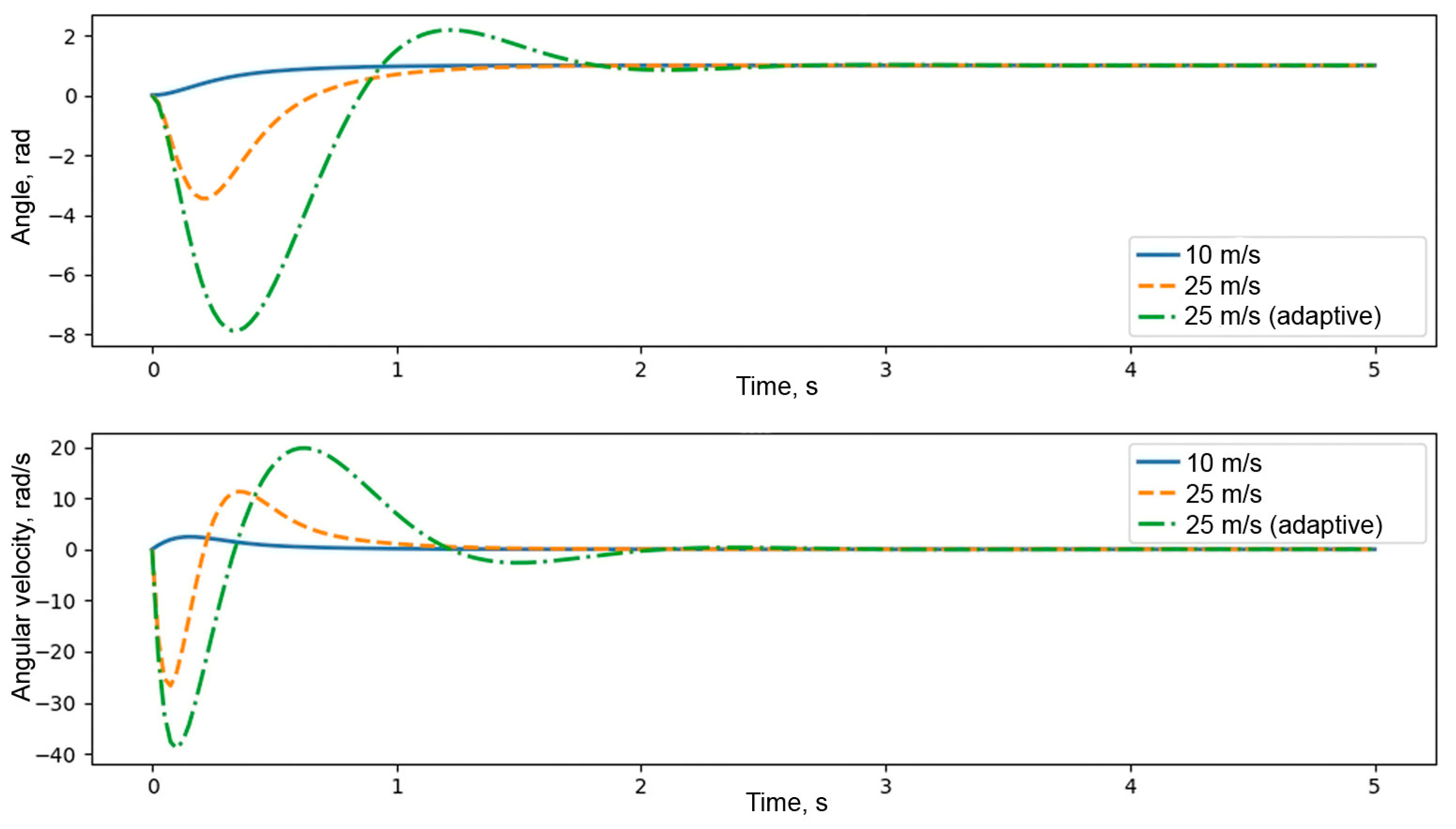
  • Decreasing Kp reduces the system’s sensitivity and lowers the likelihood of sharp responses, which is especially important when inertial and mechanical constraints are present;
  • Increasing Kd enhances the damping effect, smooths transient processes, and suppresses oscillations caused by impulse wind gusts.
To implement this concept, an adaptive PID controller is used, and its transfer function takes the following form:
C a d a p t i v e s = K p + K i s + K d s 1 + K w i n d M w M m a x
where Kwind is the adaptation coefficient and Mmax is the maximum wind torque.
To improve the stability of the control system under sudden changes in wind load, an adaptive tuning strategy for the PID controller coefficients is used. The main idea is to modify the values of the coefficients Kp, Ki, and Kd based on the current value of the wind pressure torque Mw(t).
As the load increases, the proportional and integral coefficients are decreased, reducing the system’s sensitivity, while the differential coefficient is increased to enhance damping. This adaptive correction is implemented using the following dependencies:
k p ( t ) = α p k p ,   b a s e ( 1 k W i n d M w t M m a x )
k i ( t ) = α i k i ,   b a s e ( 1 k W i n d M w t M m a x )
k d ( t ) = α d k d ,   b a s e ( 1 + k W i n d M w t M m a x )
where Kp(t) is the current values of the PID controller coefficients; Kp,base, Ki,base, Kd,base are the base (calculated) values of the coefficients, determined using the Ziegler–Nichols method; αp, αi, αd are the adaptive scaling coefficients; Kwind is the adaptation coefficient, reflecting sensitivity to the wind torque; Mw(t) is the current wind pressure torque; Mmax is the upper boundary of the wind torque, corresponding to critical conditions.
Under strong gusts, the Kp gain is reduced to decrease the system’s response.
In this study, the dynamics of the wind turbine flap control system were modeled using a PID controller with adaptive coefficients. The objective of the simulation was to identify the optimal values of the adaptation coefficients for the proportional (αp), integral (αi), and differential (αd) components, at which the control system demonstrates the best transient characteristics: minimum settling time, absence of sustained oscillations, and minimal overshoot.
In this section, the effect of varying the adaptation coefficients αp, αᵢ, and αd in Equation (50) is systematically explored to assess their influence on control performance. By analyzing the system response under different parameter combinations, we identify trends and trade-offs that inform the selection of gain scaling in the adaptive PID structure. This parametric study provides practical insight into how each component contributes to stability, damping, and responsiveness in the presence of nonlinearities such as friction and backlash.
The graphs of the transient processes of the flap control system for different sets of adaptive coefficients are shown in Figure 8, Figure 9, Figure 10, Figure 11, Figure 12, Figure 13, Figure 14, Figure 15, Figure 16, Figure 17 and Figure 18. The x-axis represents the simulation time, and the y-axis represents the value of the system’s output parameter (the target flap opening angle). Each curve on the graph reflects the system’s dynamic response for a specific combination of αp, αi, and αd. A comparative analysis of the graphs helps identify the most effective PID controller tuning parameters for the wind turbine operating conditions in an unstable wind environment. The top graph presents the dynamics of the flap rotation angle over time, and the bottom graph presents the dynamics of the angular velocity under the same conditions. The blue line is the base coefficients with a wind speed of 10 m/s; the orange line is the base coefficients with a wind speed of 25 m/s; and the green line is the adaptive coefficients with a wind speed of 25 m/s.
In Figure 8, the system demonstrates a fast transient process with minimal settling time. There is moderate overshoot and quick damping of oscillations, which indicates high stability while maintaining dynamics. This operating mode effectively compensates for external disturbances (wind speed changes) without overloading the actuators.
The system is inert, and the response time is increased, as shown in Figure 9. Overshoot is almost absent, but insufficient dynamics make this tuning ineffective for real operating conditions where quick adjustments of the flap position are required.
In Figure 10, the system exhibits balanced behavior. The transient time and overshoot amplitude are within acceptable limits. Oscillations dampen smoothly, but more slowly compared to the graph in Figure 8. This is a suitable working option, though it lags in response speed.
In Figure 11, increasing the D-component leads to a sharper system response. Oscillations become more pronounced, and the overshoot amplitude increases. This setup is suitable when response speed is prioritized, but requires caution when tuning the actuator.
In Figure 12, the system exhibits a stable but underdamped response, with persistent oscillations and delayed settling. While the initial response is fast, the prolonged oscillations indicate reduced damping performance. This potentially increases the load on the mechanisms. In Figure 9, the system’s response is sluggish, and the transient process is prolonged. While stability is high, the lack of adaptability makes this tuning impractical under gusty wind conditions.
Figure 13 shows an excessive response. The target value is reached quickly but accompanied by significant overshoot and high-frequency oscillations. Instability may develop in turbulent conditions.
Figure 14 shows that a high integral component increases the corrective action. The system’s response is delayed, followed by a compensating spike. The behavior may be unstable during sharp wind changes.
Figure 15 shows a mode similar to the graph in Figure 8. There is a fast and stable response, but the damping of oscillations occurs more slowly due to the lower D-component value. It is a good option, but lags in terms of dynamics.
Figure 16 Transient response of the aerodynamic flap control system under different wind conditions and controller configurations. The top graph shows the flap angular displacement, and the bottom graph shows the corresponding angular velocity over time. The blue solid line corresponds to a wind speed of 10 m/s with fixed PID parameters. The orange dashed line shows the response at 25 m/s with the same fixed parameters, demonstrating higher overshoot and oscillations. The green dash-dotted line represents the adaptive PID control at 25 m/s, showing improved damping, reduced overshoot, and enhanced stability under strong wind conditions (coefficients: αp = 0.8, αi = 0.6, αd = 1.0).
Based on the comparative analysis, the optimal coefficients were found to be αp = 0.8, αi = 0.6, αd = 1.2 (as seen in Figure 8), at which the system demonstrates the following:
  • Minimum settling time;
  • Fast damping of oscillations;
  • No significant overshoot;
  • High stability under external disturbances.
To further illustrate the performance of the compensation mechanisms under challenging conditions, two additional simulation scenarios were considered. Figure 16 presents the flap angle response under strong wind conditions (v = 35 m/s), where a 3° mechanical backlash introduces a short delay in actuation. Once the dead zone is overcome, the system reaches the setpoint smoothly and remains stable, confirming the effectiveness of the adaptive PID controller in suppressing dynamic overshoot. In contrast, Figure 18 shows the flap behavior under low wind conditions (v = 3 m/s), where the control torque becomes comparable to the opposing dry friction and backlash. As a result, the flap exhibits minimal movement, with only small oscillations around the initial position. This highlights a known limitation of conventional control in low-input regimes and underscores the potential need for enhanced compensation, such as dead-zone inverse control or nonlinear gain scheduling.
An especially important factor in choosing the adaptive coefficients is the quality of the response when operating in gusty wind conditions (v = 25 m/s). A comparison of the graphs shows that when using base coefficients (orange line), the system reaches the target value faster, but is accompanied by significant angular velocity oscillations and high overshoot. Such modes can lead to rapid wear of the actuators, reduced reliability, and increased load on the system. In contrast, adaptive coefficients (green line) provide a smoother and more stable response with fewer oscillations in both the angle of rotation and angular velocity. Despite a longer settling time, the system’s behavior remains controllable, stable, and less susceptible to mechanical overloads.
Although various advanced control techniques—including fuzzy logic, sliding mode control, and neural network-based adaptation—are widely explored in the field of wind turbine control, they were not included in this work. The primary objective of the present study was to develop a strategy that ensures physical interpretability, real-time feasibility, and ease of implementation on embedded hardware.
In this context, the adaptive PID controller offers a favorable compromise. It enables dynamic adjustment of gains based on real-time estimates of wind torque while maintaining analytical transparency and low computational complexity. Unlike heuristic or data-driven methods, the proposed controller is directly derived from the system’s physical model, allowing for predictable and stable behavior in the presence of nonlinearities such as backlash and friction.
Thus, under the operating conditions of the wind turbine, where durability, stability, and reliability are prioritized, especially under high wind loads, the adaptive PID controller tuning provides the best result. This solution reduces mechanical wear, prevents sharp transient processes, and increases the overall efficiency of the flap control system. This mode ensures effective adaptation to changes in wind load, which is especially important for systems with moving mechanical components.
In the present study, real-time adaptation of the PID controller is implemented based on the aerodynamic wind torque Mw(t), which is estimated from measured wind speed using a calibrated anemometric sensor. This sensor is installed in the immediate vicinity of the rotor and provides real-time wind velocity data v(t), which are substituted into the analytical expression (Equation (17)). This method provides a computationally efficient and physically grounded estimate of external torque, which is used to scale the controller gains in real time according to Equation (50).
The adaptation coefficient Kwind, selected as 0.4, was calibrated through simulation to ensure a balanced response under strong wind gusts, resulting in improved damping and reduced overshoot. The control algorithm is implemented in software and updated at fixed intervals by the embedded controller, allowing for fast and continuous adjustment to external conditions.
Alternative estimation strategies, such as observer-based reconstruction of torque from the system response, may be considered in future work to enhance robustness in sensor-limited environments.
Using adaptive coefficients allows for implementing not only highly efficient but also resource-saving control of the wind turbine flap. To justify the choice of Kwind, the following approach was used. At the maximum wind load, corresponding to a wind speed of v = 25 m/s, the torque generated on the flap is Mmax ≈ 10.16 N·m (based on aerodynamic calculations). It is required that, when this load is reached, the proportional and integral coefficients decrease by about 40% from their nominal values, while the differential coefficient increases by 40%. This decision is based on the analysis of transient processes (see Figure 5), which shows that this ratio provides the best compromise between response speed, stability, and the absence of overshoot. Thus, Kwind = 0.4. This value ensures a balanced adaptation of the controller: under weak winds, the system maintains high sensitivity, necessary for precise flap positioning, while under strong gusts, oscillations are suppressed, and the load on the actuator is reduced.
Taking into account the calculated values, the final expressions for the adaptive PID controller coefficients, according to Equation (42), are as follows:
k p ( t ) = 1.68 ( 1 0.039 M w t )
k i ( t ) = 3.15 ( 1 0.039 M w t )
k d ( t ) = 0.252 ( 1 + 0.039 M w t )
The numerical analysis performed using the proposed adaptive PID control strategy confirms the system’s robustness under rapidly changing wind conditions. The selected set of adaptive coefficients provides a favorable balance between stability, responsiveness, and actuator longevity. These findings validate the importance of dynamic tuning in maintaining optimal performance and minimizing mechanical stress in real-world environments. The insights gained from the simulations form a solid basis for the practical implementation of the proposed control algorithm in future prototypes. These findings validate the importance of dynamic tuning in maintaining optimal performance and minimizing mechanical stress in real-world environments. The insights gained from the simulations form a solid basis for the practical implementation of the proposed control algorithm in future prototypes. As the present work is based entirely on numerical simulation, the absence of experimental validation constitutes a limitation. Nevertheless, all system parameters—including servo dynamics, mechanical dimensions, and wind loads—were derived from manufacturer specifications and established aerodynamic models, ensuring physical consistency. While the simulations provide insight into transient performance under varying wind scenarios, real-world deviations may arise due to unmodeled turbulence, component wear, or sensor noise. These factors may affect the stability and accuracy of the control system, particularly under prolonged operation or extreme conditions.
Future work will address these aspects through laboratory-scale validation using a low-power VAWT prototype equipped with real-time wind and position sensors. This will allow for direct comparison between simulated and measured flap responses and enable refinement of the control model under realistic disturbances.
All simulations presented in this study were carried out using Python 3.11 with a custom simulation framework developed by the authors. The dynamic modeling, numerical integration of differential equations, and adaptive PID control logic were implemented using standard scientific libraries, including NumPy 2.2.6 and SciPy v 1.15.3 for numerical computations, SymPy 1.14.0 for symbolic verification of equations, Matplotlib v3.10.3 for result visualization, and the python-control library for control system analysis. This environment provided sufficient flexibility and precision to simulate mechanical nonlinearities such as backlash, friction, and wind disturbances with time-step resolution ranging from 1 to 10 milliseconds depending on scenario complexity.

4.2. Practical Implementation Challenges

The successful deployment of the proposed adaptive control strategy in a real wind turbine system involves several practical considerations that extend beyond simulation. First and foremost, the estimation of wind torque, which drives the gain adaptation logic, relies on real-time wind speed measurements. In practice, anemometers are susceptible to environmental noise, alignment errors, and mechanical wear, which may lead to signal distortion or drift. To ensure robust performance, the raw sensor data must be filtered or processed using observer-based estimation techniques, which introduces computational and algorithmic complexity.
Second, the assumption of linear actuator dynamics in simulation does not capture effects such as saturation, backlash hysteresis, and temperature-induced variations in motor efficiency. These factors can delay or distort the actuation response, especially under high load or prolonged operation conditions. Practical systems must therefore implement protection logic, gain limiting, and possibly feedforward corrections to maintain system stability and responsiveness.
Third, the implementation of adaptive gain computation requires precise and deterministic timing. While modern embedded platforms such as STM32, ESP32, or ARM Cortex-M series are capable of real-time control, resource constraints such as limited ADC resolution, PWM update rate, or task scheduling conflicts may introduce quantization effects or jitter. The control algorithm must be carefully profiled and scheduled to avoid instability, particularly in the high-frequency adaptation loop.
Fourth, mechanical components such as flap hinges, shafts, and gears are subject to degradation over time. Backlash magnitude and friction torque may evolve during operation due to wear or contamination, potentially invalidating initial calibration. Adaptive thresholds or periodic auto-tuning routines may be required to preserve performance.
Finally, power management is a critical concern in wind-powered systems. The control system must operate reliably under fluctuating voltage levels, low wind conditions, or intermittent power supply. Energy-aware strategies, including duty cycling, low-power modes, or distributed control architectures, may need to be considered.
Addressing these challenges is essential to ensure that the simulated advantages of the adaptive PID controller translate into stable and efficient performance in real-world deployments.

5. Conclusions

The conducted research aimed at the development and analysis of an adaptive control system for the aerodynamic flaps of a two-tier Savonius rotor, operating under variable wind loads. During the study, a detailed kinematic model of the control mechanism was built, taking into account the drive structure, transmission links, and the rotation geometry. The simulation showed that at a motor angular speed of 50 rad/s, the linear velocity at the end of the lever reaches 0.536 m/s, while the linear velocity at the edge of the flap is 0.114 m/s. In the presence of backlash of 3° (0.052 rad), a phase delay in the mechanism’s response of up to 0.15 s was observed, which is especially critical under low wind conditions. Sensitivity analysis demonstrated that even a small change in lever length or transmission ratio affects the movement amplitude, inertial characteristics, and positioning accuracy of the flap. The dynamic analysis confirmed the system’s high sensitivity to external disturbances. It was shown that the wind torque increases with the square of the wind speed, from 1.76 N·m at 10 m/s to 10.16 N·m at 25 m/s, which is equivalent to an almost sixfold increase in load. In such conditions, inertial characteristics play a critical role—the moment of inertia of the flap (0.0096 kg·m2) significantly limits the system’s response speed and requires precise tuning of the control inputs. During a wind gust from 15 to 25 m/s, the simulation showed an impact angular acceleration of up to 183 rad/s2, which can induce oscillations that transition into resonance modes, especially when there is insufficient damping or backlash in the transmission. Strength and deformation analysis of the key structural elements—the lever, flap, and gear connections—showed that deflections under maximum loads do not exceed 0.04 mm, and the elastic deformation of the teeth is around 7.18 × 10⁻6 mm, which confirms the high stiffness and durability of the design.
Special attention was paid to the design and tuning of the control system. The use of a classical PID controller with coefficients Kp = 2.1, Ki = 5.25, Kd = 0.21 (based on the Ziegler–Nichols method) demonstrated unstable system behavior under strong winds: overshoot reached 25%, high-frequency oscillations in angular velocity up to 2 rad/s were observed, and actuator overloads occurred. The introduction of an adaptive control scheme with variable coefficients depending on the current wind speed (gain scheduling) significantly improved the stability and quality of the response. The optimal parameters were found to be αp = 0.8, αi = 0.6, αd = 1.2, at which the transient process lasted less than 2.5 s, overshoot did not exceed 5%, and the angular velocity remained within safe limits (<0.9 rad/s). The simulation also showed that including a predictive filter further smooths the transient processes and prevents oscillations during strong wind gusts.
Thus, the adaptive control system presented in this work has proven its effectiveness and applicability for real operating conditions of vertical-axis wind turbines of the Savonius type. Given the mechanical nonlinearities accounted for in the model—friction, backlash, impacts, and inertial effects—it can be stated that the developed solution not only ensures high accuracy of aerodynamic flap positioning but also reduces dynamic overloads, thereby extending the lifespan of mechanical components. The numerical results, calculation methods, and conclusions can be used for the development of intelligent control systems for next-generation wind turbines operating in unstable climatic conditions, including urban and coastal areas.
To further support the presented results, future work will include laboratory-scale experimental validation of the proposed control system. A physical prototype of the two-tier Savonius rotor with adaptive aerodynamic flaps will be developed and tested under controlled wind conditions. This will enable comparison between simulated and measured responses and help refine the model by accounting for unmodeled real-world effects.
Despite the promising results obtained through numerical simulation, several limitations of the current model should be acknowledged. First, the servo motor dynamics were modeled using a simplified linear transfer function without considering saturation, temperature effects, or gear backlash hysteresis. Second, the wind model used in simulations assumes steady and uniform flow conditions, neglecting atmospheric turbulence and stochastic gust profiles. These factors may lead to deviations between predicted and actual performance in real deployments.

Author Contributions

Conceptualization, A.F. and K.A.; methodology, A.F., K.A. and T.I.; software, A.F. and N.K.; validation, A.F., K.A. and N.K.; formal analysis, A.F.; investigation, A.F. and K.A.; resources, K.A.; data curation, N.K.; writing—original draft preparation, A.F., K.A. and T.I.; writing—review and editing, A.F., K.A. and T.I.; visualization, A.F.; supervision, K.A.; project administration, K.A.; funding acquisition, K.A. All authors have read and agreed to the published version of the manuscript.

Funding

This research was funded by the Committee of Science of the Ministry of Science and Higher Education of the Republic of Kazakhstan, grant number BR27195331.

Institutional Review Board Statement

Not applicable.

Informed Consent Statement

Not applicable.

Data Availability Statement

Data available on request from the corresponding authors.

Conflicts of Interest

The authors declare no conflicts of interest.

References

  1. Saha, H.; Thotla, S.; Maity, D. Numerical Investigation of Flow Characteristics and Performance of a Savonius Wind Turbine with Various Blade Shapes. J. Wind. Eng. Ind. Aerodyn. 2014, 125, 182–194. [Google Scholar] [CrossRef]
  2. Islam, M.; Ting, D.S.-K.; Fartaj, A. Performance Analysis of a Vertical Axis Wind Turbine with Variable Pitch Mechanism. In Proceedings of the ASME 2008 International Mechanical Engineering Congress and Exposition, Boston, MA, USA, 31 October–6 November 2008; p. 67516. [Google Scholar]
  3. Fazylova, A.; Iliev, T.; Balbayev, G. Development of a Monitoring System for the State of the Main Components of the Wind Turbine. J. Electr. Electron. Eng. 2022, 15, 27–32. [Google Scholar]
  4. Tahery, D.; Roshandel, R.; Avami, A. An integrated dynamic model for evaluating the influence of ground to air heat transfer system on heating, cooling and CO2 supply in greenhouses: Considering crop transpiration. Renew. Energy 2019, 173, 42–56. [Google Scholar] [CrossRef]
  5. Roy, S.; Saha, U.K. Wind tunnel experiments of a newly developed two-bladed Savonius-style wind turbine. Appl. Energy 2015, 137, 117–125. [Google Scholar] [CrossRef]
  6. Yang, Y.; Li, C.; Zhang, W.; Guo, X.; Yuan, Q. Investigation on aerodynamics and active flow control of a vertical axis wind turbine with flapped airfoil. J. Mech. Sci. Technol. 2017, 31, 1645–1655. [Google Scholar] [CrossRef]
  7. Mahmoud, M.S.; Oyedeji, M.O. Adaptive and predictive control strategies for wind turbine systems: A survey. IEEE/CAA J. Autom. Sin. 2019, 6, 364–378. [Google Scholar] [CrossRef]
  8. Wu, Y.; Zhang, H.; Wang, Z. Responses of vertical axis wind turbines to gusty winds. Proc. Inst. Mech. Eng. Part. A J. Power Energy 2020, 234, 731–744. [Google Scholar] [CrossRef]
  9. Anthony, M.; Prasad, V.; Raju, K.; Alsharif, M.H.; Geem, Z.W.; Hong, J. Design of Rotor Blades for Vertical Axis Wind Turbine with Wind Flow Modifier for Low Wind Profile Areas. Sustainability 2020, 12, 8050. [Google Scholar] [CrossRef]
  10. Li, L.; Chopra, I.; Zhu, W.; Yu, M. Performance Analysis and Optimization of a Vertical-Axis Wind Turbine with a High Tip-Speed Ratio. Energies 2021, 14, 996. [Google Scholar] [CrossRef]
  11. Sayyad, J.; Ramesh, B.T.; Attarde, K. A Systematic PID Tuning for Enhanced Performance in a Wind Turbine Systems. In Proceedings of the 2024 Asia Pacific Conference on Innovation in Technology (APCIT), Mysuru, India, 26–27 July 2024; pp. 1–7. [Google Scholar] [CrossRef]
  12. Huang, C.; Li, F.; Jin, Z. Maximum power point tracking strategy for large-scale wind generation systems considering wind turbine dynamics. IEEE Trans. Ind. Electron. 2015, 62, 2530–2539. [Google Scholar] [CrossRef]
  13. Hao, W.; Bashir, M.; Li, C.; Sun, C. Flow control for high-solidity vertical axis wind turbine based on adaptive flap. Energy Convers. Manag. 2021, 249, 114845. [Google Scholar] [CrossRef]
  14. Hao, W.; Li, C. Performance improvement of adaptive flap on flow separation control and its effect on VAWT. Energy 2020, 213, 118809. [Google Scholar] [CrossRef]
  15. Syawitri, T.P.; Yao, Y.; Yao, J.; Chandra, B. Geometry optimization of vertical axis wind turbine with Gurney flap for performance enhancement at low, medium and high ranges of tip speed ratios. Sustain. Energy Technol. Assess. 2022, 49, 101779. [Google Scholar] [CrossRef]
  16. Attie, C.; ElCheikh, A.; Nader, J.; Elkhoury, M. Performance enhancement of a vertical axis wind turbine using a slotted deflective flap at the trailing edge. Energy Convers. Manag. 2022, 273, 116388. [Google Scholar] [CrossRef]
  17. Guo, G.; Zhu, W.; Sun, Z.; Shen, W.; Chen, J.; Fan, S. Drag reducer design of wind turbine blade under flap-wise fatigue testing. Compos. Struct. 2023, 318, 117094. [Google Scholar] [CrossRef]
  18. Ni, L.; Miao, W.; Li, C.; Liu, Q. Impacts of Gurney flap and solidity on the aerodynamic performance of vertical axis wind turbines in array configurations. Energy 2021, 215, 118915. [Google Scholar] [CrossRef]
  19. Diaz, G.P.N.; Saulo, A.C.; Otero, A.D. Wind farm interference and terrain interaction simulation by means of an adaptive actuator disc. J. Wind. Eng. Ind. Aerodyn. 2019, 186, 58–67. [Google Scholar] [CrossRef]
  20. Kurniati, S.; Syam, S.; Sanusi, A. Numerical investigation and improvement of the aerodynamic performance of a modified elliptical-bladed Savonius-style wind turbine. AIMS Energy 2023, 11, 1211–1230. [Google Scholar] [CrossRef]
  21. Ang, E.B.; Honra, J.P. Theoretical Aerodynamic Performance and FEA Analysis of a Novel Three-Blade Savonius Wind Turbine Blade with Pointed Deflectors. Dynamics 2025, 5, 8. [Google Scholar] [CrossRef]
  22. Singh, P.; Jaiswal, V.; Roy, S.; Singh, R.K. Maximizing Savonius Turbine Performance using Kriging Surrogate Model and Grey Wolf-Driven Cylindrical Deflector Optimization. arXiv 2023. [Google Scholar] [CrossRef]
  23. Singh, P.; Jaiswal, V.; Roy, S.; Tyagi, A.; Kumar, G.; Singh, R.K. Quantum-Based Salp Swarm Algorithm Driven Design Optimization of Savonius Wind Turbine-Cylindrical Deflector System. arXiv 2024. [Google Scholar] [CrossRef]
  24. Fatahian, E.; Ismail, F.; Ishak, M.H.H.; Chang, W.S. Aerodynamic performance improvement of Savonius wind turbine through a passive flow control method using grooved surfaces on a deflector. Ocean. Eng. 2023, 284, 115282. [Google Scholar] [CrossRef]
  25. Liu, Q.; Miao, W.; Ye, Q.; Li, C. Performance assessment of an innovative Gurney flap for straight-bladed vertical axis wind turbine. Renew. Energy 2022, 185, 1124–1138. [Google Scholar] [CrossRef]
  26. Zhu, C.; Yang, H.; Qiu, Y.; Zhou, G.; Wang, L.; Feng, Y.; Shen, Z.; Shen, X.; Feng, X.; Wang, T. Effects of the Reynolds number and reduced frequency on the aerodynamic performance and dynamic stall behaviors of a vertical axis wind turbine. Energy Convers. Manag. 2023, 293, 117513. [Google Scholar] [CrossRef]
  27. Fazylova, A.; Iliev, T.; Stoyanov, I.; Siemens, E. Height Control System for Wind Turbines Based on Critical Wind Speed Calculation. Appl. Sci. 2024, 14, 9802. [Google Scholar] [CrossRef]
  28. Sorensen, J.N.; Shen, W.Z. Numerical Modeling of Wind Turbine Wakes. J. Fluids Eng. 2002, 124, 393–399. [Google Scholar] [CrossRef]
  29. Paraschivoiu, I. Book Review: ‘Wind Turbine Design—With Emphasis on (The) Darrieus Concept’. Wind. Eng. 2003, 27, 73–74. [Google Scholar] [CrossRef]
  30. Castelli, M.R.; Englaro, A.; Benini, E. The Darrieus wind turbine: Proposal for a new performance prediction model based on CFD. Energy 2011, 36, 4919–4934. [Google Scholar] [CrossRef]
  31. Rezaeiha, A.; Kalkman, I.; Blocken, B. CFD Simulation of a Vertical Axis Wind Turbine Operating at a Moderate Tip Speed Ratio: Guidelines for Minimum Domain Size and Azimuthal Increment. Renew. Energy 2017, 107, 373–385. [Google Scholar] [CrossRef]
  32. Balduzzi, F.; Bianchini, A.; Maleci, R.; Ferrara, G.; Ferrari, L. Critical issues in the CFD simulation of Darrieus wind turbines. Renew. Energy 2016, 85, 419–435. [Google Scholar] [CrossRef]
  33. Howell, R.; Qin, N.; Edwards, J.; Durrani, N. Wind tunnel and numerical study of a small vertical axis wind turbine. Renew. Energy 2010, 35, 412–422. [Google Scholar] [CrossRef]
  34. Li, Y.; Calisal, S.M. Three-dimensional effects and arm effects on modeling a vertical axis tidal current turbine. Renew. Energy 2010, 35, 2325–2334. [Google Scholar] [CrossRef]
  35. Bianchini, A.; Ferrara, G.; Ferrari, L. Design guidelines for H-Darrieus wind turbines: Optimization of the annual energy yield. Energy Convers. Manag. 2015, 89, 690–707. [Google Scholar] [CrossRef]
  36. Fazylova, A.; Alipbayev, K.; Iliev, T.; Aden, A. Advanced Control Strategies for Wind Turbine Blade Pitch Optimization. In Proceedings of the 5th IEEE International Conference on Communications, Information, Electronic and Energy Systems (CIEES), Veliko Tarnovo, Bulgaria, 20–22 November 2024; pp. 1–5. [Google Scholar] [CrossRef]
  37. Fazylova, A.R.; Balbayev, G.; Tultayev, B. System of short-term forecasting of wind turbine output power consumption. News Acad. Sci. Repub. Kazakhstan 2022, 3, 243–252. [Google Scholar] [CrossRef]
  38. Shikha, S.; Bhatti, T.S.; Kothari, D.P. Indian scenario of wind energy: Problems and solutions. Energy Sources 2004, 26, 811–819. [Google Scholar] [CrossRef]
  39. Tjiu, W.; Marnoto, T.; Mat, S.; Ruslan, M.H.; Sopian, K. Darrieus vertical axis wind turbine for power generation II: Challenges in HAWT and the opportunity of multi-megawatt Darrieus VAWT development. Renew. Energy 2015, 75, 560–571. [Google Scholar] [CrossRef]
  40. Gorle, J.M.R.; Chatellier, L.; Pons, F.; Ba, M. Flow and performance analysis of H-Darrieus hydro turbine in a confined flow: A computational and experimental study. J. Fluids Struct. 2016, 66, 382–402. [Google Scholar] [CrossRef]
  41. Alipbayev, K.; Ivanov, K.; Sultan, A.; Komekbayev, A. Research and design of an efficient adaptive drive with balancing friction coupling. J. Appl. Eng. Sci. 2024, 22, 81–88. [Google Scholar] [CrossRef]
Figure 1. Kinematic diagram of the aerodynamic flap control mechanism, illustrating the key points and geometric relationships.
Applsci 15 06096 g001
Figure 2. Dependence of the linear velocities of two key points of the mechanism—the lever tip (Vp) and the point at the edge of the flap (Va)—on the motor’s angular velocity ωm.
Applsci 15 06096 g002
Figure 3. Effect of lever length Lr on the linear velocity of the lever tip Vp.
Applsci 15 06096 g003
Figure 4. Phase shifts between the links of the kinematic chain.
Applsci 15 06096 g004
Figure 5. Structural model of the controlled flap mechanism.
Applsci 15 06096 g005
Figure 6. Block diagram of the adaptive control loop.
Applsci 15 06096 g006
Figure 7. Gearbox angular velocity under impulse torque.
Applsci 15 06096 g007
Figure 8. Transient processes of the flap angle and angular velocity under different wind conditions and PID controller settings with coefficients αp = 0.8, αi = 0.6, αd = 1.2.
Applsci 15 06096 g008
Figure 9. Transient processes of the flap angle and angular velocity under different wind conditions and PID controller settings with coefficients αp = 0.4, αi = 0.5, αd = 0.9.
Applsci 15 06096 g009
Figure 10. Transient processes of the flap angle and angular velocity under different wind conditions and PID controller settings with coefficients αp = 0.5, αi = 0.6, αd = 1.0.
Applsci 15 06096 g010
Figure 11. Transient processes of the flap angle and angular velocity under different wind conditions and PID controller settings with coefficients αp = 0.5, αi = 0.6, αd = 1.1.
Applsci 15 06096 g011
Figure 12. Transient processes of the flap angle and angular velocity under different wind conditions and PID controller settings with coefficients αp = 0.6, αi = 0.4, αd = 1.1.
Applsci 15 06096 g012
Figure 13. Transient processes of the flap angle and angular velocity under different wind conditions and PID controller settings with coefficients αp = 0.4, αi = 0.4, αd = 1.1.
Applsci 15 06096 g013
Figure 14. Transient processes of the flap angle and angular velocity under different wind conditions and PID controller settings with coefficients αp = 0.8, αi = 0.8, αd = 1.4.
Applsci 15 06096 g014
Figure 15. Transient processes of the flap angle and angular velocity under different wind conditions and PID controller settings with coefficients αp = 0.6, αi = 0.8, αd = 1.0.
Applsci 15 06096 g015
Figure 16. Transient processes of the flap angle and angular velocity under different wind conditions and PID controller settings with coefficients αp = 0.8, αi = 0.6, αd = 1.0.
Applsci 15 06096 g016
Figure 17. Flap angle response under strong wind conditions (v = 35 m/s), with backlash compensation.
Applsci 15 06096 g017
Figure 18. Flap response under low wind conditions (v = 3 m/s), influenced by dry friction and backlash.
Applsci 15 06096 g018
Table 1. Torque calculation.
Wind Speed, m/sWind Torque, NmWind Speed, m/sWind Torque, Nm
00.02510.1606
10.01762611.025
20.07062711.9246
30.15882812.8596
40.28222913.8298
50.4413014.8352
60.6353115.876
70.86443216.952
81.1293318.0634
91.42883419.21
101.7643520.3918
112.13443621.609
122.54023722.8614
132.98123824.1492
143.46743925.4722
153.45744026.8304
163.9694128.224
174.51584229.6528
185.0984331.117
195.71544432.6162
206.3684534.151
217.0564635.721
227.77924737.3262
238.53784838.9668
249.33164940.6426
Table 2. Numerical values of the link parameters.
LinkMass (kg)Coordinates
Flap0.3(0.15, 0)
Lever0.1(0.075, 0)
Gearbox0.5(0, 0)
Disclaimer/Publisher’s Note: The statements, opinions and data contained in all publications are solely those of the individual author(s) and contributor(s) and not of MDPI and/or the editor(s). MDPI and/or the editor(s) disclaim responsibility for any injury to people or property resulting from any ideas, methods, instructions or products referred to in the content.

