1. Introduction
In the 5G and 6G eras, the Internet of Vehicles (IoV) promotes interactive connectivity among vehicles and between vehicles and infrastructure, serving as a key technology for intelligent transportation systems [
1]. Vehicle-to-Everything (V2X) technology enables road information sharing and plays a crucial role in IoV [
2]. To enhance communication performance in IoV, V2X needs to support high-rate, low-latency data transmission in high-mobility scenarios [
3]. With the expansion of future 6G networks, the performance requirements for data transmission in IoV will further increase [
4]. Additionally, sensing capability is essential in IoV, enabling functions such as obstacle detection and target positioning, thereby improving driving safety and communication link stability [
5]. The development of Millimeter Wave (mmWave) and Massive Multiple-Input Multiple-Output (mMIMO) technologies offers new solutions to simultaneously enhance communication and sensing performance in IoV. The large bandwidth of mmWave bands allows for higher data transmission rates, but compared to sub-6G bands, mmWave faces more severe environmental challenges, including a higher path loss, more complex large/small scale fading, and interference [
6,
7]. To overcome these challenges, mMIMO technology uses beamforming to concentrate energy into directional narrow beams, effectively compensating for the path loss of mmWave signals [
7]. Additionally, the large bandwidth of mmWave bands helps improve sensing resolution, meeting the sensing capability requirements of IoV [
8,
9].
Although beamforming can compensate for mmWave path loss, the communication and sensing performance sharply declines if the narrow beam is not aligned with the target. To align the beam with the target, traditional beam training uses a set of pilots to scan the angle range where the target is located. The target receiver calculates the Signal to Noise Ratio (SNR) for each pilot and uplinks the index of the pilot with the highest SNR to the transmitter, enabling the transmitter to construct the beamforming vector [
10]. To reduce the overhead of beam training, Ref. [
11] proposes an algorithm that combines beam training and angular velocity estimation to obtain beam coherence time. The frequency of beam training is adaptively adjusted based on the beam coherence time to reduce training overhead. Beam training requires the use of numerous pilots, leading to significant time overhead and the occupation of communication resources. Additionally, the beam alignment results may become outdated due to latency issues, making it difficult to meet the data transmission requirements of highly mobile IoV. To reduce beam scanning latency, channel correlation can be used to decrease the number of pilots, a technique known as beam tracking. Ref. [
12] utilized a small number of pilots to obtain channel state information and then combined the state and measurement equations of Kalman filtering to estimate and predict the beam direction. The estimate is used as the beam direction for the current slot, and the prediction is used as the pilot direction for the next slot. Based on this, other variants of Kalman filter-based beam tracking methods have been derived [
13]. However, these methods require specific state evolution models and have a high computational complexity.
Beam allocation schemes based on deep learning (DL) have gained wide attention due to their data-driven and model-free advantages, significantly improving algorithm generality [
14]. Long Short-Term Memory (LSTM) networks excel in handling and predicting time series, making them well-suited for channel prediction [
15]. The main idea in [
15] is to use LSTM to process historical channel state sequences within an unscented Kalman filter framework, predict future channel states, and then estimate beam directions using the Kalman filter update formula. In [
16], multiple LSTM layers are employed to extract temporal features from historical angle sequences. After receiving transmitted signals, the user equipment adjusts the angles and feeds them back to the transmitter to predict the next angle. While DL-based beam tracking has shown promising results, constructing datasets is challenging, significantly increasing deployment costs.
In reinforcement learning (RL), agents improve their decisions through trial and error by interacting with the environment, making it suitable for unknown environments and a more attractive technology [
17,
18]. Refs. [
19,
20,
21] used RL to predict pilot directions to enhance pilot-based channel estimation accuracy. However, using pilots is unsuitable for high-mobility scenarios. In contrast, Refs. [
22,
23,
24,
25] suggests using RL to predict the beam direction for the next slot directly, reducing pilot-related overhead. Specifically, Refs. [
22,
23] employed Q-learning to predict beam directions based on historical channel states, but this method struggles in complex environments due to the difficulty of maintaining high-dimensional Q-tables. Refs. [
24,
25] utilized deep reinforcement learning (DRL) for prediction, leveraging feature extraction from high-dimensional data to compress state and action spaces, making it suitable for environments with large state and action spaces. Most of the aforementioned methods are based on pilot and uplink feedback mechanisms, which involve substantial time overhead. In this context, researchers have introduced ISAC technology, utilizing mmWave signals with ISAC functions to achieve a lower latency beam allocation, which has been widely studied in recent years [
26,
27,
28]. Moreover, ISAC technology offers significant advantages in improving spectrum efficiency and reducing equipment costs [
29].
In [
2], the authors propose using the Extended Kalman Filter (EKF) for ISAC beam tracking, accurately tracking and predicting the target’s motion parameters with sensing data without additional pilot overhead. Building on this, Ref. [
30] added the feedback of the target vehicle’s angle of arrival (AOA) and speed, achieving better beam tracking accuracy on curved road trajectories. These studies correct the beam direction in each time slot to maintain precise beam pointing, but this may introduce unnecessary time overhead. In [
3], the authors propose using ISAC signals to sense and predict the target’s motion parameters, combined with the factor graph message passing algorithm to improve tracking accuracy, and then designing the transmit beamformer based on the predicted angles to establish a reliable communication link. Although this scheme achieved good beam tracking accuracy, the authors did not consider a dynamic transmit power allocation. Given that EKF uses a first-order Taylor series approximation, its accuracy is limited. To address beam tracking with UAV jitter, Ref. [
31] used the Unscented Kalman Filter (UKF) with second-order accuracy, combining ISAC sensing information to achieve more accurate beam direction predictions. However, most of these schemes employ idealized road models, which degrade their performance on real-world road trajectories. To enhance algorithm generalization, researchers have combined ISAC with DL. In [
32], the authors input ISAC signal echoes into a deep neural network (DNN) for training, with the network outputting the predicted beam direction for the next time slot. In [
14], convolutional neural networks (CNN) and LSTM networks extracted spatiotemporal features from ISAC echoes, directly outputting the predicted downlink beamforming matrix to maximize the sum achievable rate under sensing constraints. While these schemes achieve good results, they also face high dataset construction costs and do not consider resource allocation issues.
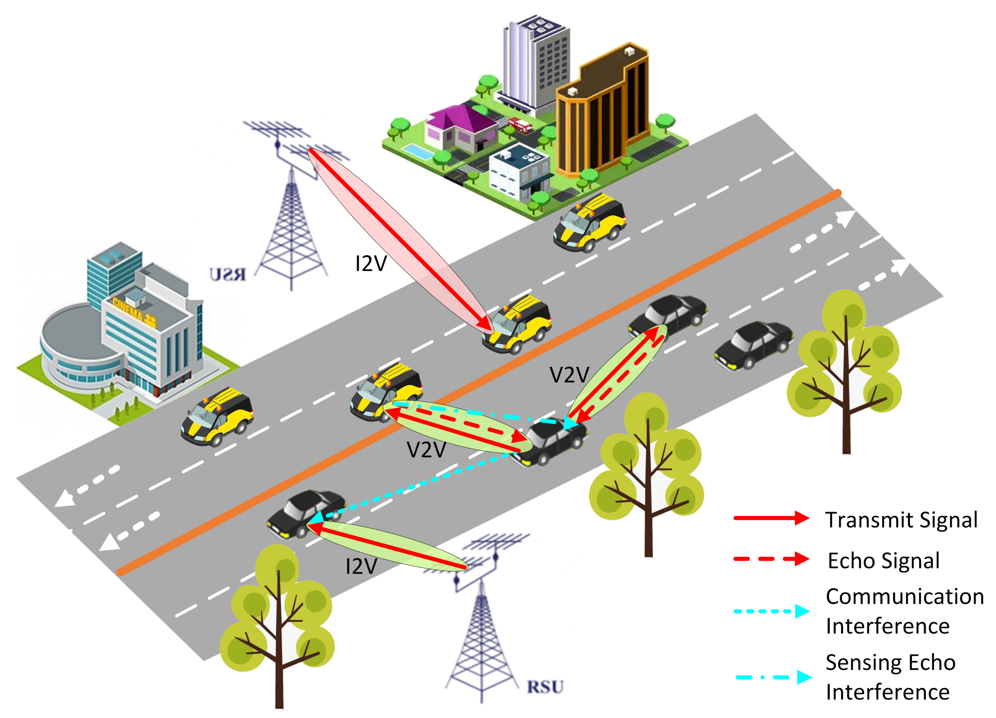
In this paper, we propose a novel algorithm named IMSBA that combines ISAC technology with MAPPO and uses Stackelberg game theory for joint power allocation between I2V and V2V. Specifically, the algorithm first optimizes the beam directions and frequency band allocation for V2V vehicles using MAPPO. Subsequently, in each time slot, it employs a Stackelberg game strategy to jointly optimize the transmission power for I2V and V2V. Additionally, vehicles achieve sensing domain sharing through V2V communication, utilizing sensing information from other vehicles to switch target vehicles and reduce the path loss caused by communication distance or obstruction. For clarity, the contribution of this work is summarized as follows:
To address the challenge of environmental instability, this study employed the multi-agent reinforcement learning algorithm MAPPO to optimize V2V vehicle beam direction and frequency band allocation, reducing interference and enhancing overall sensing–communication performance.
We separated the joint power allocation of I2V and V2V from the reinforcement learning policy and used Stackelberg game theory and iterative optimization to obtain an approximate optimal solution. This method reduces the action space size and improves the learning efficiency of the agents.
V2V communication enables the sharing of sensing domains between vehicles, utilizing the sensing information from other vehicles to switch to closer target vehicles, effectively reducing the path loss caused by communication distance and obstructions.
This paper is structured as follows:
Section 2 introduces the system model,
Section 3 presents the beam allocation algorithm,
Section 4 proposes the simulation results, and
Section 5 concludes the paper.
Notations: A matrix is denoted by a bold uppercase letter (e.g., ), a vector is denoted by a bold lowercase letter (e.g., ), and a scalar is denoted by an ordinary letter (e.g., a). The subscript indicates the index of the vehicle and the time slot (e.g., indicates the beam direction of vehicle k at the nth time slot).
3. Beam Allocation Algorithm Based on MAPPO and Stackelberg Game
3.1. Problem Formulation
The beam direction
of vehicle k is calculated based on the relative change
as follows:
where
represents the beam direction corrected by sensing in the previous time slot;
denotes the angle interval between two adjacent indices in the code book.
indicates the transmit power of each beam for vehicle
k;
represents the frequency band index used by vehicle
k, with each V2V vehicle only able to select one frequency band, while a frequency band can be used by multiple vehicles.
According to the above signal model and the definitions of related variables, the original beam allocation problem can be expressed as follows:
where
represents the total energy efficiency of vehicle
k; for ease of solution, we replace the sensing SINR with
, which represents the total sensing rate of vehicle
k. Constraints (11a) to (11c) are related to transmit power, including the transmit power of each beam and the total transmit power. Constraint (11d) is related to the energy efficiency of vehicle
k. Constraint (11e) is related to the total achievable rate of I2V. Constraint (11f) is related to the sensing rate of vehicle
k. Constraint (11g) specifies the range of the relative change in beam index. Constraint (11h) defines the range of the frequency band index. Constraints (11i) to (11k) specify that a vehicle can select only one frequency band, but a frequency band can be selected by multiple vehicles.
The original beam allocation problem is an MINLP problem, and since it requires the sensing information of target vehicles for assistance, it is also a sequential decision problem. Additionally, beamforming concentrates energy in the specified direction, effectively reducing interference in other directions. Therefore, maximizing overall sensing–communication performance can be approximated by maximizing the individual sensing–communication performance of each vehicle. To simplify the problem-solving process, and considering that the optimization objective is to maximize the energy efficiency, the total I2V reachable efficiency, and the sensing rate of the vehicle, we relax constraints (11d) to (11f) and temporarily disregard their effects.
3.2. Beam Allocation Algorithm Based on MAPPO
V2V reuses the orthogonal frequency bands of I2V, leading to inter-vehicle interference between V2V and I2V. Additionally, V2V supports multi-beam multi-target communication, resulting in inter-beam interference. To mitigate the impact of interference, the beam direction and frequency band allocation for V2V are crucial. These factors not only affect the sensing–communication performance of the current V2V link but also significantly impact the sensing–communication performance of other V2V and I2V links. If V2V vehicles are treated as single agents for decision-making, the reward for the current agent under the same local state–action pair may vary due to the actions of other agents. This environmental instability prevents the agent from proper training.
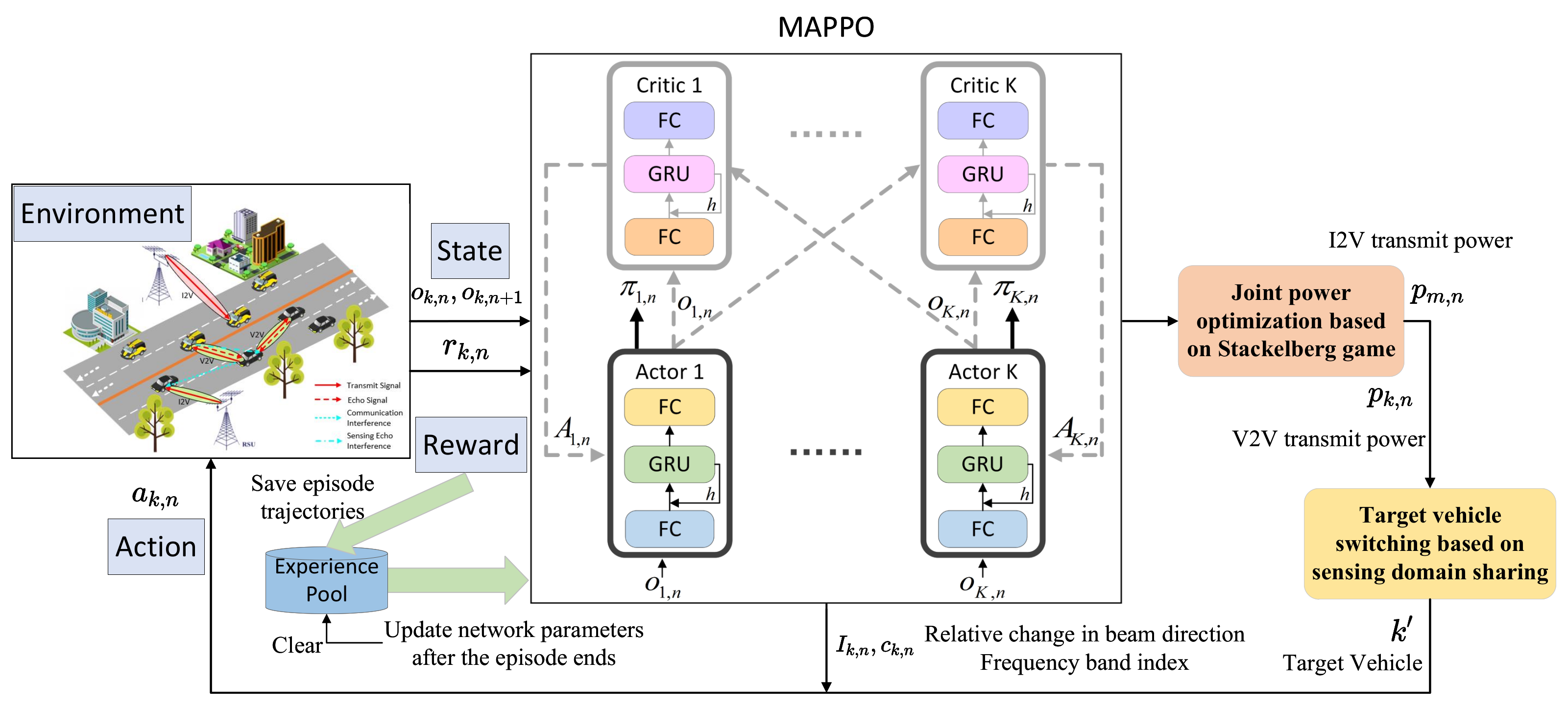
To address the issue of environmental instability, the multi-agent reinforcement learning framework of centralized training and distributed execution has emerged. In this framework, each agent only needs to input its locally observed state into the decision network to make local decisions, saving communication costs between agents. During training, the global state is input into a centralized network for evaluation, guiding the update of the decision network. Considering that the objective function of problem (11) is to maximize overall sensing–communication performance, we adopt the MAPPO algorithm to promote cooperation among agents, achieving better beam direction and frequency band allocation. In the MAPPO algorithm, the actor network serves as the decision network, while the critic network serves as the centralized network. The critic network evaluates the value of the global state to guide the update of the decision network.
For ease of expression, in this chapter, V2V vehicles are also referred to as agents, and their local state can be expressed as
where the local state at time slot
n is composed of the values from time slot
.
represent the position and velocity of vehicle
k, respectively;
represents the sensing information of each beam’s target vehicle, including position, velocity, and direction angle;
denotes the frequency band index selected by vehicle
k;
represents the interference power of vehicle
k on each I2V vehicle
m;
represents the interference power received by vehicle
k for each beam’s downlink communication;
represents the interference power received by vehicle
k for each beam’s echo signal. Since the sensing information includes noise, this decision process is modeled as a POMDP. To improve decision-making, we modify the actor and critic networks to the DRQN network structure, utilizing temporal features from the historical state sequence to compensate for the current state. The global state
, which includes the local states of all agents, can be expressed as
The action of agent
k is denoted as
.
represents the relative change in each beam direction, and
represents the frequency band index selected in the current time slot. Regarding the reward, to promote cooperation, all agents receive the same reward, representing the overall reward of the environment. Therefore, the reward function should be the objective function in problem (11):
where
represent the weights of each part of the reward. By adjusting these weights, resources can be biased towards a specific target.
To facilitate the training of the GRU in the network, at the end of each episode, the trajectory of this episode is saved to the experience pool. Each time step in the trajectory is saved as a tuple
, which is the set of local states of all agents at the current time slot
n;
is the global state at the current time slot
n;
is the set of actions of all agents at the current time slot
n;
is the set of local states of all agents at the next time slot
;
is the global state at the next time slot
;
is the set of rewards of all agents at the current time slot
n, where each element is equal to
. Since MAPPO is an on-policy algorithm, when the number of episodes in the experience pool equals the batch size
, training is performed, and the experience pool is cleared after training. The loss function for the actor network is calculated as follows:
where
represents the network parameters of the actor network;
denotes the proximal policy optimization loss, which stabilizes training results by clipping the update magnitude through the clip strategy [
36]. The proximal policy optimization loss is defined as follows:
where
represents the ratio of the probability of taking action
under the current policy
in local state
to the probability of taking the same action under the old policy
, used to measure the update magnitude of the policy;
represents the advantage function, used to measure the value of the current global state
relative to the average level
;
is the network parameter of the critic network. The value of the global state can be understood as the expected future return starting from the current global state. The purpose of clipping is to limit the update magnitude of the policy to avoid the instability caused by large updates.
represents the entropy of the policy, where a higher entropy indicates a more uniform probability distribution of actions and stronger exploration ability. The loss function for the critic network is calculated as follows:
where
represents the value function of the global state
;
represents the target value function, which is the expected future return, also known as the expected discounted reward, with
as the discount factor. The second term in the function is calculated only when
N is the episode end step.
As shown in
Figure 2, the joint power allocation and target vehicle switching algorithms need to be integrated into the MAPPO framework. The specific implementation details are provided in Algorithms 1 and 2. In summary, the process flow of the beam allocation algorithm based on MAPPO is summarized in Algorithm 3.
| Algorithm 1 Joint Power Allocation Algorithm Based on Stackelberg Game |
Initialize:
;
- 1:
while do - 2:
Fix , calculate (19); - 3:
Initialize ; - 4:
while do - 5:
Fix , solve problem (22), obtain ; - 6:
Update ; - 7:
if then - 8:
- 9:
end if - 10:
According to update , ; - 11:
; - 12:
end while - 13:
if then - 14:
Output: ; - 15:
end if - 16:
; - 17:
end while
|
| Algorithm 2 Target vehicle switching based on sensing domain sharing |
Input: Receiving SNL from other vehicles;
- 1:
for do - 2:
if length() > 1 then - 3:
max_sinr = ; - 4:
idx = −1; - 5:
for to length() do - 6:
if > max_sinr then - 7:
max_sinr = ; - 8:
idx = i; - 9:
end if - 10:
end for - 11:
Retain the sensing information with idx within ; - 12:
end if - 13:
Compute the distance between the current vehicle k and vehicle based on ; - 14:
end for - 15:
min_d = ∞; - 16:
= −1; - 17:
for do - 18:
if < min_d then - 19:
min_d = ; - 20:
= i; - 21:
end if - 22:
end for - 23:
Output: Vehicle as the new target vehicle.
|
| Algorithm 3 ISAC Beam Allocation Scheme Based on MAPPO and Stackelberg Game (IMSBA) |
Initialize:
Initialize actor network parameters ; initialize critic network parameters ; initialize the experience pool ;
- 1:
for episode = 1:MaxEpisode do - 2:
Reset the vehicles’ position and the experience pool; - 3:
Obtain the initial local state ; - 4:
while n ≤ MaxStep-1 do - 5:
Input into the actor network and select action based on the output policy ; - 6:
Execute Algorithm 1 Joint Power Allocation Algorithm. - 7:
Execute Algorithm 2 Target Vehicle Switching Algorithm. - 8:
Observe the next time slot state and calculate the reward (14); - 9:
; - 10:
end while - 11:
if evaluate == False then - 12:
Save the current episode trajectory to the experience pool ; - 13:
if length() == then - 14:
Calculate the advantage function and target value function ; - 15:
Calculate (15); - 16:
Calculate (17); - 17:
Backpropagation and use the Adam optimizer to update ; - 18:
Clear the experience pool ; - 19:
end if - 20:
end if - 21:
end for
|
3.3. Joint Power Allocation Based on Stackelberg Game
In the Internet of Vehicles, resource optimization problems are typically complex and non-convex. Therefore, mathematical methods and tools are crucial for facilitating the solution of these problems. Difference of Convex (DC) approximation is a method that can be used to obtain approximate optimal solutions for complex non-convex problems [
37]. Additionally, methods based on Stackelberg games are considered useful tools for solving complex problems [
38]. In a Stackelberg game, users with different objectives are divided into leaders and followers who cooperate and compete with each other. Based on this strategy, a high-complexity problem can be decomposed into two subproblems of lower complexity. The joint power allocation of I2V and V2V has a high degree of coupling, so we propose a method based on Stackelberg game to transform the joint power allocation problem into two suboptimal power allocation problems, thereby simplifying the solution of the original problem.
In this section, we consider the I2V link as the leader in the game and the V2V link as the follower. For simplicity, this section assumes perfect channel state information is available. The leader aims to maximize the total achievable rate of I2V, while the follower aims to maximize the total energy efficiency and sensing rate of V2V, establishing a competitive relationship between them.
The power allocation problem for the leader can be written as
where
represents the channel gain from the RSU to vehicle
k. Although a larger
increases
, it also causes more severe interference to V2V. Therefore, the first part of the objective function represents the total achievable rate of I2V, i.e., the utility function; the second part of the objective function represents the interference level of I2V to V2V, i.e., the cost function. By observing, it can be found that the objective function is concave with respect to
. Therefore, its partial derivative can be set to zero to obtain
:
where
,
;
represent the channel gains from the RSU and vehicle
k to vehicle
m, respectively. Since the joint power optimization is performed in two stages, the follower’s power, i.e., the V2V transmit power, can be considered constant when solving the leader’s power allocation problem. Similarly, when solving the follower’s power allocation problem, the leader’s power, i.e., the I2V transmit power, can be considered constant. The power allocation problem for the follower can be written as
The first part of the objective function represents the total energy efficiency and sensing rate of V2V, i.e., the utility function; the second part of the objective function represents the interference level of V2V to I2V, i.e., the cost function. Due to the total power constraint, we cannot simply use partial derivatives to obtain the optimal power. Therefore, we can use the CVX toolbox to solve this problem. However, the objective function in the problem is not concave with respect to . Additionally, energy efficiency is a fractional optimization problem, so we need to transform it into a more convenient form for solving.
Firstly, the Dinkelbach algorithm is employed to transform the fractional form of energy efficiency into a linear form of numerator minus
times the denominator. Then, an iterative method is used to solve the problem. The algorithm begins with an initial value
, and in each iteration, the optimal solution
is obtained, which is then used to update
. This iterative process continues until the change in
between two consecutive iterations meets a certain threshold, marking the end of the algorithm. Therefore, based on the Dinkelbach algorithm, problem (20) is transformed into
However, the aforementioned problem is not a concave function with respect to
, necessitating further transformation. For the achievable rate
and sensing rate
, we can decompose them into a log(numerator) minus log(denominator) form, where the first part is concave in
but the second part is not. To address the non-concavity issue, this chapter employs the DC approximation technique to transform the non-concave part into a linear function. Specifically, the non-concave part is linearized using the first-order Taylor expansion, making the linear function both convex and concave. Therefore, problem (21) can be further transformed into
In this context,
represents the first-order Taylor expansion approximation of the non-concave part, where
is the result from the previous iteration and can be considered a constant.
are linear functions of
, representing the interference power during downlink communication and echo sensing, respectively. The algorithm terminates when the outer iteration meets the criterion for
, outputting the joint power allocation for I2V and V2V. Note that the iteration index
i represents the outer iteration, where each outer iteration involves solving the leader and follower problems, while the iteration index
j represents the inner iteration, where each inner iteration involves executing the Dinkelbach algorithm. These iterations form a nested loop structure. Additionally, the optimal solution of this joint power allocation algorithm is deterministic, ensuring the stability of the environment when integrated into a multi-agent reinforcement learning framework.
The CVX toolbox typically uses the interior-point method to solve nonlinear programming problems, so the computational complexity can be expressed as , where represents the number of outer iterations, represents the number of inner iterations, l represents the number of optimization variables, and represents the target accuracy. In summary, the joint power allocation algorithm based on the Stackelberg game proceeds as described in Algorithm 1.
3.4. Target Vehicle Switching Based on Sensing Domain Sharing
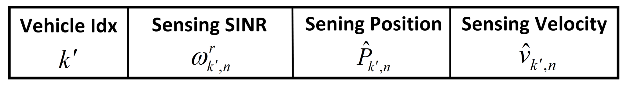
Sensing information can serve as state to guide agent decisions. Additionally, sensing information can be shared among vehicles through V2V communication. Sensing domain sharing extends the sensing range of individual vehicles, aiding in achieving optimized agent decisions and joint power allocation. We introduce a Sensing Neighbor List (SNL) in V2V communication [
39] to facilitate sensing domain sharing among different vehicles during communication. The SNL stores sensing information, with specific details shown in
Figure 3, where
represents the sensing position of the target vehicle,
denotes the sensing velocity of the target vehicle, and
signifies the sensing SINR of the target vehicle’s echo signal, determining the magnitude of sensing noise. During V2V communication, each vehicle broadcasts its own SNL to the target vehicle, which then combines its own sensing information with the SNL and broadcasts it to other vehicles, thereby enabling sensing domain sharing among vehicles. When the target vehicle’s communication distance is too far or its line-of-sight link is obstructed by other vehicles, the SNL can be used to switch to the nearest alternative target vehicle to minimize the impact of path loss on sensing performance.
During the process of sensing domain sharing, there may be cases where the sensing of target vehicles overlaps. In such instances, the SNL may contain multiple entries with vehicle index . To resolve this, sorting based on is performed, retaining only the information corresponding to the highest value of sensing quality. Additionally, due to spectrum conflicts, closer communication distances result in lower path losses but may introduce more severe interference. This issue becomes more pronounced with increasing beamwidth, as larger beamwidths reduce antenna count, weakening the asymptotic orthogonality properties.
In summary, the algorithm for target vehicle switching based on sensing domain sharing is outlined as follows. The computational complexity of this algorithm can be represented as .
4. Simulation Results
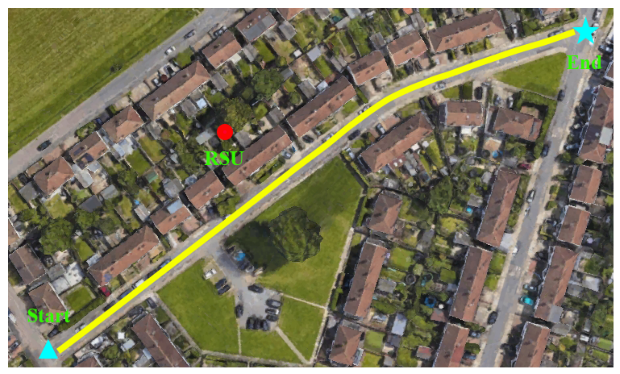
In this section, we validate the effectiveness of the IMSBA algorithm in beam allocation through road vehicle simulation experiments. The real-road trajectory is shown in
Figure 4, with the road’s latitude and longitude coordinates being 51°25′56″ N and 0°03′20″ E. We set the road’s starting point as the coordinate origin
, with
V2V vehicles and
I2V vehicles moving uniformly along the road. The vehicle speed refers to the speed along the road direction.
Table 1 provides other specific simulation parameters.
We compare the proposed IMSBA algorithm with other benchmark algorithms, detailed as follows:
IMSBA w/o switch: This algorithm, based on the proposed IMSBA algorithm, removes the target vehicle switching based on sensing domain sharing. As a result, the direct link is affected by communication distance and obstacles, leading to degraded communication and sensing performance.
IMSBA w/o allocate: This algorithm, based on the proposed IMSBA algorithm, removes the joint power optimization based on the Stackelberg game. Therefore, in this algorithm, the transmit power uses fixed values of 1 W, 10 W, and 20 W.
ISSBA: In this algorithm, the base station uses the DRL algorithm DQN to allocate beams to mobile drones, aiming to maximize data transmission rates [
40]. We apply this algorithm to the scenario in this chapter, replacing the base station with the V2V source vehicle and the mobile drone with the V2V target vehicle. The interaction of actions among multiple agents causes environmental instability, severely reducing the learning efficiency and convergence performance of the agents.
Unless otherwise specified, the vertical axis in the result figures represents the sum of the performance across all time slots in an episode, and the horizontal axis represents training duration. Each unit change on the horizontal axis corresponds to 14,400 time slots or 32 episodes.
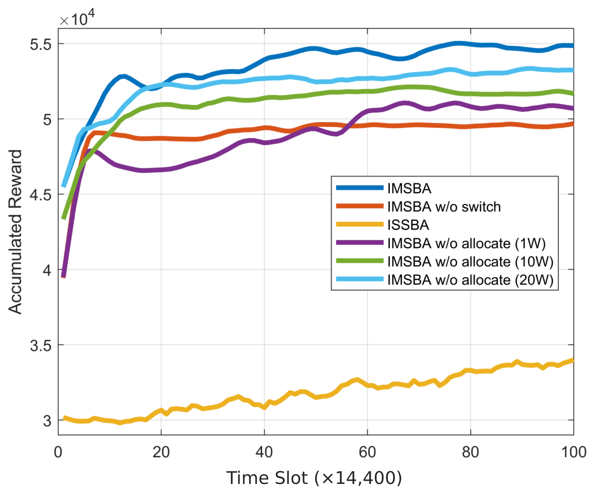
First, we present the cumulative reward curves for the proposed algorithm and other comparison algorithms, as shown in
Figure 5, to validate the effectiveness and convergence of the algorithm. This figure is obtained under the condition of reward weight
and 64 transmit and receive antennas, with similar trends observed under other conditions. The IMSBA algorithm achieves the optimal convergence performance, with an average reward per time slot of 121.8, validating the effectiveness of the proposed algorithm. Due to the instability caused by multi-agent actions, the DQN-based ISSBA algorithm fails to learn effectively, resulting in the worst convergence performance, with an average reward per time slot of 76.2. In related ablation experiments, the IMSBA w/o allocate algorithm, which does not perform joint power allocation and uses fixed power instead, shows inferior convergence performance compared to the IMSBA algorithm. Additionally, the convergence performance of the IMSBA w/o allocate algorithm improves with increasing transmit power, primarily because a higher transmit power enhances V2V sensing performance and I2V communication performance, outweighing the decrease in V2V energy efficiency. The IMSBA w/o switch algorithm, which does not switch target vehicles, suffers from link blockage or excessive communication distance, resulting in lower convergence performance compared to the IMSBA algorithm. It is noteworthy that the convergence performance of the IMSBA w/o switch algorithm is also lower than that of the IMSBA w/o allocate algorithm, indicating that the performance gain from switching target vehicles is greater than that from joint power allocation.
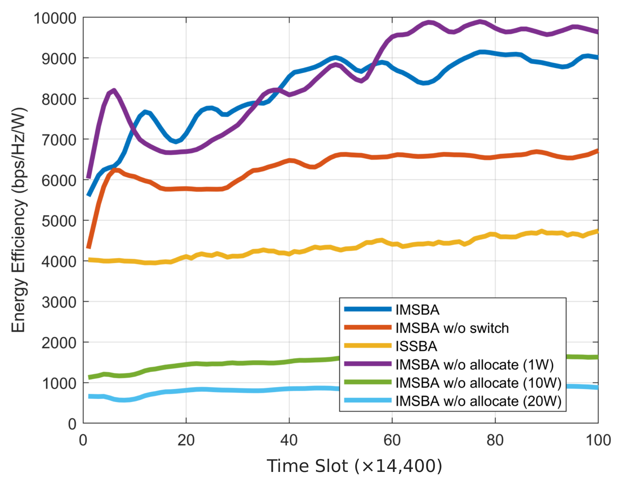
We present individual curves for the components of cumulative reward shown in
Figure 5 and compare them with other benchmark algorithms. The energy efficiency change curve is depicted in
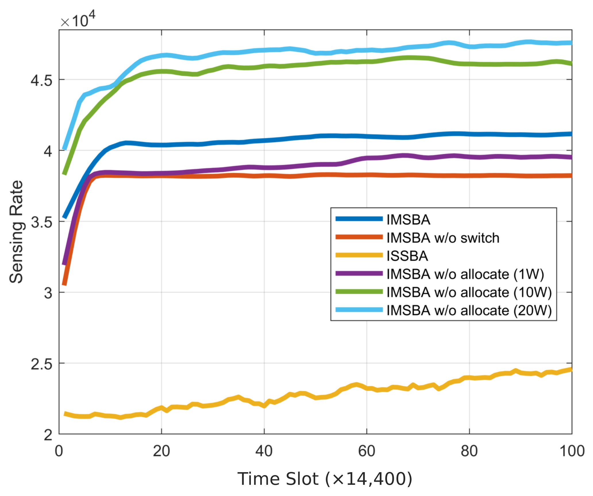
Figure 6. Due to IMSBA w/o allocate fixing the transmission power at 1 W, this algorithm achieves the highest energy efficiency, which is 8.1% higher compared to the IMSBA algorithm. IMSBA w/o switch experiences significant path loss due to not switching target vehicles, resulting in a 30% lower energy efficiency compared to the IMSBA algorithm. The ISSBA algorithm exhibits a lower energy efficiency than IMSBA due to environmental instability, yet it still outperforms the IMSBA w/o allocate algorithms with fixed transmission powers of 10 W and 20 W. The sensing performance change curve is shown in
Figure 7. Unlike the energy efficiency curve, the IMSBA w/o allocate algorithms with fixed transmission powers of 10 W and 20 W achieve a higher sensing performance, consistent with the findings in
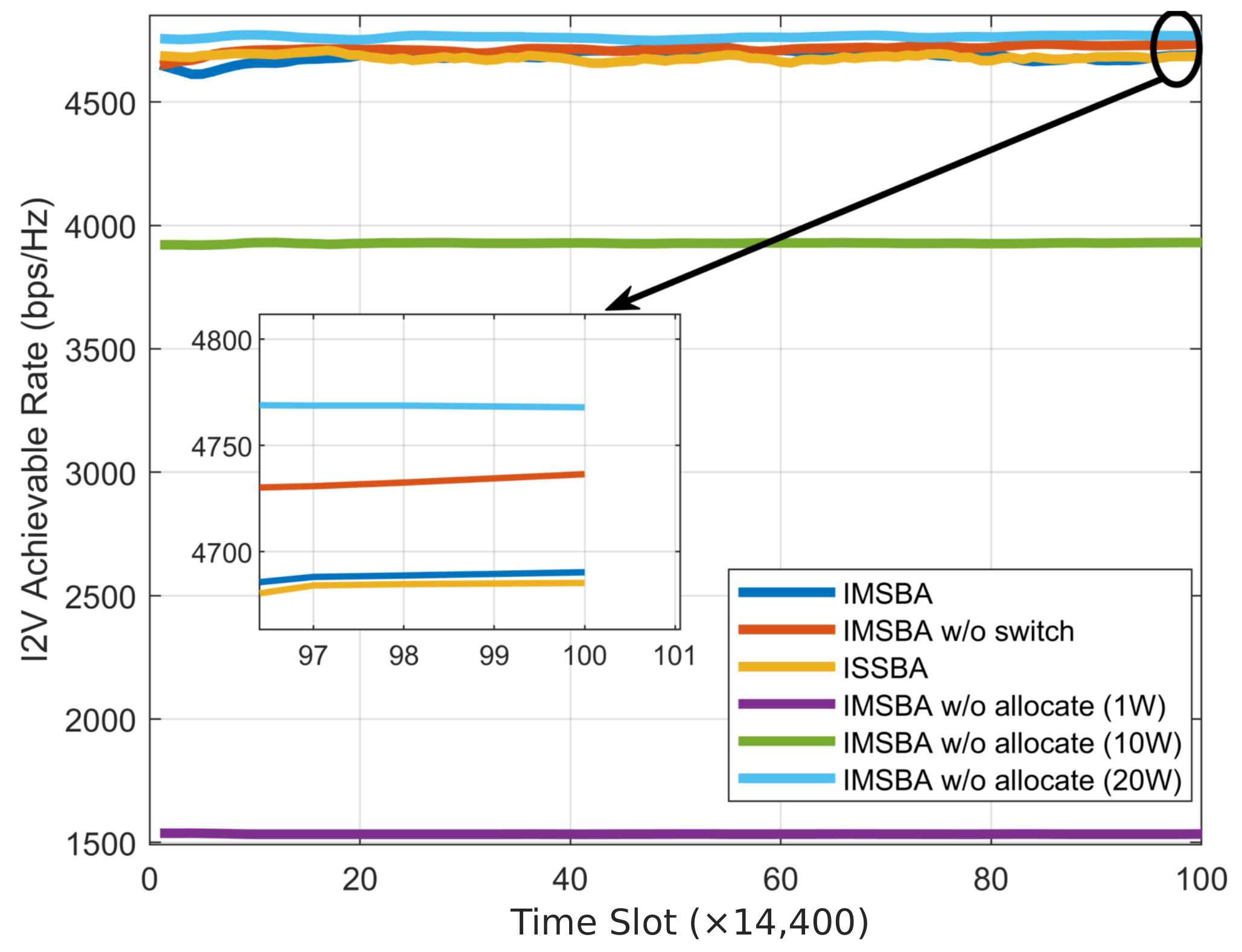
Figure 5. Notably, even with a fixed transmission power of 1 W, the IMSBA w/o allocate algorithm achieves a higher sensing performance than the IMSBA w/o switch algorithm, confirming that switching target vehicles leads to greater performance improvements than joint power allocation. The I2V achievable rate change curve is depicted in
Figure 8. Clearly, as the I2V transmission power increases, the total achievable rate also increases, consistent with the results of the IMSBA w/o allocate algorithm. The IMSBA algorithm considers I2V interference in joint power allocation, hence reducing I2V transmission power, resulting in slightly lower I2V achievable rates compared to the IMSBA w/o switch algorithm. Moreover, due to a reduced path loss from switching target vehicles, the IMSBA algorithm under current reward weights tends to allocate more resources to V2V, thus resulting in slightly lower I2V achievable rates compared to the IMSBA w/o switch algorithm.
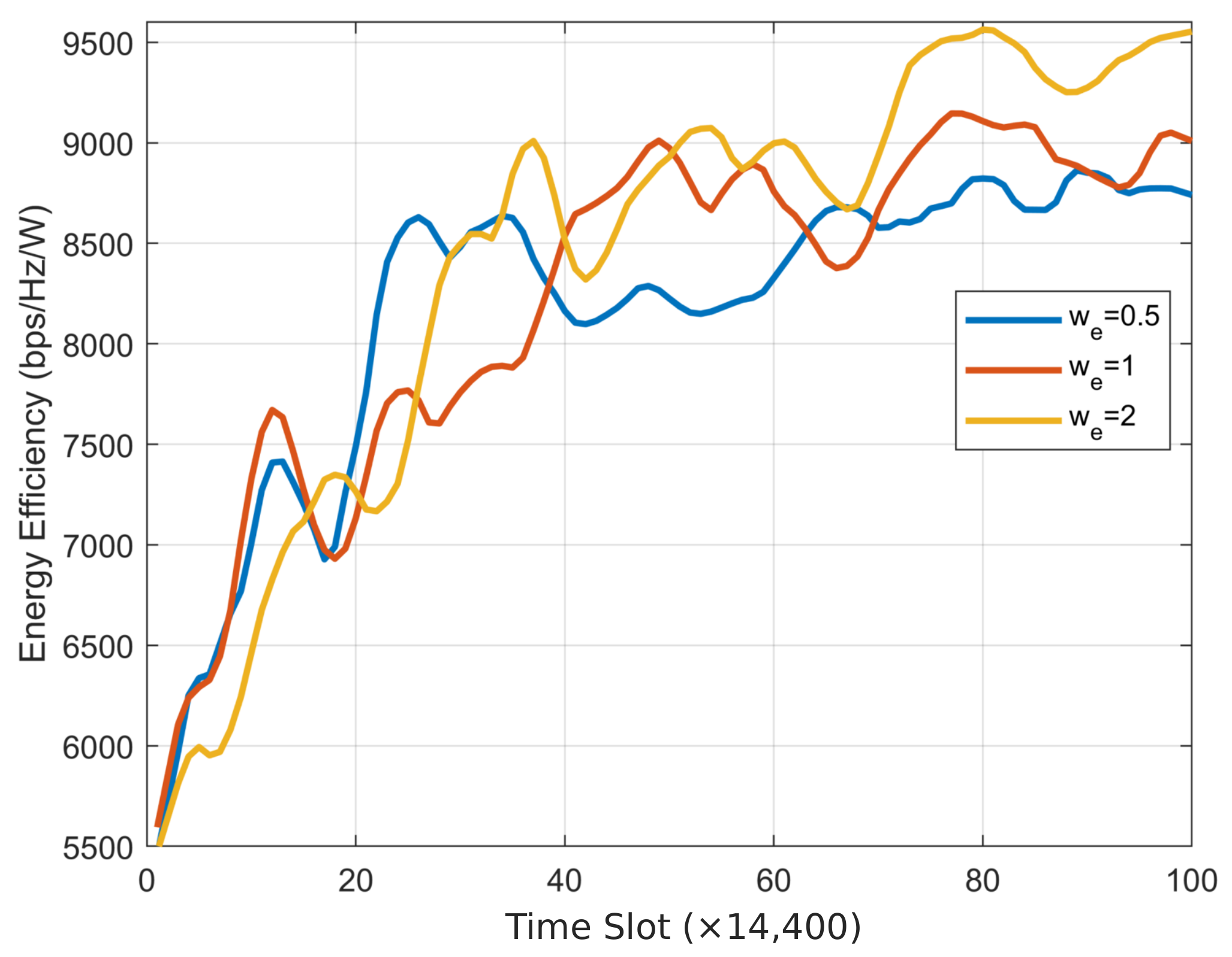
The weights of various components in the MAPPO reward function influence the final convergence performance. Therefore, we adjusted the weights to observe their impact on the results. The three figures above were obtained with 64 transceiver antennas, and when one weight was changed, the other weights were set to 1. The curve of energy efficiency versus weight
is shown in
Figure 9. Clearly, by increasing
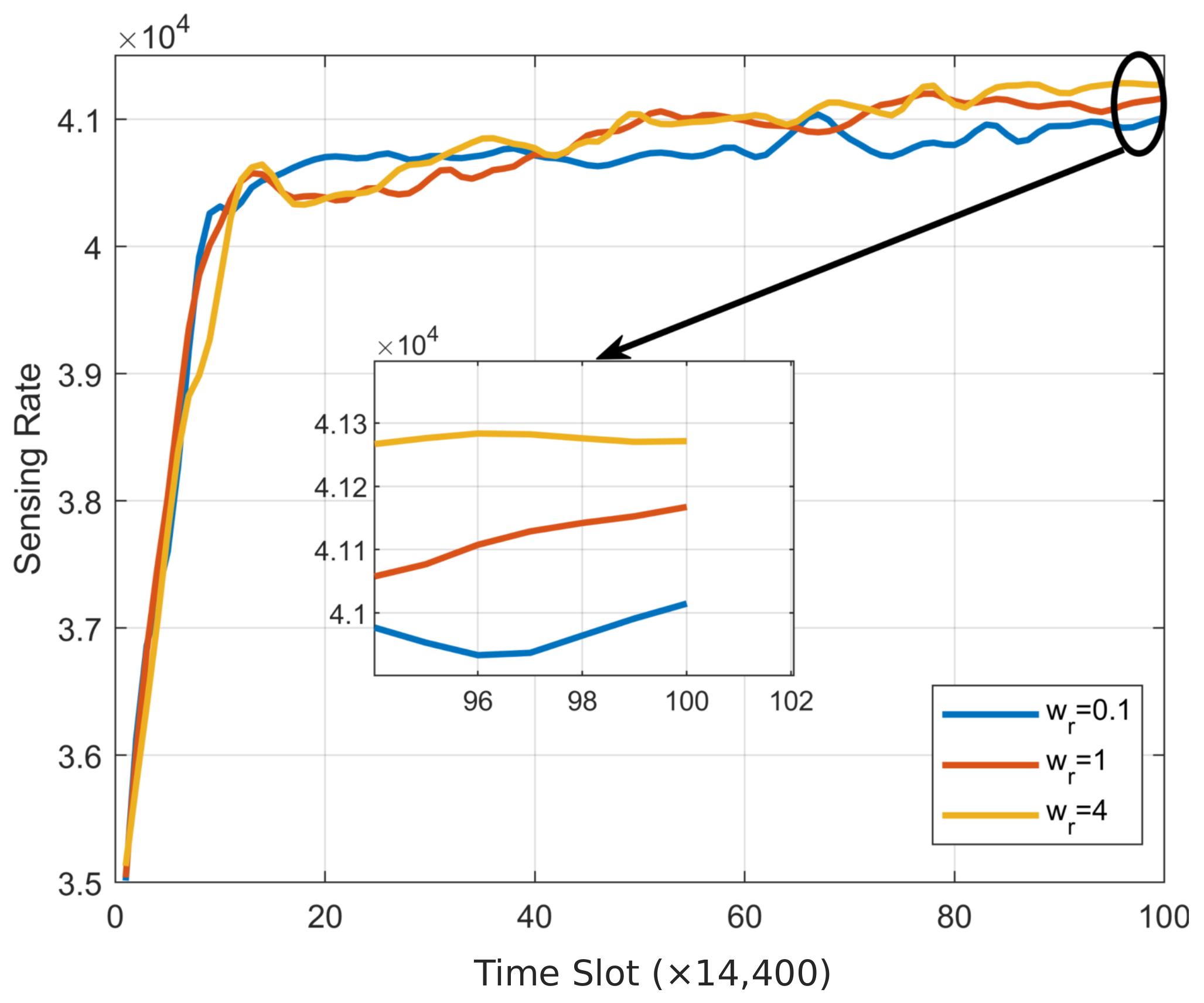
, resources are tilted towards energy efficiency, resulting in an upward trend in energy efficiency. The curve of sensing performance versus weight
is shown in
Figure 10. Similar to energy efficiency, as
increases, sensing performance also improves. Notably, sensing performance has a crucial impact on the overall performance of the IMSBA algorithm. Poor sensing performance leads to inaccurate target sensing results, which, in turn, affects the agent’s action selection. Therefore, when adjusting the weight
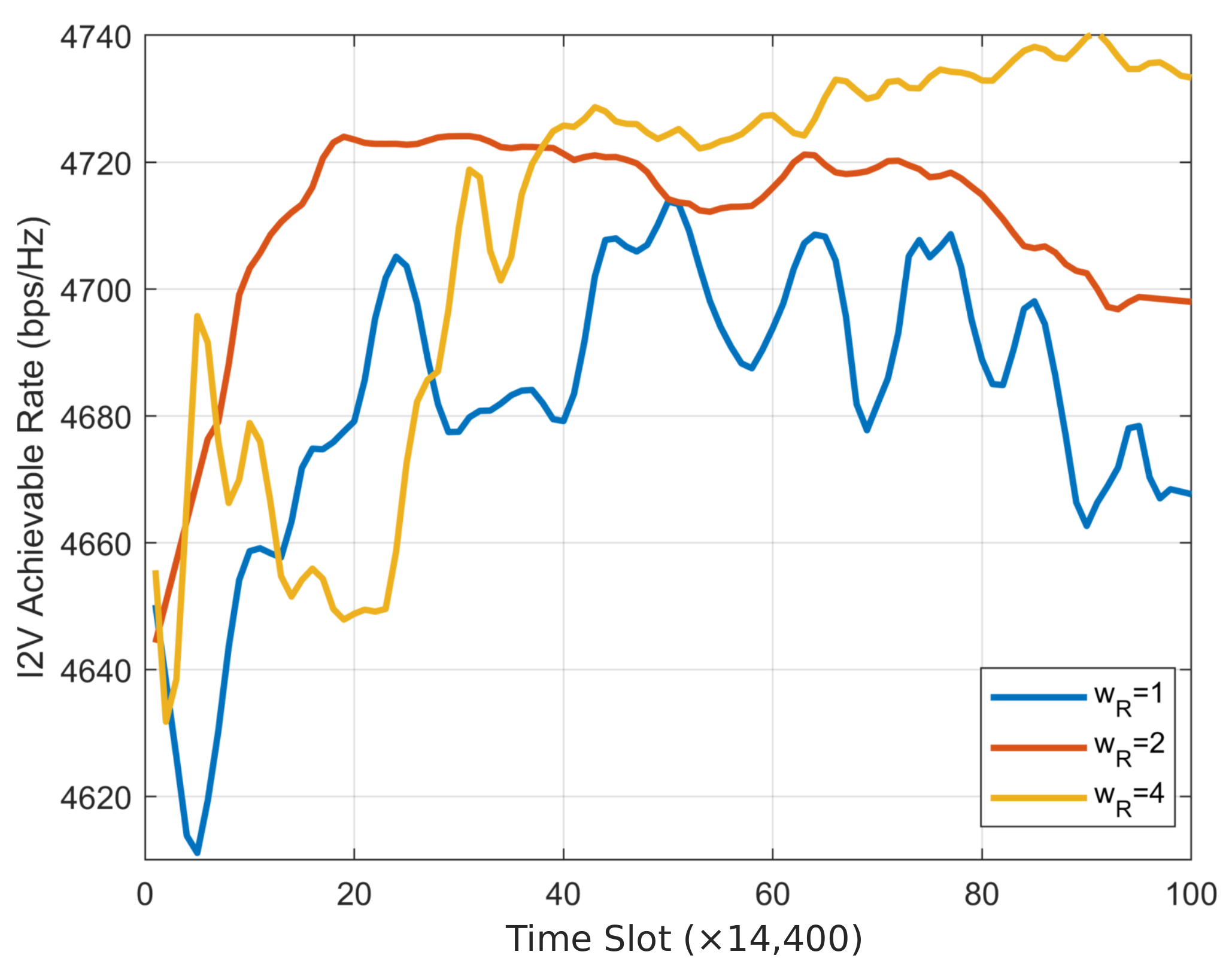
, the change in sensing performance is not very significant and needs to be maintained at a high level. The curve of the sum rate of I2V versus weight
is shown in
Figure 11. Firstly, the trend still increases with
. Secondly, due to the relatively small variation in the sum rate, when
is small, resources are inclined towards V2V, resulting in a downward trend in the I2V sum rate in the later stages. This downward trend gradually weakens as
increases.
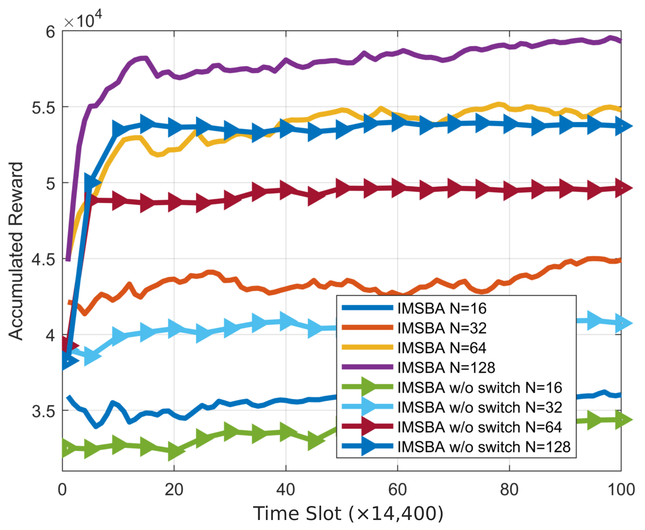
Figure 12 shows the variation of cumulative reward with the number of antennas for the IMSBA algorithm and the IMSBA w/o switch algorithm, with all experiments using a reward weight of 1. It can be observed that the cumulative reward for both algorithms increases with the number of antennas due to the larger antenna array gain, which enhances overall sensing and communication performance. Under the same number of antennas, the cumulative reward for the IMSBA w/o switch algorithm is lower than that of the IMSBA algorithm due to the higher path loss. Moreover, the gap in cumulative rewards between the two algorithms widens as the number of antennas increases. This is because, with fewer antennas, the beam width is wider, and the smaller path loss exacerbates inter-vehicle interference, leading to a reduction in the cumulative reward of the IMSBA algorithm.
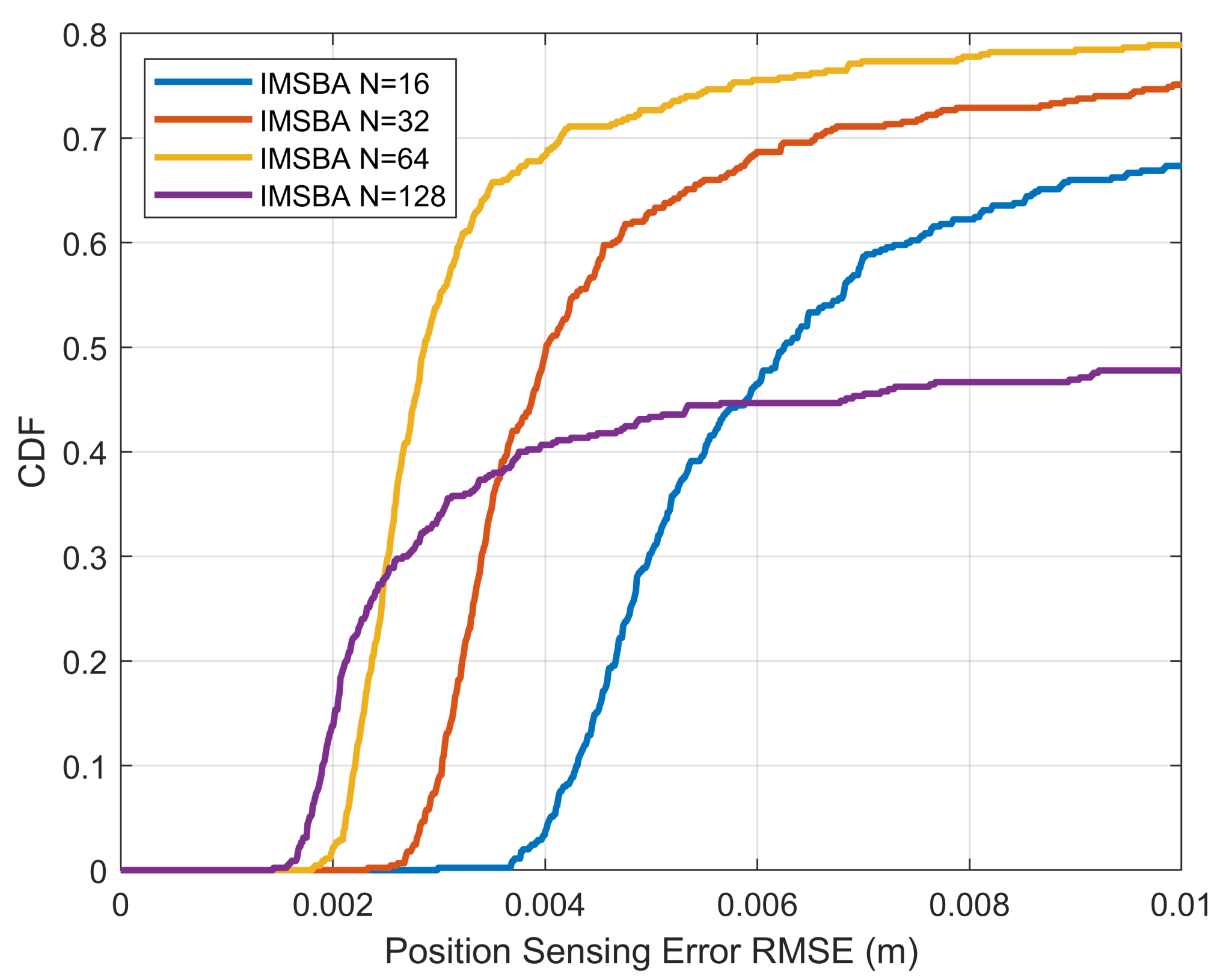
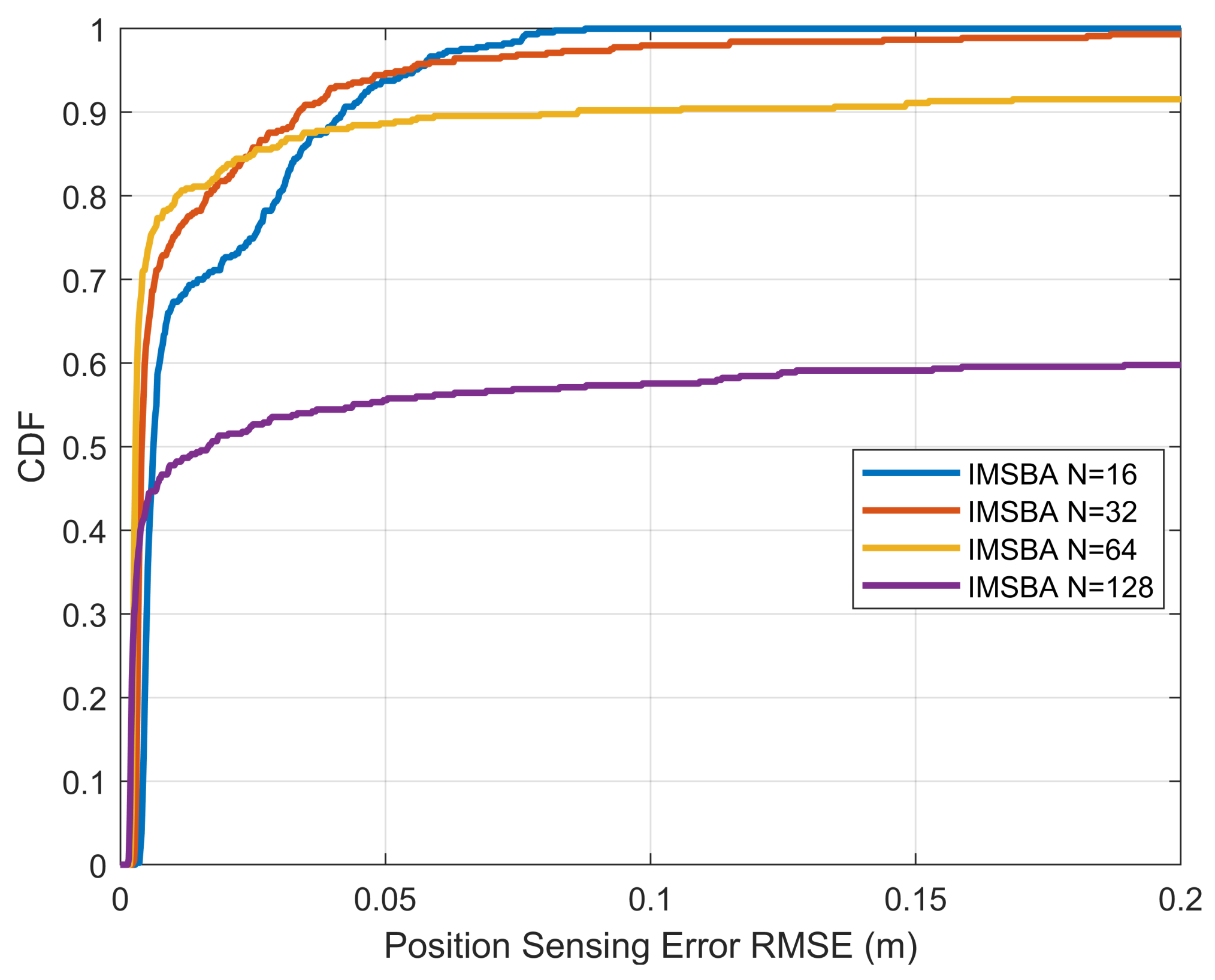
To further assess the sensing performance,
Figure 13 plots the CDF of position sensing error versus the number of antennas, with all algorithms using a reward weight of 1. This error refers to the root mean square error (RMSE) between the true position and the sensed estimated position. In
Figure 13, the horizontal axis range is smaller, while in
Figure 14, the horizontal axis range is larger. It can be seen that for smaller position sensing errors, more antennas result in a higher CDF. For example, when the number of antennas is 128, the probability of the position sensing error being less than
m is 28%, which is higher than other antenna numbers. However, for larger position sensing errors, fewer antennas result in a higher CDF. This is because the IMSBA algorithm requires target vehicle switching, which can lead to beam misalignment after switching. With more antennas, the beam width is narrower, and beam gain drops more significantly when misaligned, leading to larger position sensing errors, as shown in
Figure 14. In the stable condition without target vehicle switching, more antennas result in greater antenna array gain and smaller position sensing errors, as shown in
Figure 13.
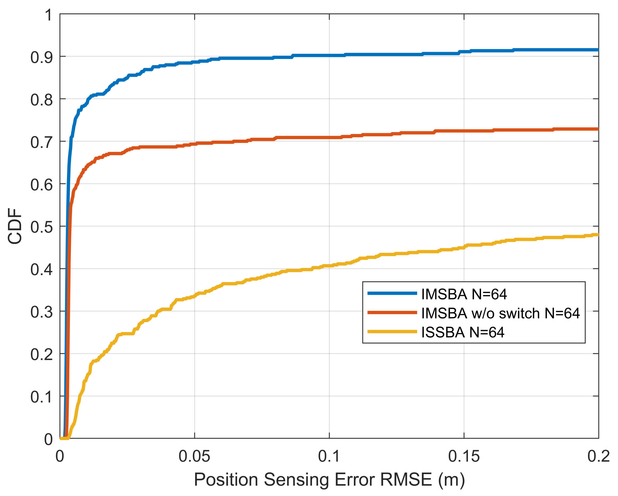
Figure 15 compares the CDF of the position sensing error for the proposed IMSBA algorithm with other benchmark algorithms, with all algorithms using a reward weight of 1 and 64 antennas. It can be seen that, regardless of the error magnitude, the IMSBA algorithm achieves the highest CDF, with a probability of 91.6% for the position sensing error being less than 0.2 m. The IMSBA w/o switch algorithm, constrained by a higher path loss, results in larger position sensing errors. In the ISSBA algorithm, multi-agent actions cause environmental instability, preventing effective training, leading to the largest position sensing error.
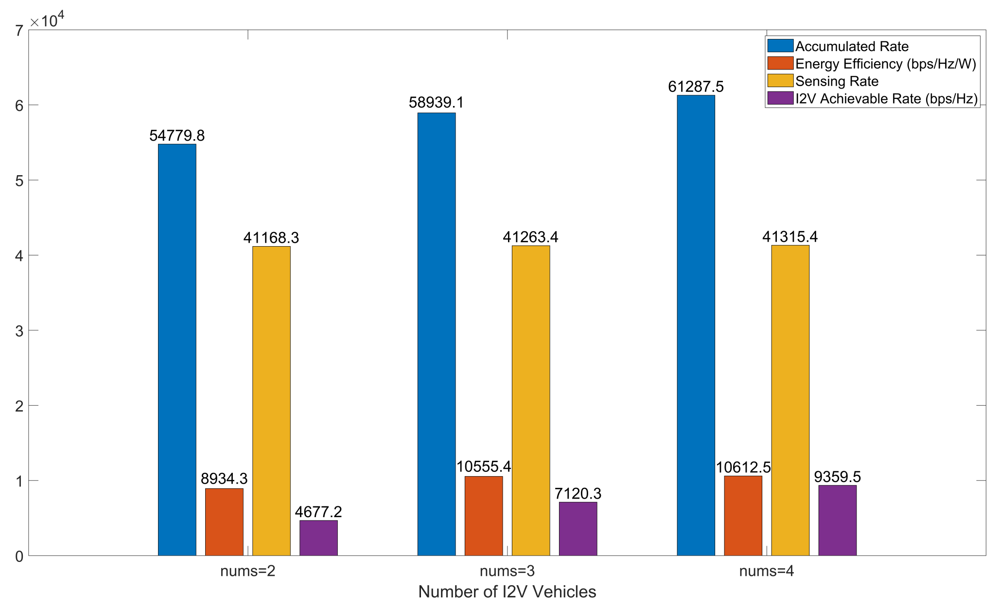
Figure 16 illustrates the performance comparison of the IMSBA algorithm under different numbers of I2V vehicles, using experimental conditions with a reward weight of 1 and 64 transmit–receive antennas. The values in the figure represent results after algorithm convergence. As established earlier, I2V employs orthogonal frequency bands for communication, with the number of I2V vehicles equating to the number of orthogonal frequency bands available. Consequently, as the number of I2V vehicles increases, V2V can reuse more orthogonal frequency bands, further reducing mutual interference between V2V pairs and between I2V and V2V. As shown in
Figure 16, the overall cumulative reward increases with the number of I2V vehicles, with V2V’s energy efficiency, sensing performance, and I2V’s achievable rates following the same trend as cumulative reward.
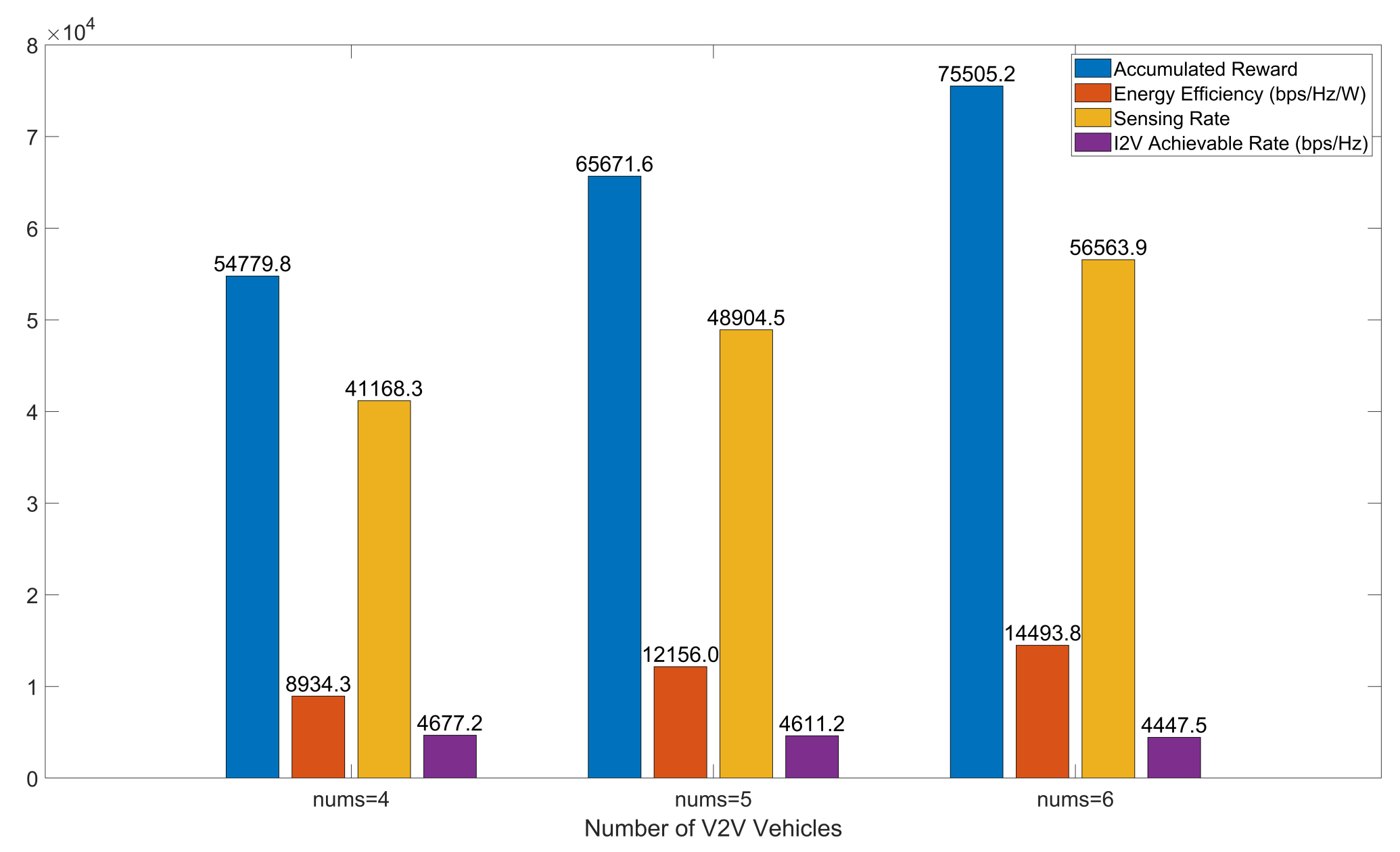
Figure 17 presents the performance comparison of the IMSBA algorithm under different numbers of V2V vehicles, similarly using experimental conditions with a reward weight of 1 and 64 transmit–receive antennas. The values in the figure represent results after algorithm convergence. As the number of V2V vehicles increases, the cumulative reward shows an upward trend. However, increased V2V vehicles exacerbate inter-vehicle interference, resulting in a certain degree of reduction in I2V total achievable rates. Moreover, due to increased inter-vehicle interference, the growth rate of cumulative reward exhibits a declining trend; the cumulative reward growth at six vehicles is 9.7% lower compared to five vehicles.
IMSBA is expected to improve the communication robustness and sensing accuracy of ISAC systems in 6G scenarios by jointly optimizing beam direction, spectrum, and power allocation through multi-intelligent body reinforcement learning and a Stackelberg game. Meanwhile, the V2V sensing sharing and target switching mechanism expands the sensing range of the vehicle. The IMSBA architecture has good modularization characteristics, which makes it easy to be deployed on edge computing platforms. Although it still needs to be validated under real-road conditions, this scheme has shown the potential to become the foundational framework for intelligent beam management in future ISAC systems.


