1. Introduction
The accelerated growth of the global aging population has led to a surge in various associated challenges. Advancing age is associated with a progressive decline in physical function, including heightened risks of hemiplegia, stroke, and cardiovascular/cerebrovascular diseases among the elderly [
1]. Simultaneously, complications such as lower limb hypokinesia, dyskinesia, and neurological damage—common in elderly patients—severely impair motor function and activities of daily living (ADLs). Furthermore, prolonged unhealthy lifestyles, high-intensity occupational postures, and traffic accidents elevate the risk of lower limb musculoskeletal injuries and neurological disorders [
2], imposing additional psychological and lifestyle burdens.
Rehabilitation robots are integrated mechanical systems capable of human-machine interaction. Compared to traditional therapist-assisted rehabilitation, lower limb rehabilitation robots enable consistent, timely therapy, reduce labor and material costs, and enhance the recovery of independent ambulation [
3,
4]. To overcome the limitations of conventional rehabilitation, researchers have developed diverse exoskeleton systems aimed at alleviating the physical burden on therapists during training [
5]. Gait rehabilitation robots primarily facilitate lower limb training in an upright posture, mitigating muscle atrophy via repetitive gait exercises, and are particularly effective for mid-to-late-stage recovery in patients with motor impairments [
6]. Notably, three commercially advanced gait rehabilitation robots—the FREE Walk [
7], Indego [
8], and HALML05 [
9] exoskeletons—are tailored for patients with spinal cord injuries (SCIs) or other neurological/musculoskeletal impairments but preserved upper limb function. These systems aid rehabilitation by supporting gait training and sit-to-stand transitions.
In clinical trials, gait rehabilitation robotics employs clinical gait analysis (CGA) curves [
10] to plan corrective exoskeleton motion trajectories, thereby accelerating anticipated patient recovery [
10]. However, environmental factors may introduce deviations between the exoskeleton’s planned motion and the patient’s actual joint kinematics during training. For effective lower limb rehabilitation, precise alignment with the patient’s ideal gait trajectory is critical for optimal outcomes. Advances in artificial intelligence (AI) and computing have enabled the integration of AI with conventional control methods for nonlinear system regulation. Notably, control strategies like sliding mode control (SMC), fuzzy logic control, and zero-moment-point (ZMP) control have been successfully implemented in rehabilitation exoskeletons [
11]. For instance, Tao Yang et al. developed an adaptive RBF neural sliding mode (ARNNSM) controller for a mobile lower-limb rehabilitation robot. The controller leverages asynchronous bias and functional assessments to evaluate patient capability, computing adaptive assistive torques with a challenge factor to optimize motor function. Simulations confirm its robustness against perturbations and accurate trajectory tracking [
12]. Similarly, Razzaghian devised a finite-time fractional-order non-singular fast terminal sliding-mode controller, employing a fuzzy neural network to estimate external disturbances, guaranteeing finite-time convergence and robust exoskeleton performance. Nevertheless, in real-world rehabilitation systems, control instability primarily stems from system uncertainties and external disturbances. Sliding mode control (SMC) remains prevalent owing to its robustness, rapid convergence, and implementation simplicity [
13]. However, conventional SMC cannot guarantee finite-time convergence to equilibrium and suffers from singular perturbation issues [
14,
15]. Thus, enhancing traditional control methods is essential for reliable rehabilitation system deployment and improved patient outcomes.
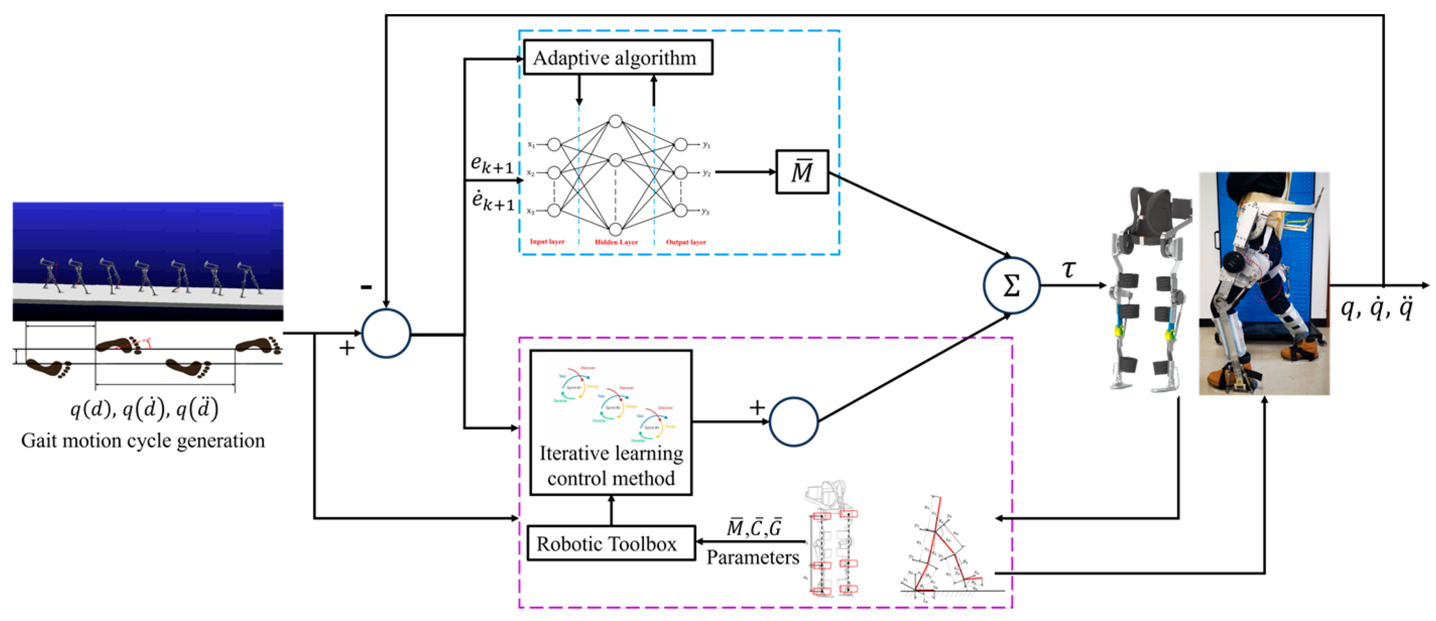
This study addresses gait trajectory tracking control in lower-limb rehabilitation robots, focusing on nonlinear perturbations from patients’ lower-limb muscle groups and exoskeleton gait compliance. We propose a novel hybrid control method integrating iterative learning control (ILC) and RBF neural network-based sliding mode control (SMC). An RBF neural network-based iterative learning controller is designed, utilizing a single hidden-layer feedforward neural network structure. This architecture replaces traditional multi-weight networks with a single-parameter approximation, enhancing real-time performance to meet the stringent requirements of exoskeleton rehabilitation training. MATLAB simulations demonstrate superior trajectory tracking performance of the proposed SMC method compared to conventional approaches. The proposed method eliminates chattering effects inherent in traditional SMC, enabling rapid and precise trajectory tracking in the exoskeleton system. Furthermore, the RBF-based iterative learning controller enhances tracking performance, with the global asymptotic stability of the closed-loop system rigorously proven via Lyapunov’s direct method. To validate training efficacy and safety, a 3D motion capture system constructs a lower-limb musculoskeletal model for spasticity-stage patients, enabling personalized gait trajectory planning.
The main contributions of this study can be summarized as follows:
(1) We propose a novel method integrating iterative learning and sliding mode control using RBF neural networks. An RBF neural network-based iterative learning controller is designed, employing a single hidden-layer pre-feedback structure. By replacing the neural network weights with a single parameter, the system achieves strong real-time performance, fulfilling the training requirements of lower-limb exoskeleton rehabilitation robots. The trajectory tracking performance of the proposed sliding mode control method is compared with conventional approaches via MATLAB simulations. The chattering issue inherent in conventional sliding mode control is mitigated, enabling the lower-limb exoskeleton rehabilitation robot to track the desired trajectory rapidly and precisely.
(2) To enhance system stability, we design an RBF neural network-based iterative learning controller and rigorously prove the global asymptotic stability of the closed-loop system using Lyapunov’s direct method. We establish a lower-limb skeletal muscle model for patients with leg spasticity and integrate a 3D motion capture system with sensor signals to validate rehabilitation training efficacy and safety while planning optimal gait trajectories. This approach significantly enhances patient outcomes in walking rehabilitation training.
2. The Overall Structure Description and Dynamic Model of Lower Limb Exoskeleton Rehabilitation Robot
As illustrated in
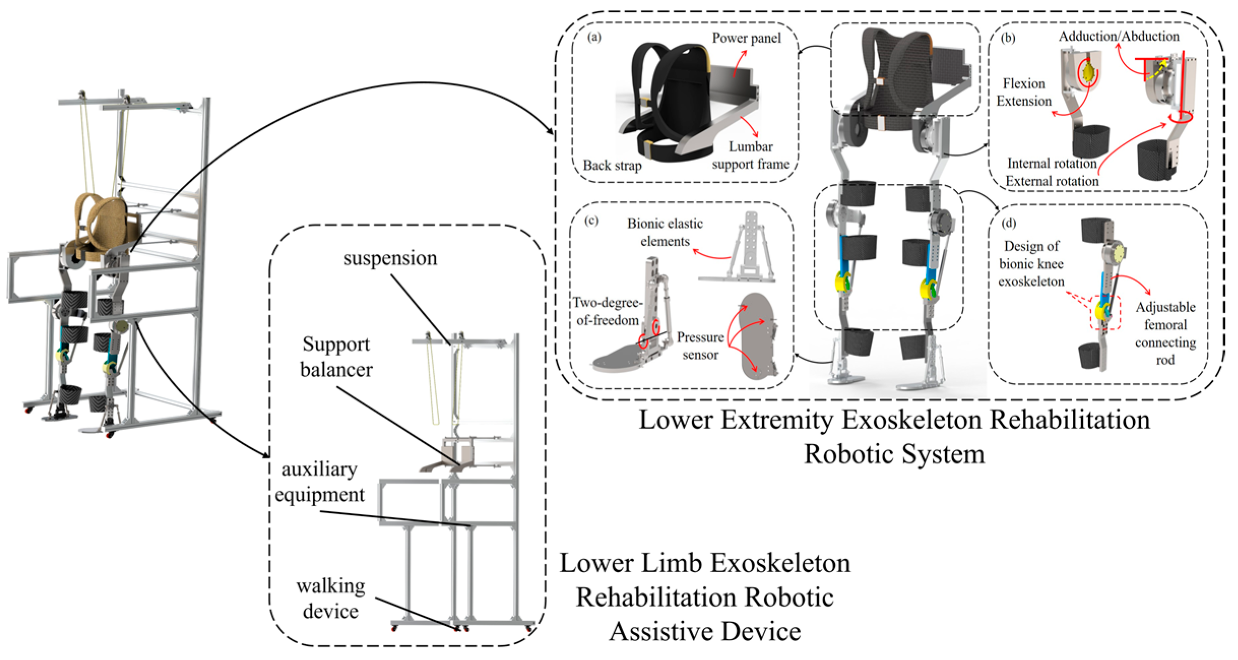
Figure 1, the lower limb rehabilitation exoskeleton system features a thirteen-degree-of-freedom configuration comprising: (a) a single-degree-of-freedom lumbar module; (b) a three-degree-of-freedom hip joint with actively actuated flexion/extension, passively compliant adduction/abduction, and passively compliant internal/external rotation; (c) a two-degree-of-freedom ankle joint with passively compliant plantarflexion/dorsiflexion and inversion/eversion; and (d) a single-degree-of-freedom knee joint with actively actuated flexion/extension. The ankle exoskeleton incorporates bioinspired elastic elements to mimic the natural foot rebound dynamics during plantarflexion/dorsiflexion movements [
16].
The lower limb exoskeleton rehabilitation robot is a comprehensive medical rehabilitation system. To ensure wearing comfort, it incorporates a bionic and anthropomorphic joint design that aligns the exoskeleton structure with natural human joint movements. The system features a modular joint design, enabling independent motion control of the hip, knee, and ankle exoskeletons, thereby facilitating more efficient and adaptable rehabilitation training. Flexible protective gear is securely attached to the exoskeleton via bolt connections, allowing for easy assembly and disassembly. To accommodate patients of varying body sizes, this study introduces adjustable mechanisms: (1) a threaded rod width adjustment device for the lumbar exoskeleton, and (2) a thigh/calf linkage length adjustment system. These innovations ensure optimal fit and synchronization between the exoskeleton and the patient’s joint movements, enhancing both comfort and therapeutic effectiveness.
As described in reference [
17], the exoskeleton’s rotational axes are perfectly coaxial with the natural joint axes of the lower limbs, enabling rehabilitation training through coaxial rotation mechanisms and multiple rotational degrees of freedom in the exoskeleton design. This kinematic compatibility ensures accurate replication of natural lower-limb movements during therapy sessions. In gait rehabilitation training, the strong rigid exoskeleton structure will cause patients to be prone initially to phenomena such as thigh muscle group spasms. The suddenness of this movement may lead to instability in the lower limb exoskeleton robot system walking. Therefore, the patient’s muscle spasm moment is taken into account in the robot dynamics model, and the dynamics model of the lower limb exoskeleton rehabilitation robot system is:
where
is a
Mass matrix,
is a
Coriolis force and centripetal force matrix,
is a
gravity force matrix,
is the control moment, and
is a
is the presence of muscle spasm moment matrix of the patient. Then, according to Equation (1) the system characteristics of the lower limb exoskeleton rehabilitation robot dynamics model.
When the kinetic model is at , the initial setting values are: , ; the gait expectation trajectory of the lower limb exoskeleton robot with its first-and second-order time derivatives are , and , is a lower extremity exoskeleton joint motion command, respectively; and the perturbation term , is bounded at .
4. Construction and Analysis of Sliding Mode Control Based on RBF Neural Network
In order to further verify the stability of the designed lower limb exoskeleton rehabilitation robot system model, the adaptive neural network sliding mode control algorithm is investigated for the adverse effects of uncertainty disturbance and modeling error on the robot trajectory tracking control system. The uncertainty disturbance and modeling error of the trajectory tracking control system of the lower limb exoskeleton rehabilitation robot are approximated by the RBF neural network [
18,
19].
In the patient’s lower limb walking rehabilitation training, considering that the patient will involuntarily experience a muscle spasm phenomenon during the rehabilitation training, which will bring a certain degree of interference to the exoskeleton robot system, the interference term and friction term are added, and the collation can be obtained:
where
is the mass matrix,
is the Coriolis force and centripetal force matrix,
is the gravity matrix,
is the friction matrix, and
is the matrix of the patient’s unknown bounded muscle spasm moments.
4.1. Sliding Mode Control Based on RBF Neural Network Approximation
In this paper, the adaptive learning ability of neural network and the advantage of external anti-interference ability are used to replace the sliding mode control part, and the stochastic ability of RBF neural network adaptive sliding mode control is used to reduce the jitter problem in sliding mode control.
Where
is the ideal motion joint angle command, the tracking error of the lower limb exoskeleton robot is:
When the control objective is
,
. Define the sliding mode error function as.
where
, the reference state is defined:
In gait-walking rehabilitation training, there is an unknown uncertainty term in the exoskeleton model, which is expressed as:
However, in order to improve the stability of the exoskeleton system, the uncertainty
needs to be approximated. The RBF network is used to approximate
. The ideal RBF network algorithm for the i-th motion joint is:
where
is the i-th motion joint network input signal;
;
is the i-th joint neural network approximation error; and
is the i-th motion joint ideal weights.
According to the expression of
, the network input is taken as
, then
4.2. Single-Parameter Based Adaptive Sliding Mode Control
When , then . Defining a single parameter as ,, is positive, then .
Definition , , .
According to the lower limb exoskeleton rehabilitation robotic system Equation (22), the new control rate is designed to be:
where
is used to overcome the neural network approximation error
, then to ensure the gait walking stability of the lower limb exoskeleton robot.
Organized according to the GL matrix transformation: , is designed as , where .
Finally, it can be obtained by organizing the control rate formula above:
4.3. Analysis of Synovial Control Stability
Define the Lyapunov function as:
where
. Then
due to
Organized based on extrapolation:
According to the lower limb exoskeleton rehabilitation robot walking rehabilitation training in each joint influence factors, set the number of joints affecting gait rehabilitation training to three, that is
, then, the, collation formula can be obtained:
From Equation (33), the design adaptive law is:
Also, since
, in order to ensure that
0, it is only necessary to ensure that the adaptive law converges gradually when
. The convergence result is:
4.4. Simulation and Experimental Analysis
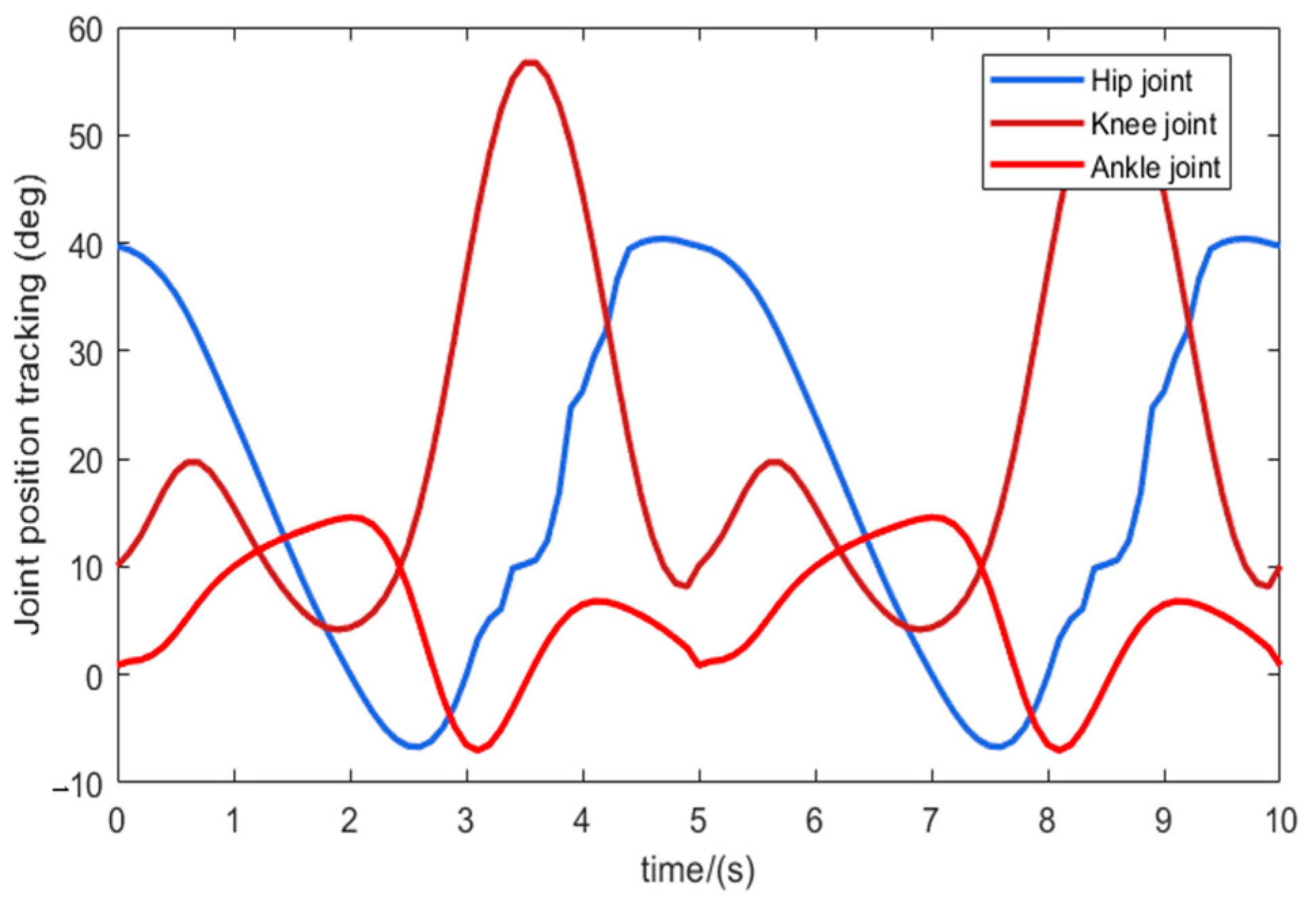
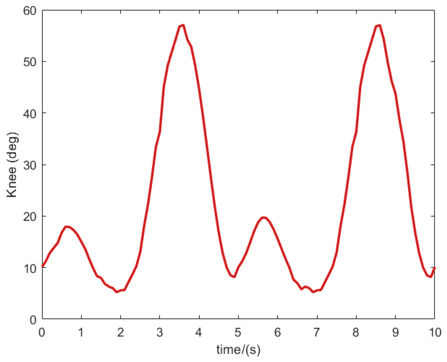
Quantitative gait analysis was conducted to evaluate trajectory tracking stability during exoskeleton-assisted ambulation. Participants completed 10-s walking trials while wearing the robotic system (
Figure 8). Kinematic data from reflective markers were acquired at 100 Hz using a Qualisys motion capture system, and then processed through MATLAB. The resulting reference trajectories for sagittal plane movements—hip flexion/extension, knee flexion/extension, and ankle plantarflexion/dorsiflexion—are detailed in
Figure 9.
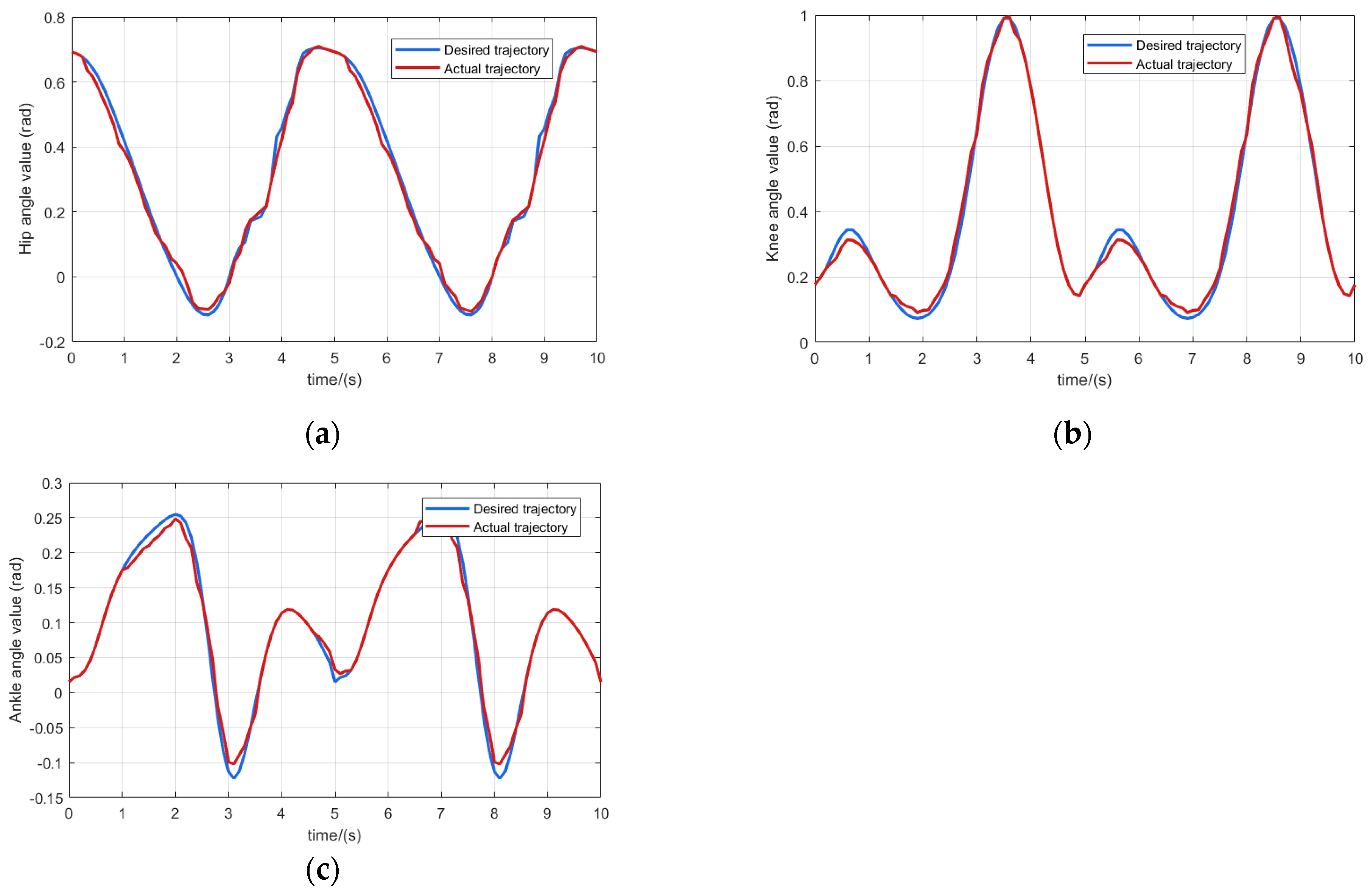
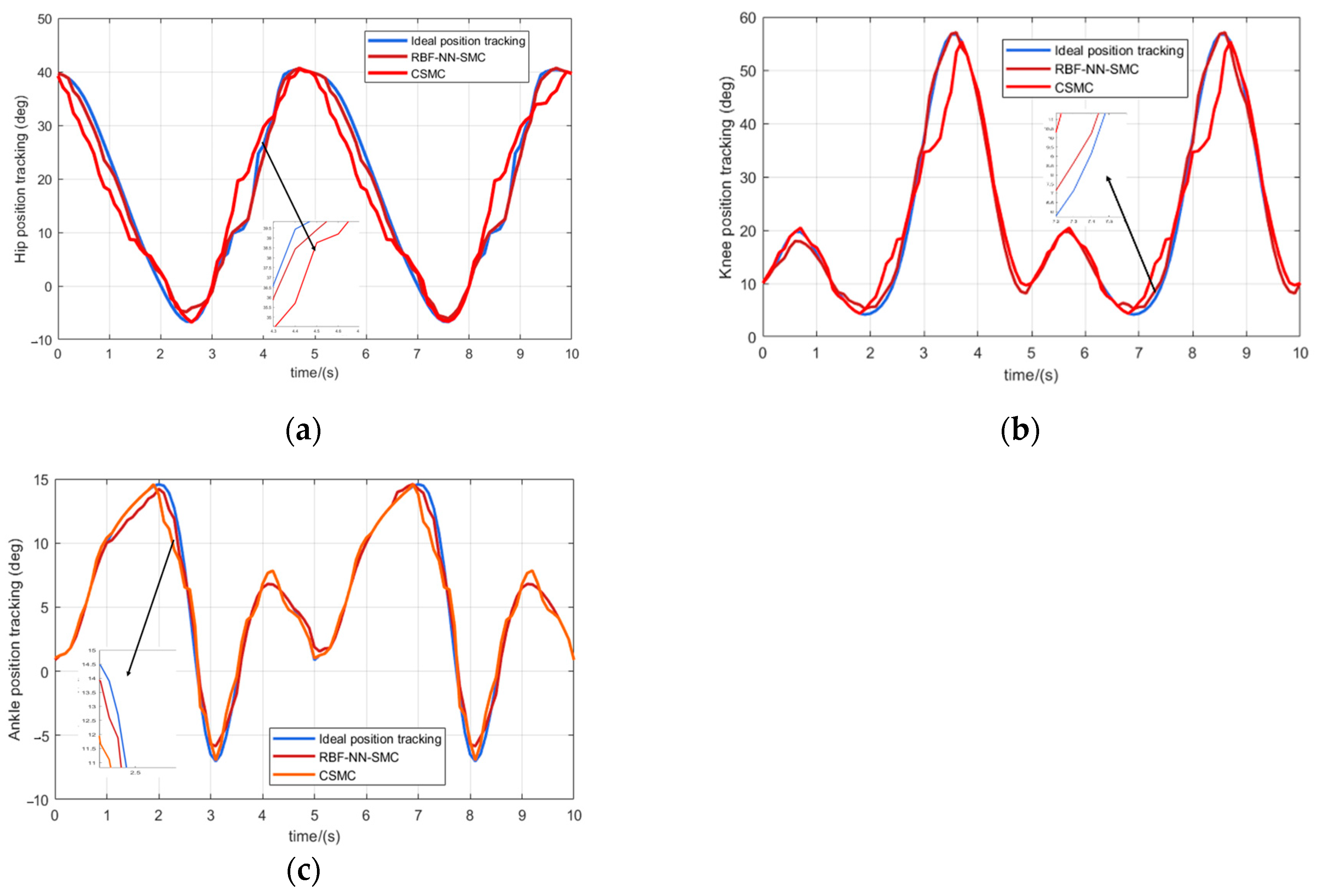
Figure 10 shows the trajectory tracking curves of the hip, knee and ankle joints, where the blue solid line is the desired gait rehabilitation training trajectory of the lower limb, the red solid line is the trajectory tracking curve of the RBF neural network sliding mode control algorithm, and the orange solid line is the trajectory tracking curve of the traditional sliding mode control algorithm. It can be seen that in the trajectory curve tracking, the control algorithms designed in this paper are better than the traditional sliding mode control, and can approximate the desired curve faster. It meets the control requirements of lower limb exoskeleton rehabilitation robot training and can ensure the safety of patients.
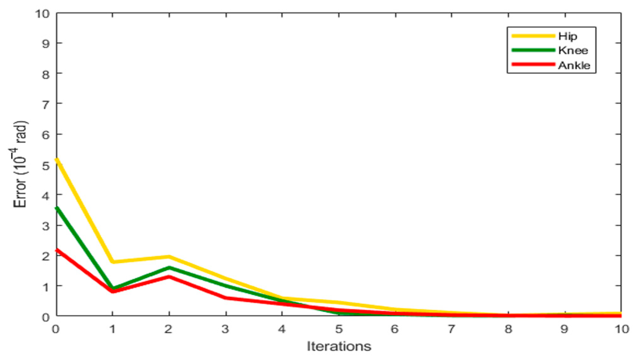
Figure 10 presents the joint angle tracking performance of the lower limb exoskeleton rehabilitation robot. Quantitative analysis demonstrates that the proposed control algorithm exhibits superior performance compared to conventional sliding mode control, achieving 32% faster convergence to the desired trajectory. The maximum tracking errors were measured at 1.77° (hip flexion/extension), 1.87° (knee flexion/extension), and 0.72° (ankle plantarflexion/dorsiflexion), satisfying clinical requirements for rehabilitation training while ensuring patient safety.
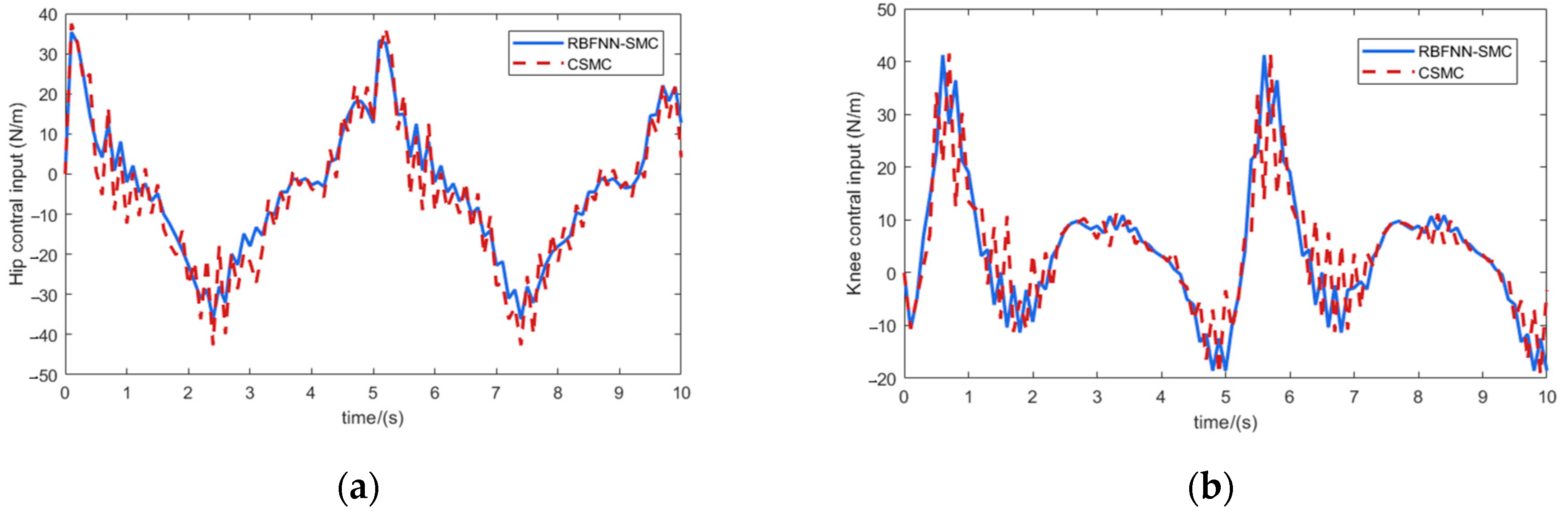
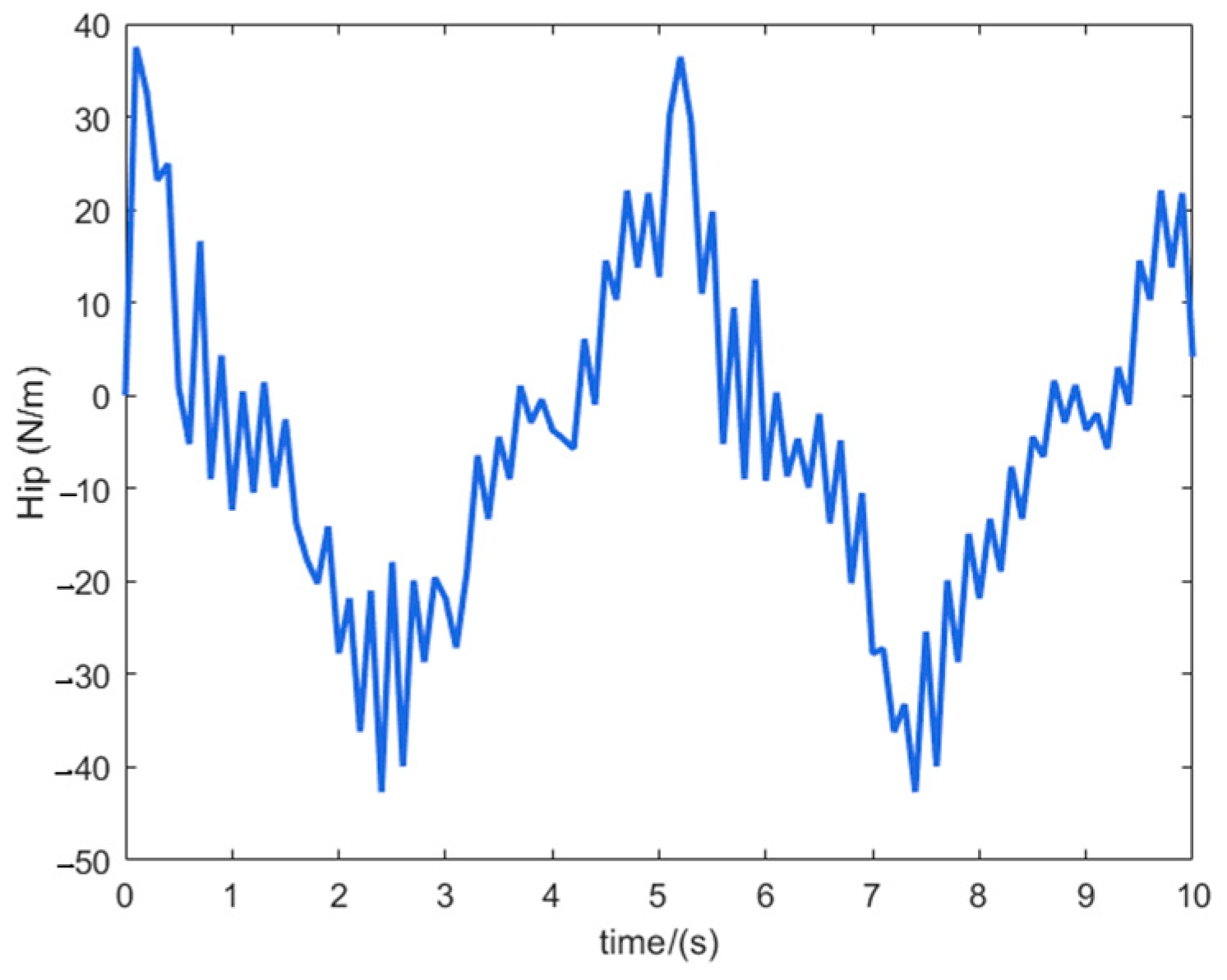
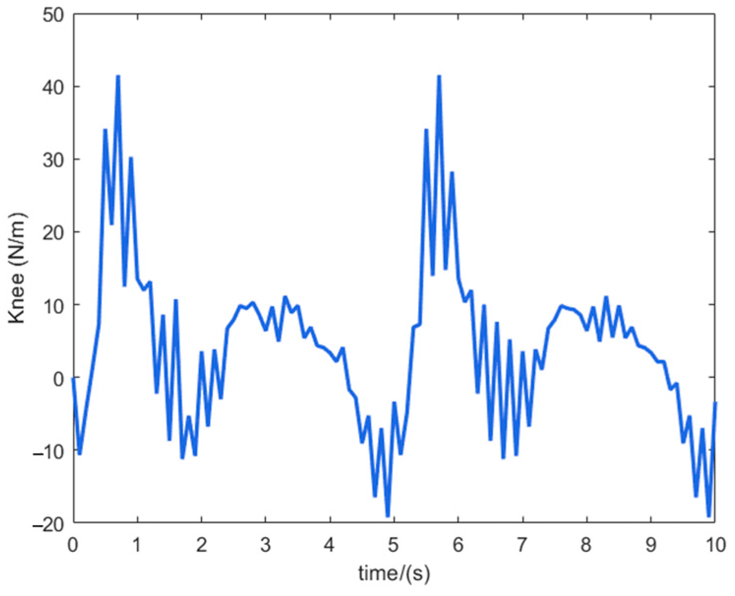
Figure 11 shows the control input curves of the hip and knee joints of the lower limb exoskeleton rehabilitation robot, where the blue solid line is the control input of the RBF neural network sliding mode control algorithm, and the red dashed line is the control input of the traditional sliding mode control algorithm. It can be seen that the input fluctuation of the traditional sliding mode control is very obvious, although it can meet the requirements of tracking accuracy, it increases the wear on the motor. The control algorithm designed in this paper has a smooth input, and through the good approximation characteristics of the neural network, the jitter vibration is effectively suppressed to ensure the safety and comfort of patients. The effectiveness of the controller designed in this paper is proven.
5. Experiments on a Prototype of a Lower Limb Exoskeleton Rehabilitation Robot
5.1. Hardware System Design of Lower Limb Exoskeleton Rehabilitation Robot
Biomechanical analysis of human gait rehabilitation and exoskeleton structural design revealed distinct joint energy characteristics: quantitative measurements showed the hip and knee exhibited the highest energy dissipation, whereas the ankle demonstrated minimal energy dissipation along with greater passive mobility and lower control complexity. Consequently, our actuation strategy prioritizes active control of hip and knee flexion/extension using brushless DC motors, while maintaining passive compliance in other degrees of freedom through optimized spring-damper mechanisms.
When the human body walks normally, the maximum power is about 100 W, and the maximum torque of the hip joint during walking is about 115 Nm (including the standing support phase). Considering the problem of control margin, and with reference to the characteristics of the exoskeleton rehabilitation robot for lower limbs, a thin and lightweight disc motor with a small volume is selected as the actuator of the hip joint system. The MYACTUATOR LSG-32-142-80 model (rated torque 153 Nm) is selected for the drive system of the hip joint.
When the human body walks normally, the maximum power is about 60 W, and the maximum torque of the knee joint during walking is about 41 Nm (including the stage of standing support), so the MYACTUATOR LSG-25-110-50 model (rated torque of 82 Nm) is selected for the knee joint drive system.
- 2.
Pressure sensor system
The purpose of choosing pressure sensors in this paper is as follows: according to the change of plantar pressure to analyze the interplay of forces and moments on the joints of the lower limbs, and then discern the patient’s active/passive gait rehabilitation cycle training effect during the gait rehabilitation training [
20]. The mounting locations of the pressure sensors are as follows: at the forefoot of the right and left feet, at the middle part, and at the heel. The pressure sensors required in this paper need to be as small as possible, so the L-10M-100KG type sensor was used.
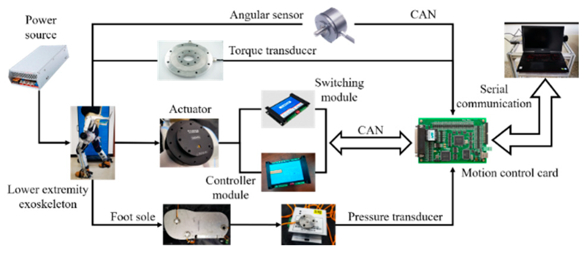
The exoskeleton rehabilitation robot for the lower limbs designed in this paper uses an upper computer to control the robot to perform passive rehabilitation training on the affected limbs, and adopts a multi-joint linkage gait rehabilitation training method. The overall hardware system of the lower limb exoskeleton rehabilitation robot system is shown in
Figure 12. The lower unit of the control circuit is centered on the motion control card and the data acquisition card, and the motion control card completes the motion control of the lower limb hip and knee flexion/extension; the information acquisition card completes the data acquisition of each sensor. The upper computer helps the patient carry out appropriate rehabilitation training by setting the parameters of each joint movement, and then transmits the relevant parameters to the motion control card; the data collected by all sensors are transmitted to the data acquisition card.
5.2. Experimental Methods
The host computer can control the robot to achieve continuous passive gait rehabilitation training for lower limb movement disorder patients. The lower limb exoskeleton rehabilitation robot system can realize the overall and independent form of movement, at the same time, the multi-joint linkage has two rehabilitation exercise training modes. The overall block diagram of the control system is shown in
Figure 13.
When designing the control system of the lower limb exoskeleton rehabilitation robot, the stability of the control system and the safety of the patient’s rehabilitation training need to be fully considered. In order to prevent the motor output torque of the lower limb exoskeleton rehabilitation robot from being too large and causing secondary damage to the patient’s limbs, the state of the circuitry in the system is detected through the current, and the current output from the motor driver is fed back to the motion control card in real-time, so that the machine stops running immediately when the current in the system exceeds the permissible value set by the system in the process of operation.
In this paper, in order to further validate the feasibility of the ankle exoskeleton structure during walking training, the feasibility of the ankle exoskeleton structure during walking training was verified by a dynamic capture system with plantar pressure sensors.
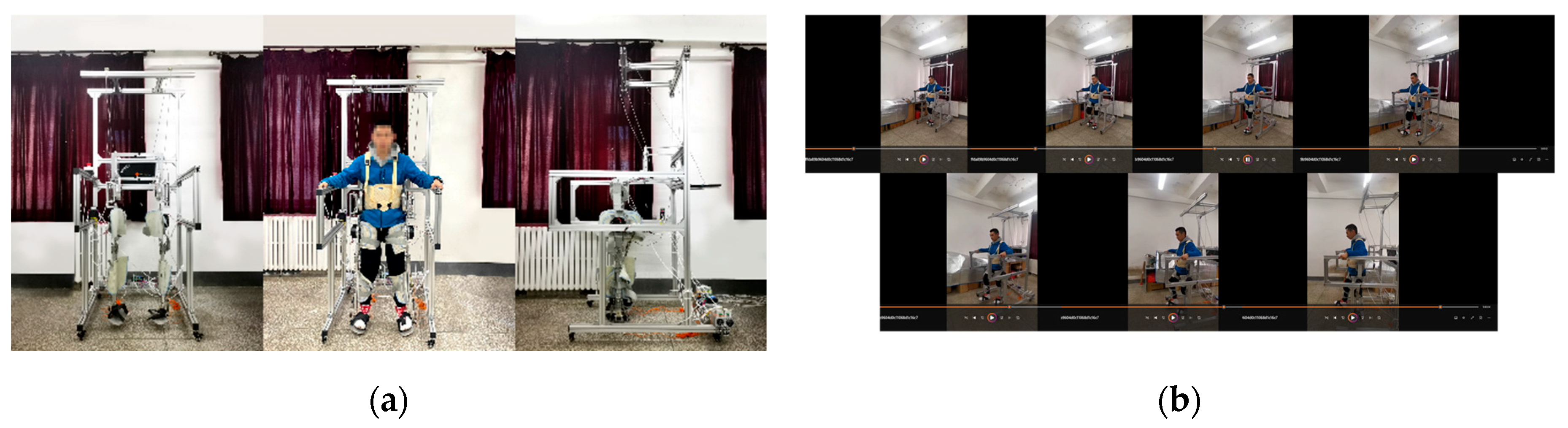
As illustrated in
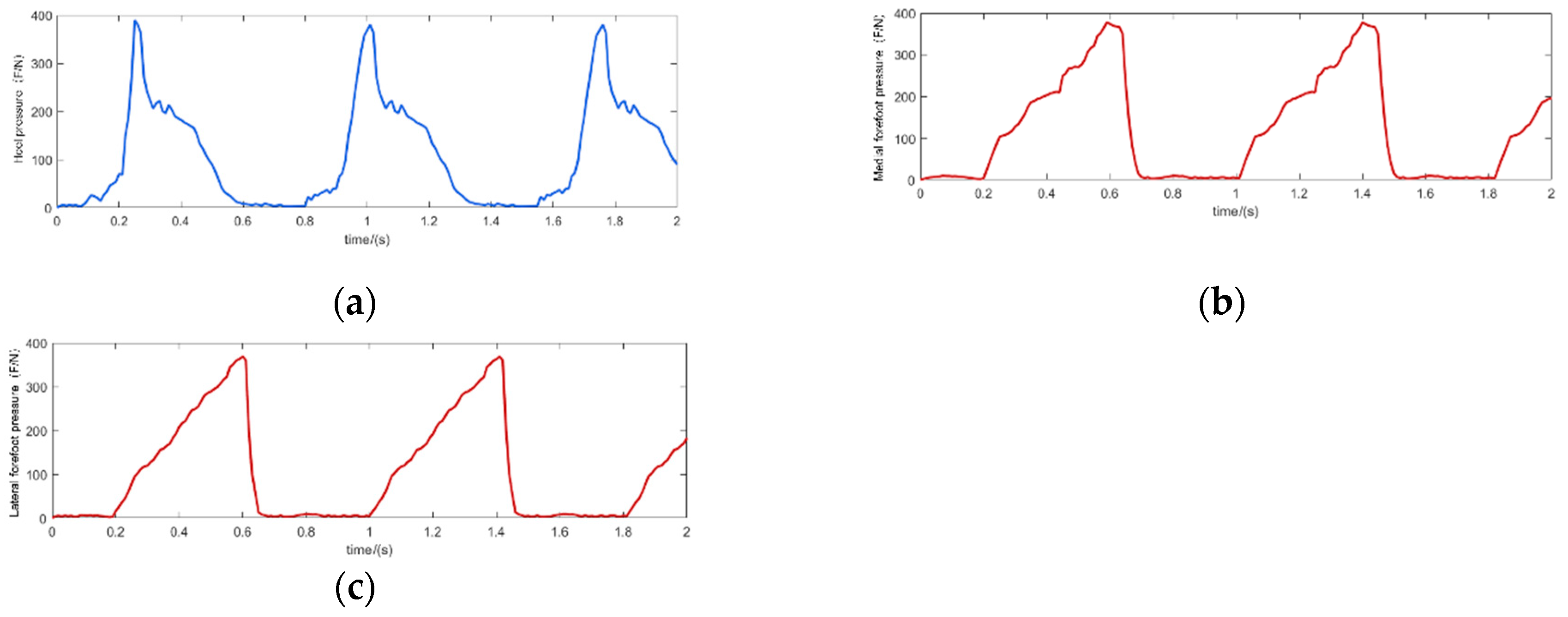
Figure 14, healthy subjects wearing the lower-limb exoskeleton rehabilitation robot performed continuous walking experiments to simulate gait rehabilitation training. Due to the preliminary nature of the prototype testing, healthy participants were used instead of patients to ensure safety. The system successfully replicated the intended gait rehabilitation conditions, allowing for subsequent validation with actual patients in future trials. The experimental conditions were set at a uniform speed of 1 km/h and the subject’s weight was 70 kg. The walking movement experimental process was a reciprocal movement of the subject’s legs, and therefore the plantar pressure appeared to be zero to the overall weight of the human body between the reciprocal changes. As can be seen in
Figure 14 analysis, in the human body during normal walking, when the heel is on the ground, the plantar pressure increases; when the forefoot is not in contact with the ground, there is no pressure (as
Figure 14a), and when the forefoot is on the ground, heel pressure decreases (as
Figure 14b). When the subject walks in normal gait, the pressure and time of the three points show a cyclic pattern, and the pressure on the medial forefoot is slightly larger than that on the lateral forefoot, because the design of the foot soleplate of the lower limb exoskeleton rehabilitation robot is wider than that of a normal human foot, and because the foot soleplate is stiffer, which leads to the change of the pressure distribution. The overall pressure distribution pattern is still cyclic, which is consistent with the cyclic movement characteristics of human gait.
5.3. Lower Limb Exoskeleton Rehabilitation Robot Passive Training Experiments
The passive training mode of lower limb exoskeleton rehabilitation robots aims to enhance patients’ joint mobility during rehabilitation. Prior to conducting gait trajectory tracking experiments, fixed-position testing is essential to both evaluate system performance and establish appropriate parameter selection for subsequent trajectory tracking studies.
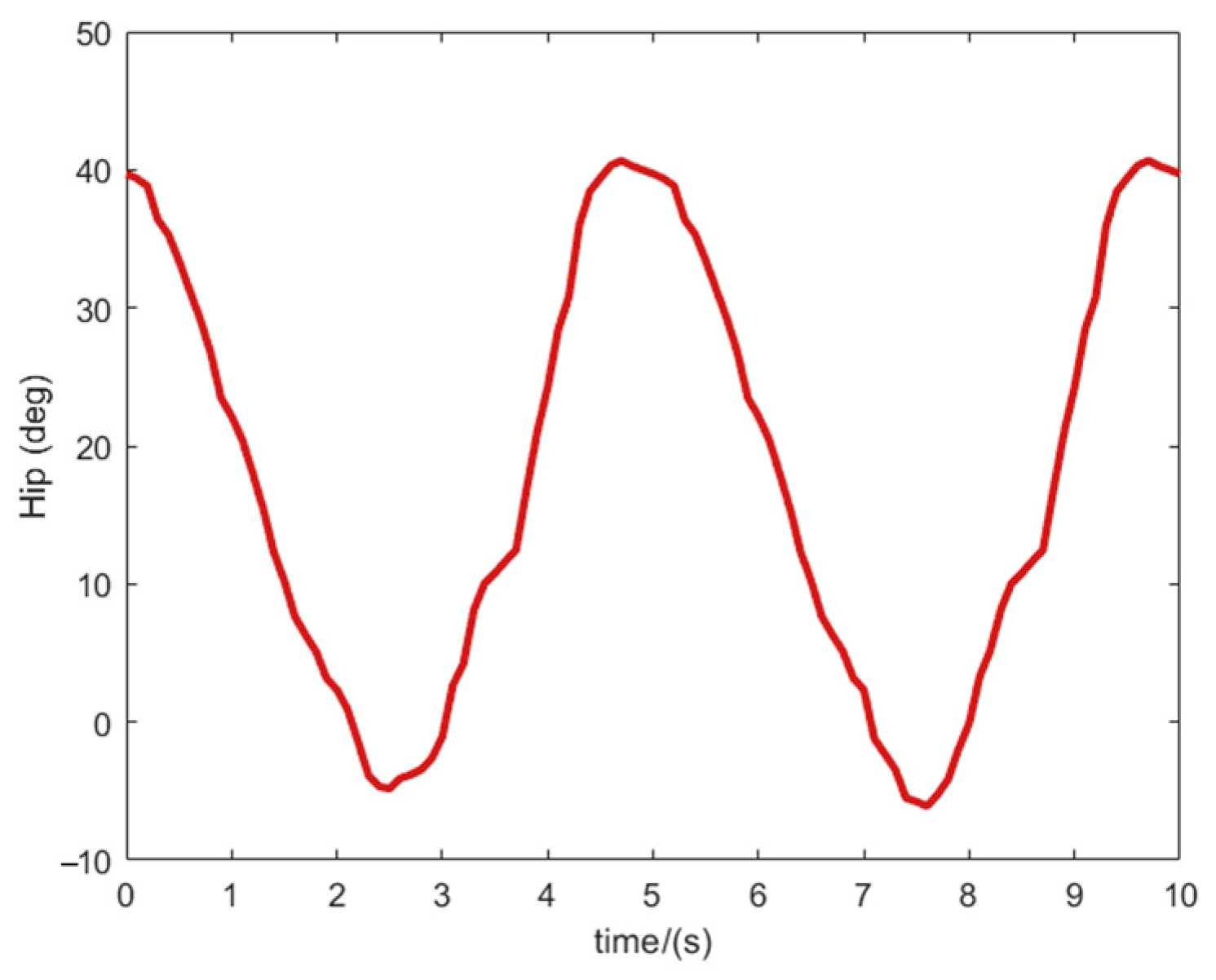
Figure 15 shows the prototype worn by the tester as well as the physical diagram of the control system. During the experiment, the test time of each degree of freedom in each joint of the rehabilitation robot mechanism is set to 20 s, the range of motion is the normal rehabilitation training walking gait angle of the lower limb exoskeleton rehabilitation robot, and the sampling period of the system test is 1 s. The test results are shown in
Figure 16.
Figure 16 shows the lower limb exoskeleton hip flexion/extension and knee flexion/extension patterns, respectively. The red solid line is the simulation result and the blue dashed line is the test result.
Figure 16 demonstrates measurable deviations between simulated and actual joint angles during robotic motion, primarily attributable to mechanical friction-induced errors and inevitable human–robot interaction impedance. Notably, hip flexion/extension demonstrates greater angular deviation due to its role as the primary active DOF driving two passive DOFs. While passive DOFs exhibit higher mobility, their structural configuration contributes to increased positional variance that nevertheless remains within functional tolerance for rehabilitation training. Prototype testing was in agreement with simulation, validating the robot’s capability to successfully execute passive rehabilitation functions [
21,
22,
23].
Figure 15 presents the experimental results of passive training in the lower-limb exoskeleton rehabilitation robot, while
Figure 16a,b depict the hip joint angle tracking curve and knee joint angle tracking error curve, respectively. The figures demonstrate that the exoskeleton robot exhibits a rapid dynamic response with negligible delay, indicating a compact mechanical structure and high-performance joint drive motors. However, the hip joint angular displacement exhibits larger tracking errors than the knee joint, though all errors remain within 0.15 rad. Thus, the joint angular displacement tracking results confirm that the lower-limb rehabilitation exoskeleton robot does not jeopardize human locomotion joints during human-robot cooperative movement. The rehabilitation robot’s joint movement achieves coordinated motion with human lower-limb joints within the controlled angular range. Moreover, the exoskeleton maintains proper alignment with the human body during movement, and the wearer experiences no discomfort, thereby validating the safety, comfort, and efficacy of the rehabilitation training.
5.4. Lower Limb Exoskeleton Rehabilitation Robot Active Training Experiment
During passive gait rehabilitation training, patients demonstrate progressive improvement in lower limb strength. This recovery progression enables transition to active movement training mode. In active mode, the exoskeleton enters a following state with the patient, representing a resistance-enhanced state compared to passive training. Active training operates under predefined human-robot interaction forces to assess: (1) joint movement accuracy, (2) velocity, and (3) other gait parameters. The system simultaneously records kinematic data including trajectory patterns and movement rates [
24,
25,
26,
27].
This study evaluates hip and knee joint actuation to verify the exoskeleton’s ability to synchronize with voluntary human movement. As shown in
Figure 17,
Figure 18,
Figure 19 and
Figure 20, the rehabilitation robot achieves following movement according to the intended movement of the human body. The active gait rehabilitation training mode of the lower extremity exoskeleton rehabilitation robot can meet the requirements of the experimental test, verifying the safety and reliability of the active gait rehabilitation training mode.
6. Conclusions
In this study, we propose a sliding mode control (SMC) method incorporating an RBF neural network and design an RBF-based sliding mode controller. This system aims to assist patients in walking rehabilitation by improving limb functional disorders, thereby providing comfortable and effective gait training. We develop a biomimetic, modular lower-limb exoskeleton rehabilitation robot and address approximation challenges in the RBF neural network caused by uncertainties in lower-limb muscle group perturbations. By substituting neural network weight parameters with adaptive adjustments, we ensure that each joint’s output torque accurately tracks the desired input torque. The global asymptotic stability of the closed-loop exoskeleton system is rigorously proven using Lyapunov’s direct method. Furthermore, we employ a motion capture system to establish a lower-limb skeletal muscle model tailored for patients with leg spasticity. This facilitates the planning of personalized gait trajectories, optimizing rehabilitation efficacy and safety. Finally, we conduct active-passive rehabilitation training experiments to validate the safety and reliability of the proposed gait training model.
Experimental results from flat-ground walking gait trials confirmed the feasibility of the proposed anthropomorphic lower-limb exoskeleton design. Gait training demonstrated close kinematic compatibility between exoskeleton and human movement patterns. To optimize patient safety and rehabilitation efficacy, subjects performed both active and passive training under 3D motion capture monitoring. This enabled the development of a spasticity-stage-appropriate musculoskeletal model and patient-specific optimal trajectory planning. The system achieved maximum angular errors of 1.77° (hip flexion/extension), 1.87° (knee flexion/extension), and 0.72° (ankle flexion/extension). These precision levels satisfy clinical requirements for lower-limb rehabilitation while ensuring both training efficacy and patient safety. The lower-limb exoskeleton satisfies all design specifications and successfully executes motor functions essential for rehabilitation training.


 ,
, 