
A Comprehensive Review of Open Caisson Modeling Technology: Current Practices and Future Prospects

 ,
,  , , ,
, , ,
Abstract
1. Introduction
2. Methodological Route for Study Selection
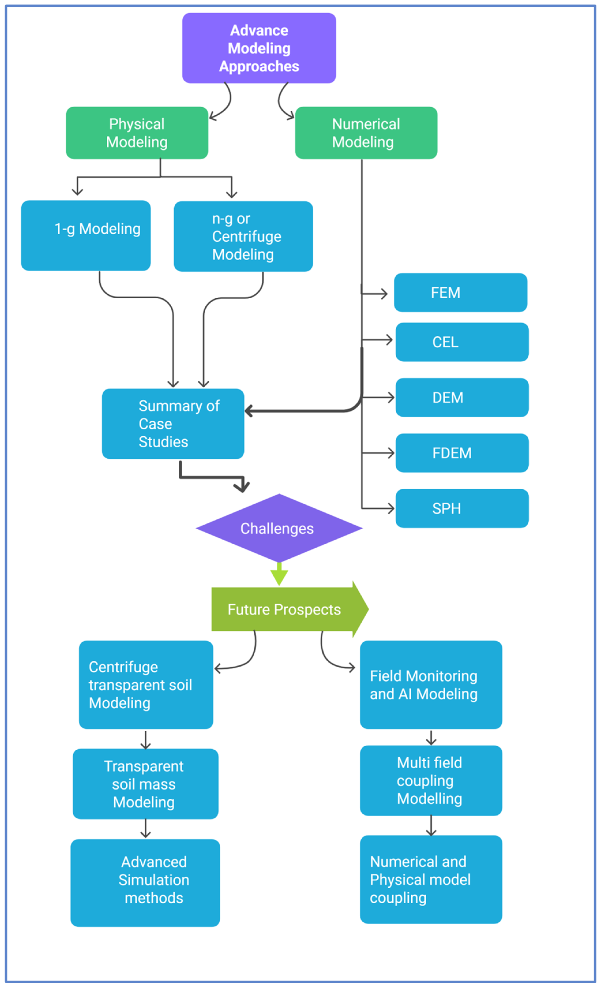
3. Advances in Physical Modeling Method
3.1. Classification of Physical Modeling Based on Gravitational Acceleration
3.2. 1-g Modeling
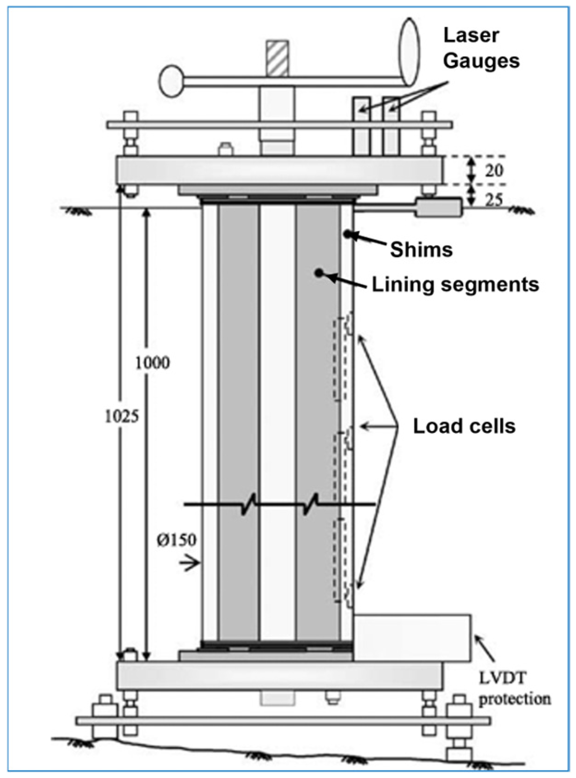
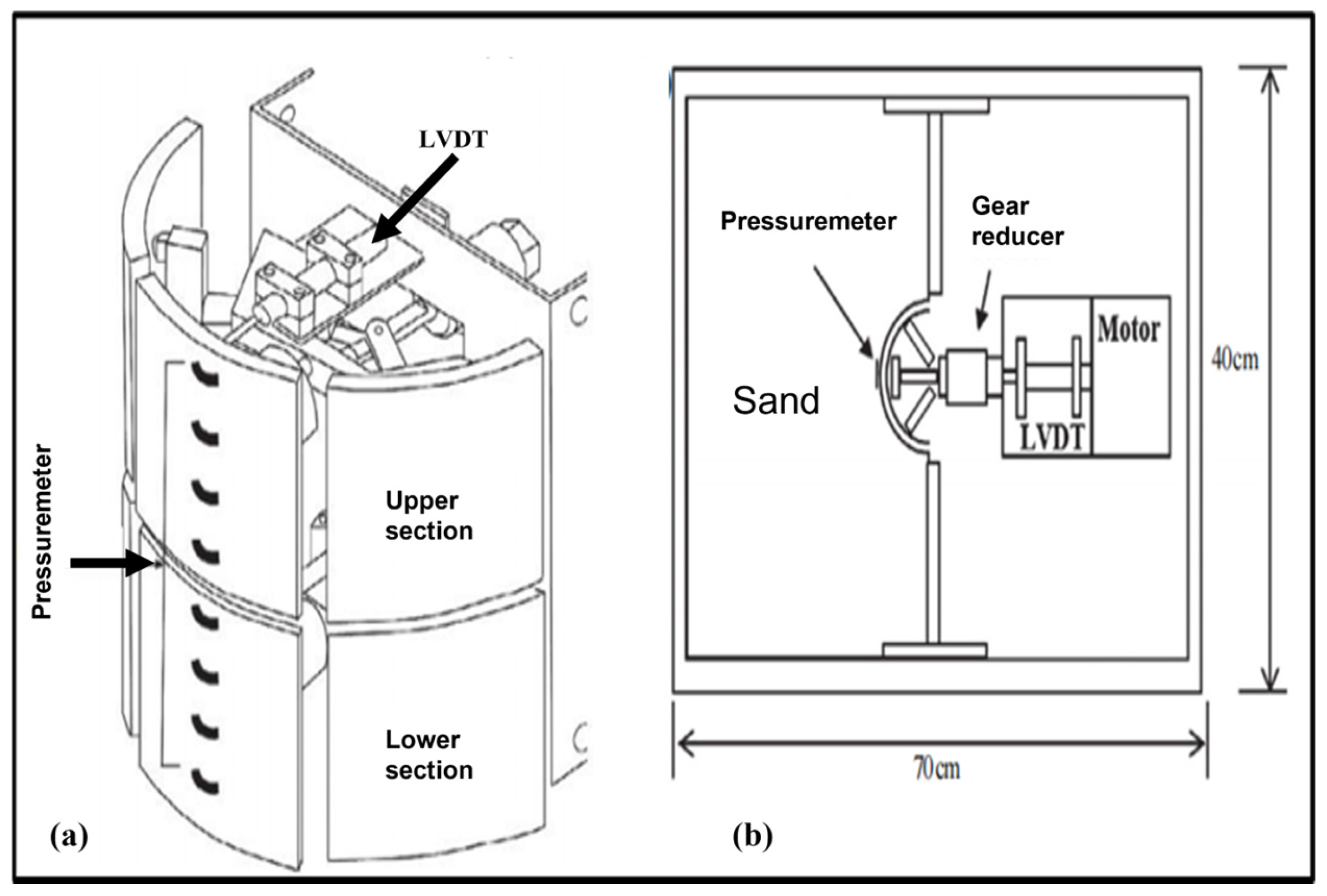
3.2.1. Lateral Earth Pressure Resulting from the Radial Displacement of Shaft Linings
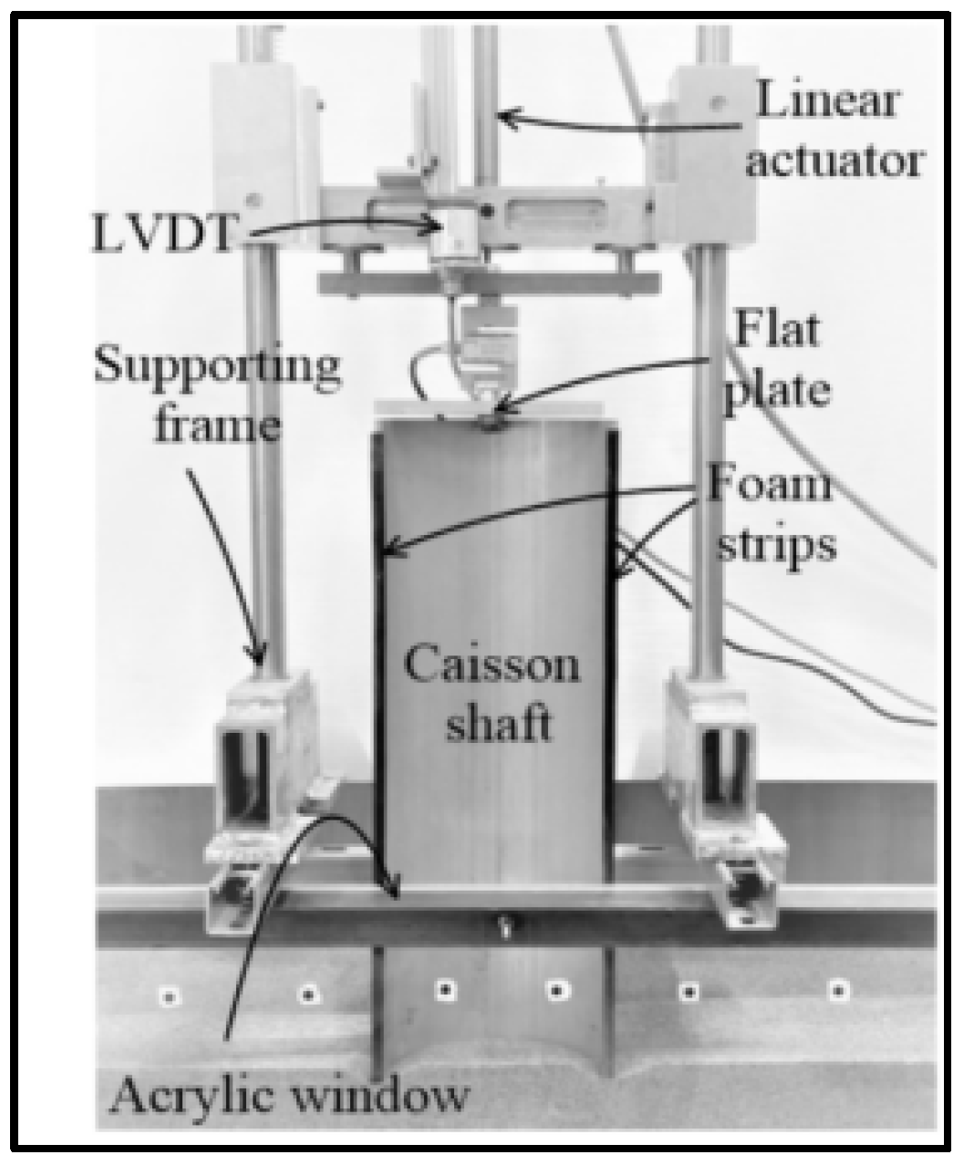
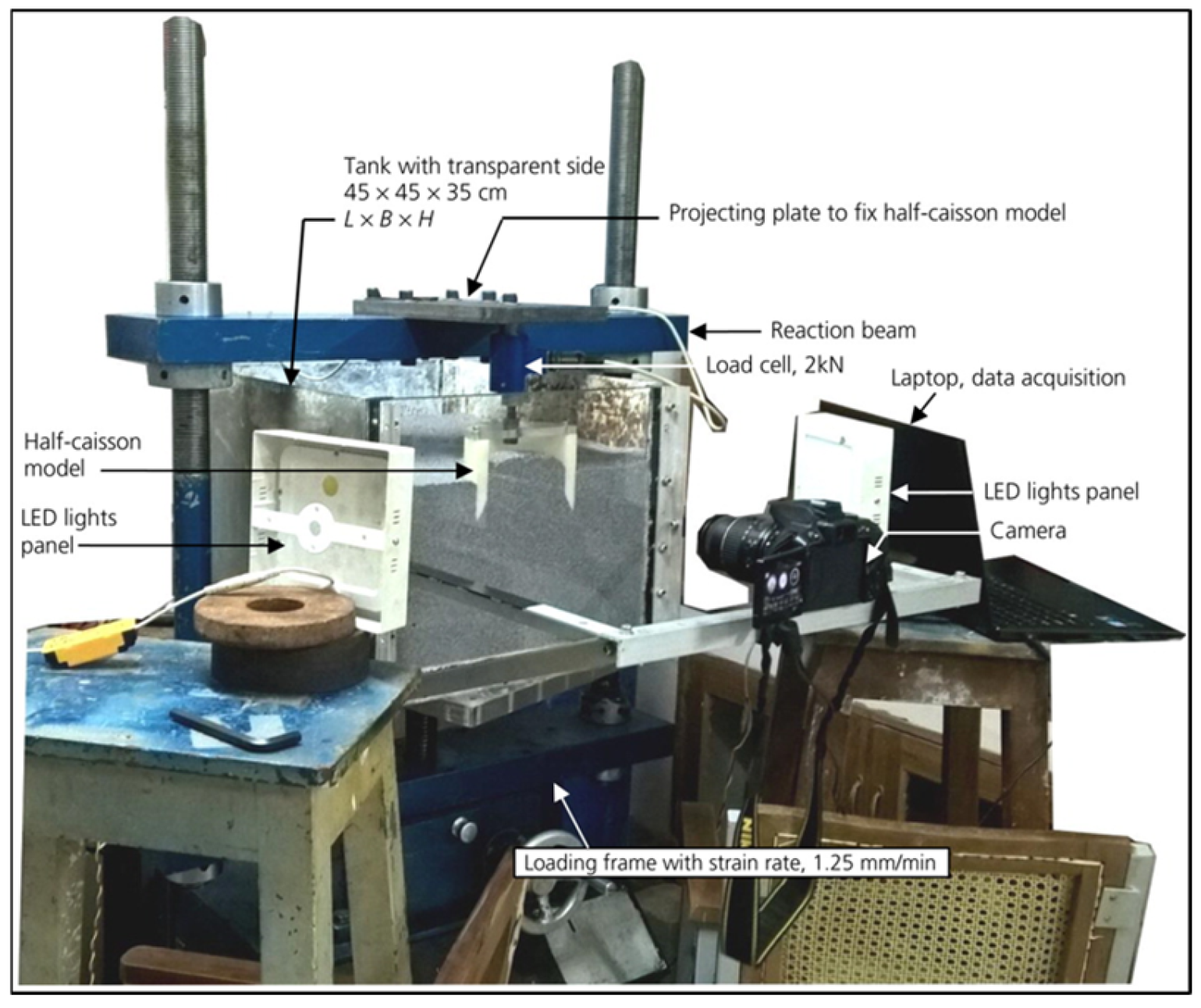
3.2.2. Soil Deformation During Caisson Construction in Dry Sand
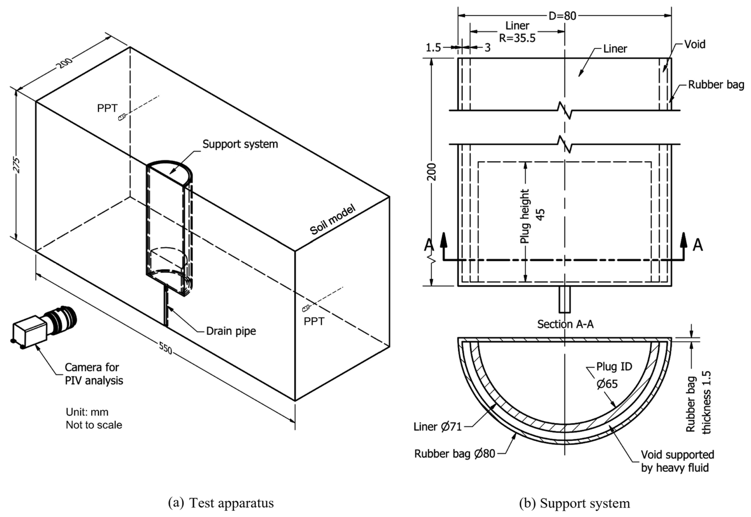
3.2.3. Load–Penetration Behavior and Soil Flow Dynamics in Sandy Soil
3.3. n-g Modeling
3.3.1. Earth Pressure During Excavation Within Granular Soil
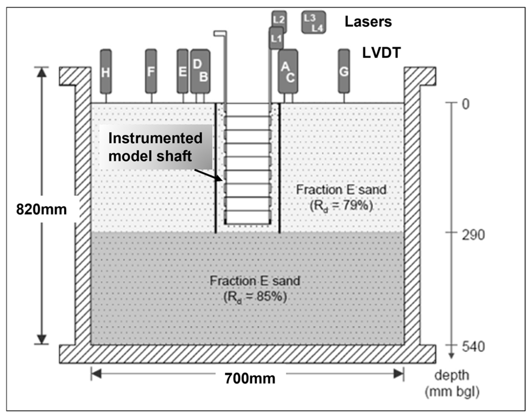
3.3.2. Ground Movements During Excavation Within Dry Dense Sand
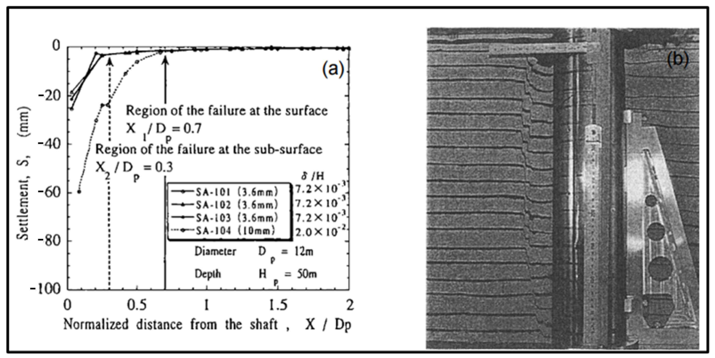
3.3.3. Ground Failure During Excavation Within Granular Soil
3.3.4. Surface and Subsurface Soil Displacements During Excavation Within Cohesive Soil
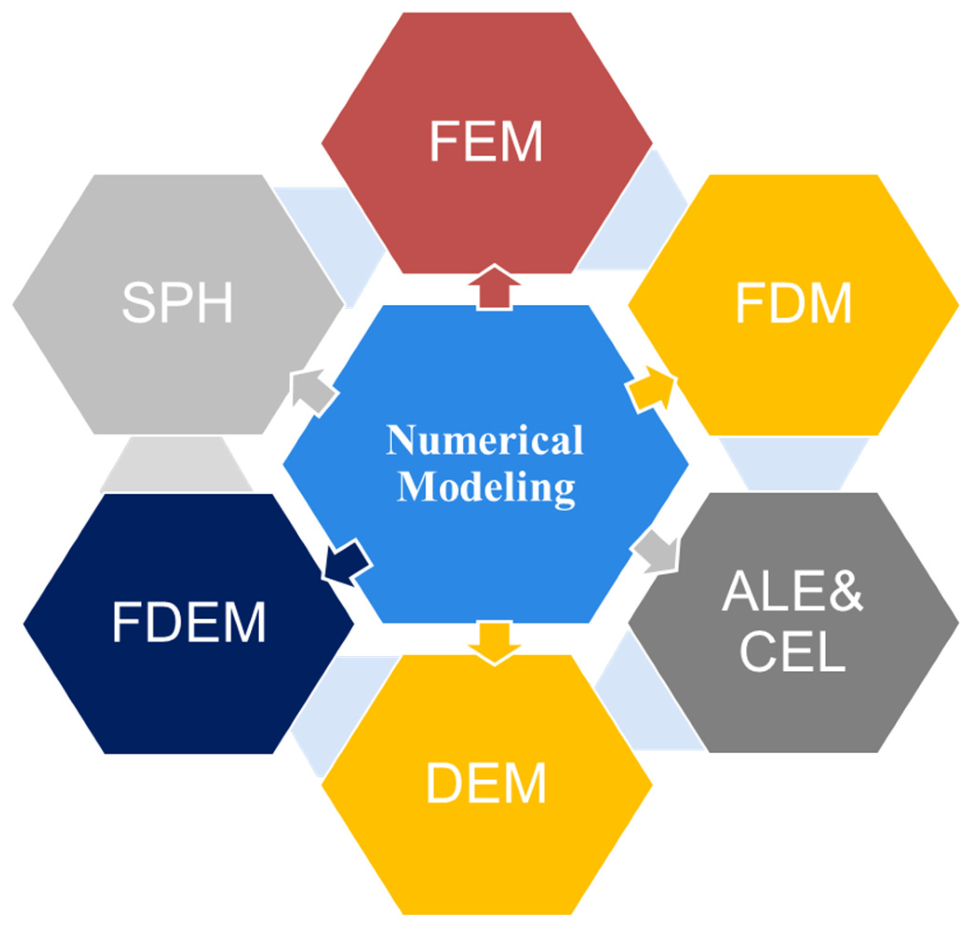
4. Advances in Computational Modeling Method
4.1. FEM
4.2. FDM
4.3. ALE and CEL
4.4. DEM
4.5. FDEM
4.6. SPH
5. Challenges and Future Directions
5.1. Challenges
5.1.1. Soil–Structure Interaction (SSI) Mechanism
5.1.2. Earth Pressure During Sinking
5.1.3. Soil Variability and Unpredictable Subsurface Conditions
5.2. Future Directions
5.2.1. Real-Time Field Monitoring and AI Methods
5.2.2. Multi-Field Coupling Modeling
5.2.3. Advanced Simulation Methods
5.2.4. Transparent Soil Mass Modeling
5.2.5. Centrifuge Transparent Soil Modeling
5.2.6. Numerical and Physical Model Coupling (n-p Coupling)
5.3. Prioritize Direction
6. Conclusions
Author Contributions
Funding
Institutional Review Board Statement
Informed Consent Statement
Data Availability Statement
Acknowledgments
Conflicts of Interest
References
- Sheil, B. Prediction of microtunnelling jacking forces using a probabilistic observational approach. Tunn. Undergr. Space Technol. 2021, 109, 103749. [Google Scholar] [CrossRef]
- Royston, R.; Sheil, B.B.; Byrne, B.W. Monitoring the construction of a large-diameter caisson in sand. Proc. Inst. Civ. Eng.-Geotech. Eng. 2022, 175, 323–339. [Google Scholar] [CrossRef]
- Royston, R.; Sheil, B.B.; Byrne, B.W. Undrained bearing capacity of the cutting face for an open caisson. Géotechnique 2022, 72, 632–641. [Google Scholar] [CrossRef]
- Allenby, D.; Kilburn, D. Overview of underpinning and caisson shaft-sinking techniques. Proc. Inst. Civ. Eng.-Geotech. Eng. 2015, 168, 3–15. [Google Scholar] [CrossRef]
- Allenby, D.; Waley, G.; Kilburn, D. Examples of open caisson sinking in Scotland. Proc. Inst. Civ. Eng.-Geotech. Eng. 2009, 162, 59–70. [Google Scholar] [CrossRef]
- Arthur, L.; Darby, A.; Rafoneke, B.; Daws, G.; MacDonald, D.; Innaurato, N.; Mancini, R.; Rondena, E.; Zaninetti, A.; Coutts, A. Ground movement model validation at the Heathrow Express trial tunnel. In Tunnelling’94: Papers Presented at the Seventh International Symposium,‘Tunnelling’ 94’, London, UK, 5–7 July 1994; Springer US: New York, NY, USA, 1994; pp. 301–329. [Google Scholar]
- Ho, C.E. Settlement performance of large diameter friction caissons in bouldery clay. In Proceedings of the Deep Foundations 2002: An International Perspective on Theory, Design, Construction, and Performance, Orlando, FL, USA, 14–16 February 2002; pp. 525–541. [Google Scholar]
- Sun, Y.; Shen, S.; Xu, Z.; Xia, X. Prediction of lateral displacement of soil behind the reaction wall caused by pipe jacking operation. Tunn. Undergr. Space Technol. 2014, 40, 210–217. [Google Scholar] [CrossRef]
- Guo, M.; Dong, X.; Yang, Z. Settlement analysis of the giant open caisson during the construction of the Changtai Yangtze River Bridge. Front. Earth Sci. 2023, 10, 1056695. [Google Scholar] [CrossRef]
- Jiang, B.-N.; Wang, M.-T.; Chen, T.; Zhang, L.-L.; Ma, J.-L. Experimental study on the migration regularity of sand outside a large, deep-water, open caisson during sinking. Ocean Eng. 2019, 193, 106601. [Google Scholar] [CrossRef]
- Zhou, H.; Zhang, K.; Luo, C.; Yang, B. Centrifugal model test study of caisson sinking resistance. Rock Soil Mech. 2019, 40, 3969–3976. [Google Scholar]
- Templeman, J.O.; Phillips, B.M.; Sheil, B.B. Cutting shoe design for open caissons in sand: Influence on vertical bearing capacity. Proc. Inst. Civ. Eng.-Geotech. Eng. 2023, 176, 58–73. [Google Scholar] [CrossRef]
- Chandler, J.; Hinch, L.; Fair, R.; Hughes, D.; Peraino, J.; Rowe, P. Jamuna river 230 kV crossing, Bangladesh. Part 2: Construction. In IEE Proceedings C (Generation, Transmission and Distribution); IET: Stevenage, UK, 1984; pp. 319–332. [Google Scholar]
- Safiullah, A. Geotechnical problems of bridge construction in Bangladesh. In Proceedings of the Japan-Bangladesh Joint Seminar on Advances in Bridge Engineering, Dacca, Bangladesh, 10 August 2005; pp. 135–146. [Google Scholar]
- Sheil, B.; Royston, R.; Byrne, B. Real-time monitoring of large-diameter caissons. In Springer Series in Geomechanics and Geoengineering, Proceedings of the China-Europe Conference on Geotechnical Engineering, Vienna, Austria, 13–16 August 2016; Springer: Berlin/Heidelberg, Germany, 2018; Volume 1, pp. 725–729. [Google Scholar]
- Guo, M.; Dong, X.; Li, J. Study on the earth pressure during sinking stage of super large caisson foundation. Appl. Sci. 2021, 11, 10488. [Google Scholar] [CrossRef]
- Wood, D.M. Geotechnical Modelling; CRC Press: Boca Raton, FL, USA, 2017. [Google Scholar]
- Wood, D.M. Physical modelling. In Prediction and Simulation Methods in Geomechanics: State-of-the-Art Report on Selected Topics by TC-34; Japanese Geotechnical Society: Bunkyo City, Tokyo, 2005; pp. 7–11. [Google Scholar]
- Askarinejad, A.; Laue, J.; Zweidler, A.; Iten, M.; Bleiker, E.; Buschor, H.; Springman, S.M. Physical modelling of rainfall induced landslides undercontrolled climatic conditions. In Proceedings of the Eurofuge 2012, Delft, The Netherlands, 23–24 April 2012. [Google Scholar]
- Knothe, S. Observations of surface movements under influence of mining and their theoretical interpretation. In Proceedings of the European Congress on Ground Movement, Leeds, UK, 9–12 April 1957; pp. 210–218.
- Wu, L.; Huang, R.; Xu, Q.; Zhang, L.; Li, H. Analysis of physical testing of rainfall-induced soil slope failures. Environ. Earth Sci. 2015, 73, 8519–8531. [Google Scholar] [CrossRef]
- Miao, F.; Wu, Y.; Li, L.; Tang, H.; Li, Y. Centrifuge model test on the retrogressive landslide subjected to reservoir water level fluctuation. Eng. Geol. 2018, 245, 169–179. [Google Scholar] [CrossRef]
- Chueasamat, A.; Hori, T.; Saito, H.; Sato, T.; Kohgo, Y. Experimental tests of slope failure due to rainfalls using 1g physical slope models. Soils Found. 2018, 58, 290–305. [Google Scholar] [CrossRef]
- Zhang, Q.; Duan, K.; Jiao, Y.; Xiang, W. Physical model test and numerical simulation for the stability analysis of deep gas storage cavern group located in bedded rock salt formation. Int. J. Rock Mech. Min. Sci. 2017, 94, 43–54. [Google Scholar] [CrossRef]
- Cho, H.I.; Bang, E.S.; Yi, M.J.; Kim, D.S. Physical modeling of land subsidence due to underground cavity and its monitoring by electrical resistivity survey in geotechnical centrifuge. Jpn. Geotech. Soc. Spec. Publ. 2016, 2, 2469–2472. [Google Scholar] [CrossRef]
- He, M.-C.; Gong, W.-L.; Li, D.-J.; Zhai, H.-M. Physical modeling of failure process of the excavation in horizontal strata based on IR thermography. Min. Sci. Technol. 2009, 19, 689–698. [Google Scholar] [CrossRef]
- Vardoulakis, P.; Stavropoulou, M.; Exadaktylos, G. Sandbox modeling of the shallow tunnel face collapse. Riv. Itall. Geotech. 2009, 1, 9–22. [Google Scholar]
- Moradi, A. Plasmon modes of spherical nanoparticles: The effects of quantum nonlocality. Surf. Sci. 2015, 637, 53–57. [Google Scholar] [CrossRef]
- Xie, Q.; Cao, Z.; Shi, X.; Fu, X.; Ban, Y.; Wu, Z. Model test of interaction between load-caused landslide and double-row anti-slide piles by transparent soil material. Arab. J. Sci. Eng. 2021, 46, 4841–4856. [Google Scholar] [CrossRef]
- Chen, H.-M.; Yu, H.-S.; Smith, M.J. Physical model tests and numerical simulation for assessing the stability of brick-lined tunnels. Tunn. Undergr. Space Technol. 2016, 53, 109–119. [Google Scholar] [CrossRef]
- Meguid, M.; Saada, O.; Nunes, M.; Mattar, J. Physical modeling of tunnels in soft ground: A review. Tunn. Undergr. Space Technol. 2008, 23, 185–198. [Google Scholar] [CrossRef]
- White, D.; Gaudin, C.; Take, W. General report for TC104 physical modelling in geotechnics. In Proceedings of the 18th International Conference on Soil Mechanics and Geotechnical Engineering: Challenges and Innovations in Geotechnics, ICSMGE 2013, Paris, France, 2–6 September 2013; IOS Press: Amsterdam, The Netherlands, 2013. [Google Scholar]
- Green, D. Modelling geomorphic systems: Scaled physical models. In Geomorphological Techniques; British Society for Geomorphology: London, UK, 2014. [Google Scholar]
- Garnier, J. Modèles physiques en géotechnique-I–Évolution des techniques expérimentales et des domaines d’application. Rev. Franç. Géotech. 2001, 97, 3–29. [Google Scholar] [CrossRef]
- Shiau, J.; Sams, M.; Lamb, B. Introducing advanced topics in geotechnical engineering teaching–tunnel modelling. GEOMATE J. 2016, 10, 1698–1705. [Google Scholar] [CrossRef]
- Beguin, R.; Fry, J.-J.; Picault, C.; Courivaud, J.-R.; Faure, Y.-H.; Philippe, P. Control of the risk of dike failure caused by contact erosion. In Proceedings of the 6th International Conference on Scour and Erosion, Paris, France, 29–31 August 2012; pp. 1551–1558. [Google Scholar]
- Al Heib, M.; Emeriault, F.; Nghiem, H.-L. On the use of 1g physical models for ground movements and soil-structure interaction problems. J. Rock Mech. Geotech. Eng. 2020, 12, 197–211. [Google Scholar] [CrossRef]
- Ganasan, R.; Lim, A.; Wijeyesekera, D. Physical and software modelling for challenging soil structure interaction. ARPN J. Eng. Appl. Sci. 2016, 11, 3668–3676. [Google Scholar]
- Houda, M.; Jenck, O.; Emeriault, F.; Briançon, L.; Gotteland, P. Development of a threedimensional small scale model to simulate soil improvement by rigid piles. In Proceedings of the 18th International Conference on Soil Mechanics and Geotechnical Engineering, Paris, France, 2–6 September 2013. [Google Scholar]
- Sreelakshmi, G.; Asha, M.; Suraj, S. Application of the particle image velocimetry to study pile soil interaction. In Proceedings of the Indian Geotechnical Conference (IGC), Chennai, India, 15–17 December 2016; Indian Institute of Technology (IIT) Madras: Chennai, India, 2016. [Google Scholar]
- Giardina, G.; Marini, A.; Hendriks, M.A.; Rots, J.G.; Rizzardini, F.; Giuriani, E. Experimental analysis of a masonry façade subject to tunnelling-induced settlement. Eng. Struct. 2012, 45, 421–434. [Google Scholar] [CrossRef]
- Xu, C.; Liang, L.; Chen, Q.; Luo, W.; Chen, Y.F. Experimental study of soil arching effect under seepage condition. Acta Geotech. 2019, 14, 2031–2044. [Google Scholar] [CrossRef]
- Son, M.; Cording, E.J. Estimation of building damage due to excavation-induced ground movements. J. Geotech. Geoenviron. Eng. 2005, 131, 162–177. [Google Scholar] [CrossRef]
- Laefer, D.F.; Hong, L.T.; Erkal, A.; Long, J.H.; Cording, E.J. Manufacturing, assembly, and testing of scaled, historic masonry for one-gravity, pseudo-static, soil-structure experiments. Constr. Build. Mater. 2011, 25, 4362–4373. [Google Scholar] [CrossRef]
- Marini, A.; Giuriani, E.; Riva, P. Comportamento Sperimentale di Una Facciata in Muratura su Archi Nell’Ipotesi di Cedimento Differenziale di un Pilastro. In Proceedings of the Atti Convegno Nazionale Sperimentazione su Materiali e Strutture, Venice, Italy, 6–7 December 2006. [Google Scholar]
- Moussaei, N.; Khosravi, M.H.; Hossaini, M.F. Physical modeling of tunnel induced displacement in sandy grounds. Tunn. Undergr. Space Technol. 2019, 90, 19–27. [Google Scholar] [CrossRef]
- Chapman, D.; Ahn, S.; Hunt, D.V. Investigating ground movements caused by the construction of multiple tunnels in soft ground using laboratory model tests. Can. Geotech. J. 2007, 44, 631–643. [Google Scholar] [CrossRef]
- Tang, H.; Hu, X.; Xu, C.; Li, C.; Yong, R.; Wang, L. A novel approach for determining landslide pushing force based on landslide-pile interactions. Eng. Geol. 2014, 182, 15–24. [Google Scholar] [CrossRef]
- Li, C.; Wu, J.; Tang, H.; Hu, X.; Liu, X.; Wang, C.; Liu, T.; Zhang, Y. Model testing of the response of stabilizing piles in landslides with upper hard and lower weak bedrock. Eng. Geol. 2016, 204, 65–76. [Google Scholar] [CrossRef]
- Guo, W.D.; Qin, H. Thrust and bending moment of rigid piles subjected to moving soil. Can. Geotech. J. 2010, 47, 180–196. [Google Scholar] [CrossRef]
- Hu, X.; Liu, D.; Zheng, W.; Tannant, D.; Kang, C. 1-g physical modeling in engineering geology and its application of pile-reinforced reservoir landslides. Eng. Geol. 2024, 331, 107450. [Google Scholar] [CrossRef]
- Phillips, R. Ground Deformation in the Vicinity of a Trench Heading; University of Cambridge: Cambridge, UK, 1986. [Google Scholar]
- Britto, A.M.; Kusakabe, O. Stability of axisymmetric excavations in clays. J. Geotech. Eng. 1983, 109, 666–681. [Google Scholar] [CrossRef]
- Faustin, N.E. Performance of Circular Shafts and Ground Behaviour During Construction. PhD Thesis, University of Cambridge, Cambridge, UK, 2017. [Google Scholar]
- New, B. Settlements due to shaft construction. Tunn. Tunn. Int. 2017, 16–17. [Google Scholar]
- Garnier, J.; Gaudin, C.; Springman, S.M.; Culligan, P.; Goodings, D.; Konig, D.; Kutter, B.; Phillips, R.; Randolph, M.; Thorel, L. Catalogue of scaling laws and similitude questions in geotechnical centrifuge modelling. Int. J. Phys. Model. Geotech. 2007, 7, 1–23. [Google Scholar] [CrossRef]
- Taylor, R. Centrifuges in modelling: Principles and scale effects. In Geotechnical Centrifuge Technology; CRC Press: Boca Raton, FL, USA, 2018; pp. 19–33. [Google Scholar]
- Bhattacharya, S.; Demirci, H.E.; Nikitas, G.; Prakhya, G.K.V.; Lombardi, D.; Alexander, N.A.; Aleem, M.; Amani, S.; Mylonakis, G. Physical modeling of interaction problems in geotechnical engineering. In Modeling in Geotechnical Engineering; Elsevier: Amsterdam, The Netherlands, 2021; pp. 205–256. [Google Scholar]
- Tobita, T.; Iai, S.; von der Tann, L.; Yaoi, Y. Application of the generalised scaling law to saturated ground. Int. J. Phys. Model. Geotech. 2011, 11, 138–155. [Google Scholar] [CrossRef]
- Black, J.A. Centrifuge modelling with transparent soil and laser aided imaging. Geotech. Test. J. 2015, 38, 631–644. [Google Scholar] [CrossRef]
- Bradshaw, A.; Giampa, J.; Gerkus, H.; Jalilvand, S.; Fanning, J.; Nanda, S.; Gilbert, R.; Gavin, K.; Sivakumar, V. Scaling considerations for 1-g model horizontal plate anchor tests in sand. Geotech. Test. J. 2016, 39, 1006–1014. [Google Scholar] [CrossRef]
- Gibson, A.D. Physical Scale Modeling of Geotechnical Structures at One-G; California Institute of Technology: Pasadena, CA, USA, 1997. [Google Scholar]
- Meguid, M.; Tobar, T. Distribution of Active Earth Pressure on Vertical Shafts. 2009. Available online: https://www.geogroup.mcgill.ca/Research/Conferences/13-Distribution%20of%20Active%20Earth%20Pressure%20on%20Vertical%20Shafts_Tobar_Meguid_CGC_2009.pdf (accessed on 5 January 2025).
- Song, G.; Sheil, B.B. Laboratory Testing of Construction-Induced Ground Displacements for Open Caisson Shafts in Sand. J. Geotech. Geoenviron. Eng. 2023, 149, 04023086. [Google Scholar] [CrossRef]
- Chavda, J.T.; Dodagoudar, G.R. Experimental studies on a circular open caisson. Int. J. Phys. Model. Geotech. 2022, 22, 70–87. [Google Scholar] [CrossRef]
- Craig, W.H.; Vinogradov, V.V.; Frolovsky, Y.K.; Zaytsev, A.A. Pioneers of centrifuge modelling. Int. J. Phys. Model. Geotech. 2015, 15, 3–18. [Google Scholar] [CrossRef]
- Kim, K.-Y.; Lee, D.-S.; Cho, J.; Jeong, S.-S.; Lee, S. The effect of arching pressure on a vertical circular shaft. Tunn. Undergr. Space Technol. 2013, 37, 10–21. [Google Scholar] [CrossRef]
- Faustin, N.; Mair, R.; Elshafie, M. Development of a new excavation technique for centrifuge testing in sand. In Geotechnical Aspects of Underground Construction in Soft Ground; CRC Press: Boca Raton, FL, USA, 2021; pp. 275–282. [Google Scholar]
- Imamura, S.; Nomoto, T.; Fujii, T.; Hagiwara, T.; Kusakabe, O. Earth pressures acting on a deep shaft and the movements of adjacent ground in sand. In Proceedings of the Geotechnical Aspects of Underground Construction on Soft Ground, Tokyo, Japan, 19–21 July 1996; pp. 647–652. [Google Scholar]
- Le, B.T.; Goodey, R.J.; Divall, S. Subsurface ground movements due to circular shaft construction. Soils Found. 2019, 59, 1160–1171. [Google Scholar] [CrossRef]
- Nakai, T.; Xu, L.; Yamazaki, H. 3D and 2D model tests and numerical analyses of settlements and earth pressures due to tunnel excavation. Soils Found. 1997, 37, 31–42. [Google Scholar] [CrossRef]
- Pang, P. Physical and numerical modelling. In Geotechnical Aspects of Underground Construction in Soft Ground; CRC Press: Boca Raton, FL, USA, 2008; pp. 125–136. [Google Scholar]
- Aydan, Ö.; Ohta, Y.; Geniş, M.; Tokashiki, N.; Ohkubo, K. Response and stability of underground structures in rock mass during earthquakes. Rock Mech. Rock Eng. 2010, 43, 857–875. [Google Scholar] [CrossRef]
- Wang, J.; Liu, X.; Liu, S.; Zhu, Y.; Pan, W.; Zhou, J. Physical model test of transparent soil on coupling effect of cut-off wall and pumping wells during foundation pit dewatering. Acta Geotech. 2019, 14, 141–162. [Google Scholar] [CrossRef]
- Ma, J. Numerical simulation of retaining wall in deep foundation based on COMSOL Multiphysics. Highw. Eng 2018, 1, 256–260. [Google Scholar]
- Li, P.; Song, E.; Zheng, T. Initial sinking method for large open caisson in a highway bridge project. In Proceedings of the China-Europe Conference on Geotechnical Engineering, Vienna, Austria, 13–16 August 2018; Springer: Berlin/Heidelberg, Germany, 2018; Volume 2, pp. 1692–1696. [Google Scholar]
- Jiang, B.-n.; Ma, J.-l.; Chu, J.-l. The influence of soil surrounding the caisson cutting edge to excavation and sinking. In Proceedings of the International Conference on Geotechnical and Earthquake Engineering 2018, Austin, TX, USA, 10–13 June 2018; American Society of Civil Engineers: Reston, VA, USA, 2018; pp. 435–448. [Google Scholar]
- Xiao-qing, Z.; Wei, Z.; Xin, Y.; Jin-chang, W.; Zhong-xuan, Y.; Xiao-nan, G. Experimental study and simulation on deformation characteristics of caissons in sand under horizontal loads. Chin. J. Geotech. Eng. 2021, 43, 80–83. [Google Scholar]
- Lai, F.; Liu, S.; Deng, Y.; Sun, Y.; Wu, K.; Liu, H. Numerical investigations of the installation process of giant deep-buried circular open caissons in undrained clay. Comput. Geotech. 2020, 118, 103322. [Google Scholar] [CrossRef]
- Yang, Q.-R.; Li, M.-G.; Chen, J.-J. Influence of a flexible retaining wall on performance of an adjacent deep excavation. KSCE J. Civ. Eng. 2022, 26, 661–672. [Google Scholar] [CrossRef]
- Dong, X.; Tu, J.; Xu, J.; Cai, L.; Wu, B.; Cai, L. Based on Abaqus finite element analysis software to assist the construction of super large caisson. In Proceedings of the 2023 International Seminar on Computer Science and Engineering Technology (SCSET), New York, NY, USA, 29–30 April 2023; pp. 627–631. [Google Scholar]
- Kumar, M.; Chatterjee, K. A numerical study on lateral load response of caissons in static conditions. In Geo-Congress 2020; American Society of Civil Engineers: Reston, VA, USA, 2020; pp. 15–22. [Google Scholar]
- De Falco, N.; Bilotta, E.; Divall, S.; Goodey, R. Numerical analysis of deep ground movements induced by circular shaft construction. In Proceedings of the 20th International Conference on Soil Mechanics and Geotechnical Engineering, Sydney, Australia, 1–5 May 2023. [Google Scholar]
- Zhou, J.; Liu, C.; Xu, J.; Zhang, Z.; Li, Z. Deformation Mechanism and Control of In-Situ Assembling Caisson Technology in Soft Soil Area under Field Measurement and Numerical Simulation. Materials 2023, 16, 1125. [Google Scholar] [CrossRef]
- Lai, F.; Zhang, N.; Liu, S.; Sun, Y.; Li, Y. Ground movements induced by installation of twin large diameter deeply-buried caissons: 3D numerical modeling. Acta Geotech. 2021, 16, 2933–2961. [Google Scholar] [CrossRef]
- Georgiannou, V.N.; Serafis, A.; Pavlopoulou, E.-M. Analysis of a vertical segmental shaft using 2D & 3D finite element codes. GEOMATE J. 2017, 13, 138–146. [Google Scholar]
- Peng, F.-L.; Wang, H.-L.; Tan, Y.; Xu, Z.-L.; Li, Y.-L. Field measurements and finite-element method simulation of a tunnel shaft constructed by pneumatic caisson method in Shanghai soft ground. J. Geotech. Geoenviron. Eng. 2011, 137, 516–524. [Google Scholar] [CrossRef]
- Sun, Y.; Su, J.-B.; Xia, X.-H.; Xu, Z.-L. Numerical analysis of soil deformation behind the reaction wall of an open caisson induced by horizontal parallel pipe-jacking construction. Can. Geotech. J. 2015, 52, 2008–2016. [Google Scholar] [CrossRef]
- Suwansawat, S.; Einstein, H.H. Artificial neural networks for predicting the maximum surface settlement caused by EPB shield tunneling. Tunn. Undergr. Space Technol. 2006, 21, 133–150. [Google Scholar] [CrossRef]
- Yu, Y.; Bathurst, R.J.; Allen, T.M.; Nelson, R. Physical and numerical modelling of a geogrid-reinforced incremental concrete panel retaining wall. Can. Geotech. J. 2016, 53, 1883–1901. [Google Scholar] [CrossRef]
- Lin, Z.; Zhang, B.-Y.; Yang, D. Simulation study on foundation pit excavation in soft soil considering effect of creep and seepage. Mod. Tunn. Technol. 2020, 57, 91–98. [Google Scholar]
- Shah, R.; Zhao, C.; Lavasan, A.A.; Peila, D.; Schanz, T.; Lucarelli, A. Influencing factors affecting the numerical simulation of the mechanized tunnel excavation using FEM and FDM techniques. In Proceedings of the EUROTUN, Innsbruck, Austria, 18–20 April 2017. [Google Scholar]
- Yin, Z.-Y. Three-dimensional numerical modelling of progressive failure of caisson foundation in sand using a coupled FDM–DEM method. Ocean Eng. 2022, 253, 111332. [Google Scholar] [CrossRef]
- Hamann, T.; Qiu, G.; Grabe, J. Application of a Coupled Eulerian–Lagrangian approach on pile installation problems under partially drained conditions. Comput. Geotech. 2015, 63, 279–290. [Google Scholar] [CrossRef]
- Ko, J.; Jeong, S.; Lee, J.K. Large deformation FE analysis of driven steel pipe piles with soil plugging. Comput. Geotech. 2016, 71, 82–97. [Google Scholar] [CrossRef]
- Grabe, J.; Heins, E. Coupled deformation–seepage analysis of dynamic capacity tests on open-ended piles in saturated sand. Acta Geotech. 2017, 12, 211–223. [Google Scholar] [CrossRef]
- Wang, D.; Bienen, B.; Nazem, M.; Tian, Y.; Zheng, J.; Pucker, T.; Randolph, M.F. Large deformation finite element analyses in geotechnical engineering. Comput. Geotech. 2015, 65, 104–114. [Google Scholar] [CrossRef]
- Dong, Z.; Jin, S.; Cao, X.; He, Z.; Yan, H. Enhanced static simulation process of caisson sinking using the coupled Euler-Lagrange method. Ocean Eng. 2023, 286, 115453. [Google Scholar] [CrossRef]
- Zhou, F.; Zhou, P.; Li, J.; Lin, J.; Ge, T.; Deng, S.; Ren, R.; Wang, Z. Deformation characteristics and failure evolution process of the existing metro station under unilateral deep excavation. Eng. Fail. Anal. 2022, 131, 105870. [Google Scholar] [CrossRef]
- Chen, T.; Zhou, K.; Wei, J.; Liu, X.-C.; Lin, Y.-L.; Zhang, J.; Shen, Q. Excavation influence of triangular-distribution tunnels for wind pavilion group of a metro station. J. Cent. South Univ. 2020, 27, 3852–3874. [Google Scholar] [CrossRef]
- Tran, V.D.; Yacoub, T.E.; Meguid, M.A. On the Analysis of Vertical Shafts in Soft Ground: Evaluating Soil-Structure Interaction Using Two Different Numerical Modeling Techniques. 2013. Available online: https://geogroup.mcgill.ca/Research/Conferences/23-On%20the%20analysis%20of%20vertical%20shafts%20in%20soft%20ground_Tran_et_al_GeoMon2013.pdf (accessed on 24 December 2024).
- Zhang, N.; Arroyo, M.; Ciantia, M.O.; Gens, A.; Butlanska, J. Standard penetration testing in a virtual calibration chamber. Comput. Geotech. 2019, 111, 277–289. [Google Scholar] [CrossRef]
- Long, Y.-Y.; Tan, Y. Soil arching due to leaking of tunnel buried in water-rich sand. Tunn. Undergr. Space Technol. 2020, 95, 103158. [Google Scholar] [CrossRef]
- Zhu, H.-X.; Yin, Z.-Y. Grain rotation-based analysis method for shear band. J. Eng. Mech. 2019, 145, 04019073. [Google Scholar] [CrossRef]
- Zhang, F.; Dontsov, E.; Mack, M. Fully coupled simulation of a hydraulic fracture interacting with natural fractures with a hybrid discrete-continuum method. Int. J. Numer. Anal. Methods Geomech. 2017, 41, 1430–1452. [Google Scholar] [CrossRef]
- Zhu, H.X.; Yin, Z.Y.; Zhang, Q. A novel coupled FDM-DEM modelling method for flexible membrane boundary in laboratory tests. Int. J. Numer. Anal. Methods Geomech. 2020, 44, 389–404. [Google Scholar] [CrossRef]
- Wang, J.; Hua, H.; Lian, W. Penetration simulation for an open caisson using mesh-free SPH method. In Proceedings of the Computer Methods and Recent Advances in Geomechanics, Kyoto, Japan, 22–25 September 2014; pp. 105–109. [Google Scholar]
- Jin, Z.; Yin, Z.-Y.; Kotronis, P.; Jin, Y.-F. Numerical investigation on evolving failure of caisson foundation in sand using the combined Lagrangian-SPH method. Mar. Georesour. Geotechnol. 2019, 37, 23–35. [Google Scholar] [CrossRef]
- Rogers, B.D.; Dalrymple, R.A.; Stansby, P.K. Simulation of caisson breakwater movement using 2-D SPH. J. Hydraul. Res. 2010, 48, 135–141. [Google Scholar] [CrossRef]
- Zhang, J. Numerical simulation on the whole sinking process of open caisson with an improved SPH method. Math. Probl. Eng. 2021, 2021, 6699880. [Google Scholar] [CrossRef]
- Coombs, W. Finite Deformation of Particulate Geomaterials: Frictional and Anisotropic Critical State Elasto-Plasticity; Durham University: Durham, UK, 2011. [Google Scholar]
- Huang, B.; Bathurst, R.J.; Hatami, K. Numerical study of reinforced soil segmental walls using three different constitutive soil models. J. Geotech. Geoenviron. Eng. 2009, 135, 1486–1498. [Google Scholar] [CrossRef]
- Robert, D.; Soga, K.; Britto, A. Soil constitutive models to simulate pipeline-soil interaction behaviour. In Proceedings of the International Conference on Geotechnical Engineering ICGE, Colombo, Sri Lanka, 10–11 August 2015; pp. 347–350. [Google Scholar]
- Do, N.V.; Nghia, D.T.; Tu, P.Q. Stiffness of Soil in Excavation-Induced Deformation Analysis in Vietnam. In Geotechnics for Sustainable Infrastructure Development; Springer: Berlin/Heidelberg, Germany, 2019; pp. 351–354. [Google Scholar]
- Dahal, B.K.; Regmi, S.; Paudyal, K.; Dahal, D.; KC, D. Enhancing Deep Excavation Optimization: Selection of an Appropriate Constitutive Model. CivilEng 2024, 5, 785–800. [Google Scholar] [CrossRef]
- Lim, A.; Ou, C.-Y.; Hsieh, P.-G. Evaluation of clay constitutive models for analysis of deep excavation under undrained conditions. J. Geoengin. 2010, 5, 9–20. [Google Scholar]
- Dawd, S.; Trygg, R. FE analyses of horizontal deformations due to excavation processes in deep layers of soft Gothenburg clay. Master’s Thesis, Chalmers University of Technology, Gothenburg, Sweden, 2013; p. 80. [Google Scholar]
- Huynh, Q.T.; Lai, V.Q.; Tran, V.T.; Nguyen, M.T. Back analysis on deep excavation in the thick sand layer by hardening soil small model. In Proceedings of the ICSCEA 2019: International Conference on Sustainable Civil Engineering and Architecture, Ho Chi Minh, Vietnam, 24–26 October 2019; Springer: Berlin/Heidelberg, Germany, 2020; pp. 659–668. [Google Scholar]
- Mitew-Czajewska, M. Parametric study of deep excavation in clays. Bull. Pol. Acad. Sciences. Tech. Sci. 2018, 66, 747–754. [Google Scholar] [CrossRef]
- Miranda, P.; Vargas Jr, E.; Moraes, A. Evaluation of the Modified Cam Clay model in basin and petroleum system modeling (BPSM) loading conditions. Mar. Pet. Geol. 2020, 112, 104112. [Google Scholar] [CrossRef]
- Carter, J.P. Constitutive modelling in computational geomechanics–61st Rankine lecture, British Geotechnical Association, 2023. Géotechnique 2024, 74, 1511–1535. [Google Scholar] [CrossRef]
- Wheeler, S.J.; Näätänen, A.; Karstunen, M.; Lojander, M. An anisotropic elastoplastic model for soft clays. Can. Geotech. J. 2003, 40, 403–418. [Google Scholar] [CrossRef]
- Yu, H.-S. CASM: A unified state parameter model for clay and sand. Int. J. Numer. Anal. Methods Geomech. 1998, 22, 621–653. [Google Scholar] [CrossRef]
- Atkinson, J. Experimental determination of stress-strain-time characteristics in laboratory and-in-situ tests. General report. In Proceedings of the 10th Soil Mechanics & Foundation Engineering, Florence, Italy, 26–30 May 1991; pp. 915–956. [Google Scholar]
- Tomlinson, M. Foundation Design and Construction Longman Scientific & Technical; Longman Scientific & Technical: Harlow, UK, 1986. [Google Scholar]
- Nonveiller, E. Open caissons for deep foundations. J. Geotech. Eng. 1987, 113, 424–439. [Google Scholar] [CrossRef]
- Puller, M. Deep Excavation; ICE Publishing: London, UK, 2015. [Google Scholar]
- Abdrabbo, F.; Gaaver, K. Challenges and uncertainties relating to open caissons. DFI J. -J. Deep Found. Inst. 2012, 6, 21–32. [Google Scholar] [CrossRef]
- Wang, J.; Chai, L.S.; Wu, H. Numerical simulation on the sinking process of open caisson with particle flow code (PFC). Adv. Mater. Res. 2014, 838, 831–834. [Google Scholar] [CrossRef]
- Royston, R.; Phillips, B.; Sheil, B.; Byrne, B. Bearing capacity beneath tapered blades of open dug caissons in sand. Civ. Eng. Res. Irel. 2016, 2016, 473–478. [Google Scholar]
- Sheil, B.; Templeman, J. Bearing capacity of open caissons embedded in sand. Géotechnique 2021, 73, 495–505. [Google Scholar] [CrossRef]
- Chavda, J.T.; Dodagoudar, G. Finite element evaluation of bearing capacity factors for cutting face of open caissons. Int. J. Geotech. Eng. 2022, 16, 951–961. [Google Scholar] [CrossRef]
- Wu, W.; Yu, H.-S. Proceedings of China-Europe Conference on Geotechnical Engineering; Springer: Berlin/Heidelberg, Germany, 2018; Volume 2. [Google Scholar]
- Royston, R. Investigation of Soil-Structure Interaction for Large Diameter Caissons; University of Oxford: Oxford, UK, 2018. [Google Scholar]
- Tomlinson, M.J.; Boorman, R. Foundation Design and Construction; Pearson Education: Upper Saddle River, NJ, USA, 2001. [Google Scholar]
- Chavda, J.T.; Mishra, S.; Dodagoudar, G.R. Experimental evaluation of ultimate bearing capacity of the cutting edge of an open caisson. Int. J. Phys. Model. Geotech. 2020, 20, 281–294. [Google Scholar] [CrossRef]
- Fischer, G.R.; Gerszewski, W.L.; Barchok, F.J.; Yavarow, M.K. Deep Caisson Sinking in Soft Soils, Grand Forks, North Dakota. 2004. Available online: https://scholarsmine.mst.edu/icchge/5icchge/session01/42/ (accessed on 15 November 2024).
- Ter-Galustov, S.; Ponomarenko, A.; Opershtein, V.; Ivanov, V. Experience in sinking an open caisson in a thixotropic lining. Soil Mech. Found. Eng. 1966, 3, 128–131. [Google Scholar] [CrossRef]
- Newman, T.; Wong, H. Sinking a jacked caisson within the London Basin geological sequence for the Thames Water Ring Main extension. Q. J. Eng. Geol. Hydrogeol. 2011, 44, 221–232. [Google Scholar] [CrossRef]
- Shi, Z.; Li, S.; Yang, S.; Feng, C. Study on the characteristics of friction resistance and the mechanism of sudden sinking in the middle and late sinking stages of super large caisson foundation. Chin. J. Geotech. Eng 2019, 38, 3894–3904. [Google Scholar]
- Westergaard, H.M. Plastic State of Stress Around a Deep Well; Harvard University: Cambridge, MA, USA, 1939. [Google Scholar]
- Terzaghi, K. Theoretical Soil Mechanics; John Wiley & Sons, Inc.: Hoboken, NJ, USA, 1943. [Google Scholar]
- Coulomb, C.A. Essai sur une Application des Regles de Maximis et Minimis a Quelques Problemes de Statique Relatifs a L’architecture (Essay on Maximums and Minimums of Rules to Some Static Problems Relating to Architecture)–TRID; The National Academies of Sciences, Engineering, and Medicine: Washington, DC, USA, 1973. [Google Scholar]
- Rankine, W.J.M., II. On the Stability of Loose Earth; Philosophical Transactions of the Royal Society of London: London, UK, 1857; pp. 9–27. [Google Scholar]
- Liu, F.; Wang, J. A generalized slip line solution to the active earth pressure on circular retaining walls. Comput. Geotech. 2008, 35, 155–164. [Google Scholar] [CrossRef]
- Derezantzev, V. Earth pressure on the cylindrical retaining walls. In Proceedings of the Brussels Conference on Earth Pressure Problems, II, Brussels, Belgium, September 1958; pp. 21–27. [Google Scholar]
- Cheng, Y.M.; Au, S.; Hu, Y.; Wei, W. Active pressure for circular cut with Berezantzev’s and Prater’s theories, numerical modeling and field measurements. Soils Found. 2008, 48, 621–631. [Google Scholar] [CrossRef]
- Liu, F.; Wang, J.; Zhang, L. Axi-symmetric active earth pressure obtained by the slip line method with a general tangential stress coefficient. Comput. Geotech. 2009, 36, 352–358. [Google Scholar] [CrossRef]
- Guojun, X.; Jianhua, W. A rigorous characteristic line theory for axisymmetric problems and its application in circular excavations. Acta Geotech. 2020, 15, 439–453. [Google Scholar] [CrossRef]
- Wong, R.; Kaiser, P. Design and performance evaluation of vertical shafts: Rational shaft design method and verification of design method. Can. Geotech. J. 1988, 25, 320–337. [Google Scholar] [CrossRef]
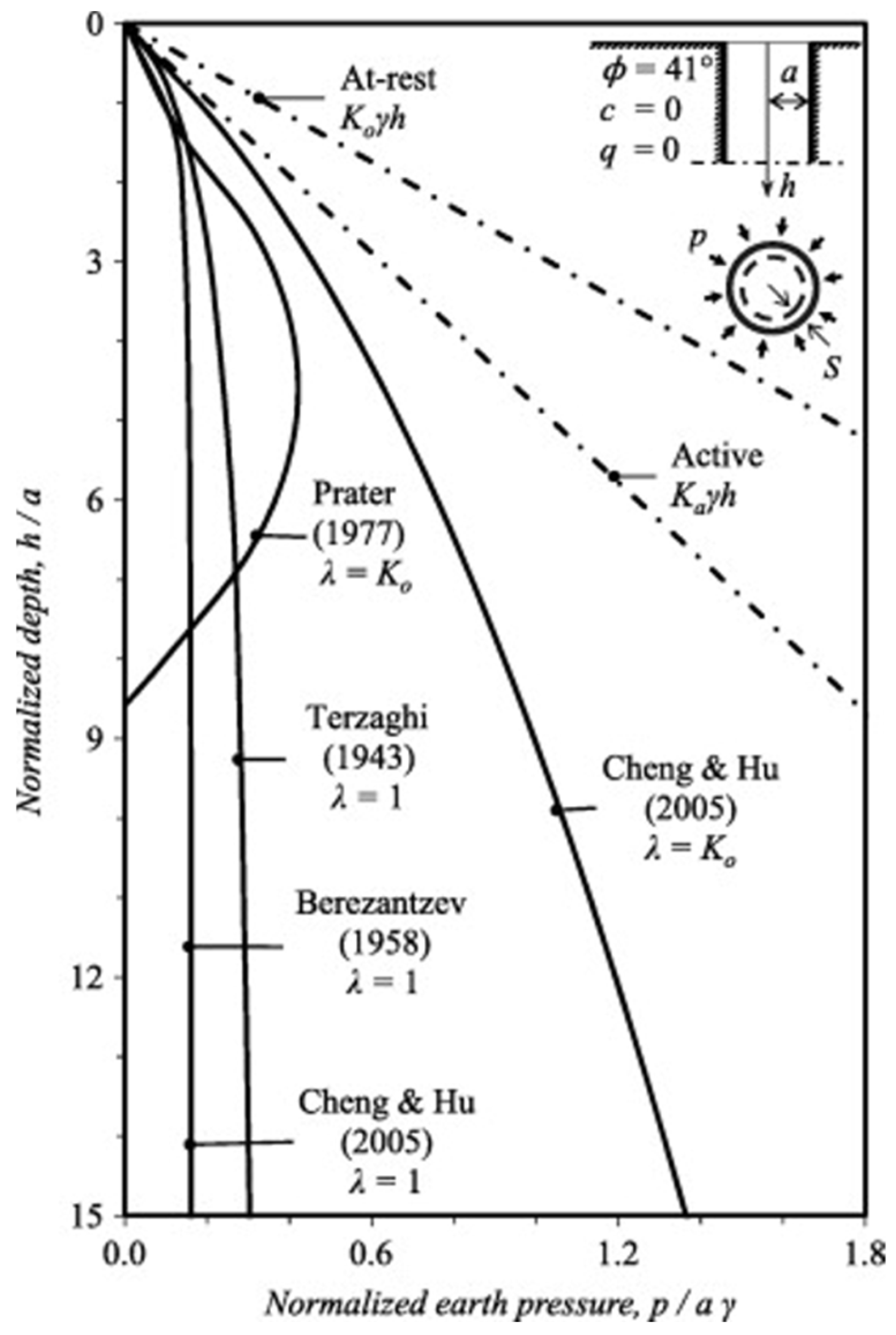
- Prater, E. An examination of some theories of earth pressure on shaft linings. Can. Geotech. J. 1977, 14, 91–106. [Google Scholar] [CrossRef]
- Cheng, Y.; Hu, Y. Active earth pressure on circular shaft lining obtained by simplified slip line solution with general tangential stress coefficient. Chin. J. Geotech. Eng. 2005, 27, 110–115. [Google Scholar]
- Tobar, T.; Meguid, M.A. Comparative evaluation of methods to determine the earth pressure distribution on cylindrical shafts: A review. Tunn. Undergr. Space Technol. 2010, 25, 188–197. [Google Scholar] [CrossRef]
- Luo, C. Settlement Monitoring and Numerical Simulation Analysis of Super-Deep and Large Caisson Foundation. Master’s Thesis, Southwest Jiaotong University, Chengdu, China, 2019. [Google Scholar]
- Yan, F.; Shi, G. Analysis of limiting soil resistance beneath cutting curb during sinking of open caisson. Rock Soil Mech. 2013, 34, 80–87. [Google Scholar]
- Zhang, Z.; Deng, Y.; Zheng, F.; Wang, J. Analysis on sudden sinking behaviors of massive open caisson in deep-thick soft clay area. Chin. J. Undergr. Space Eng. 2020, 16, 933–943. [Google Scholar]
- Mu, B.; Wang, Y.; Zhu, J.; Gong, W.; Ouyang, Z. Analysis of large caisson sinking measured resistance. J. Civ. Archit. Environ. Eng. 2012, 33, 107–115. [Google Scholar]
- Qin, S.; Yuan, R.; Zheng, Q.; Fu, Z.; Ma, R.; Xu, L. Research on structural systems for very long-span rail-cum-road cable-stayed bridge. Bridge Constr. 2020, 50, 1–8. [Google Scholar]
- Walz, B. Left bracket apparatus for measuring the three-dimensional active soil pressure on a round model caisson right bracket. Baumasch. Bautech. 1973, 20, 339–344. [Google Scholar]
- Tobar, T.; Meguid, M.A. Experimental study of the earth pressure distribution on cylindrical shafts. J. Geotech. Geoenviron. Eng. 2011, 137, 1121–1125. [Google Scholar] [CrossRef]
- Tran, V.D.; Meguid, M.A.; Chouinard, L.E. A discrete element study of the earth pressure distribution on cylindrical shafts. In Proceedings of the Tunnelling Association of Canada (TAC) Conference 2012, Montreal, QC, Canada, 17–20 October 2012. [Google Scholar]
- Tran, V.D.; Meguid, M.A.; Chouinard, L.E. Discrete element and experimental investigations of the earth pressure distribution on cylindrical shafts. Int. J. Geomech. 2014, 14, 80–91. [Google Scholar] [CrossRef]
- Yan, X.; Zhan, W.; Hu, Z.; Xiao, D.; Yu, Y.; Wang, J. Field study on deformation and stress characteristics of large open caisson during excavation in deep marine soft clay. Adv. Civ. Eng. 2021, 2021, 7656068. [Google Scholar] [CrossRef]
- Jiang, B.; Ma, J.; Li, M.; Chu, J. Experiments on spatial stress of foot blade during caisson sinking in water. Rock Soil Mech. 2019, 40, 1693–1703. [Google Scholar]
- Gerolymos, N.; Gazetas, G. Development of Winkler model for static and dynamic response of caisson foundations with soil and interface nonlinearities. Soil Dyn. Earthq. Eng. 2006, 26, 363–376. [Google Scholar] [CrossRef]
- Chiou, J.-S.; Ko, Y.-Y.; Hsu, S.-Y.; Tsai, Y.-C. Testing and analysis of a laterally loaded bridge caisson foundation in gravel. Soils Found. 2012, 52, 562–573. [Google Scholar] [CrossRef]
- Schwamb, T. Performance Monitoring and Numerical Modelling of a Deep Circular Excavation. 2014. Available online: https://www.repository.cam.ac.uk/items/04ec45a9-4b8b-4ece-b848-7806d4636412 (accessed on 5 December 2024).
- Schwamb, T.; Elshafie, M.Z.; Soga, K.; Mair, R.J. Considerations for monitoring of deep circular excavations. Proc. Inst. Civ. Eng.-Geotech. Eng. 2016, 169, 477–493. [Google Scholar] [CrossRef]
- Schwamb, T.; Soga, K.; Mair, R.J.; Elshafie, M.Z.; Sutherden, R.; Boquet, C.; Greenwood, J. Fibre optic monitoring of a deep circular excavation. Proc. Inst. Civ. Eng.-Geotech. Eng. 2014, 167, 144–154. [Google Scholar] [CrossRef]
- Chen, Y.; Zhang, R.; Li, Z. Automatic monitoring and structural stress analysis during ultra-large onshore caisson sinking construction. Results Eng. 2024, 21, 101951. [Google Scholar] [CrossRef]
- Dong, X.; Guo, M.; Wang, S. Inclination prediction of a giant open caisson during the sinking process using various machine learning algorithms. Ocean Eng. 2023, 269, 113587. [Google Scholar] [CrossRef]
- Zhi, W. This ACPP technology system provides a new solution for underground space construction [N]. Securities Times, 30 October 2024. [Google Scholar]
- Wang, J.; Abbasi, N.S.; Pan, W.; Alidekyi, S.N.; Li, H.; Ahmed, B.; Asghar, A. A Review of Vertical Shaft Technology and Application in Soft Soil for Urban Underground Space. Appl. Sci. 2025, 15, 3299. [Google Scholar] [CrossRef]
- Zar, A.; Hussain, Z.; Akbar, M.; Rabczuk, T.; Lin, Z.; Li, S.; Ahmed, B. Towards vibration-based damage detection of civil engineering structures: Overview, challenges, and future prospects. Int. J. Mech. Mater. Des. 2024, 20, 591–662. [Google Scholar] [CrossRef]
- Dong, X.; Guo, M.; Wang, S. Advanced prediction of the sinking speed of open caissons based on the spatial-temporal characteristics of multivariate structural stress data. Appl. Ocean Res. 2022, 127, 103330. [Google Scholar] [CrossRef]
- Guo, M.; Dong, X.; Shen, K.; Wang, S.; Lan, G.; Chen, Z. Study on the variation of the bottom resistance during sinking stage of super large caisson foundation. Chin. J. Rock Mech. Eng. 2021, 40, 2976–2985. [Google Scholar]
- Tian, W.; Li, H.; Wang, Y.; Zhu, Y.; Zhu, H.; Li, K. Data-Driven Decision Algorithm for Open Caisson Foundation Construction. Adv. Civ. Eng. 2024, 2024, 9373931. [Google Scholar] [CrossRef]
- Song, G.; He, Y.; Sheil, B.; Morris, J. Ground settlement prediction for open caisson shafts in sand using a neural network constrained by empiricism. Comput. Geotech. 2024, 166, 106001. [Google Scholar] [CrossRef]
- Shuman, N.M.; Khan, M.S.; Amini, F. Efficient machine learning model for settlement prediction of large diameter helical pile in c—Φ soil. AI Civ. Eng. 2024, 3, 10. [Google Scholar] [CrossRef]
- Zhang, P.; Yin, Z.-Y.; Jin, Y.-F. Machine learning-based modelling of soil properties for geotechnical design: Review, tool development and comparison. Arch. Comput. Methods Eng. 2021, 29, 1229–1245. [Google Scholar] [CrossRef]
- Wang, Y.; Tian, H.-M. Digital geotechnics: From data-driven site characterisation towards digital transformation and intelligence in geotechnical engineering. Georisk Assess. Manag. Risk Eng. Syst. Geohazards 2024, 18, 8–32. [Google Scholar] [CrossRef]
- Shahin, M.A. A review of artificial intelligence applications in shallow foundations. Int. J. Geotech. Eng. 2015, 9, 49–60. [Google Scholar] [CrossRef]
- Bozorgzadeh, N.; Feng, Y. Evaluation structures for machine learning models in geotechnical engineering. Georisk Assess. Manag. Risk Eng. Syst. Geohazards 2024, 18, 52–59. [Google Scholar] [CrossRef]
- Li, K.-Q.; Yin, Z.-Y. State of the art of coupled thermo–hydro-mechanical–chemical modelling for frozen soils. Arch. Comput. Methods Eng. 2024, 32, 1039–1096. [Google Scholar] [CrossRef]
- Huang, Y.; Lei, Z.; Lipnikov, K.; Moulton, J.; Sweeney, M.; Hyman, J.; Knight, E.; Stauffer, P. Modeling Coupled Thermo-Hydro-Mechanical-Chemical Processes in Subsurface Geological Media. In Proceedings of the ARMA US Rock Mechanics/Geomechanics Symposium, Atlanta, GA, USA, 25–28 June 2023; ARMA: Atlanta, GA, USA, 2023. [Google Scholar]
- Jing, L.; Feng, X. Numerical modeling for coupled thermo-hydro-mechanical and chemical processes (THMC) of geological media—International and Chinese experiences. Chin. J. Rock Mech. Eng. 2003, 22, 1704–1715. [Google Scholar]
- Wang, J.; Ahmed, B.; Huang, J.; Nong, X.; Xiao, R.; Abbasi, N.S.; Alidekyi, S.N.; Li, H. Physical and Mechanical Properties and Constitutive Model of Rock Mass Under THMC Coupling: A Comprehensive Review. Appl. Sci. 2025, 15, 2230. [Google Scholar] [CrossRef]
- Chen, G.; Li, D.; Chen, J.; Chen, H.; Wang, J.; Jia, Z.; Sun, Q.; Xia, M. Experimental analysis of the thermo-hydro-mechanical (THM) coupling in freezing vertical shafts of unsaturated sandy soil. Cold Reg. Sci. Technol. 2024, 228, 104254. [Google Scholar] [CrossRef]
- Qi, C.; Fan, G.; Cui, Y.; Zhang, Q. Geotechnical physical model test using artificial synthetic transparent soil. Rock Soil Mech. 2015, 36, 3157–3163. [Google Scholar]
- Iskander, M. Transparent soils turn 25: Past, present, and future. In Physical Modelling in Geotechnics; CRC Press: Boca Raton, FL, USA, 2018; Volume 1, pp. 389–394. [Google Scholar]
- Allersma, H.G. Determination of the stress distribution in assemblies of photoelastic particles: Theoretical and experimental description of the application of the photoelasticity method to three-dimensional assemblies of glass particles. Exp. Mech. 1982, 22, 336–341. [Google Scholar] [CrossRef]
- Konagai, K.; Tamura, C.; Rangelow, P.; Matsushima, T. Laser-aided tomography: A tool for visualization of changes in the fabric of granular assemblage. Doboku Gakkai Ronbunshu 1992, 1992, 25–33. [Google Scholar] [CrossRef]
- Iskander, M.G.; Liu, J.; Sadek, S. Transparent amorphous silica to model clay. J. Geotech. Geoenviron. Eng. 2002, 128, 262–273. [Google Scholar] [CrossRef]
- Sadek, S.; Iskander, M.G.; Liu, J. Geotechnical properties of transparent silica. Can. Geotech. J. 2002, 39, 111–124. [Google Scholar] [CrossRef]
- Ganiyu, A.A.; Rashid, A.S.A.; Osman, M.H. Utilisation of transparent synthetic soil surrogates in geotechnical physical models: A review. J. Rock Mech. Geotech. Eng. 2016, 8, 568–576. [Google Scholar] [CrossRef]
- Zhao, H.; Ge, L. Dynamic properties of transparent soil. In Dynamic Response and Soil Properties; ASCE: Reston, VA, USA, 2007; pp. 1–9. [Google Scholar]
- Liu, J.; Iskander, M.G.; Sadek, S. Consolidation and permeability of transparent amorphous silica. Geotech. Test. J. 2003, 26, 390–401. [Google Scholar] [CrossRef]
- Zhao, H.; Ge, L. Investigation on the shear moduli and damping ratios of silica gel. Granul. Matter 2014, 16, 449–456. [Google Scholar] [CrossRef]
- Guzman, I.L.; Iskander, M. Geotechnical properties of sucrose-saturated fused quartz for use in physical modeling. Geotech. Test. J. 2013, 36, 448–454. [Google Scholar] [CrossRef]
- Toiya, M.; Hettinga, J.; Losert, W. 3D Imaging of particle motion during penetrometer testing: From microscopic to macroscopic soil mechanics. Granul. Matter 2007, 9, 323–329. [Google Scholar] [CrossRef]
- Zhao, H. Development and Assessment of Transparent Soil and Particle Image Velocimetry in Dynamic Soil-Structure Interaction; Missouri University of Science and Technology, Center for Infrastructure: Rolla, MO, USA, 2007. [Google Scholar]
- Liu, J.; Liu, M.; Gao, H. Influence of pile geometry on internal sand displacement around a laterally loaded pile using transparent soil. In Deep Foundations and Geotechnical In Situ Testing; ASCE: Westford, MA, USA, 2010; pp. 104–110. [Google Scholar]
- Lwti, N.K. Assessment of Disturbance Impact of Hydraulic Jack in Pile Penetration Using Artificial Transparent Clay; Universiti Teknologi Malaysia: Johor Bharu, Malaysia, 2015. [Google Scholar]
- Liu, J. Visualization of Three-Dimensional Deformations Using Transparent “Soil” Models; Polytechnic University: Toronto, ON, Canada, 2003. [Google Scholar]
- White, D.J.; Take, W.A.; Bolton, M.D. Discussion of “Accuracy of digital image correlation for measuring deformations in transparent media” by Samer Sadek, Magued G. Iskander, and Jinyuan Liu. J. Comput. Civ. Eng. 2005, 19, 217–219. [Google Scholar] [CrossRef]
- Beckett, C.; Augarde, C. A novel image-capturing technique for the experimental study of soil deformations during compaction. Geotech. Test. J. 2011, 34, 571–578. [Google Scholar] [CrossRef]
- Ahmed, M. Investigation of Tunnel Face Stability and Ground Movements Using Transparent Soil Models; Polytechnic Institute of New York University: New York, NY, USA, 2011. [Google Scholar]
- Ahmed, M.; Iskander, M. Tunnel face support pressure and associated risk. In Geo-Risk 2011: Risk Assessment and Management; ASCE: Reston, VA, USA, 2011; pp. 939–947. [Google Scholar]
- Sadek, S.; Iskander, M.G.; Liu, J. Accuracy of digital image correlation for measuring deformations in transparent media. J. Comput. Civ. Eng. 2003, 17, 88–96. [Google Scholar] [CrossRef]
- Taylor, R.N. Geotechnical Centrifuge Technology; CRC Press: Boca Raton, FL, USA, 2018. [Google Scholar]
- Stanier, S.A.; Blaber, J.; Take, W.A.; White, D. Improved image-based deformation measurement for geotechnical applications. Can. Geotech. J. 2016, 53, 727–739. [Google Scholar] [CrossRef]
- Le, B.; Nadimi, S.; Goodey, R.; Taylor, R. System to measure three-dimensional movements in physical models. Géotech. Lett. 2016, 6, 256–262. [Google Scholar] [CrossRef]
- Song, Z.; Hu, Y.; Wang, D.; O’Loughlin, C. Pullout capacity and rotational behaviour of square anchors. In Pullout Capacity and Rotational Behaviour of Square Anchors; Taylor & Francis: Abingdon, UK, 2006; pp. 1325–1331. [Google Scholar]
- Song, Z.; Hu, Y.; O’Loughlin, C.; Randolph, M.F. Loss in anchor embedment during plate anchor keying in clay. J. Geotech. Geoenviron. Eng. 2009, 135, 1475–1485. [Google Scholar] [CrossRef]
- Blakeborough, A.; Williams, M.; Darby, A.; Williams, D. The development of real–time substructure testing. Philos. Trans. R. Soc. Lond. Ser. A Math. Phys. Eng. Sci. 2001, 359, 1869–1891. [Google Scholar] [CrossRef]
- Kong, V.; Cassidy, M.J.; Gaudin, C. Development of a real-time hybrid testing method in a centrifuge. Int. J. Phys. Model. Geotech. 2015, 15, 169–190. [Google Scholar] [CrossRef]


| Study Description | Ground Conditions | Construction Method | Shaft Geometry (H × D) m | Type of Model Test |
|---|---|---|---|---|
| Model caisson sinking | Dry Sand | Model caisson sinking Internal soil excavation | 20 × 32 | 1-g model test |
| Model caisson sinking | Sandy soil | Model caisson sinking, Internal soil excavation | ------ | 1-g model test |
| Pre-installed lining segments | Loose Sand | Pre-installed lining segments | 1 × 0.15 * | 1-g model test |
| Pre-installed shaft lining | Granular soil | Pre-installed shaft lining | 50 × 12 | Centrifuge test at 100× g |
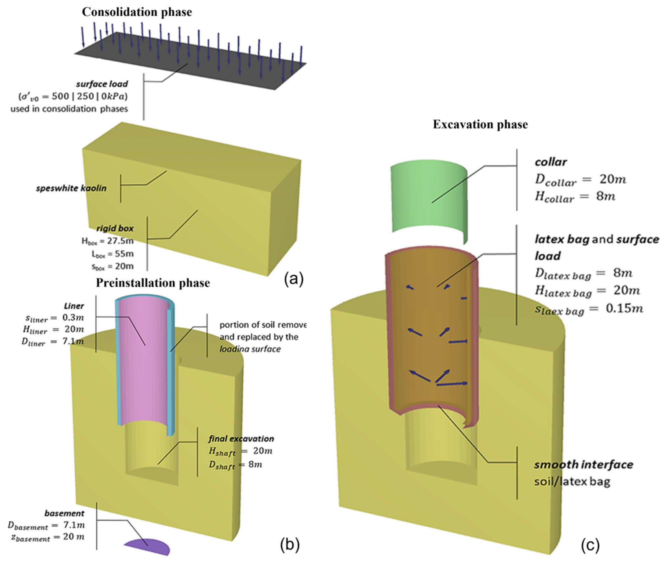
| Pre-installed shaft lining | Speswhite kaolin | Pre-installed shaft lining | 20 × 8 | Centrifuge test at 100× g |
| Shaft construction | Granular soil | Not specified | 200 × 80 * | Centrifuge test at 100× g |
| SBE shaft construction | Dry Sand | SBE construction | 820 × 700 * | Centrifuge test at 100× g |
| Method | Mathematical Basis | Strengths | Shortcomings | Applications | Key Studies |
|---|---|---|---|---|---|
| FEM (Finite Element Method) | Partial differential equations solved over discretized domains. (Lagrangian approach) | Handles complex geometries and material non-linearity. Validated with field monitoring data. Suitable for soil–structure interaction problems. | Mesh distortion issues in large deformations. High computational cost (e.g., LDFE) Convergence difficulties in excavation problems. | Retaining wall deformation. Caisson sinking simulations. Deep excavation analysis. | [75,76,77,78,79,80,81,82,83,84] (COMSOL Multiphysics 5.3, Plaxis 3D (V20 Update 1), ABAQUS 6.14) |
| FDM (Finite Difference Method) | Differential equations approximated on a grid. | Efficient for problems with regular geometries. Handles plasticity and creep effects. Used in FLAC 3D for tunneling simulations. | Less flexible for complex geometries. Limited in handling large deformations. | Retaining wall displacement. Tunneling-induced ground movements. | [89,90,91,92,93] (FLAC 3D 6.0 ) |
| ALE and CEL (Arbitrary Lagrangian-Eulerian/Coupled Eulerian-Lagrangian) | Hybrid Lagrangian-Eulerian formulation. | Reduces mesh distortion in large deformations. Suitable for penetration problems. | Computationally expensive. Requires careful parameter calibration. | Caisson installation. Soil penetration analysis. | [79,94,95,96,97,98] |
| DEM (Discrete Element Method) | Particle-based interactions (Newton’s laws). | Captures large soil deformations well. Effectively models granular behavior. | Computationally expensive. Simplifications (e.g., 2D models) may reduce accuracy. | Caisson foundation failure. Tunnel stability analysis. | [99,100,101,102] |
| FDEM (Coupled FEM-DEM) | Combines continuum (FEM) and discrete (DEM) approaches. | Balances computational efficiency and accuracy. Captures micro-mechanical soil behavior. | Complex coupling implementation. Still computationally demanding. | Progressive failure of caisson foundations. | [93,103,104,105,106] |
| SPH (Smoothed Particle Hydrodynamics) | Meshless Lagrangian particle method. | Handles extreme deformations and free surfaces. Good for fluid-soil interactions (δ-SPH). | High computational cost (small time steps). Pore water pressure modeling challenges. | Caisson sinking in water. Floating breakwater simulations. | [107,108,109,110] |
| Modeling Approaches | Description | Methods | Advantages | Shortcomings |
|---|---|---|---|---|
| Physical Modeling | Experimental approaches using scaled-down models | 1-g Model Tests (Transparent soil/synthetic soil) Centrifuge Tests (scaled gravity effects) | Real-world assessment Direct observation of failure mechanisms Useful for calibrating numerical models | Scaling effects may not fully replicate field conditions Expensive and time-consuming Limited to controlled environments |
| Numerical Modeling | Computational simulations solving governing equations | FEM, FDM (Soil–structure interaction, stress–strain response) DEM (granular soil behavior and caisson soil interaction) Coupled Hydro-Mechanical Models (seepage, groundwater effects) AI/ML Models (performance prediction on basis of previous data) | High accuracy for complex conditions Enables parametric studies Can simulates extreme loading scenarios | Requires high computational power Model accuracy depends on input data Needs experimental validation |
| FEM (Plaxis 3D) vs. Centrifuge Modeling [83] | ||||
|---|---|---|---|---|
| Parametric Aspect | FEM (Plaxis 3D) | Centrifuge Modeling | Discrepancy | Causes |
| Soil Constitutive Model | Mohr–Coulomb, linear-elastic plastic | True non-linear soil behavior captured | 20–30% higher horizontal displacement in FEM near shaft wall | Simplified constitutive model, missing strain-softening |
| Boundary Conditions | Fixed lateral and bottom boundaries | Gradual boundary response in centrifuge | Stress redistribution differs near shaft | Rigid boundary assumptions in FEM |
| Construction Simulation | Simplified excavation steps | Real excavation effects modeled naturally | Differences in staged settlement behavior | Over-simplification of installation stages |
| FEM Simulation vs. Field Monitoring (Shanghai Soft Soil Shaft Project) | ||||
| Parametric Aspect | FEM Prediction | Field Measurement | Discrepancy | Causes |
| Lateral Earth Pressure | Slightly underestimated (~7% lower) | Higher earth pressure recorded | ~7% | Difficulty modeling true consolidation process and pore pressure dissipation |
| Ground Surface Settlement | Predicted profiles close to field | Minor differences (~5–10%) | 5–10% | Soil property variability, non-homogeneity of field conditions |
| DEM vs. FEM Simulations | ||||
| Parametric Aspect | DEM | FEM | Discrepancy | Causes |
| Failure Mechanism | Captures discrete particle movement and arching | Continuum deformation field | DEM better captures localized failure | DEM reflects granular behavior better; FEM assumes continuous material |
| Computational Cost | High (large number of particles) | Moderate (mesh-dependent) | - | DEM requires larger resources for realistic scales |
| 1-g Physical Model Tests vs. Centrifuge Modeling | ||||
| Parametric Aspect | 1-g Model | Centrifuge Model | Discrepancy | Causes |
| Stress Condition | Prototype stress level not reproduced | Correct in situ stress level achieved | 15–25% lower settlements in 1-g | Insufficient confining stress; scaling issues |
| Failure Pattern | Incomplete development | Clear settlement trough and wall deformation | - | Dissimilarity in Stress and boundary conditions |
Disclaimer/Publisher’s Note: The statements, opinions and data contained in all publications are solely those of the individual author(s) and contributor(s) and not of MDPI and/or the editor(s). MDPI and/or the editor(s) disclaim responsibility for any injury to people or property resulting from any ideas, methods, instructions or products referred to in the content. |
© 2025 by the authors. Licensee MDPI, Basel, Switzerland. This article is an open access article distributed under the terms and conditions of the Creative Commons Attribution (CC BY) license (https://creativecommons.org/licenses/by/4.0/).
Share and Cite
Wang, J.; Abbasi, N.S.; Pan, W.; Wu, W.; Alidekyi, S.N.; Zhang, X.; Guan, P.; Li, H.; Asghar, A.; Ahmed, B. A Comprehensive Review of Open Caisson Modeling Technology: Current Practices and Future Prospects. Appl. Sci. 2025, 15, 6029. https://doi.org/10.3390/app15116029
Wang J, Abbasi NS, Pan W, Wu W, Alidekyi SN, Zhang X, Guan P, Li H, Asghar A, Ahmed B. A Comprehensive Review of Open Caisson Modeling Technology: Current Practices and Future Prospects. Applied Sciences. 2025; 15(11):6029. https://doi.org/10.3390/app15116029
Chicago/Turabian StyleWang, Jianxiu, Naveed Sarwar Abbasi, Weqiang Pan, Weifeng Wu, Sharif Nyanzi Alidekyi, Xiaofei Zhang, Panfeng Guan, Hao Li, Ali Asghar, and Bilal Ahmed. 2025. "A Comprehensive Review of Open Caisson Modeling Technology: Current Practices and Future Prospects" Applied Sciences 15, no. 11: 6029. https://doi.org/10.3390/app15116029
APA StyleWang, J., Abbasi, N. S., Pan, W., Wu, W., Alidekyi, S. N., Zhang, X., Guan, P., Li, H., Asghar, A., & Ahmed, B. (2025). A Comprehensive Review of Open Caisson Modeling Technology: Current Practices and Future Prospects. Applied Sciences, 15(11), 6029. https://doi.org/10.3390/app15116029