Abstract
The dip angle and thickness of coal seams are key geological determinants in mine system engineering. Roadways excavated in steeply inclined or thick coal seams typically exhibit significant deformation, with the combined geological configuration of steeply inclined thick seams thus presenting heightened support demands. Therefore, taking the 1502 level roadway in the Dayuan Coal Industry—situated in a steeply inclined thick coal seam—as an engineering case, mechanical models of roadways with different cross-sectional shapes are established, and the deformation and failure mechanisms of surrounding rock under different coal seam dip angles are analyzed. Based on this analysis, an asymmetric support technology scheme is proposed, followed by surrounding rock deformation monitoring and a support effectiveness evaluation. Key findings include the following: (1) in steeply inclined thick coal seam roadways with different cross-sectional shapes, the stress distribution and plastic zone development of surrounding rock follow a descending sequence, inclined roof trapezoidal section > rectangular section > arched section. Among these, the arched section is identified as the optimal roadway cross-sectional shape for this engineering context. (2) The stress-concentration area in the arch roadway aligns with the inclined direction of the coal seam, forming asymmetric stress concentration patterns. Specifically, as the coal seam dip angle increases, stress increases at the arch shoulder of the upper sidewall and the wall foundation of the lower sidewall. Concurrently, such stress concentration induces shear failure in the surrounding rock, which serves as the primary mechanism causing asymmetric deformation and failure in steeply inclined thick coal seam roadways. (3) In the 1502 level roadway, the asymmetric support technology with dip-oriented reinforcement was implemented. Compared to the original support scheme, roof deformation and sidewall convergence decreased by 46.17% and 46.8%, respectively. The revealed failure mechanisms of steeply inclined thick coal seam roadways and the proposed asymmetric support technology provide technical and engineering references for roadway support in similar mining conditions.
1. Introduction
Steeply inclined coal seams (dip angles between 35° and 55°) are widely distributed in China, accounting for approximately 20% of the national total proven reserves [1,2,3]. However, compared with near-horizontal coal seams, the coal-forming environment and geological occurrence conditions of steeply inclined coal seams are complex, with extremely high mining difficulty and frequent safety hazards [4,5,6]. Especially, the deformation of steeply inclined coal seam roadways often exhibits asymmetry and significant magnitude, and even overall instability of the roadway may occur [7,8,9]. Therefore, alleviating the asymmetric deformation of steeply inclined coal seam roadways and ensuring the stability of surrounding rock are of great practical significance for the safe and efficient mining of steeply inclined coal seams.
Many scholars have conducted extensive research on the asymmetric deformation and failure mechanism and control technology of steeply inclined coal seam roadways, from the aspects of surrounding rock stress distribution characteristics [10], interlayer shear slip deformation mechanism [11], the roof deformation law, and surrounding rock support technology [12]. Zhao et al. [13]. revealed that under the influence of high horizontal stress, lithological variations, and weak coal–rock interfaces, the roof and floor of such roadways exhibit extensive failure, with stability compromised when the roadway strike is perpendicular to the maximum principal stress direction. Xin et al. [14] found that the roof instability of the mining roadway shows asymmetric arc-shaped breaking, and the shear slip of the triangular broken body is the main reason for the deformation and failure of the two sides. The severely damaged area is located at the upper part of the side corner, and the breaking at the upper middle part of the roof is the trigger point for surrounding rock instability. Xiong [15] proposed an asymmetric support scheme based on the asymmetric characteristics of roadway stress and deformation, which has a significant effect on maintaining the surrounding rock stability. Zhang et al. [16]. found that changing the cross-sectional shape of the roadway can weaken the degree of local stress concentration in the surrounding rock, which is an effective way to control steeply inclined coal seam roadways.
The above studies have explored the failure mechanism of steeply inclined coal seam roadways at the mechanical level. Further practice has found that the coal seam thickness and coal seam dip angle are the two most key geological factors determining the stability of the engineering-scale surrounding rock. From the perspective of the coal seam thickness, practice has shown that for thin and medium-thick coal seams, using inclined roof trapezoidal and inclined roof special-shaped roadway cross-sections [17] and asymmetric coupling support technology [18] can conform to the force of inclined coal and rock layers, prevent interlayer shear [19], and effectively alleviate asymmetric deformation. In thick and extra-thick coal seams, due to the absence of stable coal–rock interfaces for inclined-roof roadway formation, uniform support schemes based on symmetric cross-sectional shapes [20], such as rectangular [21] and arch, are adopted [22], and high-strength bolt-mesh-cable [23] is used to improve the overall support strength to maintain the stability of the surrounding rock. However, while uniform reinforcement effectively controls the deformation of the surrounding rock in roadways, there is an over-engineering in low-deformation zones.
Existing studies have carried out in-depth research on the failure mechanism of steeply inclined coal seam roadways and proposed asymmetric roadway cross-sectional shapes and asymmetric support technologies for thin and medium-thick coal seams, which have achieved good results in engineering practice and have important practical significance. However, there is limited research on the cross-sectional shapes of roadways and asymmetric support technologies in steeply inclined thick and extremely thick coal seams. Additionally, the impact of variations in coal seam dip angles on roadway stability remains unclear. Therefore, this study takes the 1502 level roadway in the steeply inclined 5# coal seam of Dayuan Coal Industry as a case study. Through an integrated theoretical analysis, numerical simulation, and field monitoring, we systematically investigate the deformation and failure mechanisms of the surrounding rock under varying cross-sectional geometries and coal seam dip angles. An asymmetric support strategy tailored to the optimal cross-sectional shape is proposed and validated through industrial-scale trials. The performance of the support system is rigorously monitored and analyzed, aiming to establish a novel theoretical framework and practical guidelines for roadway surrounding rock control under analogous steeply inclined thick coal seam conditions.
2. Engineering Background
The Dayuan Coal Industry is currently mining the 5# coal seam, with a thickness of 5.5 m and a dip angle ranging from 38° to 44° (average 42°). The 1502 level roadway, driven along the floor, is located at a depth of approximately 300 m. The immediate roof of the 5# coal is sandy mudstone with a thickness of 2.7 m, and the immediate floor is siltstone with a thickness of 4.0 m. The characteristics of the roof and floor rock layers of the 5# coal seam are shown in Figure 1.
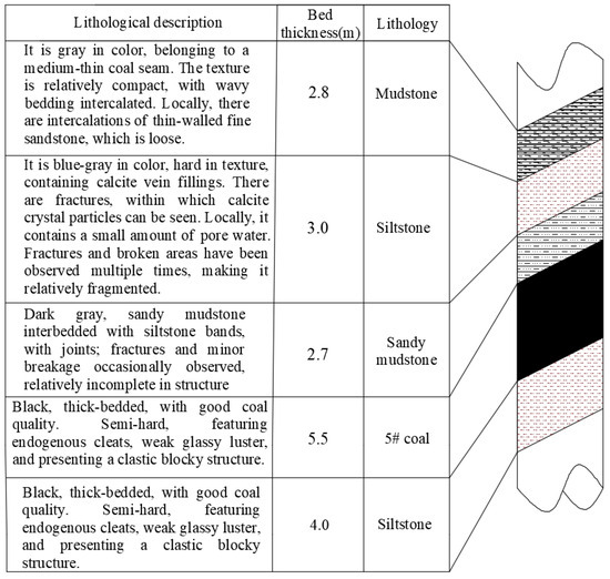
Figure 1.
Rock structure drilling column chart of 1502 level roadway in Dayuan Coal Industry.
Field investigations found that the 1502 level roadway in the Dayuan Coal Industry and its adjacent roadways exhibit the following main characteristics (as shown in Figure 2):
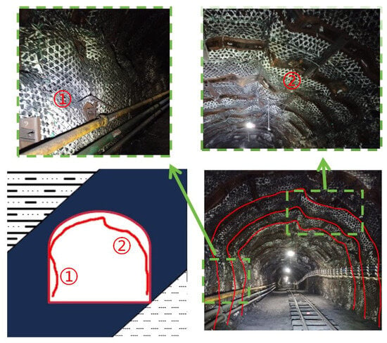
Figure 2.
Asymmetric deformation of roadway.
- (1)
- Obvious asymmetric deformation and failure occur in the roadway roof and sidewalls. The deformation of the lower side of the roadway is significantly greater than that of the upper side, and the deformation of the upper side of the roof is significantly greater than that of the lower side.
- (2)
- There are localized anchor bolt failures at the middle position of the lower side of the roadway and the roof on the upper side (where the roadway deformation is the largest).
3. Deformation and Failure Characteristics and Selection of Surrounding Rock in Roadways with Different Cross-Sectional Shapes
Through investigations on the Dayuan Coal Industry and adjacent steeply inclined coal seam mines, it was found that the main cross-sectional shapes of roadways used are arch, rectangular, and inclined roof trapezoidal sections. Therefore, the influence of the above three roadway cross-sectional shapes on the asymmetric deformation of steeply inclined thick coal seam roadways is explored through a mechanical analysis and numerical simulation, and the optimal roadway cross-sectional shape is selected.
3.1. Mechanical Analysis of Roadway Roof with Different Cross-Sections
To investigate the impact of roadway cross-section shapes on the asymmetric deformation of roadways in steeply inclined thick coal seams and to determine the optimal cross-section shape, the applicability of three typical roadway cross-section configurations is analyzed through a mechanical analysis. Due to the asymmetric stress distribution in steeply inclined coal seam roadways, the load forms acting on the surrounding rock may vary significantly. To generalize the fundamental principles, the loading conditions are simplified as a uniformly distributed load to approximately represent the stress state of the roadway.
3.1.1. Force Analysis of Arch Roadway Roof
The roof boundary of the three-center arch cross-sectional roadway is composed of three tangent arcs. The self-weight load of the overlying rock is simplified as a uniform vertical stress q applied to the top of arch cross-sectional roadway, where q = γH (unit: MPa) γ is the unit weight of the overlying rock (unit: kN·m−3) and H is the burial depth of the roadway, taken as 330 m. The stress distribution on the arch cross-sectional roadway is shown in Figure 3.
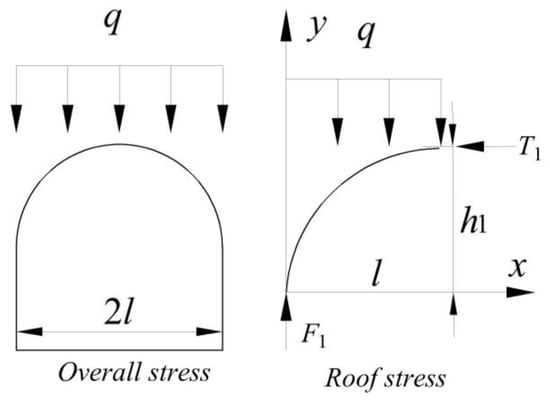
Figure 3.
Stress distribution schematic diagram of the roof of a roadway with an arched section.
According to the force balance principle, it can be obtained [24]:
where F1 is the vertical force acting on the straight wall above the arch cross-sectional roadway, T1 is the horizontal force acting on the midpoint of the roof, l is half the roadway width (the three roadway cross-sections share the same width and equal cross-sectional area to minimize size discrepancies), and h1 is the arch height of the roadway (m).
From Equation (1), the calculation shows the following [24]:
where h1 is the arch height (m), q is the vertical stress (q = γH, MPa), H is the burial depth of the roadway roof (m), and γ is the unit weight of the overlying rock (kN/m3).
3.1.2. Force Analysis of Rectangular Roadway Roof
The roof boundary of the rectangular cross-sectional roadway can be regarded as a horizontal straight line, and the self-weight load of the overlying rock is idealized as a uniform vertical stress q applied to the top of the rectangular cross-sectional roadway. The stress distribution on the rectangular cross-sectional roadway is shown in Figure 4.
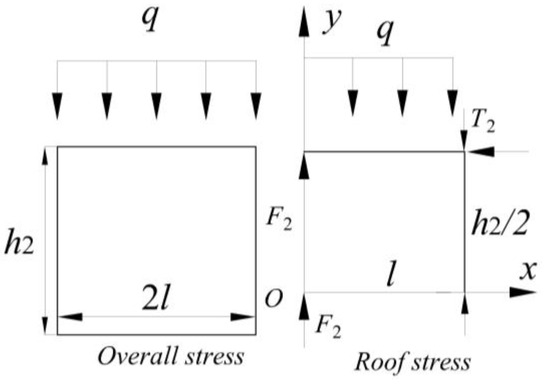
Figure 4.
Stress distribution schematic diagram of the roof of a roadway with a rectangular section.
According to the force balance principle, it can be obtained:
where F2 is the vertical force acting on the shoulder corner of the rectangular cross-sectional roadway, T2 is the horizontal force acting on the roof, and h2 is the roadway height (m).
From Equation (3), the calculation shows the following:
3.1.3. Force Analysis of the Inclined Trapezoidal Section Roadway Roof
The roof of the inclined roof trapezoidal cross-sectional roadway is generally excavated along the stable bedding of coal and rock layers, and the roof boundary is idealized as an inclined straight line. The self-weight load of the overlying rock is idealized as a uniform vertical stress q applied to the top of the inclined roof trapezoidal cross-sectional roadway. The stress distribution on the inclined roof trapezoidal cross-sectional roadway is shown in Figure 5.
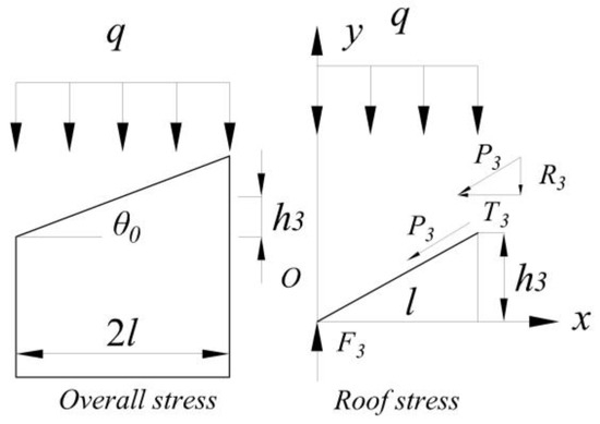
Figure 5.
Stress distribution schematic diagram of the roof of a roadway with an inclined roof trapezoidal section.
According to the force balance principle, it can be obtained [24]:
where F3 is the vertical force acting on the left shoulder corner, P3 is the interlayer shear force acting on the right shoulder corner position, R3 is the vertical component of this shear force, T3 is the horizontal component, θ0 is the inclination angle of the roadway roof, taken as the coal seam dip angle (°), and h3 is half of the height difference between the left and right corners of the roadway, defined as h3 = l × tanθ0(m).
From Equation (5), the calculation shows the following [24]:
Summarizing Equations (2), (4), and (6), the force calculation results of roadways with different cross-sections are presented in Table 1.

Table 1.
Calculation results of stress on roadways with different cross-sections.
First, comparing the vertical bearing capacity of roadways with three cross-sectional shapes, it is evident that F3 > F2 = F1, that is, the vertical force borne by the inclined roof trapezoidal roadway is significantly greater than that of the arch and rectangular roadways.
Further, in terms of the horizontal force, under the condition of a steeply inclined coal seam, as the dip angle θ of the inclined roof trapezoidal roadway roof increases, P3 > T1 and P3 > T2 occur; the magnitude relationship between T1 (horizontal force in the rectangular roadway) and T2 (horizontal force in the arch roadway) is related to the arch rise height and arch height of the arch roadway, requiring further analysis. Here, it is assumed that the cross-sectional areas of the constructed arch and rectangular roadways are equal, that is
where S1 is the cross-sectional area of the arch section, S1 = lh0 + 0.262l2 [25]; h0 is the arch rise height; and S2 is the cross-sectional area of the rectangular section, S2 = lh2.
Then,
Therefore,
3.2. Analysis of Deformation and Failure of Roadways with Different Cross-Sectional Shapes
3.2.1. Establishment of Numerical Model
To further study the stability of roadways in steeply inclined thick coal seams with different cross-sectional shapes, based on the geological surrounding rock column diagram of the 1502 transportation gateway, a finite element mesh model with tetrahedron-based elements was established using RHINO, and simulated calculations were performed using FLAC3D. Since the 1502 transportation gateway is a mine district main roadway generally arranged in areas with stable geological conditions, only the deformation and failure of the roadway surrounding the rock after roadway excavation were simulated, without considering the influence of geological structures, mining-induced effects, etc., on roadway stability. Therefore, the model size was set as 50 m × 50 m × 50 m. The numerical model of the arched cross-section roadway is shown in Figure 6, which contains 439,274 zones and 96,762 gridpoints (numerical simulation studies conducted with this model size are sufficient to avoid the influence of boundary effects on the roadway surrounding rock [16,24]).
Figure 6.
Numerical model of arched section roadway.
The physicomechanical parameters of the roof and floor of the 1502 level roadway are used for the coal and rock properties of the roadway surrounding rock (see Table 2). The Mohr–Coulomb elastoplastic criterion based on elastoplastic theory is adopted in the simulation. Considering the self-weight of the overlying rock, a uniform vertical stress of γH = 25 kN·m−3 × 280 m = 7.0 MPa is applied to the top boundary of the model, and the lateral boundaries and bottom of the model are set as fixed constraints. Taking the influence of roadway cross-sectional dimensions into account, the dimensional parameters of the arched cross-section are adopted from those used in the engineering site, with different cross-sectional shapes maintaining an equal width and equal cross-sectional area.
Table 2.
1502 level roadway roof and floor physical and mechanical parameters.
3.2.2. Analysis of Numerical Simulation Results
As shown in Figure 7, the plastic zones of the surrounding rock of the three cross-sectional shape roadways exhibit pronounced asymmetry. At the same time, affected by the differences in cross-sectional shapes and roadway bearing characteristics, large-area shear failures occur at the lower part of the lower side and the roof on the upper side, and the plastic zone range and depth reach the maximum at different positions of the sidewalls. The inclined-roof trapezoidal section exhibits the largest plastic zone area. Although the inclined roof conforms to the coal seam dip angle to reduce the shear effect between coal bedding planes, due to stress concentration, large-area plastic deformation and failure occur at the shoulder corners, with a maximum failure depth of 2.1 m, and more serious tensile failure occurs in the side roof under the condition of a larger roof length. The rectangular section ranks second in the plastic zone area. Under the combined action of shear slip between coal bedding planes and stress concentration, serious shear failures occur near the lower part of the lower side of the roadway and the shoulder corner of the upper side, with maximum failure depths of 1.5 m and 1.8 m, respectively. The arched section displays the smallest plastic zone area. Shear failures are mainly concentrated in the lower part of the lower side and the arching position of the upper side roof, with a maximum failure depth of 1.2 m.
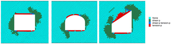
Figure 7.
Plastic zone state of roadway surrounding rock with three types cross-sectional shapes in steep seam.
In summary, under the mining conditions of steeply inclined thick coal seams, the three roadway cross-sectional shapes have their own characteristics.
For the rectangular cross-section, it exhibits moderate overall stress distribution. Its most significant advantage lies in the ease of roadway formation and simple construction technology, as it requires no complex contour control or curved surface support. This can significantly reduce the technical difficulty of tunneling and construction costs, making it particularly suitable for engineering scenarios with high requirements for tunneling speed. However, this cross-sectional form has application limitations: due to its geometric shape, the rectangular cross-section forms a typical stress-concentration area at the shoulder angle (the junction between the roof and sidewalls). This phenomenon originates from the action of asymmetric surrounding rock stress—after roadway excavation, sudden changes in boundary conditions at the shoulder angle cause stress redistribution, where vertical and horizontal stresses overlap to form stress peaks higher than those in the surrounding rock mass. If the surrounding rock is of low strength or poor integrity, stress concentration at the shoulder angle is prone to induce local rib spalling, roof collapse, and other instability phenomena. This stress-concentration effect becomes more severe in high-ground-stress environments or areas with large rock layer dips. Therefore, this cross-section is suitable for roadway projects with simple geological conditions (e.g., near-horizontal strata, good rock integrity), mild stress environments, and priority given to construction efficiency.
For the arched cross-section, a mechanical analysis shows that the arched cross-section has the optimal stress distribution characteristics, with significantly lower stress concentration coefficients in the vault and arch shoulder areas compared to other cross-sectional forms. This mechanical advantage stems from the axial load-bearing characteristics of the arched structure, which can effectively mobilize the self-supporting capacity of the surrounding rock and reduce the load on the support structure. In steeply inclined thick coal seams (coal seam thickness > 3.5 m or coal seam thickness > roadway height) where the entire cross-section is located in soft coal (uniaxial compressive strength ≤ 15 MPa), the arched cross-section can significantly improve the stress state of the surrounding rock and exhibit good engineering adaptability. However, this cross-sectional form also has limitations: when the coal seam thickness is <3.5 m, part of the cross-section may be located at the coal–rock interface, where shear slip failure is prone to occur due to interlayer shearing action. In addition, when the excavation direction changes or the burial depth increases, the arch shape may lose its advantages over other cross-sectional shapes. Based on numerical simulation studies and numerous research results, combined with the specific engineering conditions of the 1502 level roadway (steeply inclined thick coal seam, soft coal occurrence), the arched cross-section was ultimately determined to be the optimal form
For the inclined roof trapezoidal cross-section, the roadway roof of the inclined roof trapezoidal cross-section is excavated along the coal seam bedding, preserving the original bedding structure of the coal seam, and the inclined roof structure conforms to the force of the inclined coal–rock layers. This structural feature brings significant mechanical advantages: it can suppress the generation of interlayer shearing action and effectively control the deformation of both sidewalls. However, this cross-sectional form has application limitations: it requires stable bedding within the coal seam as a precondition, and the longer roof is more prone to failure, resulting in lower cross-sectional utilization. In terms of the stress-distribution characteristics, significant stress concentration occurs at the corner angles of the sidewalls, triggering stress field redistribution in the ribs—stress decreases in the upper rib and increases in the lower rib. The specific mechanism is as follows: due to the smooth bedding planes, shear stress redistribution under gravitational force in the lower rib coal body causes the failure mode to shift from slip failure to shear deformation. While this enhances the local bearing capacity, it leads to deep expansion of the plastic zone. The upper rib coal-rock, driven by continuous gravitational component forces, accumulates slip potential energy along bedding planes, making it prone to coal body instability and (sliding collapse), which can trigger surrounding rock failure. Therefore, the inclined roof right trapezoidal cross-section is suitable for thin and medium-thick coal seams (0–3.5 m) excavated along the roof.
4. Deformation and Failure Mechanism of Surrounding Rock in Roadways Under Different Coal Seam Dip Angles
For steeply inclined thick coal seam roadways, in addition to the roadway cross-sectional shape, the coal seam dip angle is also an important factor affecting roadway deformation and failure. Numerical simulation models of arched roadways with coal seam dip angles of 0°, 10°, 20°, and 30° were established. Except for the coal seam dip angle and related strata structural changes caused by the dip angle variation, all other model parameters are consistent with those of the arched roadway numerical simulation model with a coal seam dip angle of 42°. A comparative analysis is now conducted on the surrounding rock stress distribution and plastic deformation failure of roadways under the conditions of coal seam dip angles of 0°, 10°, 20°, 30°, and 42°.
4.1. Stress Distribution State Analysis
As shown in Figure 8, the vertical stress concentration area gradually shifts along the direction of the coal seam dip angle, and the deflection direction is almost consistent with the inclined direction of the coal seam. When the coal seam dip angle θ ≤ 20°, the maximum vertical stress value is about 16 MPa, close to the vertical stress peak of near-horizontal coal seam roadways. As θ ≥ 20°, not only does the vertical stress concentration area deflect, but the vertical stress on the two sides of the roadway also begins to decrease. When θ = 42°, the maximum vertical stress on the lower side of the roadway is 15.08 MPa, and on the upper side is 12.96 MPa, which are 6% and 19% lower, respectively, compared with the dip angle of 20°. The ratios of the difference between the horizontal stress peak and the stress at the symmetric position to the peak under coal seam dip angles of 0°, 10°, 20°, 30°, and 42° are 0.013, 0.057, 0.098, 0.244, and 0.417 in sequence.
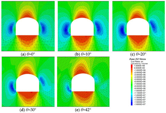
Figure 8.
Vertical stress state of arched roadway under different coal seam inclination angles.
As shown in Figure 9, the original horizontal stress concentration area gradually shifts along the direction of the coal seam dip angle, and the deflection direction is closely aligned with the inclined direction of the coal seam. At the same time, the horizontal stress at the arch crown of the inferior side roof and the bottom of the lower side of the roadway gradually increases, forming a new stress concentration area. When θ = 42°, the maximum horizontal stress on the inferior sidewall is 8.31 MPa, and on the superior side roof, it is 9.35 MPa. The ratios of the difference between the horizontal stress peak and the stress at the symmetric position to the peak under coal seam dip angles of 0°, 10°, 20°, 30°, and 42° are 0.005, 0.154, 0.402, 0.524, and 0.698 respectively.
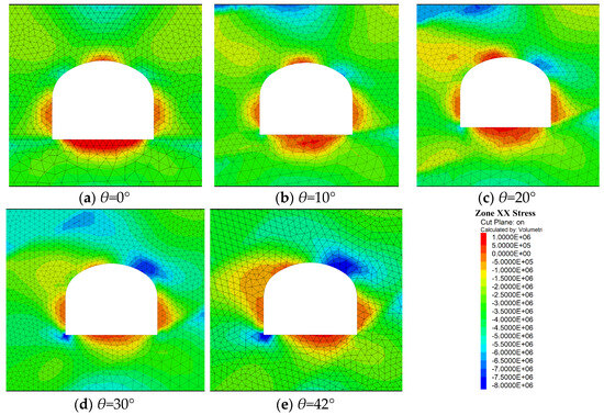
Figure 9.
Horizontal stress state of arched roadway under different coal seam inclination angles.
4.2. Plastic Zone Distribution State Analysis
As shown in Figure 10, the plastic zone of the roadway surrounding the rock exhibits pronounced asymmetry, with the development of the plastic zone dominated by shear failure. The plastic zone of shear failure gradually deflects along the direction of the coal seam dip angle, and the deflection direction is almost consistent with the deflection direction of the stress concentration area. At a coal seam dip angle of 42°, extensive shear failures occur at the lower portion of the inferior sidewall and the arch crown of the inferior side roof, with a maximum failure depth of 1.2 m.
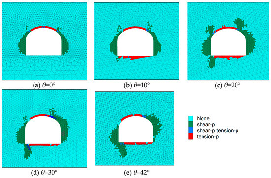
Figure 10.
Plastic zone state of surrounding rock in arched roadway under different coal seam inclination angles.
In summary, the stress-concentration zones of the surrounding rock in the arch roadway migrate along the inclined direction of the coal seam, and the degree of asymmetry increases with asymmetry intensifying with the coal seam dip angle. Concurrently, stress accumulates in the superior side roof and inferior sidewall base, creating asymmetric stress-concentration zones. The plastic zone formed by shear failure due to stress concentration also deflects with the increase in the coal seam dip angle, and the deflection mode is consistent with that of the stress-concentration area, leading to widespread shear failures on the roof of the upper side and the lower part of the lower side of the roadway, forming the asymmetric deformation and failure of steeply inclined coal seam roadways. Thus, an asymmetric support scheme needs to be implemented, that is, strengthening the support for the roof of the upper side and the lower part of the lower side of the roadway.
5. Asymmetric Support Technology and Industrial Experiment
5.1. Asymmetric Support Technology
The roadway section of the 1502 transportation roadway is a three-centered arch section with a width of 4.2 m, a height of 3.3 m, and a springing height of 1.8 m. Based on the existing symmetric support scheme for 1501 and the study on the asymmetric stress distribution and deformation failure law of surrounding rock in large-dip thick coal seam roadways, asymmetric support parameters were proposed. The deformation of the surrounding rock under different support schemes was simulated, and the plastic zone area was statistically analyzed. The parameters of each support scheme are summarized in Table 3, and the plastic zones of surrounding rock under different support schemes are shown in Figure 11.
Table 3.
Summary of parameters for different support schemes.
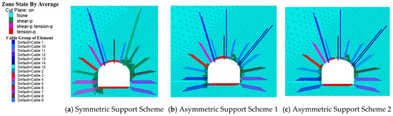
Figure 11.
Plastic zones of surrounding rock under different support schemes.
By comparing the plastic zone areas of different support schemes with corrected data, the plastic zone area of Asymmetric Support Scheme 2 is the smallest (89 grid cells), significantly reduced by 32.6% compared to the Symmetric Support Scheme (246 grid cells) and by 15.2% compared to Asymmetric Support Scheme 1 (105 grid cells). This demonstrates that Asymmetric Support Scheme 2 exhibits the strongest ability to suppress plastic deformation development in the surrounding rock, optimize the stress distribution, and enhance roadway stability. Therefore, based on the superior control effect on plastic zone expansion and engineering safety requirements, Asymmetric Support Scheme 2 is confirmed as the final support scheme for the 1502 transportation roadway.Therefore, considering the control effect on the plastic zone and engineering safety, Asymmetric Support Scheme 2 is selected as the final support scheme for the 1502 transportation roadway.The support diagram of the final asymmetric support scheme is shown in Figure 12.
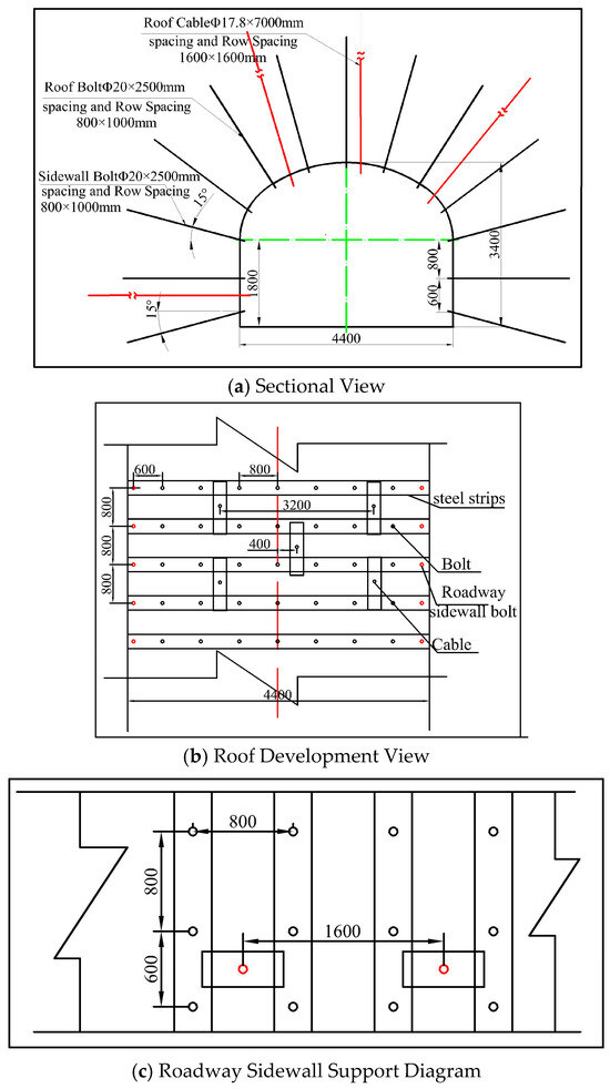
Figure 12.
Section of 1502 level roadway support.
As shown in Figure 12, the bolts are Φ20-M22-2400 mm full-thread steel equal-strength bolts. The row spacing between the roof and the upper side is 800 mm × 800 mm, and that in the lower side is 600 mm × 800 mm. The bolts are connected by W steel strips. The anchor mesh uses 5.0 m × 1.0 m diamond mesh and 10.0 m × 1.0 m double-anti plastic mesh. The cables compriseΦ17.8 mm low-relaxation pre-stressed steel strands, arranged in a 2-1-2 pattern, with a row spacing of 1200 mm × 800 mm. The cable trays are replaced with 1.2 m 25U steel bearers.
5.2. Industrial Experiment
As shown in Figure 13, during the excavation of the 1502 level roadway, regular observations of convergence of both sides and roof-floor were carried out using the “cross-measurement point method” at each 50 m measuring station along the roadway to monitor the relative deformation of the roadway. Fixed holes were drilled at the midpoint of the roof and floor in the vertical direction and at the midline of the straight wall, and wooden stakes were driven into the holes for marking. During the observation, the distances between A and B and between C and D were measured. The change in the distance between C and D represents the roof-floor convergence, while the change in the distance between A and B represents the sidewall convergence.
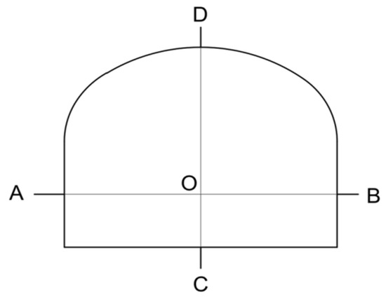
Figure 13.
Schematic diagram of roadway surface observation.
During the test in the 1502 level roadway, measuring points were set to observe the deformation of the roadway-surrounding rock (Figure 14). In the early stage of excavation, the deformation rate of the surrounding rock was rapid; as time went on, the deformation rate gradually decreased, and the deformation amount stabilized 20 days after roadway excavation. On the whole, the deformation of the roadway roof is larger than that of the sidewalls. The maximum roof deformation before and after the support scheme optimization is 366 mm and 197 mm, respectively, representing a 46.17% reduction. The maximum sidewall deformation before and after optimization reached 303 mm and 167 mm respectively, representing a 44.88% reduction. The deformation of the optimized roadway is within the controllable range.
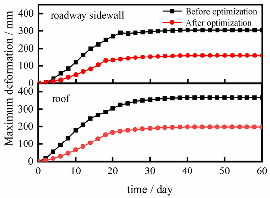
Figure 14.
Elastic curve of surrounding rock in 1502 level roadway.
6. Discussion
In the preceding analysis, the adaptability of mine main roadways with different cross-sectional shapes under uniform load conditions was investigated. It was found that in steeply inclined coal seams with a thickness greater than 3.5 m, arched roadways exhibit significant advantages over rectangular and inclined-roof trapezoidal (e.g., right trapezoidal with inclined roof) sections. Meanwhile, it should be noted that for seam thicknesses less than 3.5 m, the conclusions of Zhang, Z.Y. [26] and Qi, X.Y. [27] may be more applicable, i.e., inclined-roof trapezoidal sections show better adaptability.
Subsequently, the influence of the coal seam dip angle on roadway stability was explored. It was revealed that with an increasing dip angle, roadways exhibit a significant asymmetric failure distribution, consistent with the findings of Hao [28] and Chi [29]. However, this study differs in identifying that as the coal seam dip angle increases, obvious stress-concentration zones form at the arch shoulder of the upper rib and the wall base of the lower rib, leading to asymmetric deformation and failure. Concurrently, the peak horizontal stress in these zones gradually increases, while the peak vertical stress decreases, which is likely related to the deflection of principal stress directions. In the context of this study’s extra-thick coal seam, the failure mode of the surrounding rock may transition from tensile failure to shear failure. Based on these insights, an innovative asymmetric support technology for thick coal seams was proposed and achieved good engineering performance.
Generally, in steeply inclined thick coal seam roadways, uniform support schemes based on symmetric cross-sectional shapes (such as rectangular and arched sections) are adopted, with high-strength bolt-mesh-cable systems used to improve overall support strength and maintain surrounding rock stability. The advantage of such symmetric schemes lies in their construction convenience, but they often result in over-support in areas with relatively small deformation. By contrast, the new technology applied in the test roadway avoids this issue, optimizing support efficiency and reducing unnecessary material consumption.
7. Conclusions
- (1)
- Influence of Roadway Cross-Section Shapes on Surrounding Rock Stability
The stress distribution and plastic zone extent in the surrounding rock of three typical cross-sections (inclined roof trapezoidal, rectangular, and arched) exhibit a descending order: inclined roof trapezoidal section > rectangular section > arched section. The arched section demonstrates the smallest plastic zone area (maximum failure depth of 1.2 m), reducing it by 42.9% compared to the inclined roof trapezoidal section, indicating its optimal stress distribution and self-bearing capacity.
Limitations: The arched section is prone to interlayer shear slip failure when the coal seam thickness is <3.5 m (crossing the coal-rock interface). The inclined roof trapezoidal section, while reducing shear along bedding planes, suffers from long roof span instability and severe corner stress concentration (plastic zone depth up to 2.1 m), making it suitable only for thin coal seams (≤3.5 m) with stable bedding.
Optimal Selection: For steeply inclined thick coal seams (thickness 5.5 m, dip angle 42°), the arched cross-section is confirmed as the best choice, effectively suppressing stress concentration and plastic zone expansion in soft coal strata thicker than the roadway height.
- (2)
- Deformation Mechanism Induced by Coal Seam Dip Angle
As the coal seam dip angle increases (0°~42°), stress-concentration areas deflect along the dip direction, with the lower sidewall foundation and upper sidewall arch shoulder becoming primary stress centers. When the dip angle is ≥20°, vertical stress peaks decrease by 6–19%, but the horizontal stress asymmetry coefficient increases to 0.698, exacerbating non-uniform stress states.
Failure Mode: Stress concentration triggers shear failure, with plastic zones expanding along the dip direction. The lower sidewall experiences shear failure up to 1.2 m in depth, while the upper sidewall roof undergoes tensile-shear composite failure, forming a diagonal failure zone (“upper roof–lower sidewall”).
Driving Force: The non-symmetric deformation is fundamentally driven by the coupling of inclined stratum stress fields and roadway geometry, necessitating targeted reinforcement in stress-concentrated areas.
- (3)
- Effectiveness of Asymmetric Support Technology
Optimized Support Scheme: The “dip-oriented reinforcement” asymmetric support scheme (Scheme 2) features the following:
Roof bolt spacing reduced to 800 mm × 800 mm, with cables arranged in a “2-1-2” pattern (spacing 1600 mm × 800 mm);
Inclined reinforcing cables added to the lower sidewall (spacing 1600 mm) to strengthen shear-prone zones.
Numerical simulations show that Scheme 2 reduces the plastic zone area to 89 grid cells, a 32.6% decrease compared to symmetric support and 15.2% compared to Asymmetric Scheme 1, demonstrating superior stress optimization.
Field Validation: After implementation in the 1502 roadway, roof-floor convergence decreased from 366 mm to 197 mm (46.17% reduction), and sidewall convergence decreased from 303 mm to 167 mm (44.88% reduction), confirming the scheme’s effectiveness in controlling deformation within safe limits.
- (4)
- Future Research Directions
Further studies should investigate the coupled effects of mining-induced stress, hydrogeological conditions, and dynamic loading on roadway stability and develop intelligent dynamic support systems for complex mining environments.
Author Contributions
F.L.: Writing-original draft, Data Curation, Formal analysis, Investigation. B.Z.: Funding acquisition, Methodology, Supervision, Project administration. J.G.: Funding acquisition, Methodology, Conceptualization, Writing—review and editing. Z.L.: Writing—review and editing, Data curation, Validation. Y.X.: Writing-review and editing. Q.X.: Methodology. D.D.: Funding acquisition. All authors have read and agreed to the published version of the manuscript.
Funding
This work was financially supported by the National Natural Science Foundation of China (52474139) and the Fundamental Research Program of Shanxi Province (202403011242005, 20210302123148).
Institutional Review Board Statement
Not applicable.
Informed Consent Statement
Not applicable.
Data Availability Statement
Data to support the findings of this study are available from the first author upon request.
Conflicts of Interest
The authors declare no conflicts of interest.
References
- Wu, Y.P.; Yun, D.F.; Xie, P.S.; Wang, H.; Lang, D.; Hu, B. Progress practice and scientific issues in steeply dipping coal seams fully-mechanized mining. J. China Coal Soc. 2020, 45, 24–34. [Google Scholar] [CrossRef]
- Kang, H.P.; Xu, G.; Wang, B.M.; Wu, Y.Z.; Jiang, P.F.; Pan, J.F.; Ren, H.W.; Zhang, Y.J.; Pang, Y.H. Forty years development and prospects of underground coal mining and strata control technologies in China. J. Min. Strat. Control Eng. 2019, 1, 013501. [Google Scholar] [CrossRef]
- Hu, B.S.; Xie, P.S.; Huang, B.F.; Wu, Y.P.; Chen, J.J. Study on Roof Breaking Mechanism and Support Stability of Steeply Dipping Seam and Large Mining Height. Energy Explor. Exploit. 2024, 4, 544–566. [Google Scholar] [CrossRef]
- Yin, Y.C.; Zhao, T.B.; Zhang, Y.D.; Tan, Y.L.; Qiu, Y.; Taheri, A.; Jing, Y. An Innovative Method for Placement of Gangue Backfilling Material in Steep Underground Coal Mines. Minerals 2019, 9, 107. [Google Scholar] [CrossRef]
- Wu, Y.P.; Liu, K.Z.; Yun, D.F.; Jie, P.D.; Wang, G.W. Research progress on the safe and efficient mining technology of steeply dipping seam. J. China Coal Soc. 2014, 39, 1611–1618. [Google Scholar] [CrossRef]
- Tu, H.S.; Tu, S.H.; Yuan, Y.; Wang, F.T.; Bai, Q.S. Present situation of fully mechanized mining technology for steeply inclined coal seams in China. Arab. J. Geosci. 2015, 8, 4485–4494. [Google Scholar] [CrossRef]
- Zhang, J.; Wang, J.; Wei, W.; Chen, Y.; Song, Z. Experimental and numerical investigation on coal drawing from thick steep seam with longwall top coal caving mining. Arab. J. Geosci. 2018, 11, 96. [Google Scholar] [CrossRef]
- Pan, W.P.; Li, H.B.; Hua, X.Z.; Liu, B.; Li, C. Research on Grouting Reinforcement Technology of Fault Crossing Roadway in Fully Mechanized Mining Face with Large Dip Angle. Bull. Eng. Geol. Environ. 2024, 83, 216. [Google Scholar] [CrossRef]
- Cao, X.Q.; Ma, L.Q.; Yang, M.F.; Chen, F. Face End Support and Advance Support Technology in High Inclined Seam. Coal Sci. Technol. 2012, 40, 1–4. [Google Scholar] [CrossRef]
- Lv, W.Y.; Wu, Y.P.; Ming, L.; Yin, J.H. Migration Law of the Roof of a Composited Backfilling Longwall Face in a Steeply Dipping Coal Seam. Minerals 2019, 9, 188. [Google Scholar] [CrossRef]
- Wang, Y.; Tang, J.; Dai, Z.; Yi, T.; Li, X. Flexible roadway protection technology in medium-thickness coal seam with large dip angle. Energy Sources Part A Recovery Util. Environ. Eff. 2018, 41, 3085–3102. [Google Scholar] [CrossRef]
- Han, Z.P.; Dou, L.M.; Wang, Z.Y.; Qiao, Z.D. Research on stress distribution law of two ribs in large dip angle working face under influence of dynamic and static loads. Coal Sci. Technol. 2019, 47, 183–188. [Google Scholar] [CrossRef]
- Zhao, X.Z.; Wang, C.G.; Zhou, K.Y.; Guo, L.; Zhang, J.; Li, Y.P.; Zhang, W.; Sun, X.Q. Geo-dynamic conditions instability and support optimization of semi coal–rock roadway in large inclined and extra thick coal seam. Coal Sci. Technol. 2022, 50, 20–29. [Google Scholar] [CrossRef]
- Xin, Y.J.; Gou, P.F.; Yun, D.F.; Liu, H.Y. Instability characteristics and support analysis on surrounding rock of soft rock gateway in high-pitched seam. J. Min. Saf. Eng. 2012, 29, 637–643. [Google Scholar]
- Xiong, X.Y.; Dai, J. Research on support technology of right angle trapezoidal roadway in generally inclined coal seam. J. China Coal Soc. 2020, 45, 110–118. [Google Scholar] [CrossRef]
- Zhang, J.P.; Liu, L.M.; Liu, C.X.; Zhao, Y.P.; Sun, D.L.; Shao, J. Cross-section shape and coupling support of deep and large-inclined coal and rock roadway. J. Cent. South Univ. (Sci. Technol.) 2021, 52, 4074–4087. [Google Scholar] [CrossRef]
- Liu, H.L.; Xu, C.; Wang, H.Z.; Li, G.D.; Fan, S.Y. Investigation on Surrounding Rock Stability Control Technology of High Stress Roadway in Steeply Dipping Coal Seam. Adv. Civ. Eng. 2021, 2021, 5269716. [Google Scholar] [CrossRef]
- Xie, Z.Z.; Wang, J.; Zhang, N.; Guo, F.; He, Z.; Xiang, Z.; Zhang, C.H. Study on Time-Dependent Failure Mechanisms and CBAG Differential Support Technology of Roadway in Steeply Inclined Coal Seam. Processes 2023, 11, 866. [Google Scholar] [CrossRef]
- Yang, H.Y.; Cao, S.G.; Li, Y.; Sun, C.M.; Guo, P. Soft Roof Failure Mechanism and Supporting Method for Gob-Side Entry Retaining. Minerals 2015, 5, 707–722. [Google Scholar] [CrossRef]
- Chen, J.Q.; Yan, R.B.; Liu, K.L. Asymmetric deformation mechanism of roadway at steeply inclined thick coal seam. J. China Coal Soc. 2018, 43, 3007–3015. [Google Scholar] [CrossRef]
- Zhang, B.; Cao, S.G.; Wang, L.G.; Lu, Y.L. Deformation failure mechanism and support measurements in roadway of steeply inclined coal seam. J. Min. Saf. Eng. 2011, 28, 214–219. [Google Scholar]
- Hao, Y.; Wu, Y.; Chen, Y.L.; Li, P.; Chen, L.; Zhang, K. An innovative equivalent width supporting technology for sustaining large-cross section roadway in thick coal seam. Arab. J. Geosci. 2019, 12, 688. [Google Scholar] [CrossRef]
- Wang, X.F.; Wang, Y.; Zhang, D.S. Enhanced support technology for key area of the roadway in large inclined angle “three-soft” coal seam. J. Min. Saf. Eng. 2017, 34, 208–213. [Google Scholar] [CrossRef]
- Pan, K.; Ju, W.J.; Wang, J.C.; Zhang, Z. Optimization of cross-sectional shape and support parameters of headgate in fully mechanized coal seam with large dip angle and close distance. Coal Sci. Technol. 2024, 52, 12–22. [Google Scholar] [CrossRef]
- Li, Y.X.; Yao, C. Collapse Mechanism of Deep Tunnels with Three-Centered Arch Cross Section. J. Cent. South. Univ. 2016, 23, 3293–3301. [Google Scholar] [CrossRef]
- Zhang, Z.Y.; Zhang, W. Research on the Deformation Characteristics and Support Methods of the Cross-Mining Roadway Floor Influence by Right-Angle Trapezoidal Slope. Geomech. Eng. 2024, 37, 293–306. [Google Scholar] [CrossRef]
- Qi, X.Y.; Wang, R.J.; Mi, W.T. Failure Characteristics and Control Technology of Surrounding Rock in Deep Coal Seam Roadway with Large Dip Angle under the Influence of Weak Structural Plane. Adv. Civ. Eng. 2020, 2020, 6623159. [Google Scholar] [CrossRef]
- Hao, Y.; Liu, C.; Wu, Y.; Pu, H.; Zhang, K.; Shen, L. Analysis of Stress and Deformation on Surrounding Rock Mass of a Trapezoidal Roadway in a Large Inclination Coal Seam and Novel High Yielding Prop Support: A Case Study. Mathematic 2023, 11, 319. [Google Scholar] [CrossRef]
- Chi, X.L.; Yang, K.; Wei, Z. Breaking and mining-induced stress evolution of overlying strata in the working face of a steeply dipping coal seam. Int. J. Coal Sci. Technol. 2021, 8, 614–625. [Google Scholar] [CrossRef]
Disclaimer/Publisher’s Note: The statements, opinions and data contained in all publications are solely those of the individual author(s) and contributor(s) and not of MDPI and/or the editor(s). MDPI and/or the editor(s) disclaim responsibility for any injury to people or property resulting from any ideas, methods, instructions or products referred to in the content. |
© 2025 by the authors. Licensee MDPI, Basel, Switzerland. This article is an open access article distributed under the terms and conditions of the Creative Commons Attribution (CC BY) license (https://creativecommons.org/licenses/by/4.0/).