Article

Modeling and Control of Grid-Forming Active Power Filters for Harmonic Suppression and Enhanced Power Quality

1
Shenzhen Research Institute of Shandong University, Shenzhen 518063, China
2
School of Control Science and Engineering, Shandong University, Jinan 250100, China
*
Author to whom correspondence should be addressed.
Appl. Sci. 2025, 15(11), 5927; https://doi.org/10.3390/app15115927
Submission received: 23 April 2025 / Revised: 21 May 2025 / Accepted: 23 May 2025 / Published: 24 May 2025
(This article belongs to the Section Electrical, Electronics and Communications Engineering)

Abstract

Grid-forming converters (GFMCs) have gained significant attention for their functionality in grid voltage formation and grid-supportive services. However, managing harmonic distortions caused by nonlinear loads remains a critical challenge in weak grids. This paper presents a novel grid-forming active power filter (GFMC APF) that integrates voltage and frequency regulation with effective harmonic control. The proposed control method generates harmonic voltage commands by detecting voltage at the point of common coupling. The GFMC APF compensates harmonic voltages by creating a near short-circuit impedance path for harmonics, thereby preventing harmonic currents from propagating into the grid. In addition to improving harmonic performances, the system enhances grid stability by enhancing inertia, damping, and short-circuit capacity while suppressing wide-frequency oscillations. The proposed method avoids complex parameter tuning, ensuring simplicity and scalability. Simulation results validate the effectiveness of the GFMC APF in delivering precise harmonic control, improved power quality, and enhanced grid-forming capabilities.

1. Introduction

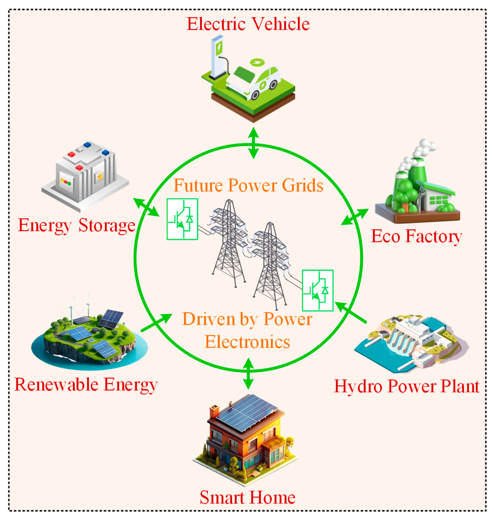
The increasing integration of renewable energy sources (RESs) and power electronics-based devices in modern power grids has significantly improved flexibility, efficiency, and environmental sustainability [1], as shown in Figure 1. The integration of RESs, such as solar and wind power, has enabled more decentralized and cleaner power generation, reducing dependence on fossil fuels and lowering carbon emissions [2]. Additionally, power electronics-based devices, such as inverters and converters, have enhanced grid flexibility by enabling more precise control over power flow, with recent advancements achieving up to 95% efficiency in high-power inverters [3]. However, this shift also introduces various technical challenges related to power quality and system stability [4]. Nonlinear loads, such as variable speed drives, rectifiers, and other power electronic devices, generate harmonic currents that distort the voltage waveform, with total harmonic distortion (THD) levels reaching as high as 30% in systems with significant nonlinear load penetration [5,6]. This harmonic distortion can lead to various issues, including transformer overheating, higher system losses, and interference with sensitive electronic equipment [7]. Furthermore, replacing traditional synchronous generators with RESs interfaced via voltage source converters has reduced system inertia, which plays a crucial role in damping frequency disturbances and ensuring stability in the grid [4]. This reduction in inertia increases the grid’s sensitivity to frequency deviations, particularly under sudden load changes or renewable generation variability, as discussed [8,9].
In recent years, significant advancements have been made in addressing these challenges. For instance, using advanced power electronic converters in RES integration has improved power quality, with multi-pulse rectifiers reducing harmonic distortions to below 5% in grid-connected photovoltaic (PV) systems [10]. Additionally, grid-connected PV systems employing Fractional Order Notch Filters (FNOFs) have demonstrated the ability to mitigate harmonic currents, achieving a THD reduction to 3.5% while compensating for reactive power and load unbalancing [11]. Moreover, the application of Unified Power Quality Conditioners (UPQCs) in PV–wind systems has successfully reduced THD from over 55% to below 2.23%, ensuring stable voltage and current levels under various operating conditions [12]. These advancements highlight the progress in managing power quality and stability issues in RES-dominated grids.
Conventional solutions, such as passive power filters, have been employed to mitigate harmonic distortions [13]. Passive filters are designed to attenuate specific harmonic frequencies, but they are often bulky, inflexible, and prone to resonance, making them unsuitable for dynamic systems where the harmonic spectrum can vary with load conditions. These systems also lack adaptability and cannot adjust to changing grid conditions, leading to inefficient performance when harmonic spectra vary with load [14]. On the other hand, active power filters (APFs) offer a more flexible, dynamic solution by compensating for harmonic currents in real time, achieving THD reductions to below 5% in grid-connected scenarios [15]. APFs can operate in both grid-connected and islanded modes, allowing them to adapt to varying grid conditions and load changes while providing more precise harmonic mitigation [16]. However, most APFs operate in grid-following mode, meaning they rely on an existing grid voltage for synchronization, making them dependent on grid stability and less effective in weak grids where voltage fluctuations exceed 10% [17,18]. While effective in mitigating harmonic currents, these systems cannot provide essential grid-supportive services, such as voltage regulation, frequency support, and enhanced damping, which are necessary in grids with high-RES penetration.
GFMCs have emerged as a promising solution to address the above-mentioned shortcomings. These converters enable direct control over grid voltage and frequency by emulating the dynamic behavior of conventional synchronous generators. This capability supports enhanced grid stability, particularly in low-inertia or weak grid environments. This capability allows them to provide essential grid-supportive services, such as voltage regulation and frequency control, even in islanded or weak grid conditions, as discussed in [19]. Unlike grid-following systems, GFMCs do not require phase-locked loops for synchronization, which makes them capable of operating independently in islanded conditions or weak grids, offering a more robust solution for modern power systems [20,21]. Despite their advantages, GFMCs have primarily focused on voltage and frequency regulation, while harmonic mitigation has not been fully integrated into their control strategies. This gap presents a significant challenge for modern power systems, as harmonic distortions remain a critical issue, especially in grids with high RES and nonlinear load penetration.
This paper proposes a novel GFMC APF that integrates the voltage and frequency control capabilities of GFMCs with advanced harmonic filtering to address the limitations of conventional APFs. The GFMC APF utilizes harmonic extraction from the PCC to generate precise harmonic voltage components, which are then used to generate compensating currents that reduce harmonic distortion and minimize disruptions in the system. The innovative control method of the GFMC APF ensures fast frequency and voltage regulation while enhancing grid stability by improving inertia, damping, and short-circuit capacity. This makes the system particularly effective in low-inertia grids where maintaining stability is more challenging, ensuring that the grid can effectively support increasing RES penetration without compromising power quality. The major contributions of this work are as follows:
(a)
Developing a GFMC APF control method that integrates grid-forming functionality with harmonic suppression to improve power quality in weak grids.
(b)
Proposing a precise harmonic extraction technique using PCC voltage measurements for accurate mitigation without affecting fundamental operations.
(c)
Designing a scalable and cost-effective control approach that eliminates complex parameter tuning, enabling seamless deployment in modern power systems.
The structure of this paper is as follows: Section 2 presents the GFMC APF system configuration, detailing its integration into the grid and harmonic mitigation components. 
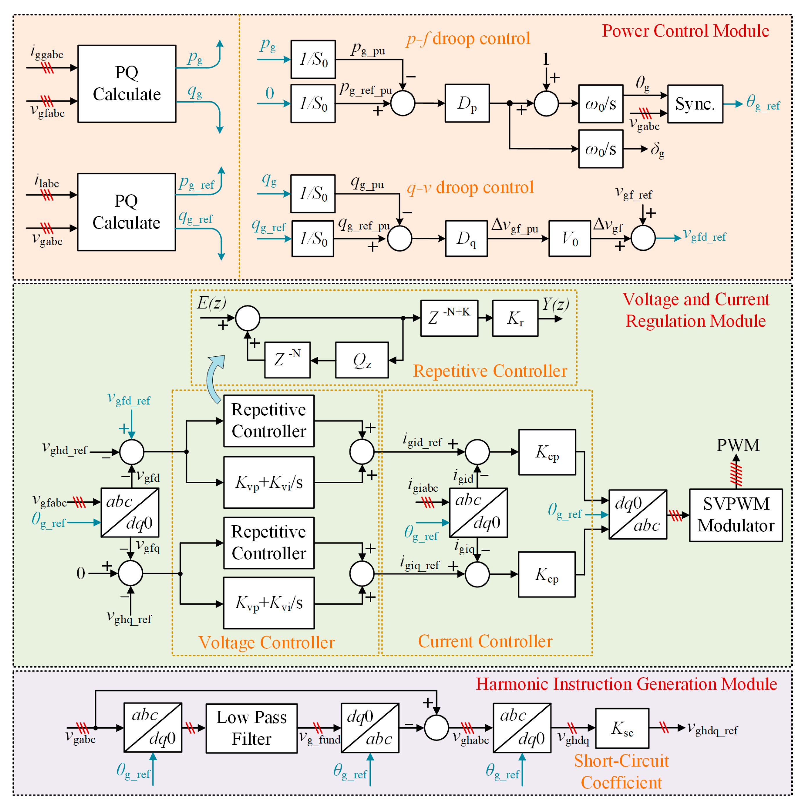
Section 3 describes the control structure, focusing on harmonic suppression and grid synchronization. Section 4 examines the stability analysis, focusing on controller tuning and its impact on system stability. Section 5 describes the harmonic compensation principle. Section 6 presents simulation results to demonstrate the effectiveness of the proposed method. Finally, Section 7 concludes the paper.

2. System Configuration

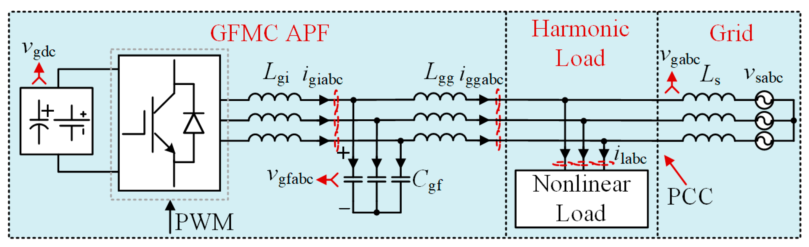
The schematic diagram in Figure 2 illustrates the GFMC APF system. The system is powered by a DC link, represented by vgdc, which could be a battery or another converter. The power electronics section consists of a GFMC controlled by pulse-width modulation (PWM) signals to generate the desired output. The interface between the converter and the grid is achieved through an LCL filter, comprising the converter-side inductor Lgi, the filter capacitor Cgf, and the grid-side inductor Lgg. The primary control objective is to regulate the capacitor voltages vgfabc to control the phase and magnitude of power injected into the grid. The nonlinear load, connected at the PCC, generates the harmonic currents ilabc, which the GFMC APF compensates for, ensuring harmonic-free grid-injected currents iggabc. The nonlinear load is modeled with an inductor Lload and a resistance Rload, representing its dynamic characteristics, and is configured as a three-phase diode bridge. The grid is defined as a series connection of grid inductors Ls and grid voltage sources vsabc. Voltages at the PCC, vgabc are measured for grid synchronization, and the injected power is regulated through the control of vgfabc. This setup ensures effective power transfer, grid synchronization, and harmonic suppression.

3. Control Structure

The control structure of the GFMC APF, as shown in Figure 3 and detailed below, comprises three modules: power control, voltage and current regulation, and harmonic instruction generation

3.1. Power Control Module

The power control module manages the active and reactive power exchange between the converter and the grid. It consists of two key components, an active power controller and a reactive power controller, both operating under a droop control strategy.
The active power controller regulates the converter’s synchronization with the grid by adjusting the reference angle θg. This adjustment is driven by the difference between the measured active power pg and the reference value pg_ref, which is typically set to zero to prioritize harmonic mitigation and reactive power support. The active power error, normalized by the system’s base power S0, is processed through a droop coefficient Dp. This coefficient determines the frequency deviation from the nominal grid frequency ω0 in response to power imbalances. The resulting frequency adjustment is integrated over time to compute θg, ensuring seamless synchronization with the grid. Mathematically, this relationship is expressed as
d δ g / d t = ω 0 D p ( p g / S 0 )
where δg represents the dynamic phase shift necessary to maintain grid stability during load variations.
The reactive power controller manages voltage regulation by adjusting the d-axis reference voltage vgfd_ref. It operates on a similar droop principle, where the reactive power error is normalized by S0 and scaled by the droop coefficient Dq. This generates a per-unit voltage deviation Δvgf_pu, which is converted to an actual voltage adjustment using the base voltage V0. The final d-axis reference voltage combines this deviation with the nominal grid voltage, allowing the converter to inject or absorb reactive power to support the voltage during grid disturbances such as sags or swells. The control equation for the d-axis reference voltage is given by
v gfd _ ref = V 0 D q ( q g _ ref / S 0 q g / S 0 ) + v gf _ ref
highlighting how the controller dynamically balances reactive power exchange while maintaining voltage stability.

3.2. Voltage and Current Regulation Module

This module ensures stable voltage and current control for the GFMC APF. The voltage controller combines a repetitive and proportional–integral (PI) controller to regulate vgfabc and suppress harmonics effectively. These capacitor voltages are transformed into the dq reference frame, and the harmonic voltage references (vghd_ref and vghq_ref) are generated from the harmonic voltage command, ensuring precise compensation of voltage harmonics. These values are compared with their respective reference values to calculate voltage errors.
e vd = ( v gfd _ ref v ghd _ ref ) v gfd
  e vq = v ghq _ ref v gfq
These errors are processed by the repetitive controller (RC), which uses a delay operator Z−N to capture the periodic nature of the harmonics. A scaling factor K adjusts the amplitude of harmonic compensation, while the RC gain Kr fine-tunes the controller’s output for stable and accurate harmonic suppression, and the filter Qz shapes the harmonic response to balance compensation and stability. The following equation defines the output of the RC:
Y ( z ) = K r ·   Z ( N K ) 1 Q z ·   Z N ·   E ( z )
Additionally, the PI controller (Kvp + Kvi/s) is carefully tuned to adjust the gains Kvp and Kvi to manage steady-state and dynamic responses effectively.
For current control, the GFMC APF incorporates a measured current feedback loop to address harmonic currents. The converter output currents igiabc are measured, transformed into the dq reference frame, and compared with the reference currents (igid_ref and igiq_ref) generated by the voltage controller.
e id = i gid _ ref i gid   ,   e iq = i giq _ ref i giq
The current controller processes the resulting errors, which employs the proportional gains Kcp to regulate the compensating currents. These compensating currents are injected into the grid to neutralize harmonic distortions, resulting in sinusoidal current profiles and reduced total harmonic distortion.

3.3. Harmonic Instruction Generation Module

The harmonic instruction generation module detects and compensates for voltage distortions at the PCC caused by nonlinear loads. It begins by transforming the PCC voltages vgabc into the synchronous dq reference frame, converting time-varying AC signals into DC-like quantities for easier harmonic analysis. A low-pass filter isolates the fundamental voltage component vg_fund, leaving behind harmonic distortions. The harmonic voltages vghabc are derived by subtracting the filtered fundamental component from the original PCC voltage, capturing harmonics such as the 3rd, 5th, and 7th orders produced by nonlinear loads.
The harmonic voltages vghabc are then transformed into the dq frame as vghdq, generating reference signals for compensation. A key parameter, the short-circuit coefficient Ksc, scales these harmonic references to balance compensation strength and system stability. A higher Ksc increases the compensating voltage magnitude, enhancing harmonic suppression but risking instability due to grid impedance interactions. A lower Ksc prioritizes stability but may allow residual harmonics to persist. The scaled references vghdq_ref are processed by a repetitive controller, which leverages its periodic error-tracking capability to inject counteracting harmonic voltages into the grid dynamically. The repetitive controller’s internal model, tuned to the grid’s fundamental frequency, enables precise cancellation of repetitive harmonic distortions, even under varying load conditions. This approach ensures compliance with power quality standards like IEEE 519-2014 [22] by actively suppressing harmonics at the PCC.

4. Stability Analysis of GFMC APF

This section examines the stability of the GFMC APF, focusing on the repetitive controller’s impact on mitigating harmonic distortions. The voltage and current control loops, along with the associated delays, are modeled to analyze their influence on system stability.

4.1. Impedance Modeling of GFMC APF

Figure 4 presents the simplified control block diagram of the GFMC APF, highlighting its control and plant components. The voltage controller Gv(s) combines a PI controller and RC to achieve effective harmonic compensation. The combined controller can be represented as follows:
G v ( s ) = G PI ( s ) + G RC ( s )
The PI controller is responsible for regulating the fundamental component of the voltage and is defined as follows:
G PI ( s ) = K vp + K vi s
The repetitive controller is designed to suppress periodic disturbances caused by harmonics and is described as follows:
G RC ( s ) = K r ·   e ( N K ) s T s 1 Q s ·   e N s T s
The current control loop is implemented with a proportional controller, represented by Gc(s), which is expressed as follows:
G c ( s ) = K cp
The current control loop also includes a current feedback filter, Gif(s), set to 1. This allows the current feedback to be directly utilized without additional filtering, ensuring precise and efficient control.
The system also incorporates delays caused by duty ratio computation and pulse-width modulation (PWM) updates [23]. These delays are modeled as follows:
G d ( s ) = e 1.5 T s s
Here, Ts denotes the sampling period. In this article, the switching and sampling frequencies are chosen to be identical, resulting in an equivalent time delay of 1.5Ts.
Finally, the plant model consists of the transfer functions of the passive components, which define the relationships between the control inputs and the physical dynamics. The transfer functions from the converter-side voltage vgi(s) to the capacitor voltage vgf(s) and the grid-injected current igg(s) are derived as follows:
G vgf = v gf ( s ) v gi ( s ) = L gg + L s s 2 ( L gg + L s ) L gi C gf + ( L gi + L gg + L s )
G igg = i gg ( s ) v gi ( s ) = s 2 ( L gg + L s ) C gf + 1 s 3 ( L gg + L s ) L gi C gf + s ( L gi + L gg + L s )
The open-loop transfer function for the system will become
G ol = G v ( s ) K cp G d ( s ) s ( L gg + L s ) s 3 ( L gg + L s ) L gi C gf + s 2 K cp G d ( s ) C gf ( L gg + L s ) + s ( L gg + L s + L gi ) + K cp G d ( s )

4.2. Stability Analysis

The stability and performance of the GFMC APF are evaluated using the Bode plot, both with and without the RC. The system and control parameters used in the analysis are shown in Table 1 and Table 2.
Figure 5 illustrates the Bode plots of the system without the RC, showing the influence of the PI controller gains Kvp and Kvi on the system’s stability and dynamic performance. As Kvp increases, the phase margin decreases, enhancing the system’s responsiveness but making it more prone to oscillations and potential instability if excessively tuned. On the other hand, increasing Kvi lowers the gain margin, which reduces the system’s ability to tolerate variations in system parameters without becoming unstable. It shifts the gain crossover frequency to lower values, affecting the system’s ability to reject high-frequency disturbances. After a systematic tuning process, Kvp = 0.14 and Kvi = 60 values were selected. This tuning resulted in a gain margin of 19.51 dB, ensuring the system can tolerate parameter changes while maintaining stable operation. These carefully tuned values achieve adequate stability and ensure the system effectively suppresses harmonics, allowing optimal dynamic performance even under varying grid conditions.
Figure 6 presents the Bode plots of the system with RC for different values of Kr. Without the RC, the system shows limited harmonic compensation. When the RC is activated, harmonic peaks appear at integer multiples of the fundamental frequency, indicating effective harmonic suppression. As Kr increases from 0.1 to 0.3 and 0.5, the harmonic compensation improves, however, the gain margin decreases, which affects system stability. Furthermore, using Qz = 1 as a filter is unsuitable because it integrates the error and destabilizes the controller. To mitigate the peaks at higher frequencies near the critical frequency, a better filter, such as selecting Qz slightly less than unity, is required [24]. This adjustment, combined with careful tuning of Kr, achieves a balance between harmonic suppression and system stability. The effects of varying Kr and Qz on harmonic suppression and stability are summarized in Table 3.

5. Harmonic Compensation Principle

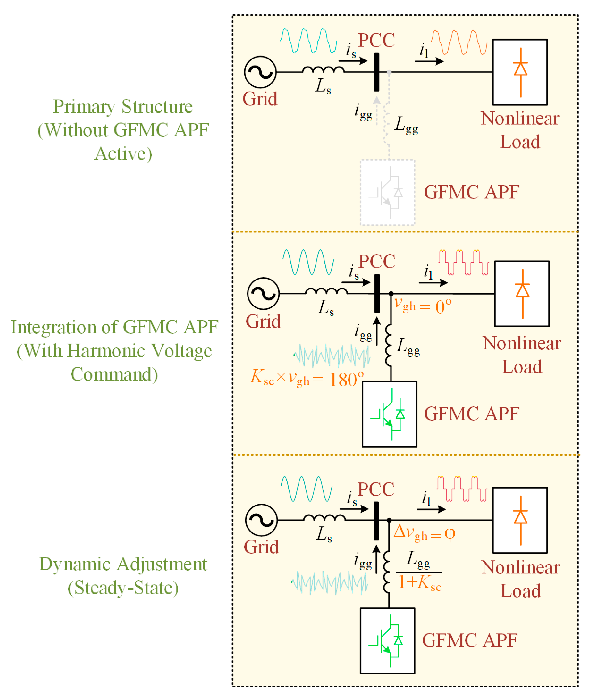
The harmonic compensation principle is illustrated in Figure 7, demonstrating the operation of the GFMC APF at the PCC when a nonlinear load is connected to the system. When the GFMC APF is inactive in the initial stage, the nonlinear load generates harmonic currents i1, which flow through the grid inductor Ls. These harmonic currents lead to significant harmonic voltage distortions at the PCC, as the grid inductor creates a reactive impedance that amplifies the effect of the harmonics. At this point, the harmonic distortions remain unmitigated because the GFMC APF is not active to counterbalance the effects of the nonlinear load, resulting in poor voltage quality at the PCC.
When the GFMC APF is activated, harmonic voltages at the PCC begin to be injected to counteract the harmonic distortions caused by the harmonic currents generated by the nonlinear load. During the transient stage, the harmonic voltage at the PCC is represented as vgh ∠0°, corresponding to the phase and magnitude of the harmonic disturbances present in the system. To mitigate these distortions effectively, the GFMC APF generates a harmonic voltage command with a phase opposite to the harmonic voltage, specifically Ksc × vgh ∠180°, where Ksc is the scaling factor determining the amplitude of the injected compensation voltage.
The tuning of Ksc is crucial for practical implementation. It is determined through a stability analysis, as outlined in Section 4, where the parameter is adjusted to optimize harmonic suppression while ensuring system stability. In practical systems, Ksc is constrained by the need to avoid excessive compensation that could lead to instability due to interactions with grid impedance; typically, it is limited to a range where the gain margin remains positive, with an upper bound set to prevent oscillations, as validated by simulations showing stable operation with Ksc values up to 0.3. The optimal Ksc value of 0.1, as selected in this study (refer to Table 2), balances these factors, ensuring effective harmonic mitigation without compromising grid stability. This harmonic voltage injection cancels the existing harmonic voltage by creating a constructive destructive interference effect.
This injection reduces the effective line impedance from Lgg to a lower value of Lgg/(1 + Ksc), effectively creating a low-impedance path for the harmonic currents. This low-impedance path enables the harmonic currents to flow through the GFMC APF rather than through the grid, greatly reducing the harmonic distortions at the PCC. As a result, the GFMC APF successfully suppresses the harmonic distortions, while the fundamental component of the voltage remains unaffected, preserving the stability of the grid’s operation.
In the steady-state operation, once the system has fully compensated for the harmonic distortions, the harmonic voltage at the PCC stabilizes to a new value of Δvghφ, where Δvgh represents the compensated harmonic voltage and φ is the phase angle shift caused by the compensation process. This steady-state compensation ensures that the grid voltage at the PCC is free from significant harmonic distortions, as the GFMC APF continues to provide dynamic compensation in response to any changes in the nonlinear load. By maintaining this harmonic compensation, the GFMC APF ensures that the voltage quality at the PCC remains high, facilitating stable grid operation and improving the overall power quality for systems operating under nonlinear load conditions.

6. Simulation Results

Simulations performed in MATLAB/Simulink (R2024a) assessed the proposed GFMC APF’s capabilities in harmonic suppression, power regulation, and improving the harmonic spectra of PCC voltages and grid-injected currents. Figure 8, Figure 9, Figure 10, Figure 11, Figure 12, Figure 13, Figure 14, Figure 15 and Figure 16 show that the system effectively maintains sinusoidal waveforms, significantly reduces voltage and current harmonics, and ensures stable real and reactive power dynamics.
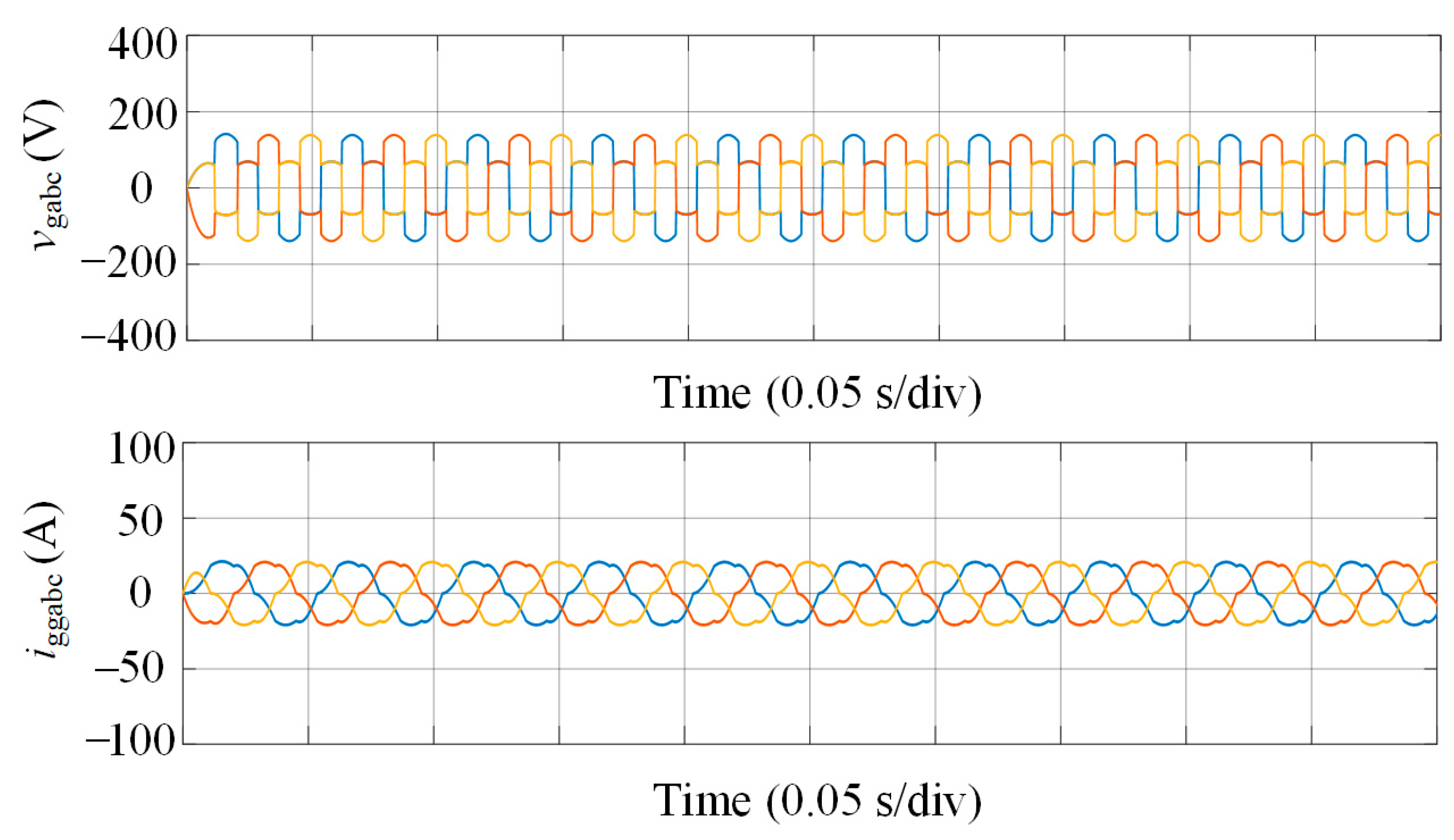
Figure 8 illustrates the system response without the GFMC APF, revealing significant power quality degradation. The vgabc shows noticeable distortion, with sharp peaks and notches, due to harmonic currents from the nonlinear load interacting with the grid impedance. Similarly, the iggabc are heavily distorted, exhibiting abrupt spikes from dominant 3rd, 5th, and 7th order harmonics, risking grid stability, with the simulation conducted at a nominal grid voltage of 110 Vrms and a 50 Hz frequency.
Figure 8. PCC voltages and grid-injected currents without GFMC APF.
Applsci 15 05927 g008
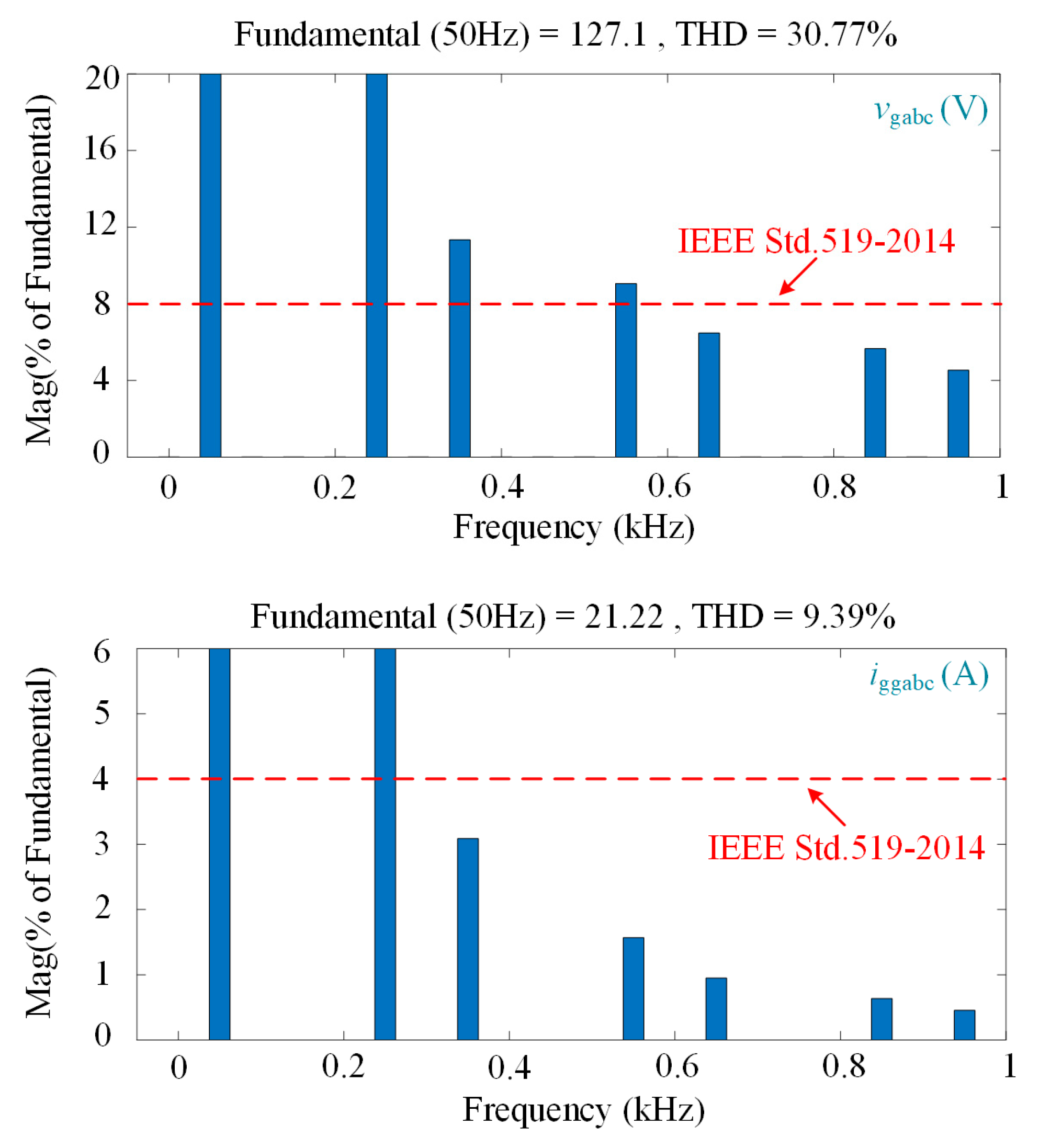
Figure 9 depicts the harmonic spectra of the system without the GFMC APF active, providing a baseline for the unmitigated harmonic distortion. The top graph shows the harmonic spectrum of vgabc, revealing a high THD of 30.77%, far exceeding the IEEE Std. 519-2014 limit of 8%, indicating severe voltage distortion caused by the nonlinear load. The bottom graph presents the harmonic spectrum of iggabc, displaying a high THD of 9.39%, surpassing the IEEE limit of 4%, with notable harmonic peaks at the same frequencies, underscoring the extent of current distortion in the absence of compensation. The simulation was run with a sampling and switching frequency of 10 kHz, as listed in Table 1.
Figure 9. Harmonic spectra of PCC voltages and grid currents without GFMC APF.
Applsci 15 05927 g009
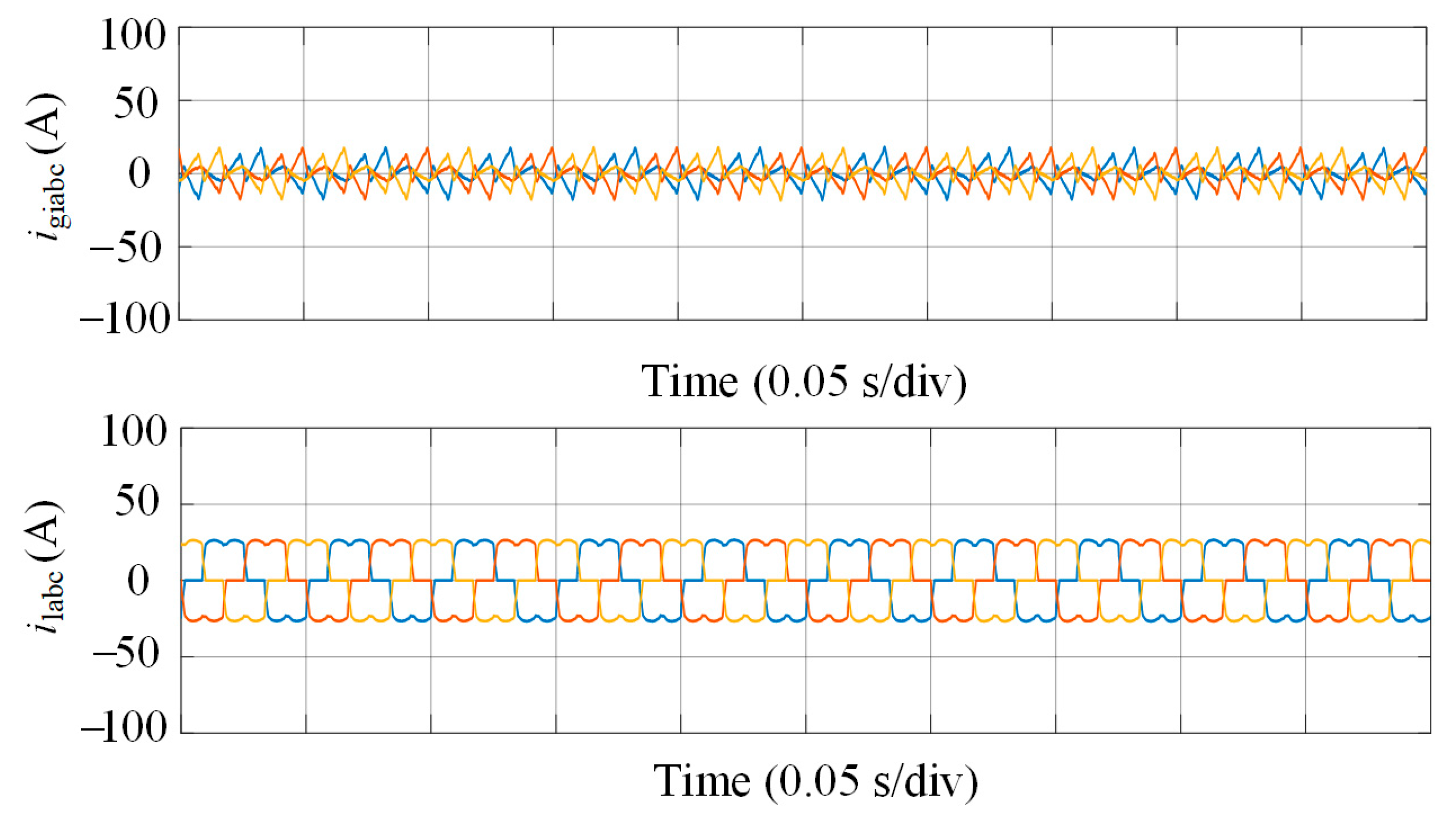
Figure 10 shows the performance of the GFMC APF under harmonic compensation, demonstrating its ability to mitigate distortions. The top graph displays the igiabc injected by the GFMC APF, which are specifically shaped to include harmonic components that are out of phase with those produced by the nonlinear load, effectively canceling them at the PCC. The bottom graph depicts the distorted load currents ilabc, characterized by sharp, non-sinusoidal peaks due to the diode bridge’s nonlinear behavior, highlighting the source of harmonic distortion that the GFMC APF targets.
Figure 10. Converter-side and nonlinear load currents under harmonic compensation operation.
Applsci 15 05927 g010
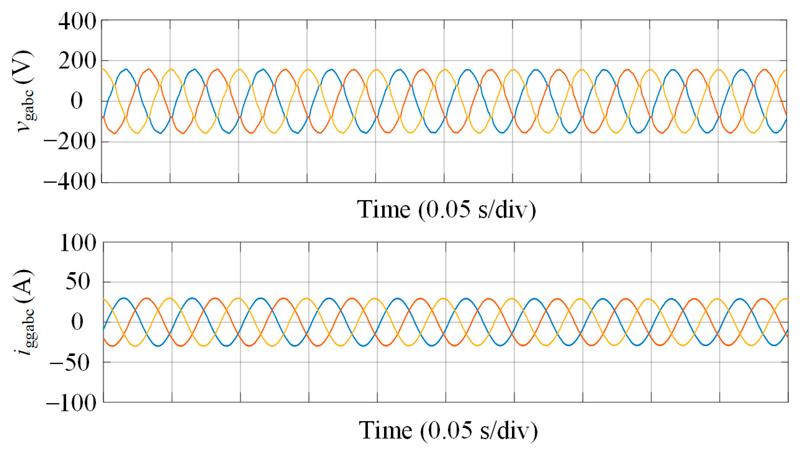
Figure 11 demonstrates the performance of the GFMC APF during operation, showcasing its effectiveness in maintaining power quality. The vgabc waveforms are perfectly sinusoidal, balanced, and stable, reflecting the GFMC APF capability to suppress harmonics and provide precise voltage regulation at the PCC, even under the influence of nonlinear loads. Additionally, the iggabc currents are clean and free of harmonic distortion, indicating that the GFMC APF compensating currents effectively neutralize the harmonics from the nonlinear load, ensuring seamless grid integration and maintaining system stability under challenging conditions. The controller settings were tuned to achieve a phase margin of 19.51 dB, as detailed in Section 4.2, with the repetitive controller (RC) gain adjusted to balance harmonic suppression and stability.
Figure 11. PCC voltages and grid-injected currents during GFMC APF operation.
Applsci 15 05927 g011
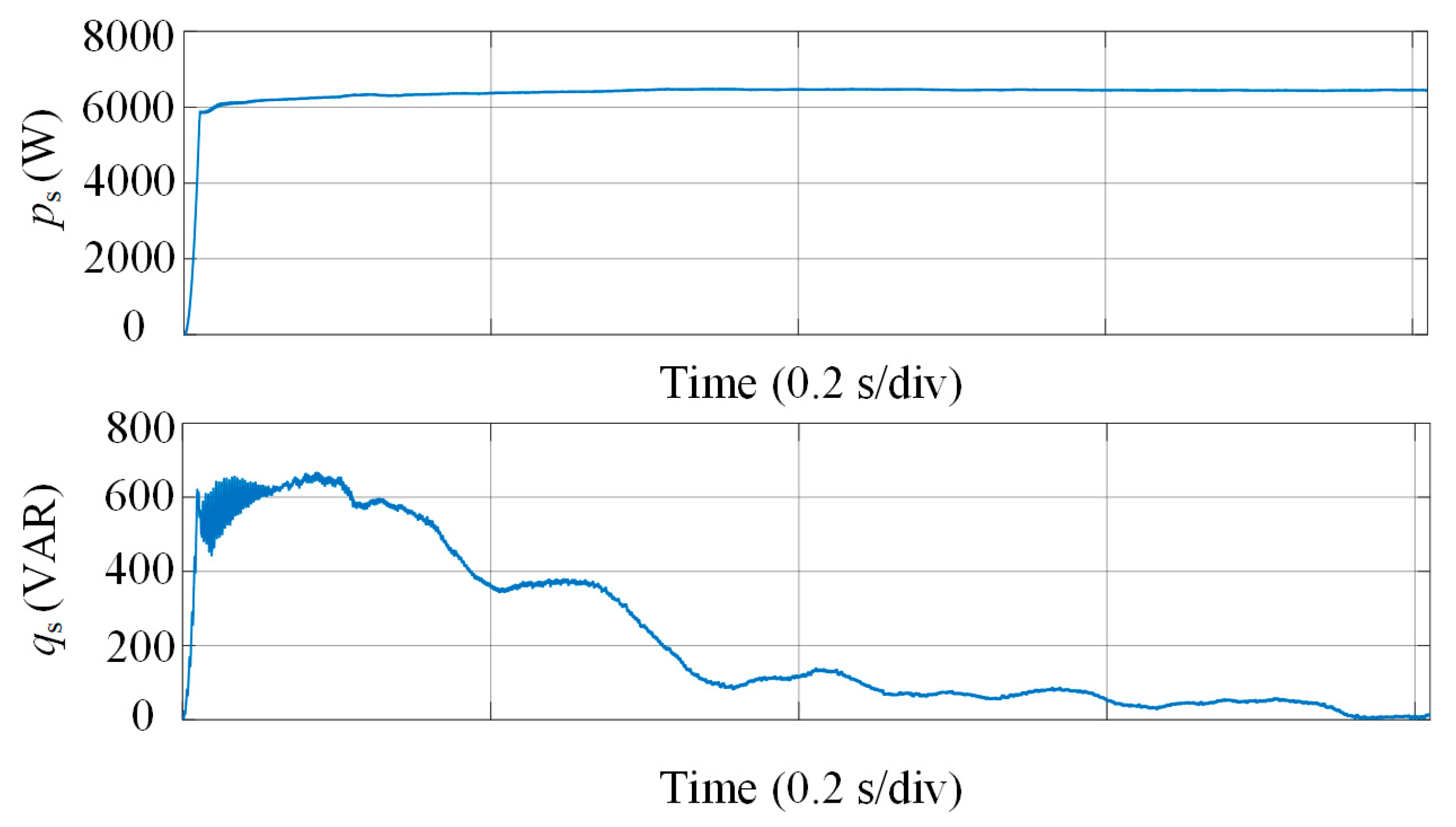
Figure 12 presents the system’s dynamic performance with the GFMC APF active, focusing on power regulation. The active power stabilizes at approximately 6000 W, demonstrating the GFMC APF’s capability for rapid and precise active power regulation, even with nonlinear loads that typically introduce disturbances. Meanwhile, the reactive power decreases steadily from around 600 VAR to near zero, highlighting the GFMC APF’s effectiveness in reactive power compensation, which reduces the burden on the grid, enhancing overall system efficiency and stability.
Figure 12. Active and reactive power dynamics during GFMC APF operation.
Applsci 15 05927 g012
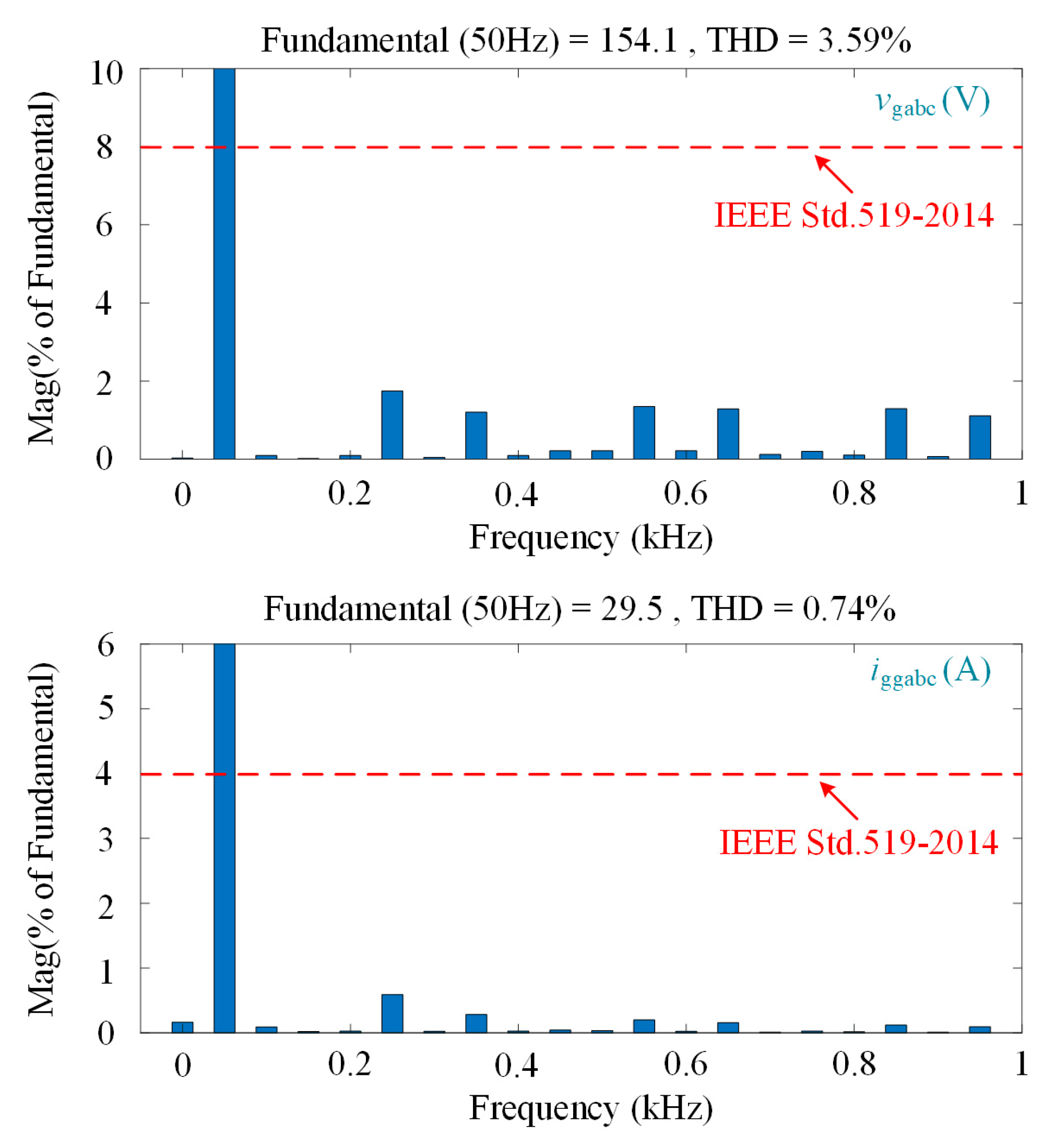
Figure 13 depicts the harmonic spectra of vgabc and iggabc, confirming the system’s compliance with IEEE Std. 519-2014. The PCC voltage exhibits a THD of 3.59%, remaining well within the allowable 8% limit, while the grid-injected current achieves an exceptionally low THD of 0.74%, far below the 4% threshold. These results highlight the effectiveness of the GFMC APF in harmonic suppression, ensuring high power quality by significantly reducing harmonic distortions compared to the unmitigated case shown in Figure 9.
Figure 13. Harmonic spectra of PCC voltages and grid currents under GFMC APF.
Applsci 15 05927 g013
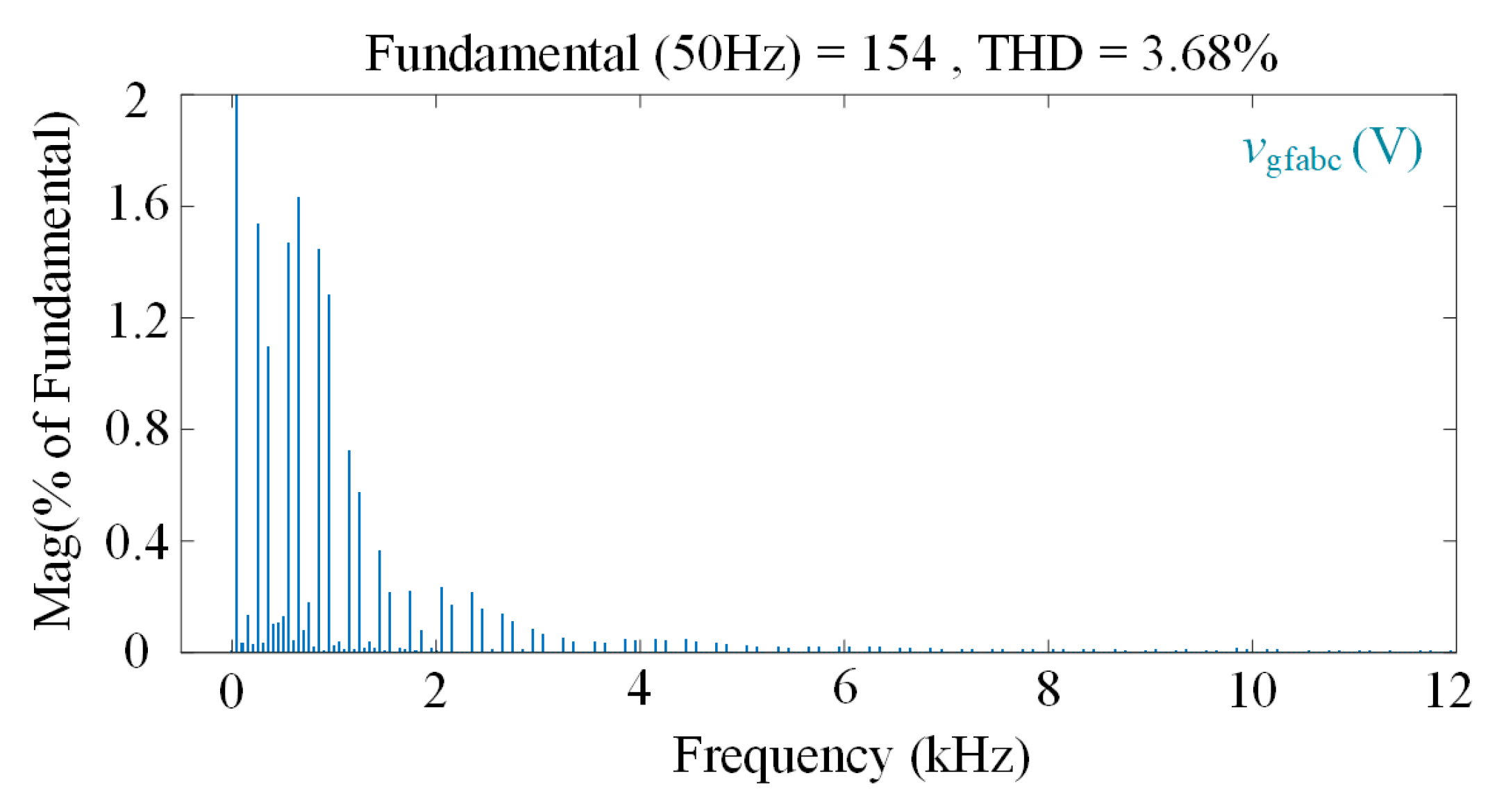
Figure 14 illustrates the harmonic spectra of the capacitor voltage vgfabc in the GFMC APF during operation, emphasizing supraharmonic content. The graph shows the magnitude of the fundamental and harmonic components as a percentage of the fundamental voltage, extending up to 12 kHz. The THD is 3.68%, reflecting effective harmonic suppression. Focusing on supraharmonics, the spectrum reveals that harmonic magnitudes decrease sharply beyond 1 kHz, with minimal components between 2 kHz and 12 kHz. This indicates that the GFMC APF successfully limits supraharmonic emissions in this frequency range, maintaining low amplitudes relative to the fundamental.
Figure 14. Harmonic spectra of capacitor voltages under GFMC APF.
Applsci 15 05927 g014
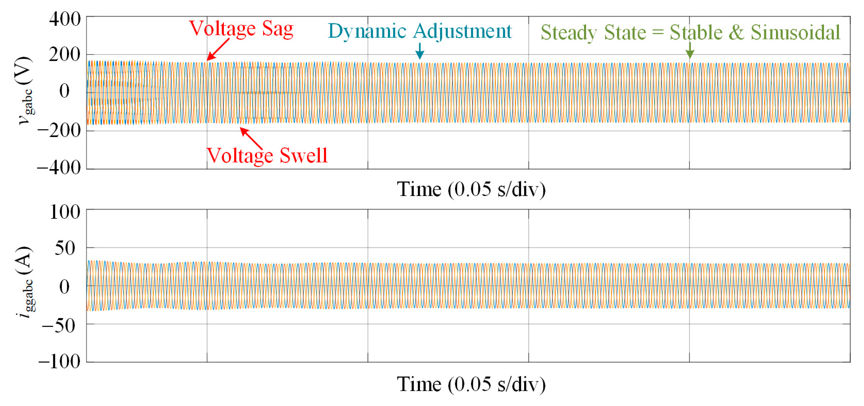
Figure 15 illustrates the response of the GFMC APF to non-stationary harmonic disturbances induced by variations in nonlinear load parameters. The top graph shows vgabc, which undergoes a voltage sag followed by a voltage swell. Despite these transient variations, the waveform remains sinusoidal, demonstrating the GFMC APF’s capability to maintain voltage quality under time-varying operating conditions. The bottom graph presents iggabc under the same scenario, which also remains stable and sinusoidal. These results demonstrate the effectiveness of the GFMC APF in suppressing harmonic distortion and maintaining high power quality in the presence of dynamic load changes.
Figure 15. PCC voltages and grid-injected currents under non-stationary harmonic conditions.
Applsci 15 05927 g015
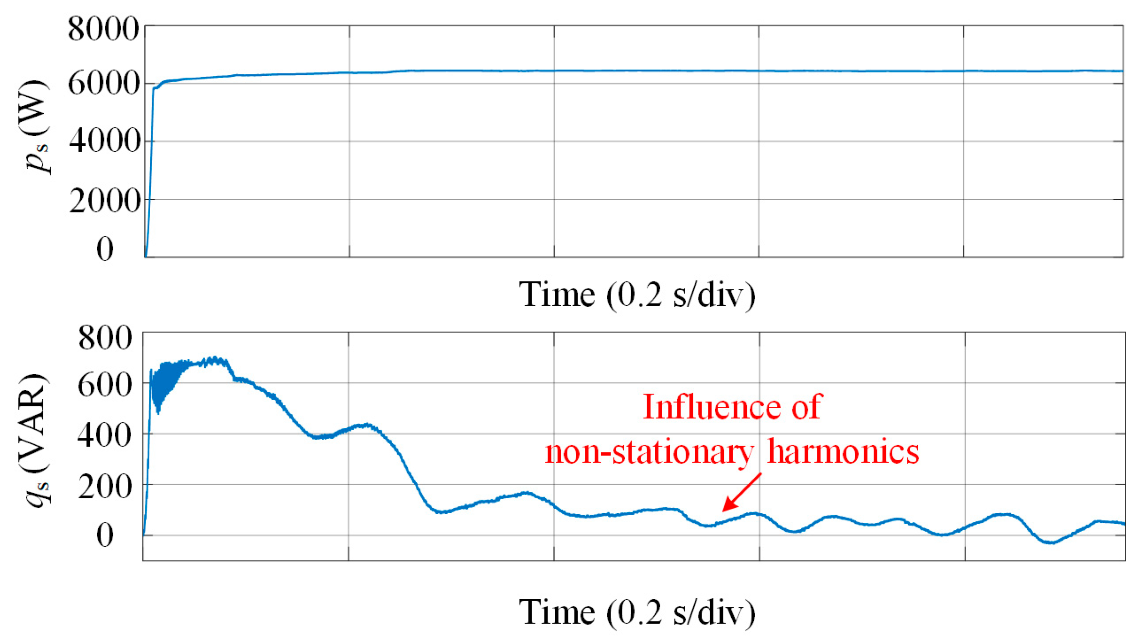
Figure 16 illustrates the active and reactive power dynamics of the GFMC APF under non-stationary harmonic conditions. The top graph displays the active power, which settles at approximately 6000 W after an initial transient, indicating effective power regulation in the presence of harmonic disturbances. The bottom graph shows the reactive power, which decreases from around 600 VAR to nearly zero, with transient fluctuations reflecting the impact of time-varying harmonic content. These results demonstrate the GFMC APF’s capability to regulate power flow and contribute to system-level stability under dynamic operating conditions.
Figure 16. Active and reactive power dynamics under non-stationary harmonic conditions.
Applsci 15 05927 g016

7. Conclusions

This article proposes a novel GFMC APF to address harmonic distortions in modern power grids with high renewable energy integration and nonlinear loads. By synergizing grid-forming converters’ voltage/frequency regulation capabilities with advanced harmonic suppression, the GFMC APF overcomes the limitations of conventional solutions like passive filters and grid-following APFs. The system employs a three-tier control architecture: (1) a power control module using droop strategies for grid synchronization and power regulation, (2) a voltage/current regulation module combining a repetitive controller (RC) and PI controller to suppress periodic harmonics while ensuring steady-state stability, and (3) a harmonic instruction generation module that extracts harmonic components from the PCC via dq-frame transformation and filtering for precise compensation. Stability analysis, validated through impedance modeling and Bode plots, demonstrates that the RC effectively mitigates harmonics at integer multiples of the fundamental frequency, with optimal tuning (e.g., Qz < 1) balancing suppression and stability. Simulations confirm the GFMC APF’s efficacy, reducing the PCC voltage THD to 3.59% and grid-injected current THD to 0.74%, compliant with IEEE Std. 519-2014. The system also enhances grid inertia, damping, and short-circuit capacity, ensuring sinusoidal waveforms and stable power dynamics under nonlinear loads. This integrated approach offers a scalable, cost-effective solution for improving power quality and stability in weak grids with high renewable penetration.

Author Contributions

Conceptualization, J.L.; methodology, J.L. and M.W.Q.; software, M.W.Q.; validation, M.W.Q., J.L., and J.F.; formal analysis, M.W.Q.; investigation, M.W.Q.; resources, J.L.; data curation, M.W.Q. and J.L.; writing—original draft preparation, M.W.Q.; writing—review and editing, M.W.Q. and J.F.; visualization, M.W.Q.; supervision, J.F.; project administration, J.F.; funding acquisition, J.F. All authors have read and agreed to the published version of the manuscript.

Funding

This work was supported in part by the Guangdong Basic and Applied Basic Research Foundation under Grant Guangdong-Shenzhen Joint Youth Fund, Grant Number 2022A1515110422, in part by the National Natural Science Foundation of China, Grant Number 20221017-9, Grant Number 52377192, Grant Number 12411530110, and in part by the Department of Science and Technology of Shandong Province under Grant Shandong Province Youth Fund under ZR202210270088.

Institutional Review Board Statement

Not applicable.

Informed Consent Statement

Not applicable.

Data Availability Statement

The original contributions presented in the study are included in the article, further inquiries can be directed to the corresponding author.

Conflicts of Interest

The authors declare no conflict of interest.

References

  1. Chakraborty, A. Advancements in power electronics and drives in interface with growing renewable energy resources. Renew. Sustain. Energy Rev. 2011, 15, 1816–1827. [Google Scholar] [CrossRef]
  2. Al-Shetwi, A.Q. Sustainable development of renewable energy integrated power sector: Trends, environmental impacts, and recent challenges. Sci. Total Environ. 2022, 822, 153645. [Google Scholar] [CrossRef] [PubMed]
  3. Akuzawa, Y.; Tsuji, K.; Matsumori, H.; Ito, Y.; Ezoe, T.; Sakai, K. A 95% efficient inverter with 300-W power output for 6.78-MHz magnetic resonant wireless power transfer system. In Proceedings of the IEEE/MTT-S International Microwave Symposium (IMS), Phoenix, AZ, USA, 17–22 May 2015. [Google Scholar]
  4. Meegahapola, L.; Sguarezi, A.; Bryant, J.S.; Gu, M.; Conde D, E.R.; Cunha, R.B.A. Power system stability with power-electronic converter interfaced renewable power generation: Present issues and future trends. Energies 2020, 13, 3441. [Google Scholar] [CrossRef]
  5. Michalec, Ł.; Jasiński, M.; Sikorski, T.; Leonowicz, Z.; Jasiński, Ł.; Suresh, V. Impact of harmonic currents of nonlinear loads on power quality of a low voltage network–review and case study. Energies 2021, 14, 3665. [Google Scholar] [CrossRef]
  6. Hu, Z.; Han, Y.; Zalhaf, A.S.; Zhou, S.; Zhao, E.; Yang, P. Harmonic sources modeling and characterization in modern power systems: A comprehensive overview. Electr. Power Syst. Res. 2023, 218, 109234. [Google Scholar] [CrossRef]
  7. Subjak, J.S.; Mcquilkin, J.S. Harmonies—Causes, effects, measurements, and analysis: An update. IEEE Trans. Ind. Appl. 1990, 26, 1034–1042. [Google Scholar] [CrossRef]
  8. Shazon, M.N.H.; Nahid-Al-Masood; Jawad, A. Frequency control challenges and potential countermeasures in future low-inertia power systems: A review. Energy Rep. 2022, 8, 6191–6219. [Google Scholar] [CrossRef]
  9. Nahid-Al-Masood; Modi, N.; Yan, R. Low inertia power systems: Frequency response challenges and a possible solution. In Proceedings of the Australasian Universities Power Engineering Conference (AUPEC), Brisbane, Australia, 25–28 September 2016; pp. 1–6. [Google Scholar]
  10. Abdollahi, R.; Gharehpetian, G.B.; Mohammadi, F.; Prakash P, S. Multi-pulse rectifier based on an optimal pulse doubling technique. Energies 2022, 15, 5567. [Google Scholar] [CrossRef]
  11. Badoni, M.; Singh, A.; Pandey, S.; Singh, B. Fractional-order notch filter for grid-connected solar pv system with power quality improvement. IEEE Trans. Ind. Electron. 2022, 69, 429–439. [Google Scholar] [CrossRef]
  12. Reguieg, Z.; Bouyakoub, I.; Mehedi, F. Harmonic mitigation in grid-integrated renewable energy systems with nonlinear loads. Energy 2025, 324, 135882. [Google Scholar] [CrossRef]
  13. Qaisar, M.W.; Fang, J.; Li, W. Switching harmonic attenuation of grid-tied converters using LLCL filters and MPC-SVPWM. In Proceedings of the 2024 IEEE 7th International Electrical and Energy Conference (CIEEC), Harbin, China, 10–12 May 2024; pp. 1566–1572. [Google Scholar]
  14. Fang, J.; Li, X.; Yang, X.; Tang, Y. An integrated trap-LCL filter with reduced current harmonics for grid-connected converters under weak grid conditions. IEEE Trans. Power Electron. 2017, 32, 8446–8457. [Google Scholar] [CrossRef]
  15. Zhang, H.; Liu, R.; Xue, C.; Li, Y. Active power enhancement control strategy of grid-forming inverters under asymmetrical grid faults. IEEE Trans. Power Electron. 2024, 39, 1447–1459. [Google Scholar] [CrossRef]
  16. Al-Shetwi, A.Q.; Issa, W.K.; Aqeil, R.F.; Ustun, T.S.; Al-Masri, H.M.; Alzaareer, K.; Abdolrasol, M.G.; Abdullah, M.A. Active power control to mitigate frequency deviations in large-scale grid-connected pv system using grid-forming single-stage inverters. Energies 2022, 15, 2035. [Google Scholar] [CrossRef]
  17. Howlader, A.M.; Sadoyama, S.; Roose, L.R.; Chen, Y. Active power control to mitigate voltage and frequency deviations for the smart grid using smart PV inverters. Appl. Energy 2020, 258, 114000. [Google Scholar] [CrossRef]
  18. Alam, M.S.; Al-Ismail, F.S.; Salem, A.; Abido, M.A. High-level penetration of renewable energy sources into grid utility: Challenges and solutions. IEEE Access 2020, 8, 190277–190299. [Google Scholar] [CrossRef]
  19. Rosso, R.; Wang, X.; Liserre, M.; Lu, X.; Engelken, S. Grid-forming converters: Control approaches, grid-synchronization, and future trends—A review. IEEE Open J. Ind. Appl. 2021, 2, 93–109. [Google Scholar] [CrossRef]
  20. Su, E.; Fang, J.; Fu, C.; Gao, F. DC grid-forming/following power converters with capacitive/battery energy storage. In Proceedings of the 2024 IEEE 10th International Power Electronics and Motion Control Conference (IPEMC ECCE Asia), Wuhan, China, 19–22 May 2024; pp. 2511–2516. [Google Scholar]
  21. Rosso, R.; Engelken, S.; Liserre, M. Robust stability investigation of the interactions among grid-forming and grid-following converters. IEEE J. Emerg. Sel. Top. Power Electron. 2020, 8, 991–1003. [Google Scholar] [CrossRef]
  22. IEEE 519-2014; IEEE Recommended Practice and Requirements for Harmonic Control in Electric Power Systems. PE/T&D-Transmission and Distribution: Chicago, IL, USA, 2014.
  23. Van de Sype, D.M.; De Gusseme, K.; De Belie, F.M.L.L.; Van den Bossche, A.P.; Melkebeek, J.A. Small-signal z-domain analysis of digitally controlled converters. IEEE Trans. Power Electron. 2006, 21, 470–478. [Google Scholar] [CrossRef]
  24. Maeda, G.J.; Manchester, I.R.; Rye, D.C. Combined ILC and disturbance observer for the rejection of near-repetitive disturbances, with application to excavation. IEEE Trans. Control Syst. Technol. 2015, 23, 1754–1769. [Google Scholar] [CrossRef]
Figure 1. Future grids powered by RESs and electronics.
Applsci 15 05927 g001
Figure 2. Schematic diagram of GFMC APF.
Applsci 15 05927 g002
Figure 3. Control block diagram of GFMC APF.
Applsci 15 05927 g003
Figure 4. Simplified control block diagram of GFMC APF with system dynamics.
Applsci 15 05927 g004
Figure 5. Bode plots of the system without RC.
Applsci 15 05927 g005
Figure 6. Bode plots of the system with and without RC.
Applsci 15 05927 g006
Figure 7. Harmonic compensation principle of GFMC APF.
Applsci 15 05927 g007
Table 1. System parameters.
DescriptionSymbolValue
Nominal dc voltageVdc400 V
Grid voltageVs110 Vrms
Converter-side inductorLgi2 mH
Grid-side inductorLgg4 μH
Line inductorLs10 mH
Load inductorLload20 μH
Filter capacitanceCgf50 μF
Grid resistanceRs0.1 Ω
Load resistanceRload10 Ω
Nominal frequencyf050 Hz
Switching frequencyfsw10 kHz
Active power referencePg_ref0 W
Table 2. Control parameters.
DescriptionSymbolValue
Active power droop gainDp2.85 × 10−3
Reactive power droop gainDq14.2 × 10−3
Voltage controller P gainKvp0.14
Voltage controller I gainKvi60
Current controller P gainKcp0.1
RC scaling factorK6
RC gainKr0.22
RC filter coefficientQz0.99
Short-circuit coefficientKsc0.1
Table 3. Effects of Kr and Qz on system stability and harmonic suppression.
RC GainEffect with Qz = 1Effect with Qz < 1
Kr = 0.1Moderate harmonic suppression, high-frequency peaks presentSmooth high-frequency response, high gain margin, stable system
Kr = 0.3Effective harmonic suppression, prominent harmonic peaksReduced high-frequency instability, moderate gain margin, reduced stability
Kr = 0.5Strong harmonic suppression, very prominent harmonic peaksMitigated high-frequency peaks, low gain margins, unstable system
Disclaimer/Publisher’s Note: The statements, opinions and data contained in all publications are solely those of the individual author(s) and contributor(s) and not of MDPI and/or the editor(s). MDPI and/or the editor(s) disclaim responsibility for any injury to people or property resulting from any ideas, methods, instructions or products referred to in the content.

