1. Introduction
The increasing integration of renewable energy sources (RESs) and power electronics-based devices in modern power grids has significantly improved flexibility, efficiency, and environmental sustainability [
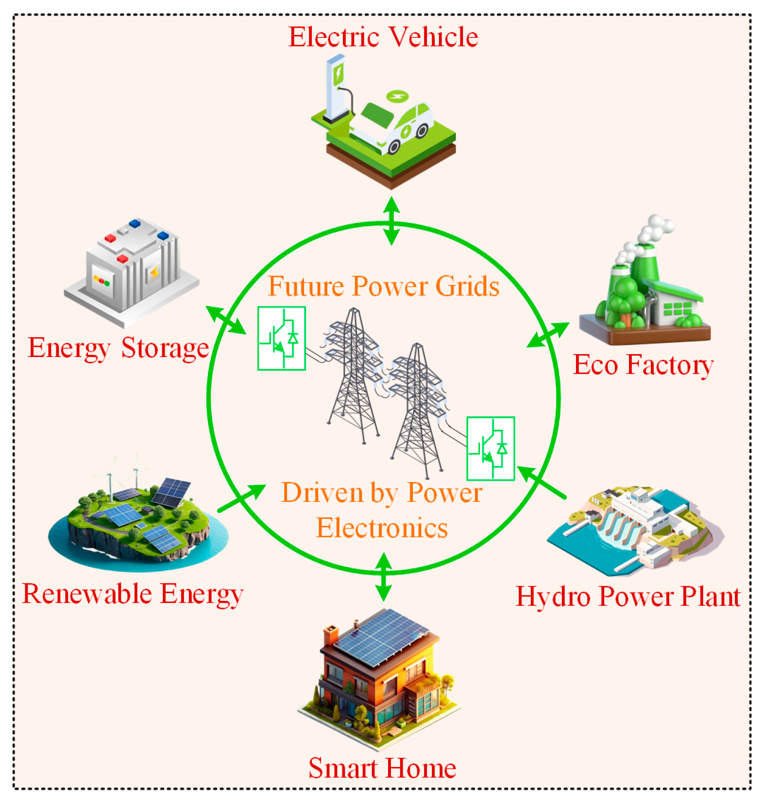
1], as shown in
Figure 1. The integration of RESs, such as solar and wind power, has enabled more decentralized and cleaner power generation, reducing dependence on fossil fuels and lowering carbon emissions [
2]. Additionally, power electronics-based devices, such as inverters and converters, have enhanced grid flexibility by enabling more precise control over power flow, with recent advancements achieving up to 95% efficiency in high-power inverters [
3]. However, this shift also introduces various technical challenges related to power quality and system stability [
4]. Nonlinear loads, such as variable speed drives, rectifiers, and other power electronic devices, generate harmonic currents that distort the voltage waveform, with total harmonic distortion (THD) levels reaching as high as 30% in systems with significant nonlinear load penetration [
5,
6]. This harmonic distortion can lead to various issues, including transformer overheating, higher system losses, and interference with sensitive electronic equipment [
7]. Furthermore, replacing traditional synchronous generators with RESs interfaced via voltage source converters has reduced system inertia, which plays a crucial role in damping frequency disturbances and ensuring stability in the grid [
4]. This reduction in inertia increases the grid’s sensitivity to frequency deviations, particularly under sudden load changes or renewable generation variability, as discussed [
8,
9].
In recent years, significant advancements have been made in addressing these challenges. For instance, using advanced power electronic converters in RES integration has improved power quality, with multi-pulse rectifiers reducing harmonic distortions to below 5% in grid-connected photovoltaic (PV) systems [
10]. Additionally, grid-connected PV systems employing Fractional Order Notch Filters (FNOFs) have demonstrated the ability to mitigate harmonic currents, achieving a THD reduction to 3.5% while compensating for reactive power and load unbalancing [
11]. Moreover, the application of Unified Power Quality Conditioners (UPQCs) in PV–wind systems has successfully reduced THD from over 55% to below 2.23%, ensuring stable voltage and current levels under various operating conditions [
12]. These advancements highlight the progress in managing power quality and stability issues in RES-dominated grids.
Conventional solutions, such as passive power filters, have been employed to mitigate harmonic distortions [
13]. Passive filters are designed to attenuate specific harmonic frequencies, but they are often bulky, inflexible, and prone to resonance, making them unsuitable for dynamic systems where the harmonic spectrum can vary with load conditions. These systems also lack adaptability and cannot adjust to changing grid conditions, leading to inefficient performance when harmonic spectra vary with load [
14]. On the other hand, active power filters (APFs) offer a more flexible, dynamic solution by compensating for harmonic currents in real time, achieving THD reductions to below 5% in grid-connected scenarios [
15]. APFs can operate in both grid-connected and islanded modes, allowing them to adapt to varying grid conditions and load changes while providing more precise harmonic mitigation [
16]. However, most APFs operate in grid-following mode, meaning they rely on an existing grid voltage for synchronization, making them dependent on grid stability and less effective in weak grids where voltage fluctuations exceed 10% [
17,
18]. While effective in mitigating harmonic currents, these systems cannot provide essential grid-supportive services, such as voltage regulation, frequency support, and enhanced damping, which are necessary in grids with high-RES penetration.
GFMCs have emerged as a promising solution to address the above-mentioned shortcomings. These converters enable direct control over grid voltage and frequency by emulating the dynamic behavior of conventional synchronous generators. This capability supports enhanced grid stability, particularly in low-inertia or weak grid environments. This capability allows them to provide essential grid-supportive services, such as voltage regulation and frequency control, even in islanded or weak grid conditions, as discussed in [
19]. Unlike grid-following systems, GFMCs do not require phase-locked loops for synchronization, which makes them capable of operating independently in islanded conditions or weak grids, offering a more robust solution for modern power systems [
20,
21]. Despite their advantages, GFMCs have primarily focused on voltage and frequency regulation, while harmonic mitigation has not been fully integrated into their control strategies. This gap presents a significant challenge for modern power systems, as harmonic distortions remain a critical issue, especially in grids with high RES and nonlinear load penetration.
This paper proposes a novel GFMC APF that integrates the voltage and frequency control capabilities of GFMCs with advanced harmonic filtering to address the limitations of conventional APFs. The GFMC APF utilizes harmonic extraction from the PCC to generate precise harmonic voltage components, which are then used to generate compensating currents that reduce harmonic distortion and minimize disruptions in the system. The innovative control method of the GFMC APF ensures fast frequency and voltage regulation while enhancing grid stability by improving inertia, damping, and short-circuit capacity. This makes the system particularly effective in low-inertia grids where maintaining stability is more challenging, ensuring that the grid can effectively support increasing RES penetration without compromising power quality. The major contributions of this work are as follows:
- (a)
Developing a GFMC APF control method that integrates grid-forming functionality with harmonic suppression to improve power quality in weak grids.
- (b)
Proposing a precise harmonic extraction technique using PCC voltage measurements for accurate mitigation without affecting fundamental operations.
- (c)
Designing a scalable and cost-effective control approach that eliminates complex parameter tuning, enabling seamless deployment in modern power systems.
The structure of this paper is as follows:
Section 2 presents the GFMC APF system configuration, detailing its integration into the grid and harmonic mitigation components.
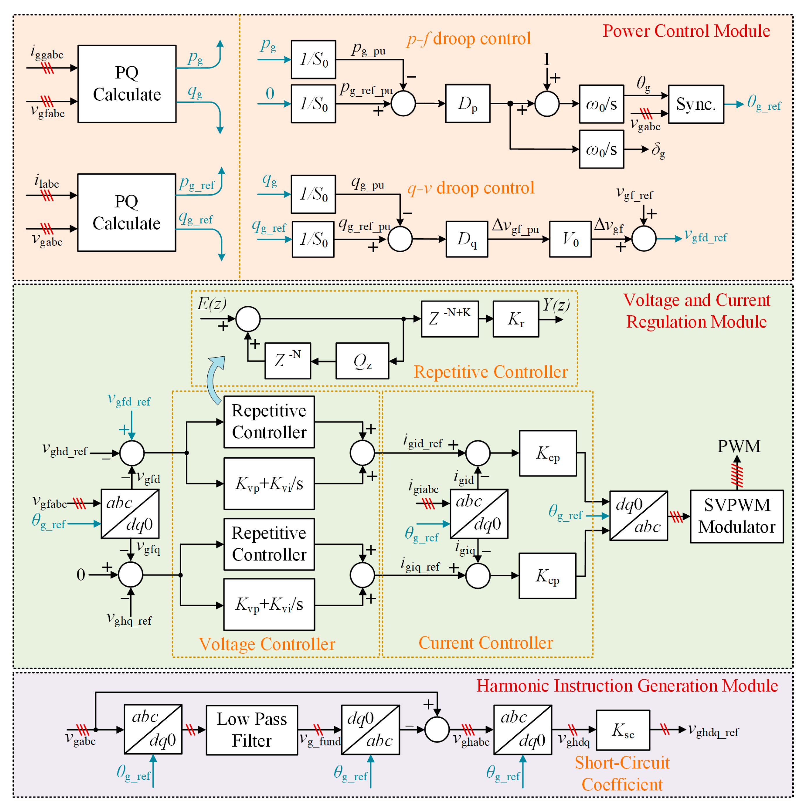
Section 3 describes the control structure, focusing on harmonic suppression and grid synchronization.
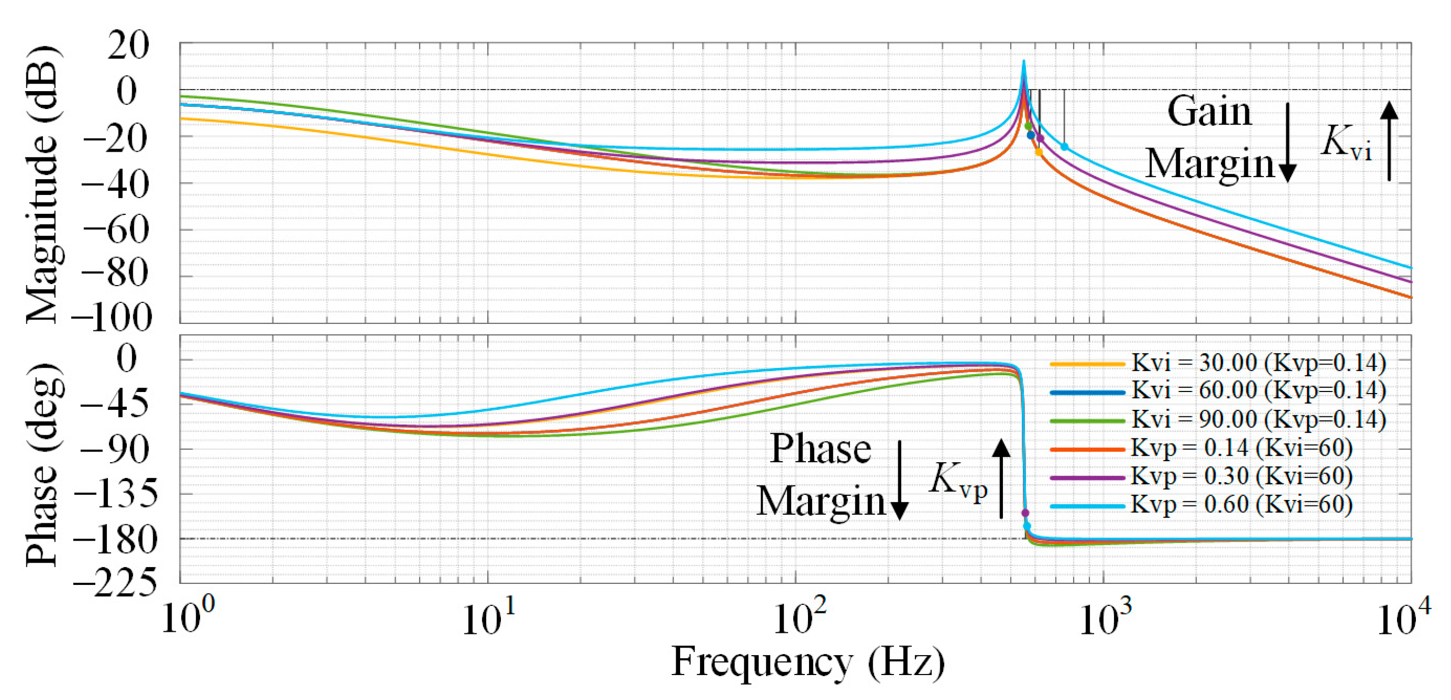
Section 4 examines the stability analysis, focusing on controller tuning and its impact on system stability.
Section 5 describes the harmonic compensation principle.
Section 6 presents simulation results to demonstrate the effectiveness of the proposed method. Finally,
Section 7 concludes the paper.
2. System Configuration
The schematic diagram in
Figure 2 illustrates the GFMC APF system. The system is powered by a DC link, represented by
vgdc, which could be a battery or another converter. The power electronics section consists of a GFMC controlled by pulse-width modulation (PWM) signals to generate the desired output. The interface between the converter and the grid is achieved through an
LCL filter, comprising the converter-side inductor
Lgi, the filter capacitor
Cgf, and the grid-side inductor
Lgg. The primary control objective is to regulate the capacitor voltages
vgfabc to control the phase and magnitude of power injected into the grid. The nonlinear load, connected at the PCC, generates the harmonic currents
ilabc, which the GFMC APF compensates for, ensuring harmonic-free grid-injected currents
iggabc. The nonlinear load is modeled with an inductor
Lload and a resistance
Rload, representing its dynamic characteristics, and is configured as a three-phase diode bridge. The grid is defined as a series connection of grid inductors
Ls and grid voltage sources
vsabc. Voltages at the PCC,
vgabc are measured for grid synchronization, and the injected power is regulated through the control of
vgfabc. This setup ensures effective power transfer, grid synchronization, and harmonic suppression.
5. Harmonic Compensation Principle
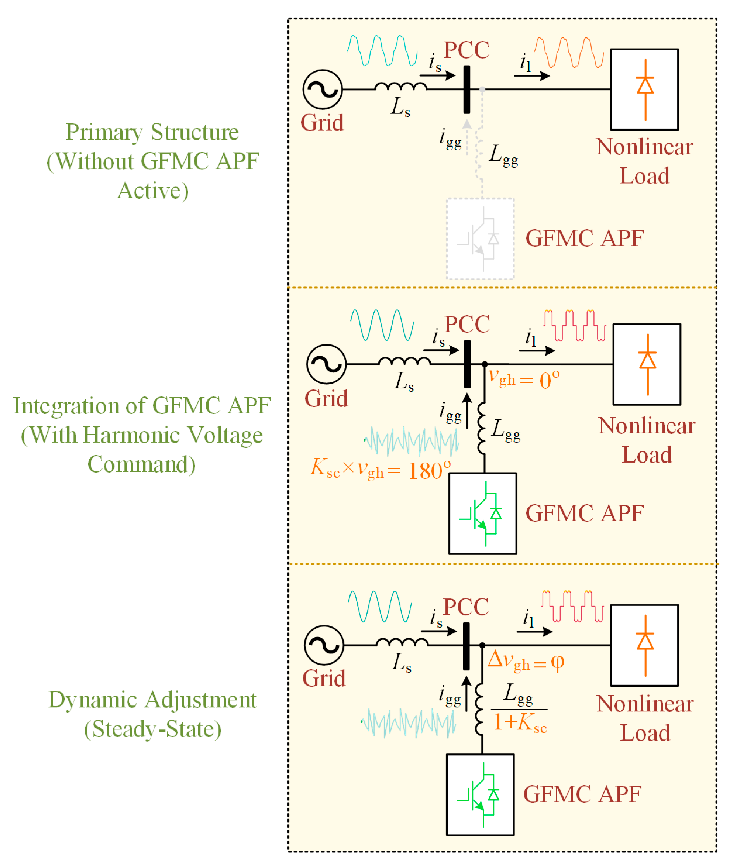
The harmonic compensation principle is illustrated in
Figure 7, demonstrating the operation of the GFMC APF at the PCC when a nonlinear load is connected to the system. When the GFMC APF is inactive in the initial stage, the nonlinear load generates harmonic currents
i1, which flow through the grid inductor
Ls. These harmonic currents lead to significant harmonic voltage distortions at the PCC, as the grid inductor creates a reactive impedance that amplifies the effect of the harmonics. At this point, the harmonic distortions remain unmitigated because the GFMC APF is not active to counterbalance the effects of the nonlinear load, resulting in poor voltage quality at the PCC.
When the GFMC APF is activated, harmonic voltages at the PCC begin to be injected to counteract the harmonic distortions caused by the harmonic currents generated by the nonlinear load. During the transient stage, the harmonic voltage at the PCC is represented as vgh ∠0°, corresponding to the phase and magnitude of the harmonic disturbances present in the system. To mitigate these distortions effectively, the GFMC APF generates a harmonic voltage command with a phase opposite to the harmonic voltage, specifically Ksc × vgh ∠180°, where Ksc is the scaling factor determining the amplitude of the injected compensation voltage.
The tuning of
Ksc is crucial for practical implementation. It is determined through a stability analysis, as outlined in
Section 4, where the parameter is adjusted to optimize harmonic suppression while ensuring system stability. In practical systems,
Ksc is constrained by the need to avoid excessive compensation that could lead to instability due to interactions with grid impedance; typically, it is limited to a range where the gain margin remains positive, with an upper bound set to prevent oscillations, as validated by simulations showing stable operation with
Ksc values up to 0.3. The optimal
Ksc value of 0.1, as selected in this study (refer to
Table 2), balances these factors, ensuring effective harmonic mitigation without compromising grid stability. This harmonic voltage injection cancels the existing harmonic voltage by creating a constructive destructive interference effect.
This injection reduces the effective line impedance from Lgg to a lower value of Lgg/(1 + Ksc), effectively creating a low-impedance path for the harmonic currents. This low-impedance path enables the harmonic currents to flow through the GFMC APF rather than through the grid, greatly reducing the harmonic distortions at the PCC. As a result, the GFMC APF successfully suppresses the harmonic distortions, while the fundamental component of the voltage remains unaffected, preserving the stability of the grid’s operation.
In the steady-state operation, once the system has fully compensated for the harmonic distortions, the harmonic voltage at the PCC stabilizes to a new value of Δvgh∠φ, where Δvgh represents the compensated harmonic voltage and φ is the phase angle shift caused by the compensation process. This steady-state compensation ensures that the grid voltage at the PCC is free from significant harmonic distortions, as the GFMC APF continues to provide dynamic compensation in response to any changes in the nonlinear load. By maintaining this harmonic compensation, the GFMC APF ensures that the voltage quality at the PCC remains high, facilitating stable grid operation and improving the overall power quality for systems operating under nonlinear load conditions.
6. Simulation Results
Simulations performed in MATLAB/Simulink (R2024a) assessed the proposed GFMC APF’s capabilities in harmonic suppression, power regulation, and improving the harmonic spectra of PCC voltages and grid-injected currents.
Figure 8,
Figure 9,
Figure 10,
Figure 11,
Figure 12,
Figure 13,
Figure 14,
Figure 15 and
Figure 16 show that the system effectively maintains sinusoidal waveforms, significantly reduces voltage and current harmonics, and ensures stable real and reactive power dynamics.
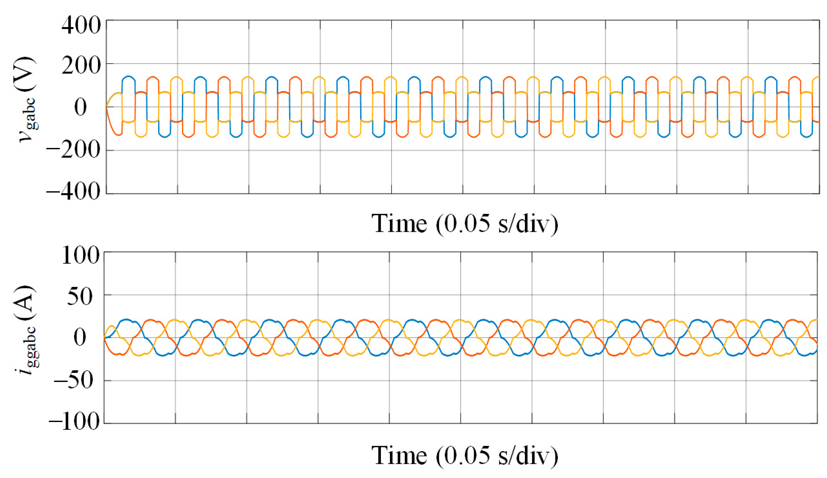
Figure 8 illustrates the system response without the GFMC APF, revealing significant power quality degradation. The
vgabc shows noticeable distortion, with sharp peaks and notches, due to harmonic currents from the nonlinear load interacting with the grid impedance. Similarly, the
iggabc are heavily distorted, exhibiting abrupt spikes from dominant 3rd, 5th, and 7th order harmonics, risking grid stability, with the simulation conducted at a nominal grid voltage of 110 Vrms and a 50 Hz frequency.
Figure 8.
PCC voltages and grid-injected currents without GFMC APF.
Figure 8.
PCC voltages and grid-injected currents without GFMC APF.
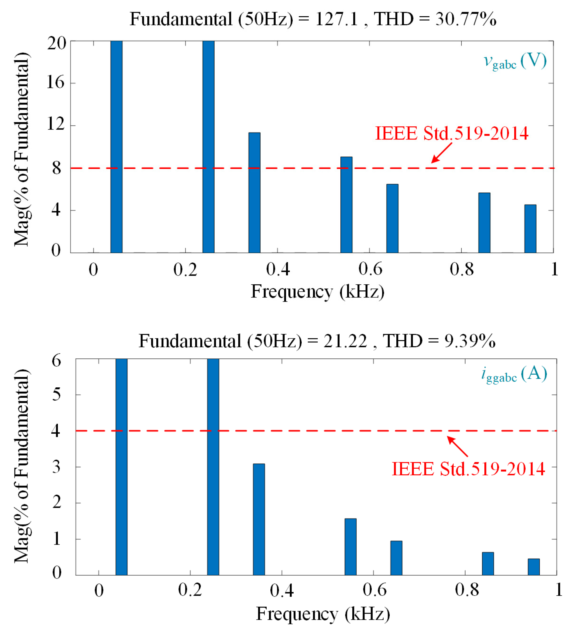
Figure 9 depicts the harmonic spectra of the system without the GFMC APF active, providing a baseline for the unmitigated harmonic distortion. The top graph shows the harmonic spectrum of
vgabc, revealing a high THD of 30.77%, far exceeding the IEEE Std. 519-2014 limit of 8%, indicating severe voltage distortion caused by the nonlinear load. The bottom graph presents the harmonic spectrum of
iggabc, displaying a high THD of 9.39%, surpassing the IEEE limit of 4%, with notable harmonic peaks at the same frequencies, underscoring the extent of current distortion in the absence of compensation. The simulation was run with a sampling and switching frequency of 10 kHz, as listed in
Table 1.
Figure 9.
Harmonic spectra of PCC voltages and grid currents without GFMC APF.
Figure 9.
Harmonic spectra of PCC voltages and grid currents without GFMC APF.
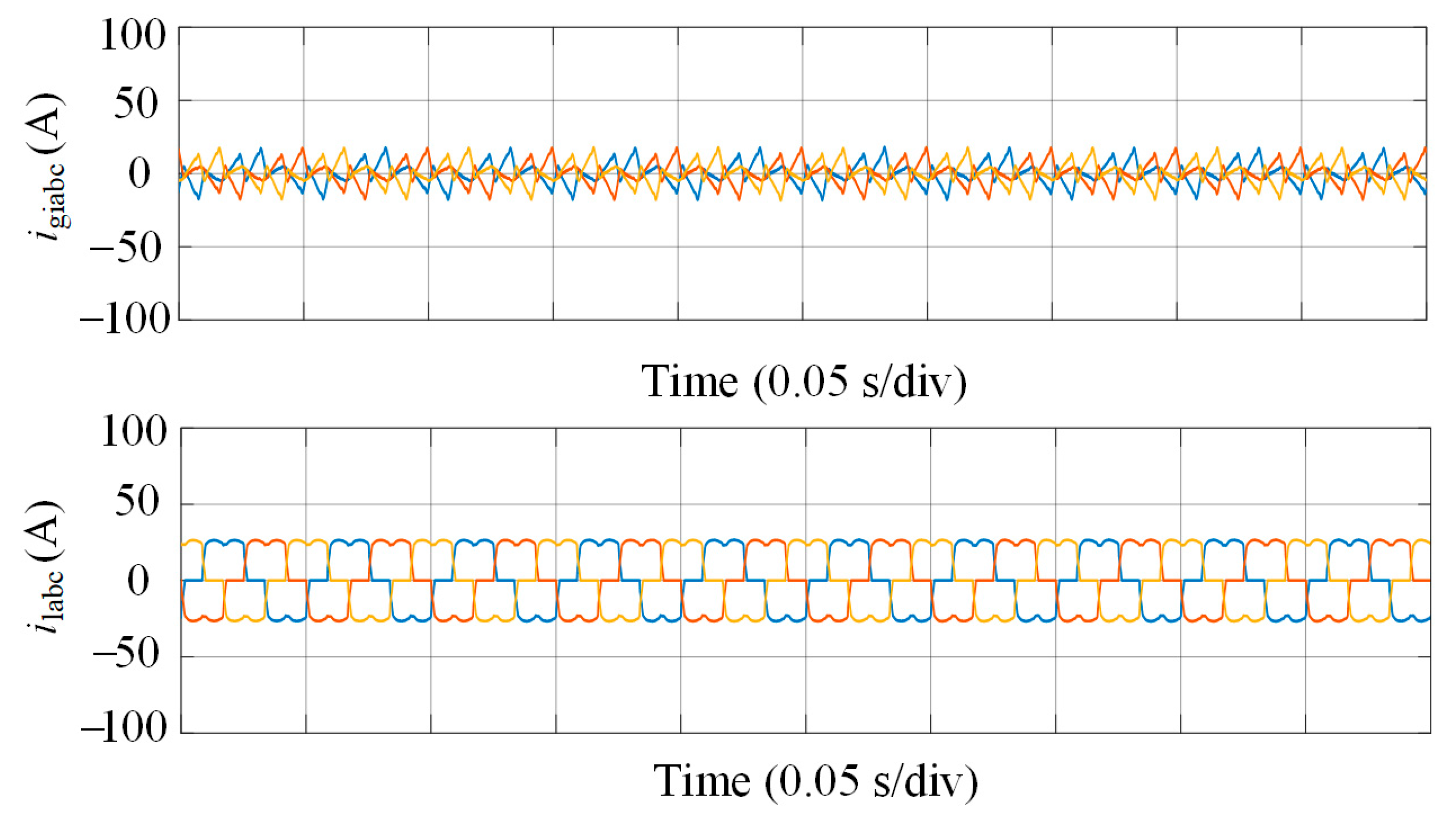
Figure 10 shows the performance of the GFMC APF under harmonic compensation, demonstrating its ability to mitigate distortions. The top graph displays the
igiabc injected by the GFMC APF, which are specifically shaped to include harmonic components that are out of phase with those produced by the nonlinear load, effectively canceling them at the PCC. The bottom graph depicts the distorted load currents
ilabc, characterized by sharp, non-sinusoidal peaks due to the diode bridge’s nonlinear behavior, highlighting the source of harmonic distortion that the GFMC APF targets.
Figure 10.
Converter-side and nonlinear load currents under harmonic compensation operation.
Figure 10.
Converter-side and nonlinear load currents under harmonic compensation operation.
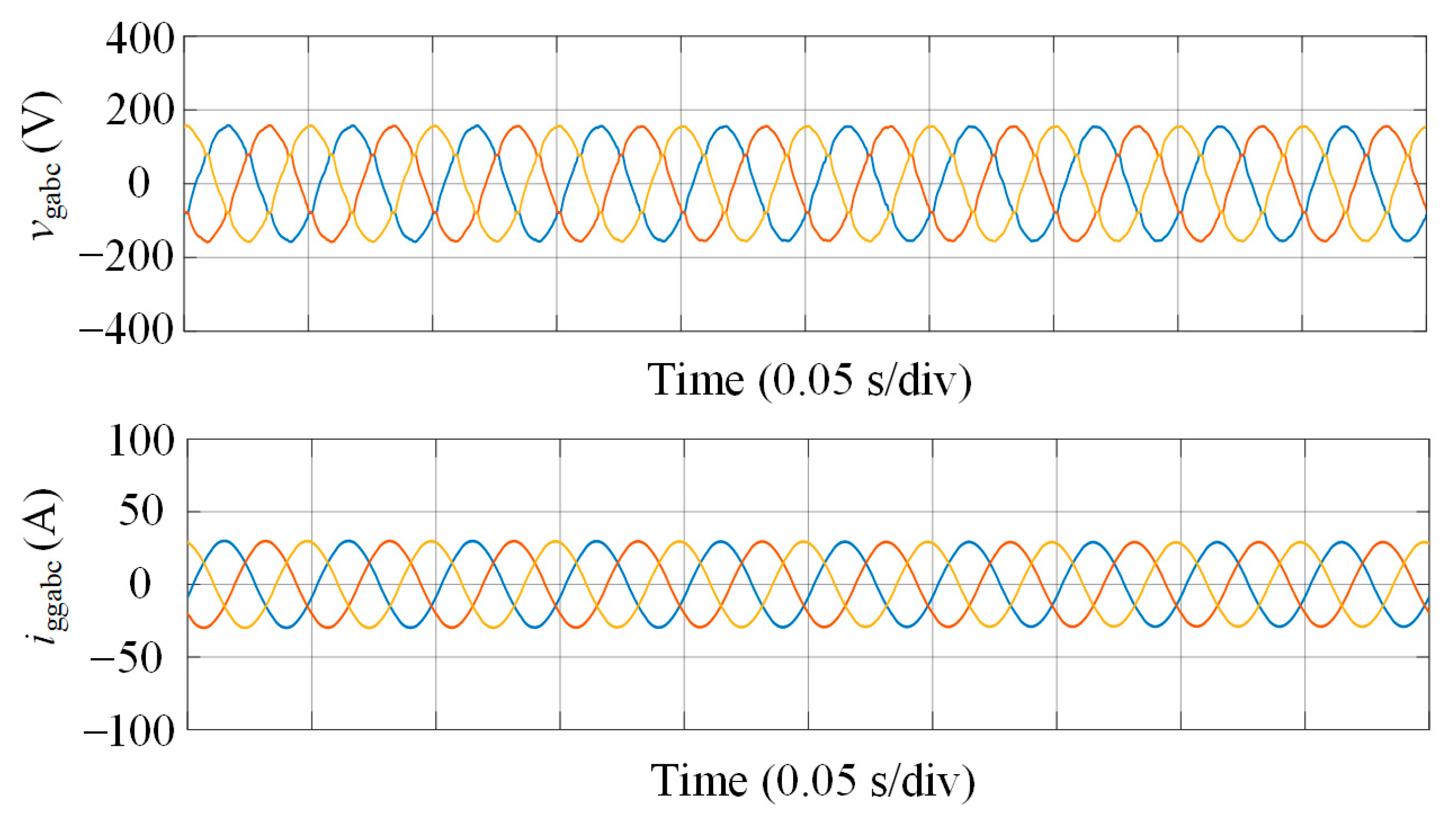
Figure 11 demonstrates the performance of the GFMC APF during operation, showcasing its effectiveness in maintaining power quality. The
vgabc waveforms are perfectly sinusoidal, balanced, and stable, reflecting the GFMC APF capability to suppress harmonics and provide precise voltage regulation at the PCC, even under the influence of nonlinear loads. Additionally, the
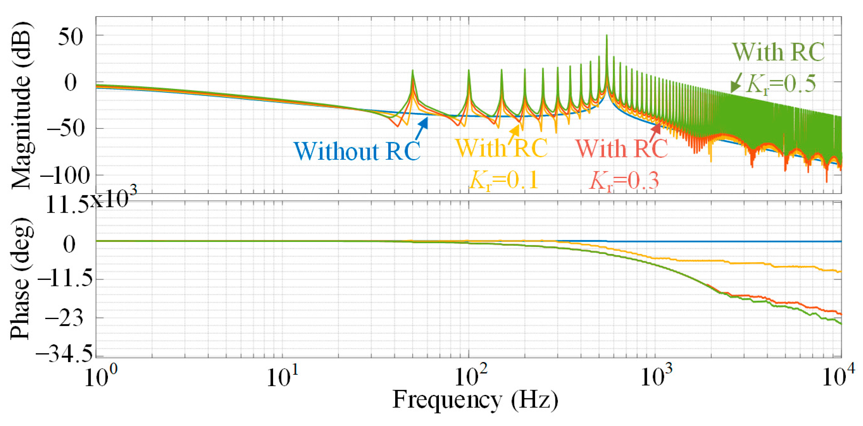
iggabc currents are clean and free of harmonic distortion, indicating that the GFMC APF compensating currents effectively neutralize the harmonics from the nonlinear load, ensuring seamless grid integration and maintaining system stability under challenging conditions. The controller settings were tuned to achieve a phase margin of 19.51 dB, as detailed in
Section 4.2, with the repetitive controller (RC) gain adjusted to balance harmonic suppression and stability.
Figure 11.
PCC voltages and grid-injected currents during GFMC APF operation.
Figure 11.
PCC voltages and grid-injected currents during GFMC APF operation.
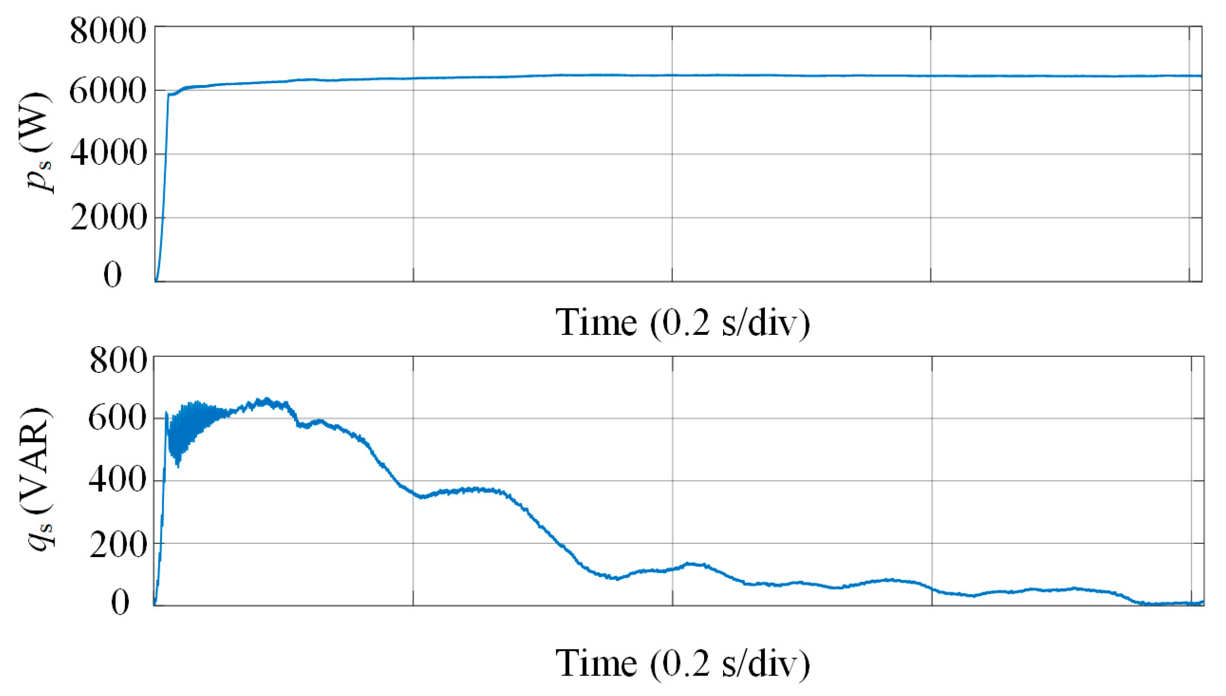
Figure 12 presents the system’s dynamic performance with the GFMC APF active, focusing on power regulation. The active power stabilizes at approximately 6000 W, demonstrating the GFMC APF’s capability for rapid and precise active power regulation, even with nonlinear loads that typically introduce disturbances. Meanwhile, the reactive power decreases steadily from around 600 VAR to near zero, highlighting the GFMC APF’s effectiveness in reactive power compensation, which reduces the burden on the grid, enhancing overall system efficiency and stability.
Figure 12.
Active and reactive power dynamics during GFMC APF operation.
Figure 12.
Active and reactive power dynamics during GFMC APF operation.
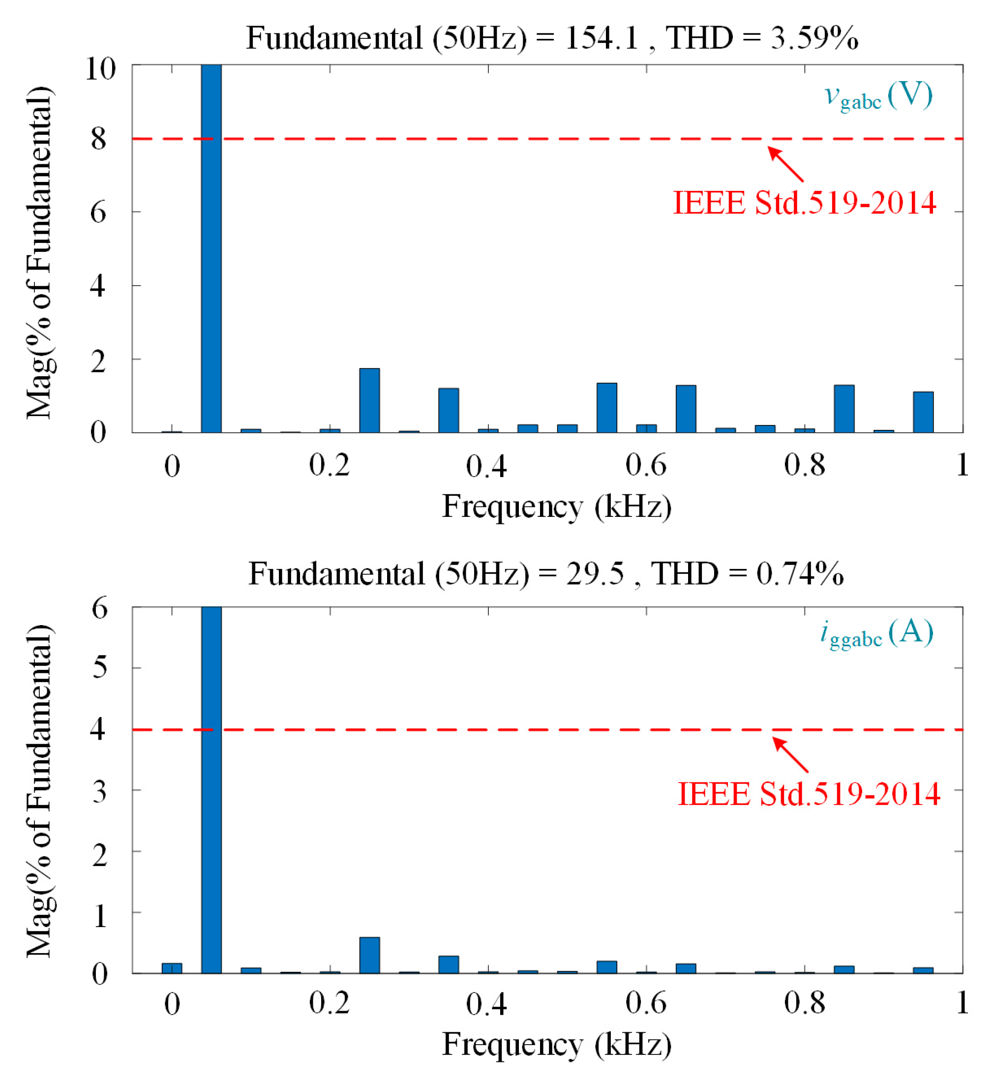
Figure 13 depicts the harmonic spectra of
vgabc and
iggabc, confirming the system’s compliance with IEEE Std. 519-2014. The PCC voltage exhibits a THD of 3.59%, remaining well within the allowable 8% limit, while the grid-injected current achieves an exceptionally low THD of 0.74%, far below the 4% threshold. These results highlight the effectiveness of the GFMC APF in harmonic suppression, ensuring high power quality by significantly reducing harmonic distortions compared to the unmitigated case shown in
Figure 9.
Figure 13.
Harmonic spectra of PCC voltages and grid currents under GFMC APF.
Figure 13.
Harmonic spectra of PCC voltages and grid currents under GFMC APF.
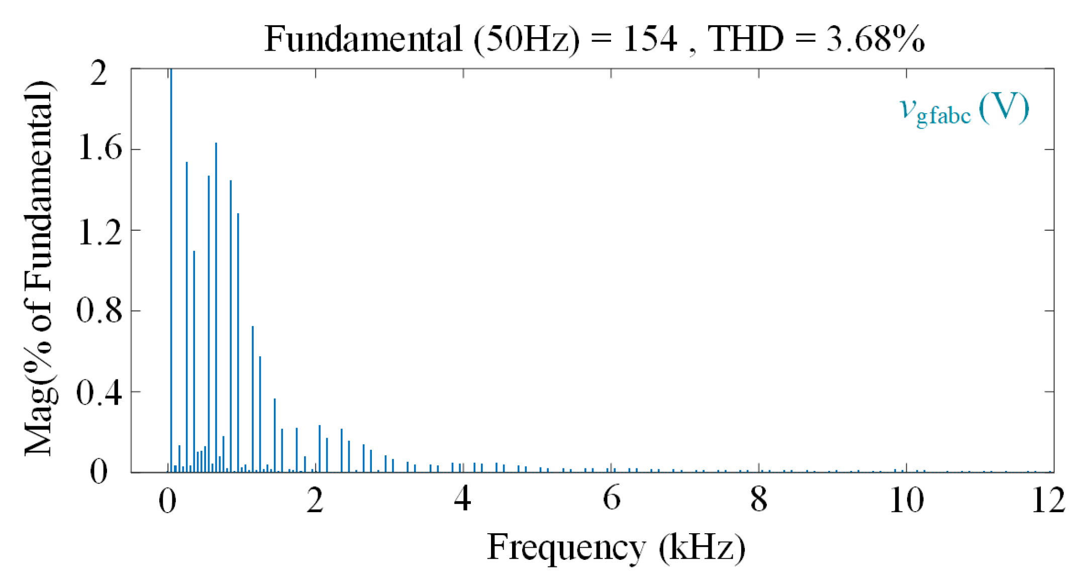
Figure 14 illustrates the harmonic spectra of the capacitor voltage
vgfabc in the GFMC APF during operation, emphasizing supraharmonic content. The graph shows the magnitude of the fundamental and harmonic components as a percentage of the fundamental voltage, extending up to 12 kHz. The THD is 3.68%, reflecting effective harmonic suppression. Focusing on supraharmonics, the spectrum reveals that harmonic magnitudes decrease sharply beyond 1 kHz, with minimal components between 2 kHz and 12 kHz. This indicates that the GFMC APF successfully limits supraharmonic emissions in this frequency range, maintaining low amplitudes relative to the fundamental.
Figure 14.
Harmonic spectra of capacitor voltages under GFMC APF.
Figure 14.
Harmonic spectra of capacitor voltages under GFMC APF.
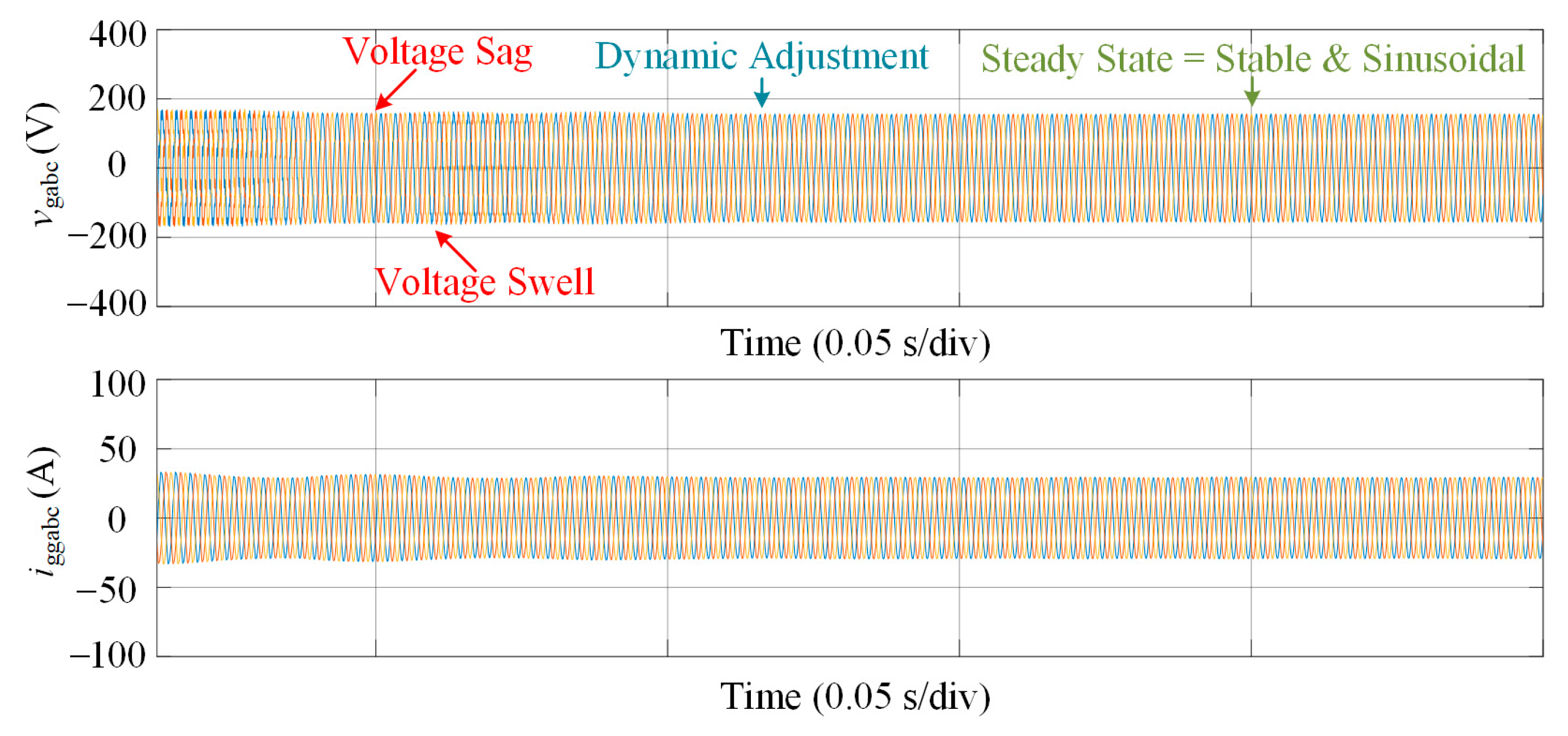
Figure 15 illustrates the response of the GFMC APF to non-stationary harmonic disturbances induced by variations in nonlinear load parameters. The top graph shows
vgabc, which undergoes a voltage sag followed by a voltage swell. Despite these transient variations, the waveform remains sinusoidal, demonstrating the GFMC APF’s capability to maintain voltage quality under time-varying operating conditions. The bottom graph presents
iggabc under the same scenario, which also remains stable and sinusoidal. These results demonstrate the effectiveness of the GFMC APF in suppressing harmonic distortion and maintaining high power quality in the presence of dynamic load changes.
Figure 15.
PCC voltages and grid-injected currents under non-stationary harmonic conditions.
Figure 15.
PCC voltages and grid-injected currents under non-stationary harmonic conditions.
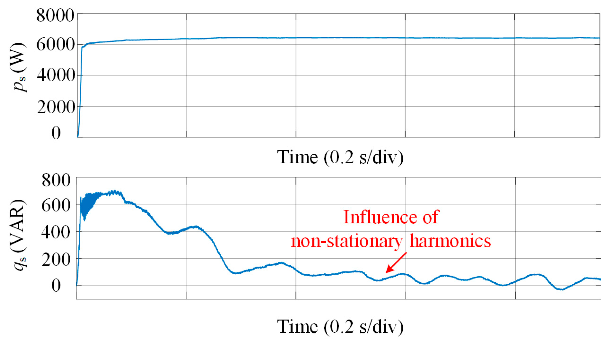
Figure 16 illustrates the active and reactive power dynamics of the GFMC APF under non-stationary harmonic conditions. The top graph displays the active power, which settles at approximately 6000 W after an initial transient, indicating effective power regulation in the presence of harmonic disturbances. The bottom graph shows the reactive power, which decreases from around 600 VAR to nearly zero, with transient fluctuations reflecting the impact of time-varying harmonic content. These results demonstrate the GFMC APF’s capability to regulate power flow and contribute to system-level stability under dynamic operating conditions.
Figure 16.
Active and reactive power dynamics under non-stationary harmonic conditions.
Figure 16.
Active and reactive power dynamics under non-stationary harmonic conditions.
