Article

Quasi-Uniform Density Non-Solid Infill Strategy for Axisymmetric Non-Planar Additive Manufacturing

by
Alvaro Guzman-Bautista
1,*,
Adrián López-Arrabal
1,
Elio Sanchez-Oro-Aguado
1,
Andrea Fernández Gorgojo
1,
Ramiro García-Galán
2,
Francisco J. Badesa
3 and
Antonio Vizan-Idoipe
1
1
Mechanical Engineering Department, ETSI Industriales, Universidad Politécnica de Madrid, 2, José Gutiérrez Abascal St., 28006 Madrid, Spain
2
Management Engineering Department, ETSI Industriales, Universidad Politécnica de Madrid, 2, José Gutiérrez Abascal St., 28006 Madrid, Spain
3
Center for Automation and Robotics (CAR) UPM-CSIC, Universidad Politécnica de Madrid, 2, José Gutiérrez Abascal St., 28006 Madrid, Spain
*
Author to whom correspondence should be addressed.
Appl. Sci. 2025, 15(11), 5899; https://doi.org/10.3390/app15115899
Submission received: 21 April 2025 / Revised: 16 May 2025 / Accepted: 22 May 2025 / Published: 23 May 2025
(This article belongs to the Section Additive Manufacturing Technologies)

Abstract

:

Featured Application

The methodology presented in this work is to be applied in Robot-based Non-Planar Additive Manufacturing processes, with a particular interest in material extrusion and directed energy deposition processes.

Abstract

Non-solid infill generation in Non-Planar Additive Manufacturing (NPAM) is still an open problem. This is due to mathematical complexities from curvature distortion, as well as bridging limitations inherent in some NPAM processes. Providing solutions to this problem may result in significant energy, build cycle time, and cost savings. In this context, the goal of this paper is to define a workflow for the generation of non-solid infill paths with quasi-uniform density within the layer. This was performed by defining the build geometry through an axisymmetric embedded map methodology, and the infill points were distributed via a geodesic repulsion energy-based algorithm. In addition to these core algorithms, several numeric optimizations were implemented to reduce runtime. The algorithm has been tested on several build platform geometries and slice polygons. The results were satisfactory, achieving a homogeneous kernel density distribution for all cases and reductions in geodesic distance standard deviations of around 70%. A first iteration of a path planning algorithm was also implemented to showcase the intended final results. This methodology is to be combined with other Design for Non-Planar Additive Manufacturing techniques to enable applications in the biomedical field, automotive and aerospace industry, or rapid mold manufacturing.

1. Introduction

Additive manufacturing (AM) has emerged as a transformative technology for producing complex geometries with high precision [1,2]. Nevertheless, traditional planar AM processes introduce inherent anisotropies in mechanical properties and limit geometric versatility. These planar layers limit the range of manufacturable parts, as they introduce significant anisotropy between the mechanical strength along the layer direction and the strength in the perpendicular direction. This effect is particularly pronounced in material extrusion (MEX) and directed energy deposition (DED) processes [3,4,5]. In response, Non-Planar Additive Manufacturing (NPAM) has gained increasing attention as a methodology for forming structures from additively deposited curved layers [6,7]. Once stacked, non-planar layers enhance structural integrity, surface quality, and material efficiency. NPAM allows for local variations in layer deposition direction, optimizing mechanical properties, increasing fatigue life, and reducing the stair-stepping effect studied for planar slicing techniques [8,9,10].
The development of NPAM led to the rise of robotic systems that, by adding degrees of freedom to the end effector, enable material deposition in multiple directions. This is a technique known as Robot-based Non-Planar Additive Manufacturing (RbNPAM) [11]. This approach addresses the limitations of traditional additive manufacturing machines, and opens new possibilities for complex geometries, enhanced surface finishes, and optimized part performance in multiple applications [12,13]. Despite these advantages, systematic methodologies for non-planar slicing and infill generation remain an open research problem [14,15].
The first challenge in the field of non-planar layer path generation is the definition of non-planar layers. Various research studies aim to define non-planar layers by varying the z-coordinate in traditional additive manufacturing machines [16,17]. Additionally, building on planes with a small angular offset is used to produce geometries with planar layers in different orientations [18]. Alternatively, curved xy grids have been proved to work for some specific cases [19]. Other authors have explored the use of isothermal curves and maximum local stress-oriented surfaces [20,21]. However, the use of non-Cartesian coordinate systems like polar or spherical coordinates [22,23,24], as well as helicoidal [25], can be observed to facilitate the generation of such surfaces. These methods, which may be called embedded map methods, become more complex when attempting to generalize the problem to parametrically defined layers while becoming more versatile.
Curving the build surfaces introduces a distortion of the Cartesian space in the embedded map, making it challenging to handle using traditional methods found in commercial slicers for Planar Additive Manufacturing [26]. Within an embedded map, the surface curvature distorts the deposited material’s line thickness and alters the distance between target points along the toolpath, significantly complicating the development of infill patterns. Additionally, it exacerbates the issues already analyzed in the literature regarding the occurrence of voids in infill patterns [27].
Non-solid infill strategies have been extensively studied in the context of planar AM, owing to their benefits in terms of material, build cycle time, cost, and energy savings [28]. Common approaches to non-solid infill generation include the use of contouring combined with spiral or Hilbert curve techniques [29,30,31,32]. Other studies propose maze infill strategies [33] or adaptive filling based on local density requirements [34]. Additionally, there have been pixel-based approaches where pixel size is defined by the mesh point distortion [35,36]. Even so, no algorithm has yet been developed to adapt way-points density to non-planar surfaces. Achieving this would enable all current planar non-solid infill strategies to be applied in the NPAM context, including the use of more advanced infill techniques such as Triply Periodic Minimal Surfaces.
A Triply Periodic Minimal Surface is a type of non-intersecting surface, often embedded in a base cell. TPMS base cells have symmetry properties akin to crystallographic groups that make them ideal for pattern repetitions. TPMS have gained significant attention as infill patterns in additive manufacturing due to their unique combination of mechanical performance and material efficiency [37]. TPMS structures, characterized by their smooth, continuous surfaces and minimal surface area for a given volume, provide exceptional strength-to-weight ratios and isotropic mechanical properties [38,39]. Additionally, their complex geometries improve heat dissipation and fluid flow, making them particularly advantageous in applications such as lightweight structural components, biomedical implants, and heat exchangers [40,41,42].
Despite their potential, these surfaces have not yet been adapted to NPAM due to the distortion of the Cartesian space. This limitation presents an open research opportunity to integrate the advantages of TPMS (and generally, non-solid infills) into this advanced manufacturing methodology [43]. The continued development of additive manufacturing technologies creates an inherent need for a generalized slicing and layer infill methodology. This approach should extend the principles of design for additive manufacturing—meaning the integration of material properties with specific geometries and build directions—to NPAM, unlocking all its potential advantages [44].
In this context, the objective of this paper is to define and optimize a procedure for the generation of non-solid infill paths with quasi-uniform density within the layer. The main contributions of this paper lie in the development and optimization of a repulsion force-based algorithm for geodesically uniform mesh generation, as well as infill path planning on axisymmetric build platforms. These contributions are enabled by the generalized definition of embedded maps for axisymmetric build platforms previously provided by the authors [45], which rely on parameterized curves serving as generatrices for build platforms. Additionally, this work aims to advance the generalization of non-solid infill strategies for non-planar fillings with deformation associated with curvature.
This methodology is intended to be used in MEX and DED processes to reduce feedstock and energy consumption, as well as cycle time and cost. Such improvements are highly valued in industrial sectors that manufacture high added value components, such as biomedical, aerospace, automotive, robotics, energy, and consumer electronics [46,47,48,49,50].

2. Methodology

The methodology aims to create non-solid infill paths of homogeneous density for NPAM, employing an axisymmetric slicing approach with an embedded map. Figure 1 schematically depicts the workflow. First, a sufficiently smooth axisymmetric build platform is defined (Section 2.1), ensuring that the resulting surface is a Riemannian manifold with differentiable curvature. Next, a geodesic repulsion energy algorithm distributes points uniformly across each slice (Section 2.2). The number of points is based on manufacturing parameters that can be adjusted by the user, namely, command infill density, infill pattern, and line width. Additionally, this repulsion energy algorithm requires the introduction of several numerical optimizations to achieve practical runtimes (Section 2.3). Once the points are positioned, a path planning routine (Section 2.4) generates continuous trajectories that can be executed by a robot-based NPAM machine. Finally, the uniform density hypothesis is verified using kernel density estimations and distance histograms (Section 2.5). Three case studies on two different build platforms are used to demonstrate the method versatility (Section 2.6).

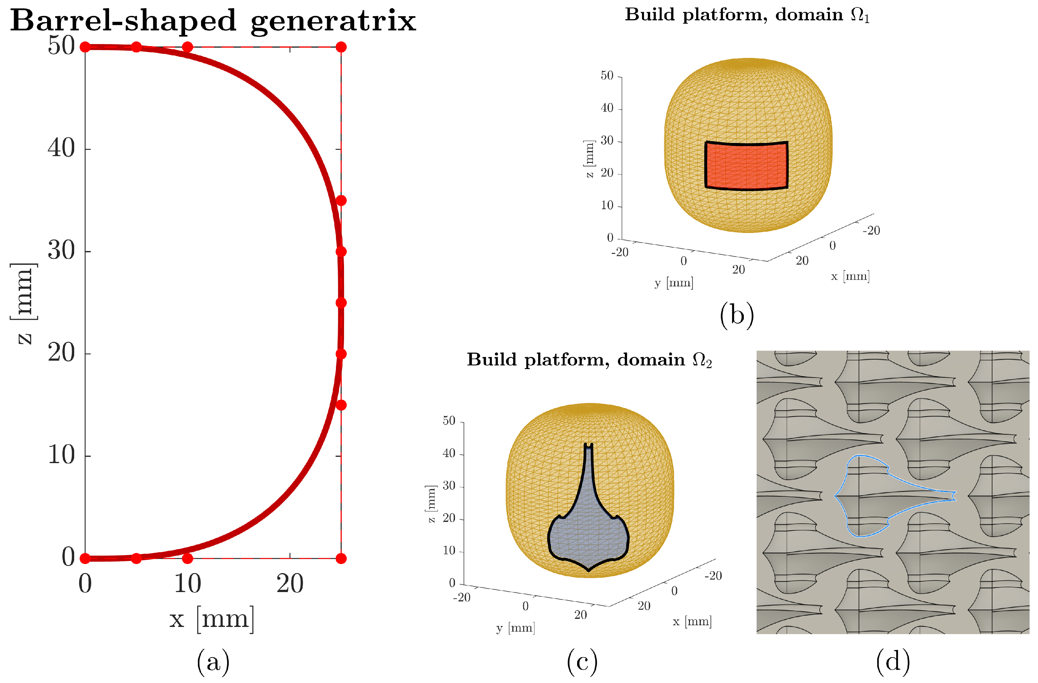
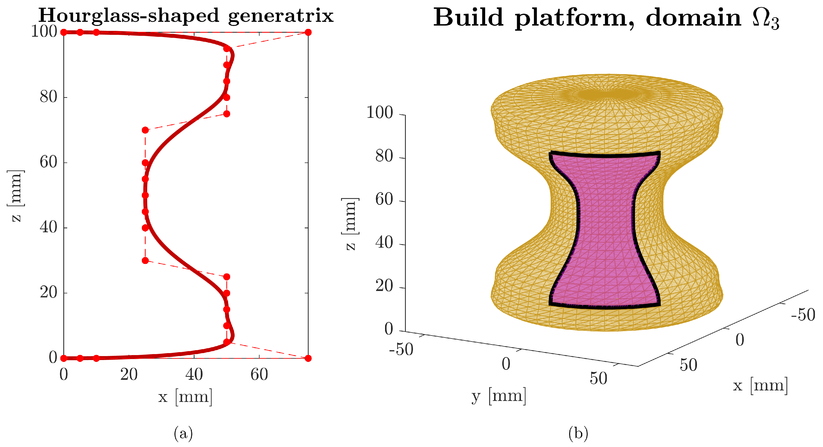
2.1. Defining a Sufficiently Smooth Build Platform

The first requirement for generating quasi-uniform infill is the definition of a smooth, axisymmetric build platform via the revolution of a suitable generatrix curve. Following [45], the Cartesian coordinates { x , y , z } of the platform are expressed by an embedded map r M ( u , θ ) , where u parameterizes the generatrix spline and θ is the angle of revolution. In this work, each generatrix is constructed by degree-six Bézier spline compositions. These curves are chosen owing to their C 3 continuity at the knots, while meeting perpendicularity requirements at the revolution axis without loss of generality. Lastly, to ensure that the resulting surface is as a Riemannian manifold, generatrices should be absent of cusps or self-intersections. These conditions are central for supporting the geodesic-based approach used for infill generation, since they equip the build platforms with sufficiently differentiable metric tensor components and Christoffel symbols.

2.2. Uniformly Meshing a Riemannian Manifold

To generate uniform density non-solid infills, it is necessary to create a uniform distribution of points that account for build platform curvature. Additionally, the number of points N to distribute must be determined based on process parameters selected by the user, namely, command infill density, infill pattern, and line width. Both challenges may be addressed utilizing Riemannian geometry concepts.
First, uniformly distributing points on a Riemannian manifold requires a metric that accommodates local curvature. In this work, each slice is uniformly populated by means of a geodesic repulsion energy algorithm (GRE). Every pair of points ( i , j ) is associated with a potential E i j = d i j g e o m , where d i j g e o is the geodesic distance between points i and j, and m > 1 is a penalizing coefficient (in this work, m = 5 to highly penalize close pairs of points). Summing over all non-repeating pairs yields a total mesh energy E. The algorithm iteratively adjusts point positions to minimize E by displacing each point along the direction defined by the repulsion force F i = Σ E i j .
Since the pair-wise geodesic distance must be determined, the manifold metric tensor g and Christoffel symbols of the second kind Γ j k i are required. Points { u i , θ i } and { u j , θ j } in the embedded map are connected by the shortest path governed by a second-order ordinary differential Equation (1), with boundary conditions (2). Solving this equation and integrating along a parameter, τ in (3), yields the geodesic distance, which replaces Euclidean measures in the repulsion potential. Although this approach is computationally more complex, it adapts the distribution to the manifold intrinsic curvature and avoids clustering in regions of negative curvature.
{ u ¨ = Γ u u u ( u ˙ ) 2 Γ θ θ u ( θ ˙ ) 2 θ ¨ = 2 Γ u θ θ u ˙ θ ˙
{ G i j ( τ = 0 ) = { u 0 , θ 0 } = { u i , θ i } G i j ( τ = 1 ) = { u 1 , θ 1 } = { u j , θ j }
d i j g e o = 0 1 g u u G ˙ i j u ( τ ) + g θ θ G ˙ i j θ ( τ ) d τ
Second, the number of points N for each slice is determined by the area A Σ of the domain in the embedded map, the command infill density ρ c , the Cartesian nominal line width e, and the number of equi-angled lines n that pass through each point. This n parameter depends on the infill pattern. This number of points may be simplified to (4), considering the worst-case infilling scenario, where each of the equi-angled n rasters traversing a point covers the least area around it. This relationship provides a direct means to estimate the mesh number of points in the infill by adjusting ρ c , while also considering the desired line width and complexity of the path pattern.
N = A Σ ρ c 2 n 2 e 2
The meshing procedure begins by scattering N points within the parameter domain Ω , which corresponds to the slice polygon. These initial placements can come from random sampling or more refined strategies. A subsequent repulsion–minimization stage updates each point’s location by applying the forces F i derived from E . When changes in point positions or overall energy become negligible, the algorithm terminates, leaving a near-uniform distribution that reflects the manifold curvature.

2.3. Numerically Optimizing the Algorithm

Implementing the repulsion energy method on a curved manifold is computationally demanding because each energy evaluation involves solving for geodesic distances and repulsion forces. Several measures are introduced to mitigate this cost while preserving the algorithm’s reliability. The first approach is the explicit approximation of the repulsion forces. Rather than numerically calculating gradients by evaluating the potential in the vicinity of each point, a chord-length discretization (5) is employed to approximate geodesic curves and estimate the gradient. This approximation substantially reduces the frequency with which the geodesic equation is solved, improving runtimes.
d i j u d i j θ k = 1 n 1 G ( u ( τ k + 1 ) , θ ( τ k + 1 ) ) G ( u ( τ k ) , θ ( τ k ) ) G ( u ( τ k + 1 ) , θ ( τ k + 1 ) ) G ( u ( τ k ) , θ ( τ k ) ) { c } S ( τ k )
The second approach is the non-dimensionalization of both the total energy and the forces by their initial values, denoted as E 0 and F 0 . This normalization alleviates the stiffness of the potential function and aids convergence. Without such scaling, small point displacements can trigger disproportionately large variations in the energy gradient, potentially halting the optimization.
The third and last approach is the selection of a close-to-solution initial seed distribution. While a random seed may suffice in principle, three alternative methods may provide more favorable starting configurations that typically converge more rapidly. A geodesic blue noise sampling approach (GBNS) filters randomly generated points by imposing minimum geodesic distances, thereby yielding a distribution already aligned with the manifold curvature [51,52]. A second possibility treats the manifold as approximately flat by using Euclidean repulsion energy (ERE) to position points. Although this imposes a degree of geometric simplification, it is often faster to compute, and allows for non-linear mesh restrictions such as non-rectangular slice polygons. A third option employs Euclidean blue noise sampling (EBNS), which similarly maintains minimum distances using a Euclidean metric rather than the full geodesic one. These refined initializations help the subsequent geodesic repulsion algorithm initialize closer to the solution, providing significant time savings.
Collectively, these optimizations ensure that point placement converges more reliably and in practical runtimes, even for build platforms characterized by complex curvature.

2.4. Generating Infill Paths

After a uniform point distribution is achieved, a path planning algorithm connects these points to form sets of continuous Hamiltonian paths. This study applies a simple nearest neighbor heuristic combined with a 2-opt procedure to remove self-intersections and reduce path length [53]. The geodesic equation is then solved segment by segment to respect the manifold’s curvature, resulting in conformal paths that may be performed by the robot-based NPAM machine. Although more sophisticated algorithms can be employed to address dynamic performance or machine-specific constraints [54], this approach aims to illustrate the viability of geodesic non-solid infill path generation.

2.5. Validating the Uniform Density Hypothesis

To verify that the final distribution achieves a quasi-uniform density, two indicators are used: the kernel density function (KDF) and the mean distance histograms.
The KDF metric [55,56] assigns each point i a local density ρ i = j i W i j , with W i j defined via a smooth kernel of radius h = 4 ( n e / ρ c ) as per (6). This h value may be approximated to four times the mean distance between points. A well-distributed mesh exhibits consistent ρ i values, differing only at vertices or boundaries.
W i j = 15 π h 6 { ( h d i j g e o ) 3 , 0 d i j g e o h 0 , d i j g e o > h
On the other hand, the mean distance histogram metric aims to further characterize the density uniformity. For each point, the distances to its 2 n nearest neighbors are compiled, yielding a distribution whose standard deviation reflects how evenly spaced the points are depending on the infill pattern.

2.6. Case Study Definition

The methodology is demonstrated on a barrel-shaped platform (with two domains, Ω 1 and Ω 2 ) and an hourglass-shaped platform (domain Ω 3 ). The infilling parameters for each domain, as well as the initial seed method used, are summarized in Table 1. The barrel geometry is representative of a non-negative curvature along { u , θ } , while the hourglass platform involves both positive and negative curvatures. The control polygons for each platform are presented in Table 2 and Table 3. Each domain is examined by computing the platform generatrix continuity, metric tensor, and Christoffel symbols, and then applying the geodesic repulsion energy algorithm. Lastly, a path planning example is provided to illustrate how the final point distributions can be turned into feasible infill trajectories for robot-based NPAM processes. Figure 2 and Figure 3 depict these platforms and their respective domains.

3. Results and Discussion

Below are the results of applying the present methodology onto the three case studies presented. This section includes a collection of insights regarding generatrix continuity and its effects on geodesic magnitudes, the resulting distribution of points after applying the GRE algorithm and a discussion of the metrics previously outlined, a runtime comparison of the three initial seed methods on Ω 3 , and lastly, an example of infill raster generation for all three case studies.

3.1. Generatrix Definition, Continuity, and Geodesics

The continuity requirements proposed in Section 2.1 are satisfied by all build platform geometries through the use of degree-six Bézier spline compositions for their generatrices. Both generatrices, together with their first three derivatives S ˙ , S ¨ , S and curvature κ , present sufficient continuity at the spline knots. This fact confirms that the curvature is differentiable and demonstrates that the build platforms are Riemannian manifolds. In turn, this enables the differentiability required for feasible and efficient geodesic path computations in NPAM trajectory planning.
This is further substantiated through the analysis of the curvature κ , the metric tensor components g i j , and the Christoffel symbols Γ j k i . Figure 4 presents these three magnitudes for the hourglass build platform, the more complex of the two. The C 3 nature of the spline composition is verified by the smoothness of the curvature and all non-zero symbols. Of note, the curvature is non-constant, with both positive and negative regions. This implicitly validates the methodology for a wide range of curvature values of any given build platform. Additionally, this smoothness allows for a stable resolution of the geodesic equation throughout the domain except near the poles, where g θ θ 0 and Γ u θ θ . This is caused by the loss of invertibility of the metric tensor around the poles. Therefore, these polar regions should be avoided for stable geodesic path calculations, and result in a suitable area for the mechanical interface of the end effector with the robotic manipulator.

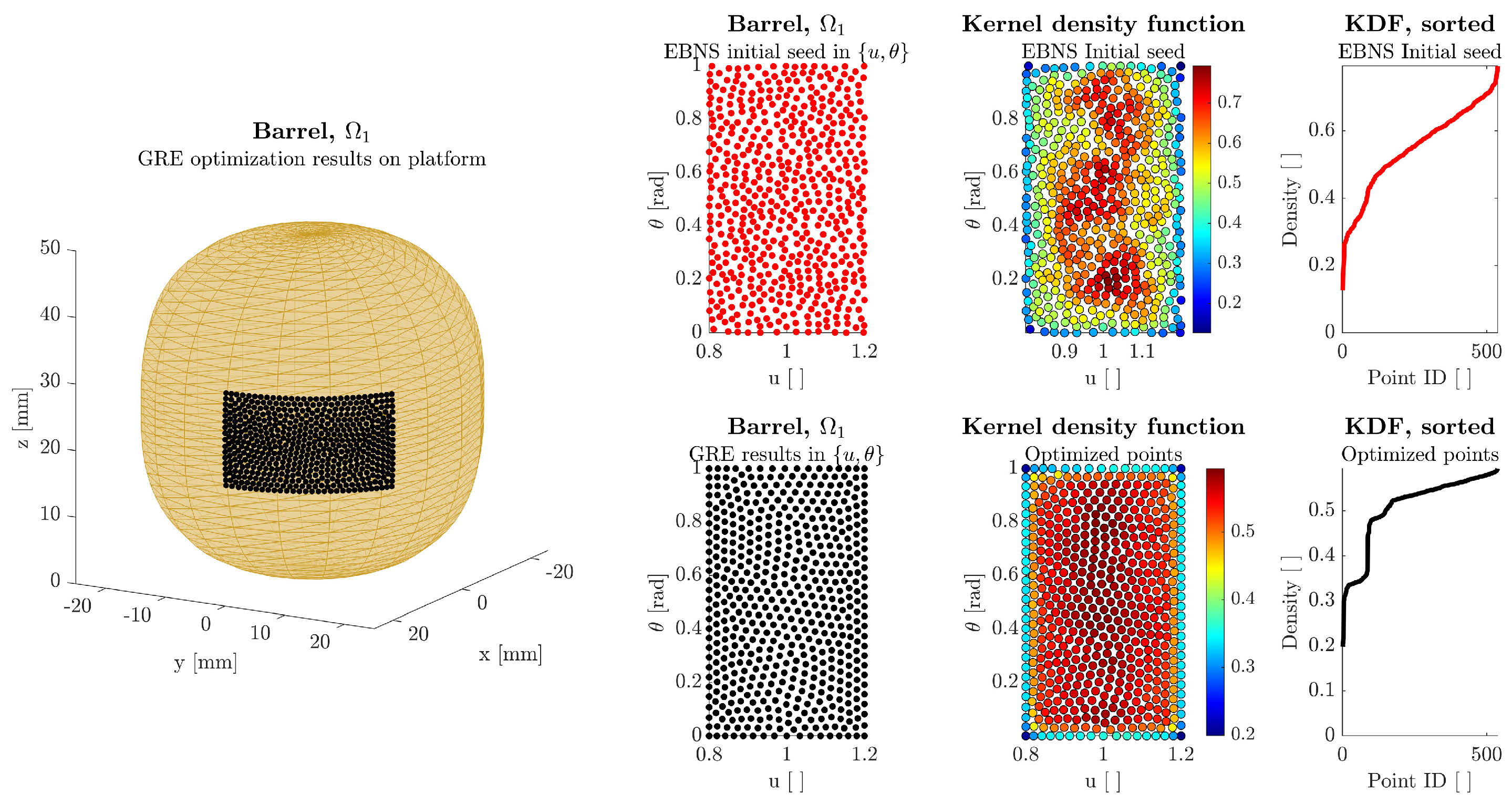
3.2. Results of the Repulsion Energy Minimization Algorithm and Validation of the Uniform Density Hypothesis

The proposed geodesic repulsion energy algorithm demonstrated its capacity to distribute points uniformly on both barrel-shaped and hourglass-shaped surfaces. The case Ω 1 , with u [ 0.8 , 1.2 ] , θ [ 0 , 1 ] , and ρ c = 50 % ( n = 1 , N = 538 ), was initialized via EBNS owing to the large number of points N. Figure 5 represents the GRE-optimized distribution of points on the left-hand side of the figure, whereas the right-hand side graphs indicate the distribution in the embedded map, the KDF evaluation for each point, and the values of KDF sorted in ascending order for both the EBNS initial seed and the GRE optimized distribution.
The embedded map distribution shows a noticeable improvement in point homogeneity, which is further supported by the KDF evaluation for each point. This implies that a path generated through these points will retain a mean infill density close to command. Additionally, this methodology enables the creation of quasi-uniform infill densities across any given layer, introducing or removing points according to the slice total area A Σ . The sorted KDF function also validates the quasi-uniform hypothesis, as it is possible to differentiate three regions: the vertices, the domain boundary, and the interior. After applying GRE, each of these regions is separated from each other by means of a noticeable increase in kernel density function, a behavior not observed in the EBNS initial seed distribution.
The second case study Ω 2 in the same barrel geometry featured ρ c = 25 % ( n = 1 , N = 173 ) and a non-rectangular slice boundary, with concave and convex areas. To solve this, the ERE initial seed algorithm was used, combined with a non-linear constraint to force all points towards the interior of the slice polygon. Even with a less favorable initial seed from the Euclidean repulsion energy method, the geodesic algorithm still converged to a quasi-uniform distribution (Figure 6), though concave boundary regions (close to u = 0.5 ) proved more challenging. In this case, the three regions in the sorted KDF cannot be discerned from each other, as the polygon does not include defined vertices. For the hourglass platform, a domain Ω 3 with u [ 1 , 3 ] , θ [ 0 , 1 ] , and ρ c = 10 % ( n = 1 , N = 204 ) was tested using multiple initial seeds. Figure 7 shows the geodesic blue noise sampling and the corresponding final distribution, confirming the GRE algorithm ability to compensate for concave curvatures at u 2 and achieve nearly uniform densities despite the platform’s varying cross-sectional areas.
Regarding the distance histograms, Figure 8 shows the distance with the 2 n = 2 nearest neighbors. The resulting Gaussian distributions can be represented by the values for mean and standard deviation depicted in Table 4. All three cases show a significant decrease in standard deviation in all cases, with a 71.7% reduction for Ω 1 , a 71.6% reduction for Ω 2 , and a 44% reduction for Ω 3 . This aligns with the expected result, where the GBNS initial seed algorithm was estimated to provide the most close-to-solution distribution before GRE optimization. The mean values confirm that the GRE methodology provides distributions with densities close to the command. This can be estimated by means of the ratio line width to mean distance ( r a t i o = e / μ ^ [ % ] ). This ratio is equal to 47.2% for Ω 1 , 23.6% for Ω 2 , and 9.1% for Ω 3 (compared with command densities of 50%, 25%, and 10%, respectively).

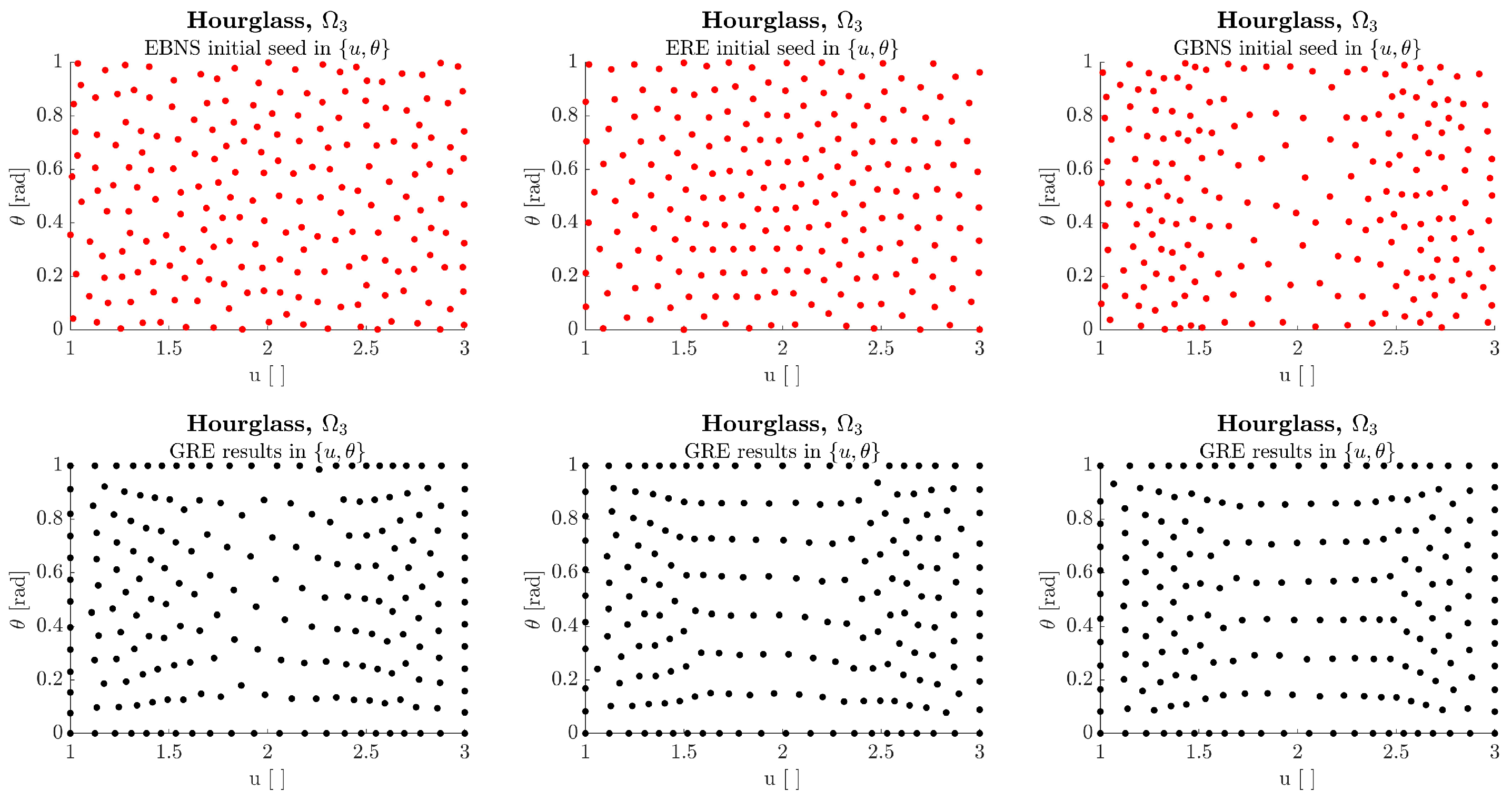
3.3. Comparison of Initial Seed Methods

Although the barrel-based domains mainly relied on one initial seed approach each (EBNS for Ω 1 , ERE for Ω 2 ), the hourglass domain Ω 3 served to compare the three methods in a controlled manner: Euclidean blue noise sampling, Euclidean repulsion energy, and geodesic blue noise sampling, aiming to distribute N = 204 points. In all trials, 50 iterations of GRE optimization were performed after the initial seed. Regarding runtimes, the procedure utilizing EBNS elapsed 2425.2 [s], the ERE-based procedure elapsed 3407.9 [s], and the GBNS-based procedure elapsed 6123.8 [s]. On the other hand, the final standard deviations after GRE were σ Ω 3 E B N S o p t = 0.340 [mm], σ Ω 3 E R E o p t = 0.284 [mm], and σ Ω 3 G B N S o p t = 0.278 [mm]. These results equip the user with the possibility of deciding with a more accurate result at the cost of runtime in the form of GBNS, a compromise solution in the form of ERE, or a fast solution at the expense of accuracy in the form of EBNS. Figure 9 further exemplifies this, showcasing the initial seed and final distributions for all three subcases.
These runtime results are valuable in the context of manufacturing offline process set-up. One of the goals of this offline process setup is to asynchronize the offline setup tasks from the operation proper, leaving no machine idle time. This allows for significant build cycle time savings and efficient manufacturing job shop planning. This asynchronization can be achieved through the present methodology, as the trajectory planning algorithm runtimes are in the order of magnitude of the build cycle time of a layer, especially in robot-based NPAM [58].

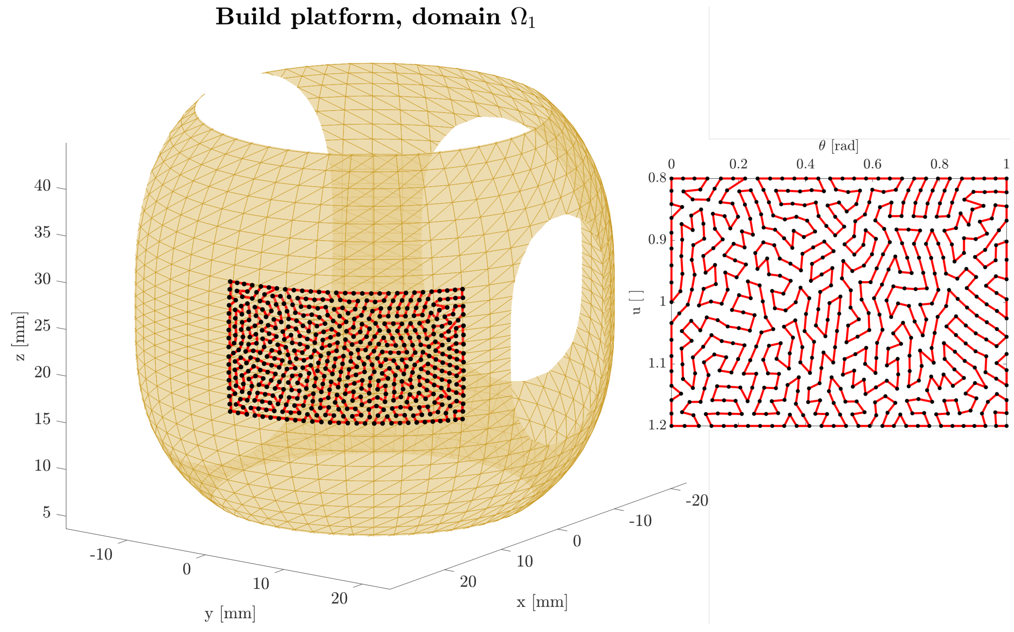
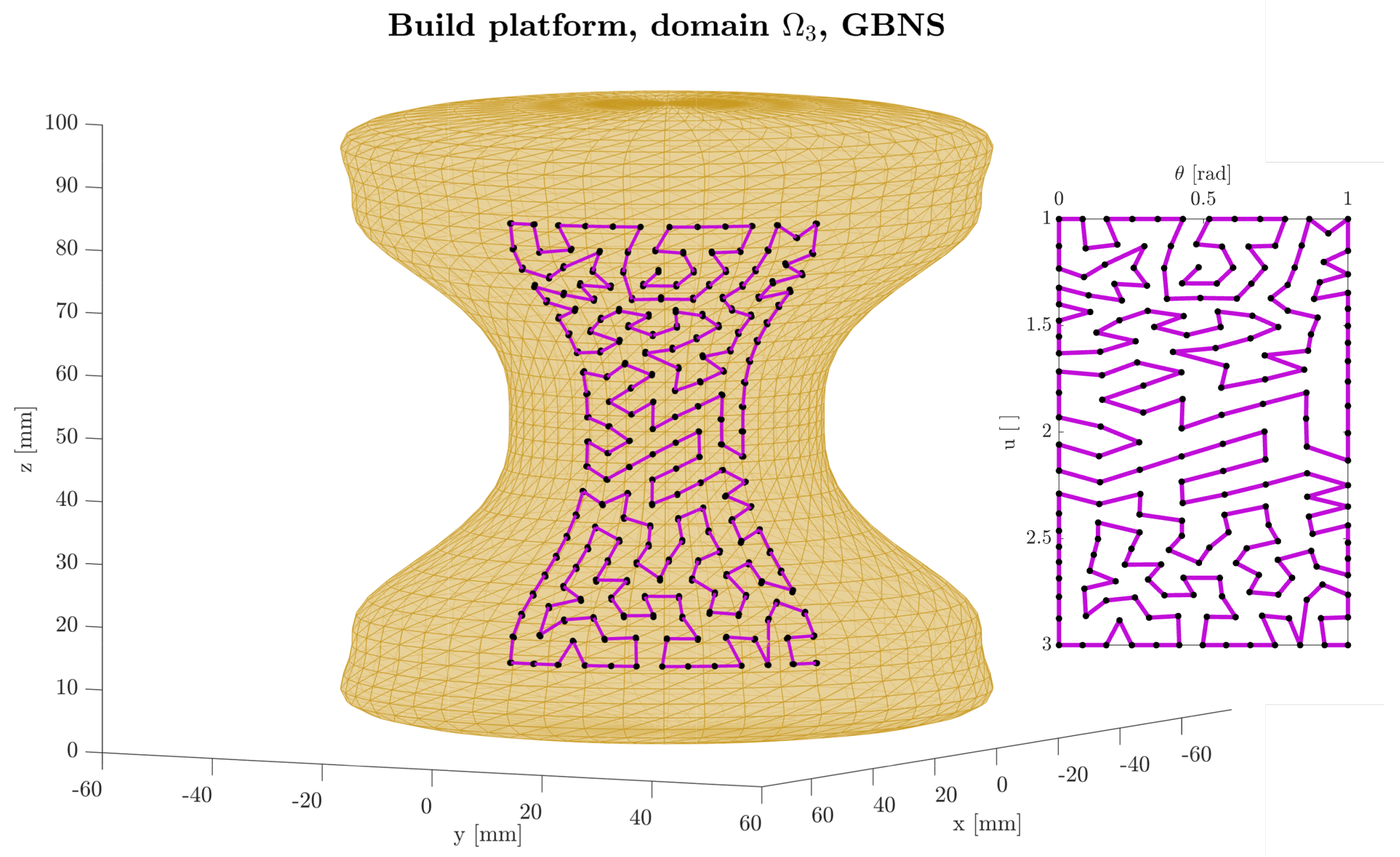
3.4. Path Planning Examples with the 2-Opt Nearest Neighbor Algorithm

Several final point distributions obtained by the above optimization were further employed to illustrate infill path planning through the geodesic 2-opt nearest neighbor heuristic. In Figure 10, Figure 11 and Figure 12, the results show smoothly connected Hamiltonian paths across all distributed points for Ω 1 , Ω 2 , and Ω 3 (GBNS seed), respectively.
In all the examples presented, the trajectory starting point was a slice polygon vertex (the bottom-right corner in Ω 1 and Ω 3 and the bottom vertex in Ω 2 ). However, the starting point can be chosen according to other criteria. The present infill algorithm is to be embedded within a complete slicing algorithm, which includes walls and infill. Usually, this implies that the infill phase is done after the wall phase. In this kind of situation, the infill start point can be located close to the wall end point, shortening build cycle times. Other situations may include slice polygons without vertices. In any case, the algorithm can be initialized from any point, without the risk of generating an unsuitable trajectory.
Additionally, this path planning strategy could be extended and refined to address functionality requirements such as optimizing fatigue performance [10,59], optimizing internal support creation [25], reducing build cycle time [60], or increasing mechanical strength [16]. Other research lines may include the definition of functionally graded structures through non-uniform infill densities [61] or incorporating machine dynamics onto the path planning [54], optimizing the overall build efficiency for robot-based NPAM processes.

4. Conclusions

The present paper introduces a novel methodology to generate non-solid uniformly dense infill patterns given a slice geometry. This slice geometry will be defined in an embedded map for a given manifold. In this regard, a previous parameterization performed by the authors was used to create both the build platform and the embedded map, utilizing degree-six Bézier splines. The methodology performs better if the build platform fulfills certain conditions on continuity and complexity, as it allows for the analytic calculation of the metric tensor components and the Christoffel symbols of the second kind. To demonstrate this methodology, three increasingly complex domains and build platforms were analyzed.
Using the topology concepts outlined above, an algorithm to create uniformly dense point distributions was created, based on the geodesic repulsion force among points. The algorithm shows good performance in terms of homogeneity of the kernel density function, and it is further supported by the distance histograms for all the three case studies presented. This uniformly dense mesh can be correlated with the maximum overhang and bridge distance inherent to AM processes, and allows the user to select a command infill density of their choice. This command infill density may be selected based on factors such as build time, mechanical strength, and others.
In addition, a first iteration of a path planning algorithm was presented, generating rasters among points in a non-self-intersecting, Hamiltonian fashion. This path planning method serves as a means of visualization, and showcases the potential of the methodology. The path planning outlined in this work is a basic implementation, and as such, there is room for improvement. Among the identified improvements, there is implementation for non-simple slice polygons (i.e., slices with holes), as well as optimizing and smoothing the rasters for the best AM machine dynamic performance.
Another limitation found in this study is the overall runtime of the presented algorithms. Although a great effort has been made to optimize the initial seeds to provide the algorithm with close-to-solution distributions, the geodesic repulsion algorithm inevitably needs to compute many solutions for the geodesic differential equation. This could be solved by utilizing other parameterizations of curves, which offer an analytical solution for the geodesic equation, or exploring the benefits of Neural Operators to solve the geodesic equation.
Despite these limitations, the methodology is versatile, and their concepts may be extended to more sophisticated infill methods, such as volumetric lattice infills based on TPMS [43]. This type of infill may also account for part anisotropy as a function of load directions, and can also be combined with the present non-solid, uniform density conformal infill generation method. Accommodating for these types of infill generation would imply the generalization of the geodesics to the complete isomorphism between the embedded map and the manifold in the ambient Cartesian space R 3 .
The methodology accommodates for all values of curvature, either positive or negative, as long as some considerations are taken into account. For negative curvature regions, there is an implicit limit in design freedom, as not all parts may have a bijective homeomorphism through the embedded map. In addition, negative curvature regions pose a challenge in terms of practical implementation on an NPAM robotized station. Wrongly adjusted parameters such as nozzle diameter, nozzle angle, or station configuration may induce clashes between the build platform and the station. In this regard, there is a lack of knowledge in the context of embedded map NPAM slicing that needs to be addressed.
Overall, the procedure outlined in this work enables the possibility of quasi-homogeneous density infills for NPAM, while retaining the uniform slicing characteristic from embedded map methods. However, it is not constrained to this specific field of manufacturing processes, since it may be extrapolable to other processes based on material deposition such as micropatterning. This is considered to be relevant in the context of high added value parts in the biomedical context, the automotive or aerospace industries, or fast mold manufacturing. Lastly, this methodology is fully compatible with robot-based workflows. The methodology also allows for mechanical properties design when working conjointly with other designs for NPAM or general AM techniques, such as automatic conformal slicing, multi-material manufacturing, or direct assemblies, among others.

Author Contributions

Conceptualization, A.G.-B., A.L.-A. and A.V.-I.; methodology, A.G.-B., E.S.-O.-A. and R.G.-G.; software, A.G.-B., E.S.-O.-A. and R.G.-G.; validation, A.F.G. and R.G.-G.; formal analysis, A.G.-B.; investigation, A.L.-A. and A.F.G.; data curation, E.S.-O.-A.; writing—original draft preparation, A.G.-B. and A.L.-A., writing—review and editing, A.F.G., R.G.-G., F.J.B. and A.V.-I.; supervision, A.V.-I.; project administration, F.J.B.; funding acquisition, A.F.G. and F.J.B. All authors have read and agreed to the published version of the manuscript.

Funding

This work was supported by the Spanish Ministry of Science and Innovation under Grant number CPP2023-010651.

Institutional Review Board Statement

Not applicable.

Informed Consent Statement

Not applicable.

Data Availability Statement

The original data presented in this study are openly available in Zenodo at http://doi.org/10.5281/zenodo.15224948.

Conflicts of Interest

The authors report that there are no competing interests to declare. The funders had no role in the design of the study; in the collection, analyses, or interpretation of data; in the writing of the manuscript; or in the decision to publish the results.

Abbreviations

The following abbreviations are used in this manuscript:
AMadditive manufacturing
MEXmaterial extrusion
DEDdirected energy deposition
NPAMNon-Planar Additive Manufacturing
RbNPAMRobot-based Non-Planar Additive Manufacturing
TPMSsTriply Periodic Minimal Surfaces
GREgeodesic repulsion energy
GBNSgeodesic blue noise sampling
EREEuclidean repulsion energy
EBNSEuclidean blue noise sampling
KDFkernel density function

References

  1. Kanishka, K.; Acherjee, B. Revolutionizing manufacturing: A comprehensive overview of additive manufacturing processes, materials, developments, and challenges. J. Manuf. Process. 2023, 107, 574–619. [Google Scholar] [CrossRef]
  2. ISO/ASTM Standard 52900:2021(E); Additive Manufacturing—General Principles—Fundamentals and Vocabulary. 2021. Available online: https://www.iso.org/obp/ui/#iso:std:iso-astm:52900:ed-2:v1:en (accessed on 15 February 2025).
  3. Ahn, D.G. Directed Energy Deposition (DED) Process: State of the Art. Int. J. Precis. Eng. Manuf.-Green Technol. 2021, 8, 703–742. [Google Scholar] [CrossRef]
  4. Wang, Y.; Ding, Y.; Yu, K.; Dong, G. Innovative polymer-based composite materials in additive manufacturing: A review of methods, materials, and applications. Polym. Compos. 2024, 45, 15389–15420. [Google Scholar] [CrossRef]
  5. Forés-Garriga, A.; Pérez, M.A.; Gómez-Gras, G.; Reyes-Pozo, G. Role of infill parameters on the mechanical performance and weight reduction of PEI Ultem processed by FFF. Mater. Des. 2020, 193, 108810. [Google Scholar] [CrossRef]
  6. Tang, P.; Zhao, X.; Shi, H.; Hu, B.; Ding, J.; Yang, B.; Xu, W. A review of multi-axis additive manufacturing: Potential, opportunity and challenge. Addit. Manuf. 2024, 83, 104075. [Google Scholar] [CrossRef]
  7. Urhal, P.; Weightman, A.; Diver, C.; Bartolo, P. Robot assisted additive manufacturing: A review. Robot. Comput.-Integr. Manuf. 2019, 59, 335–345. [Google Scholar] [CrossRef]
  8. Stano, G.; Sayah, N.; Smith, D.E.; Fleck, T.J. Effect of Process Parameters in Additively Manufactured Sensors prepared via Material Extrusion Processes: Correlation among Electrical, Mechanical and Microstructure Properties. Addit. Manuf. Lett. 2024, 9, 100194. [Google Scholar] [CrossRef]
  9. Ballesteros, L.M.; Cano, D.; García, C.A.; Giraldo, L.V.; Jiménez, L.F.; Rave, E.; Rudas, J.S.; M, C.A.I.; Toro, A. Comparison of textured nylon surfaces manufactured by CNC micromachining and 3D printing. Surf. Topogr. Metrol. Prop. 2024, 12, 012001. [Google Scholar] [CrossRef]
  10. Bakhtiari, H.; Aamir, M.; Tolouei-Rad, M. Effect of 3D Printing Parameters on the Fatigue Properties of Parts Manufactured by Fused Filament Fabrication: A Review. Appl. Sci. 2023, 13, 904. [Google Scholar] [CrossRef]
  11. Tunc, L.T.; Sheikhi, M.; Moldovan, C.; Gutiu, E.; Balc, N. Non-planar 5-axis directional additive manufacturing of plastics: Machine, process, and tool path. Manuf. Lett. 2024, 41, 959–964. [Google Scholar] [CrossRef]
  12. Liu, G.; Huang, W.; Wang, Y.; Ren, H.; Zhang, G.; Zhou, L.; Xiong, Y. Stress field-aware infill toolpath generation for additive manufacturing of continuous fiber reinforced polymer composites. Mater. Des. 2024, 239, 112756. [Google Scholar] [CrossRef]
  13. Ding, S.; Zou, B.; Liu, Q.; Wang, X.; Liu, J.; Li, L. Non-planar additive manufacturing of pre-impregnated continuous fiber reinforced composites using a three-axis printer. J. Mater. Res. Technol. 2024, 32, 4410–4419. [Google Scholar] [CrossRef]
  14. Yao, Y.; Cheng, L.; Li, Z. A comparative review of multi-axis 3D printing. J. Manuf. Process. 2024, 120, 1002–1022. [Google Scholar] [CrossRef]
  15. Štefčák, P.; Gajdoš, I.; Slota, J.; Varga, J.; Kimáková, Z.; Vrabeľ, M. Determination of Design Limitations of Curved Profiles Manufactured by Robotics Non-Planar Additive Manufacturing. Adv. Sci. Technol. Res. J. 2024, 18, 92–98. [Google Scholar] [CrossRef]
  16. Allum, J.; Kitzinger, J.; Li, Y.; Silberschmidt, V.V.; Gleadall, A. ZigZagZ: Improving mechanical performance in extrusion additive manufacturing by nonplanar toolpaths. Addit. Manuf. 2021, 38, 101715. [Google Scholar] [CrossRef]
  17. Nayyeri, P.; Zareinia, K.; Bougherara, H. Planar and nonplanar slicing algorithms for fused deposition modeling technology: A critical review. Int. J. Adv. Manuf. Technol. 2022, 119, 2785–2810. [Google Scholar] [CrossRef]
  18. Han, X.; Wu, G.; Liu, X.; Song, X.; Cui, L. Research on a Support-Free Five-Degree-of-Freedom Additive Manufacturing Method. Micromachines 2024, 15, 855. [Google Scholar] [CrossRef]
  19. Xie, F.; Chen, L.; Li, Z.; Tang, K. Path smoothing and feed rate planning for robotic curved layer additive manufacturing. Robot. Comput.-Integr. Manuf. 2020, 65, 101967. [Google Scholar] [CrossRef]
  20. Shan, Y.; Shui, Y.; Hua, J.; Mao, H. Additive manufacturing of non-planar layers using isothermal surface slicing. J. Manuf. Process. 2023, 86, 326–335. [Google Scholar] [CrossRef]
  21. Wei, D.; Zhu, G.; Shi, Z.; Gao, L.; Sun, B.; Gao, J. Isogeometric topology optimization for infill designs of porous structures with stress minimization in additive manufacturing. Int. J. Numer. Methods Eng. 2024, 125, e7391. [Google Scholar] [CrossRef]
  22. Munasinghe, N.; Paul, G. Radial slicing for helical-shaped advanced manufacturing applications. Int. J. Adv. Manuf. Technol. 2021, 112, 1089–1100. [Google Scholar] [CrossRef]
  23. Etienne, J.; Ray, N.; Panozzo, D.; Hornus, S.; Wang, C.C.; Martínez, J.; McMains, S.; Alexa, M.; Wyvill, B.; Lefebvre, S. Curvislicer: Slightly curved slicing for 3-axis printers. ACM Trans. Graph. 2019, 38, 1–11. [Google Scholar] [CrossRef]
  24. Liu, B.; Feng, J.; Lin, Z.; Wu, S.; He, Y.; Fu, J. Spherical path planning for multi axis support free additive manufacturing of truss structures. J. Manuf. Process. 2024, 109, 198–212. [Google Scholar] [CrossRef]
  25. Li, X.; Liu, W.; Hu, Z.; He, C.; Ding, J.; Chen, W.; Wang, S.; Dong, W. Supportless 3D-printing of non-planar thin-walled structures with the multi-axis screw-extrusion additive manufacturing system. Mater. Des. 2024, 240, 112860. [Google Scholar] [CrossRef]
  26. Zutin, G.C.; Pulquerio, E.C.; Pasotti, A.V.; Barbosa, G.F.; Shiki, S.B. Application of robotic manipulator technology and its relation to additive manufacturing process—A review. Int. J. Adv. Manuf. Technol. 2024, 133, 257–271. [Google Scholar] [CrossRef]
  27. Sun, X.; Mazur, M.; Cheng, C.T. A review of void reduction strategies in material extrusion-based additive manufacturing. Addit. Manuf. 2023, 67, 103463. [Google Scholar] [CrossRef]
  28. Cendrero, A.M.; Fortunato, G.M.; Munoz-Guijosa, J.M.; De Maria, C.; Díaz Lantada, A. Benefits of Non-Planar Printing Strategies Towards Eco-Efficient 3D Printing. Sustainability 2021, 13, 1599. [Google Scholar] [CrossRef]
  29. Ding, D.; Pan, Z.; Cuiuri, D.; Li, H.; Larkin, N. Adaptive path planning for wire-feed additive manufacturing using medial axis transformation. J. Clean. Prod. 2016, 133, 942–952. [Google Scholar] [CrossRef]
  30. Nguyen, L.; Buhl, J.; Bambach, M. Continuous Eulerian tool path strategies for wire-arc additive manufacturing of rib-web structures with machine-learning-based adaptive void filling. Addit. Manuf. 2020, 35, 101265. [Google Scholar] [CrossRef]
  31. Jin, Y.; He, Y.; Fu, G.; Zhang, A.; Du, J. A non-retraction path planning approach for extrusion-based additive manufacturing. Robot. Comput.-Integr. Manuf. 2017, 48, 132–144. [Google Scholar] [CrossRef]
  32. Michel, F.; Lockett, H.; Ding, J.; Martina, F.; Marinelli, G.; Williams, S. A modular path planning solution for Wire + Arc Additive Manufacturing. Robot. Comput.-Integr. Manuf. 2019, 60, 1–11. [Google Scholar] [CrossRef]
  33. Lin, S.; Xia, L.; Ma, G.; Zhou, S.; Xie, Y.M. A maze-like path generation scheme for fused deposition modeling. Int. J. Adv. Manuf. Technol. 2019, 104, 1509–1519. [Google Scholar] [CrossRef]
  34. Gupta, P.; Krishnamoorthy, B.; Dreifus, G. Continuous toolpath planning in a graphical framework for sparse infill additive manufacturing. Comput. Aided Des. 2020, 127, 102880. [Google Scholar] [CrossRef]
  35. Li, Y.; Tang, K.; He, D.; Wang, X. Multi-Axis Support-Free Printing of Freeform Parts with Lattice Infill Structures. Comput. Aided Des. 2021, 133, 102986. [Google Scholar] [CrossRef]
  36. Vassilakos, A.; Giannatsis, J.; Dedoussis, V. Fabrication of parts with heterogeneous structure using material extrusion additive manufacturing. Virtual Phys. Prototyp. 2021, 16, 267–290. [Google Scholar] [CrossRef]
  37. Ibhadode, O.; Zhang, Z.; Sixt, J.; Nsiempba, K.M.; Orakwe, J.; Martinez-Marchese, A.; Ero, O.; Shahabad, S.I.; Bonakdar, A.; Toyserkani, E. Topology optimization for metal additive manufacturing: Current trends, challenges, and future outlook. Virtual Phys. Prototyp. 2023, 18, e2181192. [Google Scholar] [CrossRef]
  38. Feng, J.; Fu, J.; Yao, X.; He, Y. Triply periodic minimal surface (TPMS) porous structures: From multi-scale design, precise additive manufacturing to multidisciplinary applications. Int. J. Extreme Manuf. 2022, 4, 022001. [Google Scholar] [CrossRef]
  39. Teng, F.; Sun, Y.; Guo, S.; Gao, B.; Yu, G. Topological and Mechanical Properties of Different Lattice Structures Based on Additive Manufacturing. Micromachines 2022, 13, 1017. [Google Scholar] [CrossRef]
  40. Shaikh, A.; Saxena, A.; Griffis, J.; Shahed, K.; Manogharan, G. Functionally graded TPMS gyroid structures for additive manufacturing of non-pneumatic tires. Mater. Sci. Addit. Manuf. 2024, 3, 5022. [Google Scholar] [CrossRef]
  41. Wakjira, Y.; Cioni, A.; Lemu, H.G. Current status of the application of additive-manufactured TPMS structure in bone tissue engineering. Prog. Addit. Manuf. 2024, 10, 1085–1102. [Google Scholar] [CrossRef]
  42. Oh, S.H.; An, C.H.; Seo, B.; Kim, J.; Park, C.Y.; Park, K. Functional morphology change of TPMS structures for design and additive manufacturing of compact heat exchangers. Addit. Manuf. 2023, 76, 103778. [Google Scholar] [CrossRef]
  43. Wang, Z.; Wang, C.; Wu, F.; Liu, Z.; Liu, L.; Wang, D. Design method of gyroid lattice structure based on the load paths direction and capacity. Addit. Manuf. 2025, 97, 104586. [Google Scholar] [CrossRef]
  44. Zhao, D.; Guo, W. Shape and Performance Controlled Advanced Design for Additive Manufacturing: A Review of Slicing and Path Planning. J. Manuf. Sci. Eng. 2020, 142, 010801. [Google Scholar] [CrossRef]
  45. López-Arrabal, A.; Guzmán-Bautista, Á.; Solórzano-Requejo, W.; Franco-Martínez, F.; Villaverde, M. Axisymmetric non-planar slicing and path planning strategy for robot-based additive manufacturing. Mater. Des. 2024, 241, 112915. [Google Scholar] [CrossRef]
  46. Wawryniuk, Z.; Brancewicz-Steinmetz, E.; Sawicki, J. Revolutionizing transportation: An overview of 3D printing in aviation, automotive, and space industries. Int. J. Adv. Manuf. Technol. 2024, 134, 3083–3105. [Google Scholar] [CrossRef]
  47. Li, Z.; Wang, Q.; Liu, G. A Review of 3D Printed Bone Implants. Micromachines 2022, 13, 528. [Google Scholar] [CrossRef]
  48. Vijetha, K.; Lingaraju, D.; Satish, G.; Reddy, V.S.; Reddy, M.P.K. Fabrication of microchannel heat sink using additive manufacturing technology: A review. Proc. Inst. Mech. Eng. Part E 2024. [Google Scholar] [CrossRef]
  49. Sikulskyi, S.; Ren, Z.; Mekonnen, D.T.; Holyoak, A.; Govindarajan, R.S.; Kim, D. Additively manufactured unimorph dielectric elastomer actuators: Design, materials, and fabrication. Front. Robot. AI 2022, 9, 1034914. [Google Scholar] [CrossRef]
  50. Liao, C.Y.; Tseng, Y.W.; Wu, S.D.; Kang, L.Y.; Dai, N.T.; Hsu, S.H. Non-planar bioprinting with molding assistance for irregular wound shape. J. Mater. Res. Technol. 2023, 26, 1596–1608. [Google Scholar] [CrossRef]
  51. Cook, R.L. Stochastic sampling in computer graphics. ACM Trans. Graph. 1986, 5, 51–72. [Google Scholar] [CrossRef]
  52. Mitchell, D.P. Generating antialiased images at low sampling densities. In Proceedings of the SIGGRAPH ’87: Proceedings of the 14th Annual Conference on Computer Graphics and Interactive Techniques, Anaheim, CA, USA, 27–31 July 1987; Volume 21, pp. 65–72. [Google Scholar] [CrossRef]
  53. Croes, G.A. A Method for Solving Traveling-Salesman Problems. Oper. Res. 1958, 6, 791–812. [Google Scholar] [CrossRef]
  54. Yang, J.; Qi, Q.; Adili, A.; Ding, H. An analytical tool path smoothing algorithm for robotic machining with the consideration of redundant kinematics. Robot. Comput.-Integr. Manuf. 2024, 89, 102768. [Google Scholar] [CrossRef]
  55. Jiang, M.; Zhou, Y.; Wang, R.; Southern, R.; Zhang, J.J. Blue noise sampling using an SPH-based method. ACM Trans. Graph. 2015, 34, 1–11. [Google Scholar] [CrossRef]
  56. Shawe-Taylor, J.; Cristianini, N. Kernel Methods for Pattern Analysis; Cambridge University Press: Cambridge, UK, 2004. [Google Scholar] [CrossRef]
  57. Franco-Martínez, F.; Solórzano-Requejo, W.; de Blas-de Miguel, A.; Vostatek, M.; Grasl, C.; Bonora, M.; Moscato, F.; Lantada, A.D. Design and Manufacturing of Microtextured Patient-Specific Coronary Stent. In Proceedings of the 16th International Joint Conference on Biomedical Engineering Systems and Technologies (BIOSTEC 2023)—BIODEVICES, Lisbon, Portugal, 16–18 February 2023; pp. 142–149. [Google Scholar] [CrossRef]
  58. Chauvette, J.F.; Hia, I.L.; Farahani, R.D.; Plante, R.; Piccirelli, N.; Therriault, D. Non-planar multinozzle additive manufacturing of thermoset composite microscaffold networks. Compos. B Eng. 2023, 256, 110627. [Google Scholar] [CrossRef]
  59. Gomez-Gras, G.; Jerez-Mesa, R.; Travieso-Rodriguez, J.A.; Lluma-Fuentes, J. Fatigue performance of fused filament fabrication PLA specimens. Mater. Des. 2018, 140, 278–285. [Google Scholar] [CrossRef]
  60. Insero, F.; Furlan, V.; Giberti, H. Non-planar slicing for filled free-form geometries in robot-based FDM. J. Intell. Manuf. 2023, 36, 833–851. [Google Scholar] [CrossRef]
  61. Singh, S.; Singh, A.; Kapil, S.; Das, M. Generation of continuous and sparse space filling toolpath with tailored density for additive manufacturing of biomimetics. Comput. Aided Des. 2024, 173, 103718. [Google Scholar] [CrossRef]
Figure 1. Schematic diagram of the methodology presented in this work.
Applsci 15 05899 g001
Figure 2. (a) Barrel-shaped generatrix used for the first two case studies: (b) domain Ω 1 , in red; (c) domain Ω 2 , in blue; and (d) top view of the slice polygon used for Ω 2 [57].
Applsci 15 05899 g002
Figure 3. (a) Hourglass-shaped generatrix; (b) domain Ω 3 .
Applsci 15 05899 g003
Figure 4. Curvature κ , non-zero metric tensor components, and Christoffel symbols of the hourglass-shaped build platform. Color relates to the variable magnitude.
Applsci 15 05899 g004
Figure 5. Results for the Ω 1 case study: distribution of points, KDF evaluation, and KDF sorted in ascending order, for both the EBNS initial seed and the GRE distribution.
Applsci 15 05899 g005
Figure 6. Results for the Ω 2 case study. The slice polygon is outlined in blue in the embedded map graphs.
Applsci 15 05899 g006
Figure 7. Results for the Ω 3 case study.
Applsci 15 05899 g007
Figure 8. Distance with the 2 n = 2 nearest neighbors: (a) Ω 1 , with EBNS initial seed; (b) Ω 2 , with ERE initial seed; and (c) Ω 3 , with GBNS initial seed.
Applsci 15 05899 g008
Figure 9. Top row: initial seed distributions in Ω 3 for all three algorithms; bottom row: their corresponding GRE distributions.
Applsci 15 05899 g009
Figure 10. Geodesic path planning results on the barrel-shaped build platform, domain Ω 1 , both in the embedded map (right-hand side) and on the platform.
Applsci 15 05899 g010
Figure 11. Geodesic path planning results on the barrel-shaped build platform, domain Ω 2 , both in the embedded map (right-hand side) and on the platform.
Applsci 15 05899 g011
Figure 12. Geodesic path planning results on the hourglass-shaped build platform, domain Ω 3 , and geodesic blue noise sampling initial seed, both in the embedded map (right-hand side) and on the platform.
Applsci 15 05899 g012
Table 1. Infilling parameters utilized for each case study presented.
DomainBuild
Platform
u-Range [ ] θ -Range [rad]Command Infill
Density [%]
Rasters Traversing
Each Point
Initial Seed
Method
Ω 1 Barrel [ 0.8 , 1.2 ] [ 0 , 1 ] ρ c = 50 % n = 1 EBNS
Ω 2 BarrelActual slice polygon,
from [57]
ρ c = 25 % n = 1 ERE
Ω 3 Hourglass [ 1 , 3 ] [ 0 , 1 ] ρ c = 10 % n = 1 EBNS, ERE,
GBNS
Table 2. Barrel-shaped build platform control polygon.
Barrel Control Polygon
Segment 1Segment 2
x  [mm] z  [mm] x  [mm] z  [mm]
0502525
5502520
10502515
2550250
2535100
253050
252500
Table 3. Hourglass-shaped build platform control polygon.
Hourglass Control Polygon
Segment 1Segment 2Segment 3Segment 4
x  [mm] z  [mm] x  [mm] z  [mm] x  [mm] z  [mm] x  [mm] z  [mm]
0100508525505015
5100508025455010
1010050752540505
7510025702530750
509525605025100
50902555502050
50852550501500
Table 4. Mean and standard deviation values of the distance with the two nearest neighbors for all three case studies presented.
 Case Mean [mm]Standard
Deviation [mm]
  Ω 1 EBNS initial seed
GRE optimization
0.740
0.848
0.106
0.030
  Ω 2 ERE initial seed
GRE optimization
0.937
1.693
0.560
0.159
  Ω 3 GBNS initial seed
GRE optimization
3.839
4.384
0.500
0.278
Disclaimer/Publisher’s Note: The statements, opinions and data contained in all publications are solely those of the individual author(s) and contributor(s) and not of MDPI and/or the editor(s). MDPI and/or the editor(s) disclaim responsibility for any injury to people or property resulting from any ideas, methods, instructions or products referred to in the content.

