Abstract
Inconel 617 is a nickel-based superalloy that is a primary candidate for use in next-generation nuclear applications such as the Gen IV Molten Salt Reactor (MSR) and Very-High-Temperature Reactor (VHTR) due to its corrosion and oxidation resistance and high strength in elevated temperatures. However, Inconel 617 machinability is poor due to its hardness and tendency to work harden during manufacturing. While the machinability of its sister grade, Inconel 718, has been widely studied and understood due to its applications in aerospace, there is a lack of knowledge regarding the behaviour of Inconel 617 in machining. To address this gap, this paper investigates the influence of cutting parameters in the turning of Inconel 617 and compares the impact of Minimum Quantity Lubrication (MQL) turning against conventional coolant. This investigation was performed through three distinct studies: Study A compared the performance of commercial coatings, Study B investigated the influence of cutting parameters on the surface finish, and Study C compared the performance of MQL to flood coolant. This work demonstrated that AlTiN coatings performed the best and doubled the tool life of a standard tungsten carbide insert compared to its uncoated form. Additionally, the feed rate had the largest impact on the surface roughness, especially at high feeds, with the best surface quality found at the lowest feed rate of 0.075 mm/rev. The utilization of MQL had mixed results compared to a conventional flood coolant in the machining of Inconel 617. Surface finish was improved as high as 47% under MQL conditions compared to the flood coolant; however, work hardening at the surface was also shown to increase by 10–20%. Understanding this, it is possible that MQL can completely remove the need for a conventional coolant in the machining of Inconel 617 components for the manufacturing of next-generation reactors.
1. Introduction
Nuclear power encompasses 15% of the total electric power generation in Canada and is the primary source of electricity generated in the province of Ontario, generating 56% of its total energy output [1,2]. In 2020, Canada launched its Small Modular Reactor (SMR) Action Plan with the goal of deploying the first fleet of SMRs across the country by 2030 [3]. This initiative is an integral step to phase out coal-fired power plants, reduce global carbon emissions, and provide clean energy options to remote communities and off-grid mines. One recommended action (A-9-1, 38) [3] to reduce capital costs for deployment is through advanced manufacturing initiatives such as the machining of next-generation structural materials like Inconel 617 for use in Gen IV SMRs.
Inconel 617 (UNS N06617, W. Nr. 2.4663a) is a nickel-based superalloy developed for use in high-temperature, corrosive environments. Its properties include high oxidation resistance and creep resistance, as well as high strength in elevated temperatures [4]. Due to these properties, Inconel 617 was added to the American Society of Mechanical Engineers’ (ASME) Boiler and Pressure Vessel Code (BPVC) Section 3: Rules for Construction of Nuclear Facility Components, Division 5 for use in high-temperature reactors [5]. This recent addition has been chosen by the Generation IV International Forum to be used as the primary structural material candidate for three next-generation reactor designs [6,7]. Research into improving the machinability of Inconel 617 is of utmost importance to meet the goals of Canada’s SMR Action Plan by its 2030 deadline.
Initial research into the effectiveness of Inconel 617 as a candidate material for Gen IV reactors demonstrated its suitability through its favourable mechanical properties under irradiation. Its resistance to irradiation hardening and creep at elevated temperatures make it a primary candidate for structural components in the Very-High-Temperature Reactor (VHTR) and the Molten Salt Reactor (MSR) [6]. From the literature reviewed on the machinability of Inconel grades, limited research has been carried out to develop an understanding of the machinability of Inconel 617, especially in the field of finish-turning and Minimum Quantity Lubrication (MQL) and its effects on the machined surface. It is imperative to learn how to improve the manufacturing of these Inconel 617 components to be able to keep up with the demands of fleet manufacturing these next-generation reactors in the coming years. To address this research gap, this paper presents a comprehensive study on the influence of tool coatings, cutting parameters, and MQL on turning of Inconel 617.
2. Related Works
Research in the field of manufacturing has been conducted extensively on the sister alloy, Inconel 718, which provides a basis to expand research on Inconel 617. One such work is performed by Ren and Liu on the influence of varying cutting parameters on the work hardening of Inconel 718 [8]. From their work, it was found that the cutting speed had a high impact on work hardening, with the degree of hardening increasing with higher cutting speeds, but the depth of work hardening conversely decreasing. Measurements were limited by the use of a micro-indenter to gather hardness profiles, which limited the scale at which the measurements could be performed. It was recommended by the authors to measure work hardening using a nano-indenter in future tests.
Kamata and Obikawa investigated the influence of high-speed MQL finish-turning on Inconel 718 [9]. This work investigated three tool coatings that were used to machine Inconel 718 under MQL. The authors found that the air pressure provided in MQL deposition had an impact on tool life, with higher air pressures causing a decrease in tool life, the inverse of their results when machining carbon steel [10]. From this, it is seen that the effectiveness of MQL is material-dependent and must be investigated further for different materials such as Inconel 617.
Venkatesan et al. conducted experiments on the impact of Al2O3 nanofluids in coconut oil on the cutting of Inconel 617 [11]. Taguchi’s L9 orthogonal array was used to effectively vary the MQL concentration, cutting velocity, and feed rate. Using this methodology, it was found that the tool wear and surface roughness decreased with a lower cutting speed and higher concentration of MQL nanofluid. The existing research on the machining of Inconel 617, however, has not highlighted the influence of the machining process on the subsurface of the material in terms of the work hardening levels and its effect on tool wear. Characterizing the material hardening behaviour after machining will allow improvements in the machining productivity and quality of nuclear components in Gen IV reactor manufacturing.
Sathish et al. conducted experiments to optimize the end-milling of Inconel 617 [12]. Their work provided insights into the machinability of the alloy as well as baseline parameters used to improve the machinability in the turning of Inconel 617. Their work focused on optimizing the material removal rate (MRR); however, the authors did not use a coolant in the design or factor in the state of the machined material in terms of the work hardening and residual stresses associated with pressure and temperature. It is beneficial to understand the impact of coolants on the machining of Inconel 617 with these parameters. A summary of the related works used in the literature review of Inconel 617 and 718 has been included in Table 1.

Table 1.
Related research and literature review.
Inconel 617 is classified as a hard-to-machine material. This is due to its tendency to work harden, the presence of abrasive precipitates causing large amounts of tool wear on the flank and rake faces, and high hot hardness [11]. These properties reduce tool life during a conventional machining process such as in turning, milling, and drilling. Work hardening is caused by the intense plastic deformation of the material that occurs in machining such that it alters the hardness and brittleness properties [21]. In machining, increased hardness at the surface of a workpiece may contribute to large rates of notch wear in the tool due to high abrasion at the location of the depth of cut. This may contribute to tool failure and a poor surface finish [22]. Large notches occurring on the tool can induce large stress concentrations when machining, leading to higher rates of tool fracture and part failure.
Furthermore, Inconel 617 contains abrasive particles that are present in the form of hardened carbide precipitates occurring between and within the grains of the microstructure. These contribute to excessive flank wear on the tool as the hardened particles strip away at the tool during machining. Tool wear can lead to geometrical inaccuracies in the generated workpiece as the flank of the tool reduces in size [23]. To reduce tool wear, tool coatings are often added to improve the durability of the tool. The tool coating acts as a barrier between the workpiece and the tool, creating a hardened tool surface to withstand abrasion while maintaining the toughness and durability of the tool substrate. This is a commonly used and widely researched method of reducing tool wear in hard-to-machine materials such as Inconel 718 [24].
Tool wear also leads to a poor surface finish caused by the adhesion of the workpiece material onto the exposed substrate of the tool, causing a built-up edge (BUE) to form [25]. This BUE is a hardened piece of Inconel that becomes welded onto the tool edge due to the high pressures and temperatures that occur at the tool nose caused by the cut. BUE formation may result in the overcutting of the workpiece, leading to geometrical inaccuracies and large gouges in the generated surface. BUE breakage will leave deposits on the surface and form large burrs that cause a poor surface finish. This breakage can also lead to tool fracture, chipping, and the rapid failure of the tool and machined part as the adhered material may become harder than the tool substrate itself [26,27,28].
Another method to improve the machining of Inconel is the addition of a coolant. A coolant is used to reduce the temperature at the location of the cut as well as provide lubrication to the contact points, thus decreasing the level of tool wear and the likelihood of a BUE formation. In conventional machining applications, a water–oil emulsification is deposited via nozzle jets as a flood coolant to rapidly remove heat and flush chips away from the machining contact point. However, manufacturers are looking into reducing the amount of coolant used in machining due to the large waste and cost of coolants, as well as the large environmental impact involved in disposing of the used coolant.
Near-dry machining using Minimum Quantity Lubrication (MQL) has become a proposed method to replace flood coolants due to being more environmentally friendly in comparison [9,22]. This method of cooling is performed by depositing an aerosolized oil mist directly onto the tool–workpiece contact. MQL notably is reported to better reduce temperatures at the cutting zone due to the lack of a vapour blanket caused by the evaporation of the cutting fluid, which is typical of flood coolants and drastically reduces the rate of heat transfer [29]. MQL’s primary benefit is observed on its ability to reduce work hardening effects and improve tool life while using less coolant [30]. However, this has the disadvantage of being less effective at chip flushing compared to flood coolants.
Other factors that influence the surface finish and tool life include the cutting parameters. Typically, the feed rate of a cutting process is attributed as the largest factor in influencing a workpiece’s final surface finish. However, in intense machining processes such as those performed in machining Inconels, it is important to observe the impact and influence of other cutting parameters on the surface finish as well. Parameters such as the cutting speed, feed rate, and depth of cut are commonly studied for their influence on the generated surface and subsurface [8,15,28]. This paper provides an analysis of the influence of these cutting parameters and MQL coolants on the surface integrity and work hardening of the machining of Inconel 617.
Gaps and Contribution
From the literature review, multiple gaps in this field have been identified and addressed in this paper. Overall, there is a scarce amount of published knowledge on the topic of machining Inconel 617, with the existing literature focused on improvements of other sister materials such as Inconel 718. Below are some of the identified gaps that were found in the literature that were used to build the studies for this paper:
- It was determined in the literature that the effectiveness of MQL deposition depended on the workpiece material that was being machined. However, there is a lack of evidence to support its use in the machining of Inconel 617. Therefore, there is a need to understand the effectiveness of MQL machining on Inconel 617, and, in particular, how it compares to machining in a conventional flood coolant.
- The existing literature draws focus to the surface finish as the primary metric of surface quality in turning Inconel 617. However, in high-stress, high-temperature environments, it is also important to understand the subsurface post machining to evaluate the change in material properties that may affect the candidacy of the components.
- While tool coating applications are widely studied for Inconel 718, the efficacy of these coatings to increase tool life are not thoroughly studied for Inconel 617. This is pertinent knowledge as the large-scale manufacturing of Inconel 617 components is imminent due to the encroaching deployment of Gen IV SMRs.
The main contribution of this paper is to provide a comprehensive assessment on the machinability of Inconel 617 to further support its candidacy in the nuclear sector. Furthermore, the cutting parameters used in machining are analyzed alongside MQL deposition for their impact on the surface and subsurface of the machined material. Through identifying the gaps, the following experimental studies were conducted:
- A comparison of various tool coatings to the uncoated tungsten carbide turning tool: This test was performed to assess the efficacy of tool coatings in machining of Inconel 617 to improve the tool life. Conclusions from this experiment create a baseline for improving tool life in machining and improve the efficiency of mass manufacturing Inconel 617 components.
- Cutting parameter variation using Taguchi’s L9 orthogonal array to measure the influence of three parameters on the surface finish: A statistical analysis was performed to identify what, if any, cutting parameters have the largest impact on the surface finish. The results from this experiment were used to design the final experiment.
- Machining in MQL compared to conventional flood coolant for Inconel 617: The cutting parameters that generated the best surfaces and lowest tool wear in the second experiment were used. Samples were then measured for surface roughness and the level of work hardening in the subsurface in order to better understand the impact of both the coolant and cutting parameters on the surface quality of Inconel 617 after machining.
3. Methods and Materials
The machining experiments were conducted on a Nakamura-Tome SC-450 CNC lathe (Nakamura-Tome Precision Industry Co. Ltd., Ishikawa, Japan) and used a Kistler Type 9129AA dynamometer tool holder (Kistler Instrument Corp., Mississauga, ON, Canada) to gather cutting force data at a sampling rate of 10 kHz. The Kistler LabAMP System was used for further data processing. The test workpiece was a round bar of forged, solution-annealed Inconel 617, whose properties are listed in Table 2. The bar had an initial diameter of 127 mm (5”) and length of 254 mm (10”) that was manufactured and tested by Bibus Metals AG (Bibus Metals AG, Fehraltorf, Switzerland) according to the following specifications provided by the supplier, as shown in Table 3. The experimental setup can be seen in Figure 1.
Table 2.
(a) Chemical composition of Inconel 617 (wt%). (b) Mechanical properties of Inconel 617 [4].
Table 3.
Manufacturing and testing specifications for Inconel 617 provided by Bibus Metals AG.
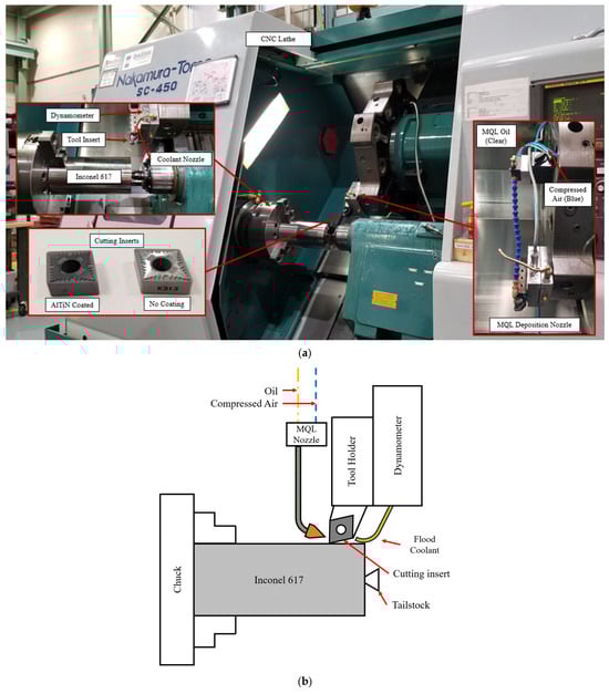
Figure 1.
(a) The Nakamura-Tome SC-450 CNC lathe with equipment used in the turning tests. (b) A schematic showing the turning setup, including the tool and dynamometer and coolant deposition methods.
The tool holder is adapted with a nozzle to provide a flood coolant for the operation to cool the tool and workpiece while also flushing chips away from the contact point and cutting zone. The flood coolant was directed towards the rake face of the tool where chip formation occurs. For near-dry machining, an external MQL nozzle was adapted to the tool fixture to allow for oil mist deposition on the rake face of the tool where the point of highest temperatures occurred. This nozzle was connected to a compressed air line and provided compressed air at a constant 7 bar to aerosolize the MQL oil. Table 4 outlines the details of the coolant and oil used in the flood coolant and MQL tests.
Table 4.
Coolant deposition techniques used in this study.
A Kennametal (Kennametal Inc., Pittsburgh, PA, USA) K313 grade Kenloc™ tungsten carbide finishing insert (ISO catalogue number CNGG120408FS) was used in the turning tests as the substrate and uncoated tool, with coating depositions performed by commercial manufacturers, as listed in Table 5. The tool insert was held in an ISO catalogue number DCLNL124BK3 -5° tool holder.
Table 5.
Coatings deposited on Kennametal K313 grade Kenloc™ WC finishing inserts.
The experiment was conducted using three studies to evaluate different parameters in cutting that affect the surface condition of the Inconel 617 workpiece: tool coatings, cutting parameters, and coolant. Study A was conducted to measure the tool life of the uncoated and coated tools. Coatings were deposited either through physical vapour deposition (PVD) or chemical vapour deposition (CVD). The ISO 3685 standard for tool life testing in single-point turning tools was used to determine the cutting parameters of this test [41]. A low cutting speed of 40 m/min was used with a 0.125 mm/rev feed rate and 0.25 mm depth of cut. Cuts were performed in 50 mm passes over the workpiece until the tool reached 300 µm of flank wear, which is the failure criterion determined by the referenced ISO standard in Section 8.2.2b. Flood coolant was used in this tool life test. Five different tool coatings were tested for their effects on the tool life, as can be seen in Table 5.
Study B was conducted to investigate the influence of cutting parameters on the surface finish of the generated surface. The cutting speed, feed rate, and depth of cut were used as the controlled parameters with three values for each parameter. The cutting parameter ranges were selected to encompass a low, medium, and high value for each variable and were based on the literature of similar machinability studies performed on Inconel 718, such as the one performed by Pinheiro et al. [17].
Taguchi’s L9 orthogonal array was used as a design of experiment methodology to determine the cutting tests [42]. Tests were conducted by cutting 50 mm passes across the Inconel 617 workpiece, measuring the surface finish with a Mitutoyo SJ201 (Mitutoyo Canada Inc, Mississauga, ON, Canada) portable surface profilometer, and repeating until the tool reached the length corresponding to the initial break-in region of the tool life. These tests are performed with a flood coolant. The cutting parameters that generated the best average roughness were used to conduct the MQL experiments.
Study C was run to assess the effects of cutting parameters and coolant application to the work hardening characteristics of machining Inconel 617. Work hardening tests were performed on an Anton Paar NHT3 nano-indenter (Anton Paar Canada Inc., Montreal, ON, Canada) on cross-sectioned samples of the machined workpiece mounted in epoxy resin. Indentations were performed by loading a Berkovich BBF-24 tip until reaching 50 mN where it dwelled for 2 s before unloading. This process was performed five times across the depth of the sample, with 20 µm of spacing between the centres and 5 µm spacing between the sample edge and the first indentation. This provided a hardness profile of the workpiece across the depth. The surface texture was analyzed using an Alicona InfiniteFocus digital microscope (Bruker Alicona, Raaba, Austria). Images of the generated surface scanned at varying depths generate the topography of the surface. This was used to accurately measure and model the surface finish and analyze to detect surface defects.
4. Results and Discussion
4.1. Study A: Tool Coatings
The uncoated K313 tungsten carbide tool lasted a total distance of 5460 m cutting length before reaching the tool failure criterion of 300 µm flank wear as per ISO 3685 Section 8.2.2b. Rapid failure began to occur at 4850 m after a short period of steady-state tool wear. No initial break in region was identified for the uncoated tool. The final cutting lengths for the tested coatings and uncoated tool is summarized in Table 6. It can be observed that the majority of the tool coatings increased the life of the tool, while the Balzers Balinit®® Aldura and Ionbond coatings had significantly shorter lifespans than the uncoated tool. A possible explanation for this phenomenon is that these two coatings are multi-layered, which increases the susceptibility to delamination between coating layers and cracking that promotes the rapid fracture of these tools [43,44]. This delamination and failure of multilayered coatings was also seen in the machining of Inconel 718, suggesting a commonality between the sister alloys and machining with multilayered coatings [27,45].
Table 6.
Tool lives of the tested tool coatings and the uncoated tool.
The tool coating that provided the longest tool life is the AlTiN coating provided by Balzers, also known as the Balzers Baliq®® Altinos coating. This tool coating increased the tool life to a cutting distance of 10,923.00 m, as shown in Figure 2. The rapid failure of this coated tool occurred at 10,350 m of cutting. The steady-state region of tool wear began for the majority of the coatings around the 2000 m cutting distance, after the initial break in region, if they did not exhibit rapid tool failure.
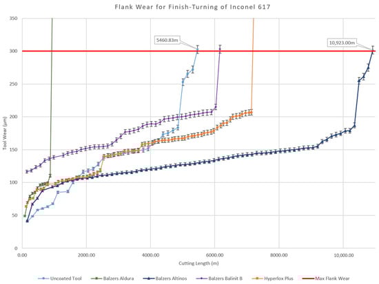
Figure 2.
Tool life tests for turning of Inconel 617 with uncoated tool and all tested tool coatings. Ionbond coating is not shown due to rapid failure of coating.
The tool lives for the uncoated tool and the tested tool coatings are depicted in Figure 2, which shows the flank wear measured for the duration of its entire tool life until it reaches 300 µm. From the experiment, the AlTiN PVD-coated tool can be seen to nearly double the lifespan of the cutting tool, as well as generating a very gradual increase in tool wear in the steady-state region of the tool. The rate of flank wear in this steady-state region was measured to be 6.72 µm/km of cutting. This is a 75.89% improvement from the uncoated tool’s rate of flank wear of 27.87 µm/km of cutting. The observed improvement in tool life using a monolayer coating is much greater than those presented in similar machining studies performed on Inconel 718, where the tool life was only increased by 40% at high speeds [46] or at similar speeds, which tended to reduce the tool’s life [27]. This suggests that monolayer coatings are most effective in machining Inconel 617. The results indicate that the presence of a hard protective coating is effective in reducing the abrasion caused by the hard workpiece due to the slow progression of flank wear. Of the tested coatings, the AlTiN coating by Balzers provided the longest tool life. It was from this test that the PVD AlTiN coating was chosen to conduct further experiments.
4.2. Study B: Influence of Cutting Parameters
The tests performed using the cutting parameters in Table 7 were cooled using flood coolant and machined to a total cutting length of 2000 m. This was the distance identified in the first tool coating tests and the initial break in region of the tool with the AlTiN coating in Figure 2. The average surface roughness was measured at the final pass for each cutting parameter and final tool flank wear was recorded. Cutting tests that reached tool failure before the 2000 m initial break-in region do not have a recorded final flank wear and their tool failure mechanism is recorded.
Table 7.
Taguchi L9 orthogonal array for cutting tests.
Tests T1, T4, and T7 exhibited the lowest average surface roughness and final flank wear. These tests also correspond with the lowest feed rate tested in the array, 0.075 mm/rev. This aligns with the main effect plot for the mean of means for average roughness Ra (Figure 3); this shows that the feed rate has the highest impact on the surface roughness, especially as the feed rate increases. A large depth of cut has an increased mean influence on the average roughness, whereas cutting speed displays an inverse effect, with low cutting speeds generating increased roughness. The impact of these cutting parameters on the surface roughness in turning Inconel 617 exhibited similar results to tests performed on Inconel 718, where the feed rate has the largest impact on surface roughness. Additionally, decreasing the feed rate and depth of cut while increasing cutting speed can improve the surface finish [47]. To further assess methods of improving surface quality, tests T1, T4, and T7 are used in the coolant deposition tests.
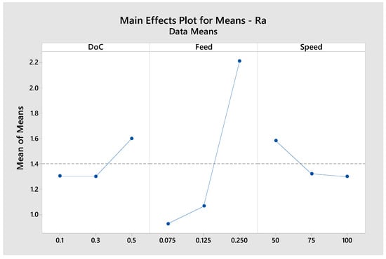
Figure 3.
Main effect plot for depth of cut, feed rate, and cutting speed on mean of means for average roughness.
4.3. Study C: MQL vs. Conventional Coolant
In Study C, the cutting force data were collected to analyze the resultant cutting forces in MQL compared to its flood coolant counterpart to detect if the cutting forces had an impact on the surface quality. Upon analyzing the data as shown in Figure 4, it was observed that the forces acting in both the MQL and flood coolant are of a similar magnitude, having a maximum percentage difference of 5.77%, which occurred in the feed direction of the T7 tests. These results suggest that the cutting forces caused by varying the coolant method have little relation to the surface quality of each test and did not impact the following three sub-studies.
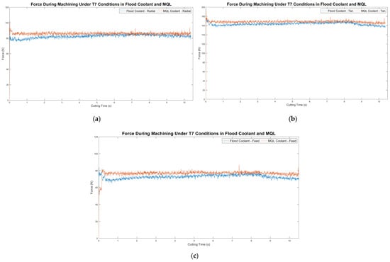
Figure 4.
Cutting forces observed in the machining of Inconel 617 under T7 conditions (DoC = 0.5 mm, feed = 0.075 mm/rev, cutting speed = 75 m/min). The plots compare MQL and the flood coolant for (a) radial force, (b) tangential force and (c) feed force.
4.3.1. Surface Roughness
Figure 5 illustrates the measured roughness for the generated surfaces in T1, T4, and T7 cutting conditions, comparing the coolant deposition methods. It can be observed that across all tests, MQL generated a lower average surface roughness compared to the flood coolant regardless of the cutting parameters used. The use of MQL in this process yielded up to a 47% improvement in the average roughness of the machined Inconel 617 workpiece. This aligns with studies performed on Inconel 718 where MQL greatly reduced the surface roughness of the machined surface in comparison to the flood coolant or dry conditions [9,22].
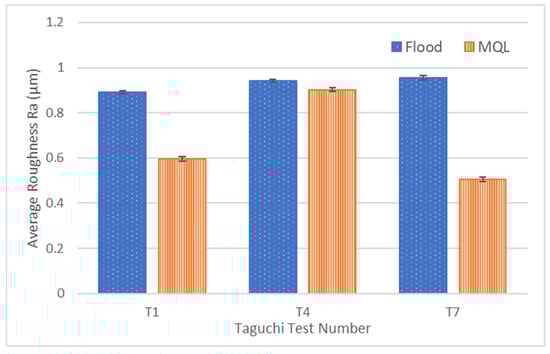
Figure 5.
Average surface roughness measurements of three cutting conditions under flood coolant and MQL.
To better visualize the effect of the coolant on the generated surface, a surface topography map was generated for T7, which had the largest disparity between its average roughness, shown in Figure 6. It can be seen in the images that machining in the flood coolant creates a uniform peak-and-valley lay pattern, whereas the surface machined with MQL has a much more irregular but smoother finish with lower average roughness.
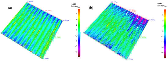
Figure 6.
Surface topography maps of the machined surface using T7 parameters and (a) the flood coolant and (b) MQL.
4.3.2. Tool Wear
All tools used in this study had similar methods of tool wear, namely large flank wear and a presence of crater wear. Measurements of the final flank wear indicate that MQL generates larger flank wear in each instance of the cutting tests in comparison to the flood coolant, with Test 7 having the largest increase in flank wear of 14.0%, as shown in Table 8. This increased tool wear is similar to the MQL effects on the machining of Inconel 718, where tool life is decreased using MQL compared to the flood coolant [48]. The larger tool wear may be attributed to the oil deposition location during cutting. The MQL deposition nozzle is directed towards the rake face of the tool to promote chip sliding; however, it does not provide any lubrication to the flank face.
Table 8.
Final flank wear for the three cutting conditions using both coolant conditions.
The presence of crater wear on the rake face indicates elevated temperatures occurring in the cut. Due to the high temperatures and abrasive particles, the rake face of the tool was quickly delaminated of its coating in the cutting zone as shown in Figure 7. This caused the Inconel 617 workpiece to weld and adhere itself to the tool substrate, creating a built-up edge along the cutting edge. At higher intensity cuts, such as those performed in tests T6, T8, and T9, the built-up edge led to rapid tool failure and breakage.
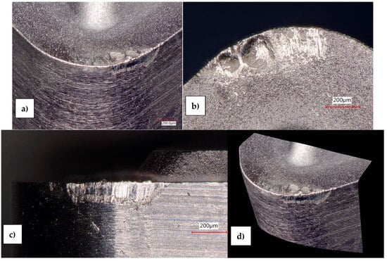
Figure 7.
Microscope images of the turning tool edge for T1 (DoC = 0.1 mm, feed = 0.075 mm/rev, cutting speed = 50 m/min) showing (a) a nose image of the full cutting edge (b) the crater wear on the rake face (c) the flank wear on the flank face and (d) a 3D angle showing the full tool wear.
4.3.3. Material Characterization—Work Hardening
The work hardening recovery in this paper is characterized by the hardness difference from the point of highest work hardening to the lowest, across the measured depth from the immediate subsurface in the white layer and through the plastic deformation zone, as shown in Figure 8. A sample of the as-received Inconel 617 was measured to have an average hardness of 340 ± 40 HV, known as the bulk hardness of the material. All conditions generated similar profiles of work hardening and recovery. The highest level of work hardening occurs just below the machined surface where machining temperatures and pressures are the highest and occurred in the range of 410–550 HV, as seen in Figure 9, before returning to the bulk hardness further into the subsurface.
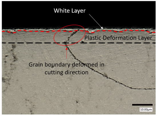
Figure 8.
A polished and etched sample of the cross-section of the machined Inconel 617 under T7 conditions (DoC = 0.5 mm, feed = 0.075 mm/rev, cutting speed = 75 m/min) showing the grain boundary deformation and presence of a white layer caused by machining.
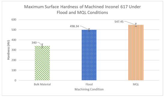
Figure 9.
The bulk and subsurface hardness of the machined Inconel 617 using flood and MQL coolants under T4 conditions (DoC = 0.3 mm, feed = 0.075 mm/rev, cutting speed = 100 m/min).
The coolant deposition method and the level of tool wear were found to have the largest influence on the level of work hardening recovery, whereas the cutting parameters used had a minor impact in comparison (Figure 10 and Figure 11, through the Taguchi design of the experiments). The main effect plot shows that MQL has a higher mean strength than the flood coolant in the experiments. New tools showed a higher mean strength than the worn tools. However, the impact of the method of coolant deposition on the work hardening is also influenced by the cutting parameters used as shown in the interaction between these factors. Additionally, the interaction plot in Figure 11 shows that the parameters have an impact on each others’ relationship to the work hardening recovery with the exception of coolant use and tool wear, which are independent of each other.
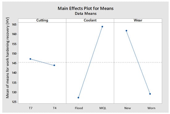
Figure 10.
Main effect plot for work hardening recovery.
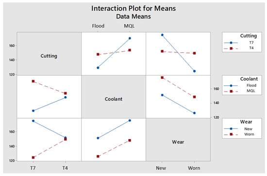
Figure 11.
Interaction plot for work hardening recovery.
It was observed that in every case, MQL generated a greater level of work hardening in the immediate subsurface, with HV values between 495 and 550 HV, while the flood coolant generated HV values between 410 and 500 HV. Due to the location of MQL mist deposition, directed towards the rake face of the tool and generated chip, the flank face had limited cooling and resulted in higher friction and pressure between the tool and the generated surface, causing the high level of initial work hardening. However, in studies performed on MQL machining of other Inconel grades, MQL generated lower initial hardnesses compared to flood cooling [21,49]. This phenomenon may be caused by the MQL deposition location directing the oil towards the flank face, as explained in their methodology.
5. Conclusions and Future Directions
5.1. Conclusions
In this paper, the influence of the tool coatings, feed rate, cutting speed, depth of cut, and MQL deposition on the surface integrity of turned Inconel 617 was observed. The purpose of this research was to address the gap in the existing literature about the lack of research in machining Inconel 617, studying the effectiveness of MQL in machining Inconel 617 for nuclear applications, as well as the impact that machining may have on the subsurface material to better measure the machined surface quality. The following are the conclusions reached through the studies conducted in this paper:
- The addition of an AlTiN tool coating deposited on a K313 tungsten carbide tool insert increased the tool life in turning Inconel 617 from a 5460 m cutting distance to 10,350 m, doubling the tool life, and improving the rate of flank wear by 75.89%. This large improvement in tool life creates a more efficient manufacturing line by minimizing downtime caused by tool failure and reducing costs associated with labour in tool changes and scrapped components.
- It was found that MQL generated a better surface finish in comparison to the conventional flood coolant in all cases of varying cutting parameters, with a maximum improvement of 47%. In the flood coolant, the variation in cutting parameters had a minimal effect on the surface finish, whereas varying the cutting parameters in MQL cooling generated large differences in the surface finish.
- Observing the influence of tool wear, it was found that MQL deposition generated a larger amount of flank wear compared to those turned using flood coolant. A cause of this difference in wear was identified as the location of oil deposition in MQL. Due to the single nozzle depositing oil on the rake face, the flank face may not have been sufficiently lubricated and cooled, leading to increased flank wear.
- Measurements of work hardening in this study revealed that MQL generated larger levels of work hardening compared to the flood coolant in all cases. MQL turning generated hardness levels between 495 and 550 HV, whereas the coolant in turning generated values between 410 and 500 HV. The mean of means revealed that the coolant used had the largest impact on the level of work hardening, with tool wear closely second.
- From the existing literature that studied the machining of Inconel 718 and similar alloys, the machining of Inconel 617 was able to be compared and understood further.
- Multi-layered coatings have the tendency to delaminate and cause tool failure in machining Inconel alloys. Monolayer coatings greatly improved tool life in machining Inconel 617 in comparison to Inconel 718.
- The impact of cutting parameters on the surface roughness of Inconel 617 is similar to that of Inconel 718, suggesting that the influence of cutting parameters is consistent across various Inconel grades.
- MQL deposition reduces the surface roughness while increasing the level of tool wear in both grades of Inconel; however, the surface hardness of Inconel 617 was much larger under the MQL conditions compared to other grades where the surface hardness was reduced.
5.2. Future Work
Although this paper was able to address the gaps found in the literature on the machining of Inconel 617, there were still many limitations in the experiments that could be used to enhance future studies in this field. From the results of this paper, these are the experimental directions that are recommended for future studies:
- When conducting MQL trials, it is recommended to include more than one deposition nozzle to lubricate the entire cutting surface as much as possible. This would include at least one nozzle for each cutting face on the tool—the rake face and the flank face—where the points of highest temperature occur. This would allow a better analysis on the total effects of MQL on tool wear.
- Study the effects of varying the air pressure delivered to the nozzles. This was not possible with the available MQL equipment as it only provided a constant air pressure. Studying the variation in air pressure may give a better understanding of the full breadth of the impact of MQL in machining Inconel 617.
- Test the effectiveness of advanced coatings in machining Inconel 617. Self-lubricating or ultra-soft coatings may be considered as candidates to improve the machinability of this material and has yet been tested extensively.
- Residual stress analysis performed through X-ray diffraction (XRD) can give a better understanding of how the Inconel 617 subsurface is affected by the machining process and provide insights as to how the machined components could perform under intense environments such as those in a nuclear reactor.
- Perform an in-depth assessment of the cutting parameters’ interactions with MQL and flood coolant deposition to determine the impact the interactions between the cutting parameters and coolant deposition techniques have on the surface finish of machined Inconel 617.
- Study the influence of the surface deformation layer on the corrosion and oxidation resistance properties, as well as chemical composition of Inconel 617. While the high resistance properties of this alloy are largely known, it is insightful to understand how the manufacturing of this metal generates a deformation layer and how it will impact its properties in nuclear applications.
- Chip morphology analysis can provide further insight into the impact of MQL and flood coolants on the quality of the machined surface and its influence on tool wear. It is recommended to perform chip analyses to determine the cutting modes in machining Inconel 617.
Author Contributions
Conceptualization, R.L.; methodology, R.L.; formal analysis, R.L.; investigation, R.L.; data curation, R.L.; writing—original draft preparation, R.L.; writing—review and editing, R.L., J.M.D. and A.H.C.; visualization, J.M.D. and A.H.C.; supervision, S.C.V.; project administration, S.C.V.; funding acquisition, S.C.V. All authors have read and agreed to the published version of the manuscript.
Funding
This research was supported by the Natural Sciences and Engineering Research Council of Canada (NSERC) under their Discovery Research Grant Program RGPIN-2019-07096.
Institutional Review Board Statement
Not applicable.
Informed Consent Statement
Not applicable.
Data Availability Statement
The original contributions presented in this study are included in the article. Further inquiries can be directed to the corresponding author.
Conflicts of Interest
The authors declare that they have no financial interest or personal relationships that can inappropriately bias this work.
Abbreviations
The following abbreviations are used in this manuscript:
| ASME | American Society of Mechanical Engineers |
| BPVC | Boiler and Pressure Vessel Code |
| BUE | Built-up edge |
| LPBF | Laser Powder Bed Fusion |
| MAF | Magnetic Field-Assisted Finishing |
| MQL | Minimum Quantity Lubrication |
| MRR | Material removal rate |
| MSR | Molten Salt Reactor |
| SMR | Small Modular Reactor |
| VHTR | Very-High-Temperature Reactor |
| XRD | X-ray diffraction |
References
- WNA. Nuclear Power in Canada—World Nuclear Association. 2018. Available online: https://world-nuclear.org/information-library/country-profiles/countries-a-f/canada-nuclear-power.aspx (accessed on 23 April 2025).
- CER. Market Snapshot: Canada’s Nuclear Energy Output Ranked 6th in the World. 2023. Available online: https://www.cer-rec.gc.ca/en/data-analysis/energy-markets/market-snapshots/2017/market-snapshot-canadas-nuclear-energy-output-ranked-6th-in-world.html (accessed on 23 April 2025).
- A Call to Action: A Canadian Roadmap for Small Modular Reactors. 2018. Available online: https://smrroadmap.ca/wp-content/uploads/2018/11/SMRroadmap_EN_nov6_Web-1.pdf (accessed on 2 August 2022).
- Inconel-617—Heanjia Super Metals, Co. Ltd. Available online: https://super-metals.com/wp-content/uploads/2015/03/Inconel-617.pdf (accessed on 29 September 2021).
- ASME Boiler and Pressure Vessel Code 2019. New York, NY, 2019. Available online: https://www.ipgmservicios.com/wp-content/uploads/2024/03/ASME-BPVC.IV_.2019-Rules-for-Construction-of-Heating-Boilers.pdf (accessed on 25 August 2023).
- Murty, K.L.; Charit, I. Structural materials for Gen-IV nuclear reactors: Challenges and opportunities. J. Nucl. Mater. 2008, 383, 189–195. [Google Scholar] [CrossRef]
- Ren, W.; Swindeman, R. A review on current status of alloys 617 and 230 for gen IV nuclear reactor internals and heat exchangers. J. Press. Vessel. Technol. Trans. ASME 2009, 131, 044002. [Google Scholar] [CrossRef]
- Ren, X.; Liu, Z. Influence of cutting parameters on work hardening behavior of surface layer during turning superalloy Inconel 718. Int. J. Adv. Manuf. Technol. 2016, 86, 2319–2327. [Google Scholar] [CrossRef]
- Kamata, Y.; Obikawa, T. High speed MQL finish-turning of Inconel 718 with different coated tools. J. Mater. Process Technol. 2007, 192, 281–286. [Google Scholar] [CrossRef]
- Obikawa, T.; Kamata, Y.; Shinozuka, J. High-speed grooving with applying MQL. Int. J. Mach. Tools Manuf. 2006, 46, 1854–1861. [Google Scholar] [CrossRef]
- Venkatesan, K.; Mathew, A.T.; Devendiran, S.; Ghazaly, N.M.; Sanjith, S.; Raghul, R. Machinability study and multi-response optimization of cutting force, Surface roughness and tool wear on CNC turned Inconel 617 superalloy using Al2O3 Nanofluids in Coconut oil. In Procedia Manufacturing; Elsevier B.V.: Amsterdam, The Netherlands, 2019; pp. 396–403. [Google Scholar] [CrossRef]
- Sathish, V.; Arul, T.; Subbiah, K.; Ravichandran, R.; Mohanavel, M. Optimization on end milling operating parameters for super alloy of Inconel 617 by Taguchi’s L27 orthogonal array. J. Phys. Conf. Ser. 2021, 2027, 012013. [Google Scholar] [CrossRef]
- Montazeri, S.; Aramesh, M.; Veldhuis, S.C. Novel application of ultra-soft and lubricious materials for cutting tool protection and enhancement of machining induced surface integrity of Inconel 718. J. Manuf. Process 2020, 57, 431–443. [Google Scholar] [CrossRef]
- Montazeri, S.; Aramesh, M.; Rawal, S.; Veldhuis, S.C. Characterization and machining performance of a chipping resistant ultra-soft coating used for the machining of Inconel 718. Wear 2021, 474–475, 203759. [Google Scholar] [CrossRef]
- Upadhyay, C.; Rajput, S.S.; Kumar, C.S.; Gangopadhyay, S.; Sahoo, S.K. Performance evaluation of WC, SiAlON and SiCw + Al2O3 tools in dry machining of Inconel 617. J. Manuf. Process 2024, 109, 235–249. [Google Scholar] [CrossRef]
- Tandekar, N.; Kumar, A.; Valleti, K. Machining of Ni-based superalloys using CAPVD coated carbide tools. Mater. Today Commun. 2024, 39, 109101. [Google Scholar] [CrossRef]
- Pinheiro, C.; Kondo, M.Y.; Amaral, S.S.; Callisaya, E.S.; De Souza, J.V.C.; De Sampaio Alves, M.C.; Ribeiro, M.V. Effect of machining parameters on turning process of Inconel 718. Mater. Manuf. Process. 2021, 36, 1421–1437. [Google Scholar] [CrossRef]
- Bushlya, V.; Zhou, J.M.; Lenrick, F.; Avdovic, P.; Ståhlan, J.E. Characterization of white layer generated when turning aged inconel 718. Procedia Eng. 2011, 19, 60–66. [Google Scholar] [CrossRef]
- Buddaraju, K.M.; Sastry, G.R.K.; Kosaraju, S. A review on turning of Inconel alloys. In Materials Today: Proceedings; Elsevier Ltd.: Amsterdam, The Netherlands, 2021; pp. 2645–2652. [Google Scholar] [CrossRef]
- Zhao, B.; Hutt, K.; Yamaguchi, H.; Pan, S. Surface corrosion in laser powder bed fusion-fabricated Inconel 718 with magnetic field-assisted post-processing. J. Manuf. Process 2025, 143, 277–292. [Google Scholar] [CrossRef]
- Xavior, M.A.; Manohar, M.; Madhukar, P.M.; Jeyapandiarajan, P. Experimental investigation of work hardening, residual stress and microstructure during machining Inconel 718. J. Mech. Sci. Technol. 2017, 31, 4789–4794. [Google Scholar] [CrossRef]
- Yazid, M.Z.A.; Ibrahim, G.A.; Said, A.Y.M.; CheHaron, C.H.; Ghani, J.A. Surface integrity of Inconel 718 when finish turning with PVD coated carbide tool under MQL. Procedia Eng. 2011, 19, 396–401. [Google Scholar] [CrossRef]
- Sharman, A.R.C.; Hughes, J.I.; Ridgway, K. Workpiece surface integrity and tool life issues when turning inconel 718TM nickel based superalloy. Mach. Sci. Technol. 2004, 8, 399–414. [Google Scholar] [CrossRef]
- Fox-Rabinovich, G.S.; Yamamoto, K.; Aguirre, M.H.; Cahill, D.G.; Veldhuis, S.C.; Biksa, A.; Dosbaeva, G.; Shuster, L.S. Multi-functional nano-multilayered AlTiN/Cu PVD coating for machining of Inconel 718 superalloy. Surf. Coat. Technol. 2010, 204, 2465–2471. [Google Scholar] [CrossRef]
- Montazeri, S.; Aramesh, M.; Arif, A.F.M.; Veldhuis, S.C. Tribological behavior of differently deposited Al-Si layerin the improvement of Inconel 718 machinability. Int. J. Adv. Manuf. Technol. 2019, 105, 1245–1258. [Google Scholar] [CrossRef]
- Cantero, J.L.; Díaz-Álvarez, J.; Miguélez, M.H.; Marín, N.C. Analysis of tool wear patterns in finishing turning of Inconel 718. Wear 2013, 297, 885–894. [Google Scholar] [CrossRef]
- Bhatt, A.; Attia, H.; Vargas, R.; Thomson, V. Wear mechanisms of WC coated and uncoated tools in finish turning of Inconel 718. Tribol. Int. 2010, 43, 1113–1121. [Google Scholar] [CrossRef]
- Liang, X.; Liu, Z. Tool wear behaviors and corresponding machined surface topography during high-speed machining of Ti-6Al-4V with fine grain tools. Tribol. Int. 2018, 121, 321–332. [Google Scholar] [CrossRef]
- Singh, R. Minimum quantity lubrication turning of hard to cut materials—A review. Mater. Today Proc. 2020, 37, 3601–3605. [Google Scholar] [CrossRef]
- Kaynak, Y. Evaluation of machining performance in cryogenic machining of Inconel 718 and comparison with dry and MQL machining. Int. J. Adv. Manuf. Technol. 2014, 72, 919–933. [Google Scholar] [CrossRef]
- ASTM B-166-11; Standard Specification for Nickel-Chromium-Iron Alloys (UNS N06600, N06601, N06603, N06690, N06693, N06025, N06045, and N06696), Nickel-Chromium-Cobalt-Molybdenum Alloy (UNS N06617), and Nickel-Iron-Chromium-Tungsten Alloy (UNS N06674) Rod, Bar. American National Standards Institute (ANSI): Washington, DC, USA, 2011.
- ASME BPVC.II.B-2017 SB 166; ASME Boiler and Pressure Vessel Code, Section II Part B—Nonferrous Material Specifications. American Society of Mechanical Engineers (ASME): New York, NY, USA, 2017.
- ASTM E1019-18; Standard Test Methods for Determination of Carbon, Sulfur, Nitrogen, and Oxygen in Steel, Iron, Nickel, and Cobalt Alloys by Various Combustion and Inert Gas Fusion Techniques. American National Standards Institute (ANSI): Washington, DC, USA, 2018.
- ASTM E1086-14; Standard Test Method for Analysis of Austenitic Stainless Steel by Spark Atomic Emission Spectrometry. American National Standards Institute (ANSI): Washington, DC, USA, 2014.
- ASTM E3047-16; Standard Test Method for Analysis of Nickel Alloys by Spark Atomic Emission Spectrometry. American National Standards Institute (ANSI): Washington, DC, USA, 2016.
- ASTM E572-13; Standard Test Method for Analysis of Stainless and Alloy Steels by Wavelength Dispersive X-Ray Fluorescence Spectrometry. American National Standards Institute (ANSI): Washington, DC, USA, 2013.
- ASTM E1085-16; Standard Test Method for Analysis of Low-Alloy Steels by Wavelength Dispersive X-Ray Fluorescence Spectrometry. American National Standards Institute (ANSI): Washington, DC, USA, 2016.
- ASTM E1621-13; Standard Guide for Elemental Analysis by Wavelength Dispersive X-Ray Fluorescence Spectrometry. American National Standards Institute (ANSI): Washington, DC, USA, 2013.
- ASTM E2465-19; Standard Test Method for Analysis of Ni-Base Alloys by Wavelength Dispersive X-Ray Fluorescence Spectrometry. American National Standards Institute (ANSI): Washington, DC, USA, 2019.
- SAE AMS 5887 D; Nickel Alloy, Corrosion and Heat-Resistant, Bars, Forgings, and Rings 54Ni - 22Cr - 12.5Co - 9.0Mo - 1.2Al Consumable Electrode or Vacuum Induction Melted Annealed. SAE International: Warrendale, PA, USA, 2015.
- ISO 3685:1993; Tool-life testing with single-point turning tools. ISO: Geneva, Switzerland, 1993.
- Fraley, S.; Zalewski, J.; Oom, M.; Terrien, B. 14.1: Design of experiments via taguchi methods—Orthogonal arrays. pp. 1–10. Available online: https://eng.libretexts.org/@go/page/22674 (accessed on 17 April 2025).
- Vereschaka, A.A.; Grigoriev, S.N.; Sitnikov, N.N.; Batako, A.D. Delamination and longitudinal cracking in multi-layered composite nano-structured coatings and their influence on cutting tool life. Wear 2017, 390, 209–219. [Google Scholar] [CrossRef]
- Vereschaka, A.A.; Grigoriev, S.N. Study of cracking mechanisms in multi-layered composite nano-structured coatings. Wear 2017, 378, 43–57. [Google Scholar] [CrossRef]
- Boyle, H.; Norgren, S.; Crawforth, P.; Christofidou, K.; Boing, D. Insights in α-Al2O3 degradation in multilayer CVD coated carbide tools. Wear 2023, 523, 204786. [Google Scholar] [CrossRef]
- Soo, S.L.; Khan, S.A.; Aspinwall, D.K.; Harden, P.; Mantle, A.L.; Kappmeyer, G.; Pearson, D.; M’Saoubi, R. High speed turning of Inconel 718 using PVD-coated PCBN tools. CIRP Ann. Manuf. Technol. 2016, 65, 89–92. [Google Scholar] [CrossRef]
- Jafarian, F.; Umbrello, D.; Golpayegani, S.; Darake, Z. Experimental Investigation to Optimize Tool Life and Surface Roughness in Inconel 718 Machining. Mater. Manuf. Process. 2016, 31, 1683–1691. [Google Scholar] [CrossRef]
- Pereira, O.; Celaya, A.; Urbikaín, G.; Rodríguez, A.; Fernández-Valdivielso, A.; de Lacalle, L.N.L. CO2 cryogenic milling of Inconel 718: Cutting forces and tool wear. J. Mater. Res. Technol. 2020, 9, 8459–8468. [Google Scholar] [CrossRef]
- Singh, R.; Sharma, V. Machining induced surface integrity behavior of nickel-based superalloy: Effect of lubricating environments. J. Mater. Process Technol. 2022, 307, 117701. [Google Scholar] [CrossRef]
Disclaimer/Publisher’s Note: The statements, opinions and data contained in all publications are solely those of the individual author(s) and contributor(s) and not of MDPI and/or the editor(s). MDPI and/or the editor(s) disclaim responsibility for any injury to people or property resulting from any ideas, methods, instructions or products referred to in the content. |
© 2025 by the authors. Licensee MDPI, Basel, Switzerland. This article is an open access article distributed under the terms and conditions of the Creative Commons Attribution (CC BY) license (https://creativecommons.org/licenses/by/4.0/).