Abstract
The RV-40E reducer is the representative model of the a typical RV reducer, where transmission accuracy and manufacturing cost are two important optimization indicators, while transmission accuracy depends on both the selection of accuracy levels for components, such as bearings, and the design of tolerance values for parts such as cycloidal gears. The selection of accuracy levels, such as bearings, is relatively simple, and studying manufacturing costs requires the use of a large amount of data from manufacturing equipment and processing methods. Therefore, this article mainly studies the design optimization problem of tolerance values closely related to transmission accuracy. The RV-40E reducer is designed based on the experience of engineers. So far, it is unclear whether the tolerance value design of parts such as cycloidal gears meets the optimization requirements of transmission accuracy. This article first explains the research background and the necessity of tolerance value design for RV-40E components. Next, it details the reducer’s structural composition and lists specific part tolerance values. Subsequently, a virtual prototype is established to evaluate transmission errors under different component and part combinations. Finally, through the design of experiment analysis, optimal tolerance values are derived for selected parts as recommended in the final table. The results demonstrate that the optimized tolerance values for RV-40E reducers are basically consistent with the empirical tolerance values designed by engineers, achieving similar results.
1. Introduction
The tolerance, characterized by two parameters, bandwidth and position, is defined as a range of allowable changes in work piece size, geometric shape, or relative position. It is the physical quantity that limits the processing error of work pieces, reflects the requirements for manufacturing accuracy, and reflects the machining difficulty. The RV reducer is the critical component of industrial robots. The transmission error, defined as the difference between the actual output angle and the theoretical angle at the same input angle [1], directly affects the performance and work efficiency of industrial robots. As a standard medium-sized reducer in the basic series, the RV-40E covers the most prevalent load range for industrial robot applications, with its dimensional and performance characteristics being representative of this reducer class. Currently, the accuracy requirements or tolerance design of various components of the RV-40E reducer mainly rely on the experience of engineers, so some tolerance values are suboptimal. Therefore, in order to reduce the transmission error of the RV-40E reducer and lower its production cost, it is necessary to conduct research on the accuracy selection or tolerance values of various components of the RV-40E reducer.
The transmission error of RV reducers has garnered significant research attention in recent years. Li et al. explored the impact of tooth profile modification and clearance on the transmission error using a contact analysis model for cycloid pin teeth [2]. Yang developed an equivalent model for the transmission error by considering the over-constraint effects in the multi-crankshaft mechanism and verified its accuracy through experiments [3]. Through mathematical modeling and experimental verification, Ran et al. identified the primary error sources in key parts and their impact mechanisms on transmission accuracy [4]. Wei Zheng et al. incorporated manufacturing and assembly errors alongside elasticity factors to propose an analytical method for the dynamic transmission error [5]. Xu et al. investigated the error characteristics under loaded conditions using a multi-body dynamics approach [6]. Wang et al., on the other hand, conducted a comprehensive analysis of the transmission error by formulating a mathematical model of the RV reducer and integrating it with a translation–torsion coupling model [7].
Meanwhile, virtual prototype technology has found widespread applications in transmission error analysis. Li et al. utilized ADAMS software to construct a virtual prototype of the RV reducer and analyzed the system’s natural frequency and dynamic characteristics through finite element analysis [8]. Zhang et al. developed a virtual prototype of the RV reducer based on multi-body dynamics theory with ADAMS software, incorporating the planetary gear system and the backlash model between the eccentric shaft and the bearing [9]. Additionally, they investigated the variation in transmission error as a function of clearance. Jiang et al. integrated virtual prototype simulation, physical testing, and theoretical modeling to conduct a systematic analysis of the dynamic transmission performance of the RV reducer [10]. They employed a multi-fidelity model and Bayesian updating techniques to assess system reliability and quantify the impact of manufacturing and assembly errors on a transmission accuracy sensitivity analysis of transmission error-related parameters using a virtual prototype simulation [11]. Li Hui employed virtual prototype technology in conjunction with the orthogonal experiment method to investigate the combined error effects of the cycloid wheel and pin wheel on the transmission error [12]. Xi Ying et al. applied virtual prototype technology in conjunction with rigid–flexible coupling modeling to investigate the dynamic performance and error sources of the RV reducer [13,14]. Wang et al. [15] analyzed the effects of multifactor error interactions on the transmission accuracy of the RV reducer by employing virtual prototype technology and the response surface methodology (RSM). Xu et al. [16] revealed the significant influences of angular acceleration and load inertia on the transmission errors under variable-speed conditions by constructing a multi-body dynamics model of the RV reducer that considers typical part geometrical errors. Gao et al. [17] proposed a piecewise modification method for cycloidal gears based on the spline interpolation theory and verified its advantages over combined modifications in terms of contact stress and load distribution through a virtual prototype. Liu et al. [18] used ADAMS to establish a coaxiality–efficiency model of the RV reducer, which revealed the influence of coaxiality errors on efficiency. Han et al. [19] used an Abaqus–ADAMS rigid–flexible coupling model to investigate the contact stress characteristics of the key components of the RV reducer. Wang et al. [20] verified the dynamic characteristics of the novel ZHPRER reducer through multi-body dynamics simulations and experimental validations. Based on the multi-tooth contact and transmission error model, Wang et al. [21] verified the influence of tooth profile modification and load and proposed a reverse modification method applicable under large clearance and large torque conditions. Tao et al. [22] revealed the degradation relationship between cycloidal gear wear and the transmission error by employing a rigid–flexible coupling model and the Archard wear theory. Compared with traditional modeling methods, virtual prototype technology enables a more intuitive simulation of dynamic behavior under complex working conditions, reducing the reliance on complex assumptions and computational efforts associated with conventional mathematical modeling.
Parallel to these developments, tolerance design and optimization have received growing attention. Wu et al. analyzed the transmission error of the RV reducer considering the effects of manufacturing and assembly tolerances, employing gear theory, tooth contact analysis, and the Monte Carlo method [23]. Daijia Cao examined the influence of critical part tolerances on transmission accuracy and proposed an optimization design method [24]. Ahn, H. J. et al. conducted an in-depth study based on the finite element method to investigate the mechanism by which tolerance and friction affect the contact force and transmission performance in the RV reducer [25]. Chen et al. incorporated the design constraints of gear pair clearance and allowable backlash to construct a multi-objective optimization model that balances processing cost, quality loss, and tolerance cost for the cycloid pinion gear pair in the RV reducer [26]. Xie et al. analyzed the geometric distribution characteristics of assembly errors using 3DCS software [27]. Subsequently, the team further introduced a genetic algorithm to optimize the tolerances of the key components of the RV reducer, thereby minimizing the manufacturing costs while ensuring assembly accuracy [28]. Wang et al. evaluated the effects of varying tolerances on transmission accuracy using the Monte Carlo simulation [29]. Linh Tran [30] revealed that the momentum loss of the cycloidal reducer is jointly influenced by torsional stiffness and tolerances through combined finite element and kinematic analyses, thereby clarifying the key role of tolerances in determining accuracy. Li et al. [31] optimized the tolerance and modification parameters of the RV reducer based on a gear contact analysis model that considers tooth profile modifications and manufacturing errors, aiming to minimize costs while ensuring reliability. Wang et al. [32] quantified the effects of pin errors on momentum loss based on the BDTCA model, optimized the tolerance allocation using a discrete particle swarm optimization algorithm, and verified the validity of the bi-directional test. Zhang et al. [33] optimized the tolerance allocation using a state-space model to significantly reduce transmission errors and proposed a dynamic accuracy weighting strategy to balance cost and accuracy. Liu et al. [34] used a hybrid simulation PCE approach to evaluate various sensitivity indices and determine the optimal tolerance scheme for the transmission mechanism. Despite these valuable contributions, current research on the RV-40E reducer demonstrates two significant limitations regarding practical applications. Firstly, these studies fail to conduct a systematic assessment of how the tolerance design of individual components in the RV-40E reducer affects its transmission error. Secondly, they do not provide sufficient justification for the accuracy requirements or tolerance design of RV reducer components, nor do they establish a systematic approach for evaluating the appropriateness of tolerance design.
The above series of tolerance studies, although not related to the RV-40E reducer, can guide the selection of accuracy levels and the design of tolerance values for various components and parts of the RV-40E reducer. To improve the transmission accuracy and reduce the manufacturing costs, this article will deeply analyze the structural composition and tolerance value design of the RV-40E reducer. Specifically, we propose a method for selecting the accuracy level of externally purchased components, such as bearings. Based on the principle of multi-body dynamics, a virtual prototype of the RV-40E reducer will be established. The design of experiment (DOE) method is then adopted to analyze the reasonability of the tolerance values. Finally, the optimal scheme for the part tolerance values will be proposed to achieve the high-accuracy and low-cost manufacturing of the RV-40E reducer.
2. Materials and Methods
The research on the tolerances of various components of the RV-40E reducer involves the RV-40E reducer and its components, virtual prototype modeling software, and verification device. The method used is to establish a virtual prototype, calculate the transmission error of each component combination of the RV-40E reducer, analyze the factors affecting the quality of each component of the RV-40E reducer through experimental design techniques, and study the sensitivity of the transmission error at different tolerance value combinations. Then, tolerance value approximation or depth value research is conducted based on the different sensitivities of the factors to obtain the optimal selection of the accuracy level and the tolerance value design scheme for the RV-40E reducer components.
2.1. Structural Composition of the RV-40E Reducer
The RV-40E reducer serves as the primary transmission part in industrial robots. Its working principle is as follows: the motor shaft is connected to the input shaft, and power is transmitted to the output shaft through a series of parts, including an input shaft gear (1), two planetary gears (2), two crankshafts (3), four tapered roller bearings (10), four cylindrical roller bearings, two cycloid wheels (4), a pin wheel (8), pin-wheel housing (5), two angular contact ball bearings (11), the rigidly integrated input-end planet carrier (6), and the output-end planet carrier (7), as illustrated in Figure 1a. The RV-40E reducer employs a two-stage reduction system, consisting of a planetary gear reduction system at the input shaft end and a cycloid wheel reduction system within the pin-wheel housing. In this system, the crankshaft support (10) and the planet carrier support (11) on both sides are fixed. The output shaft is integrally connected to the planetary carrier, and the centerlines of the four tapered roller bearings rotate around the axes of the input and output shafts, while the centerlines of the four cylindrical roller bearings rotate around the centerlines of the tapered roller bearings. The physical structure of the RV-40E reducer is depicted in Figure 1b.
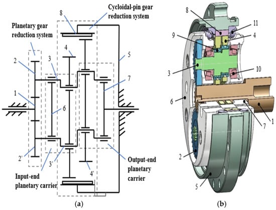
Figure 1.
Structural composition of the RV-40E reducer. (a) RV reducer working principle. (b) Structural composition of the RV reducer. 1. Input shaft; 2. planetary gear; 3. crankshaft; 4. cycloid wheel; 5. pin-wheel housing; 6. input-end planet carrier; 7. output-end planet carrier; 8. pin wheel; 9. cylindrical roller bearings; 10. tapered roller bearings; 11. angular contact ball bearing.
2.2. Accuracy of Components and Tolerance of Parts
The RV-40E reducer mentioned above includes four tapered roller bearings, four cylindrical needle roller bearings, two angular contact ball bearings, and some distance sleeves, gaskets, seals, etc. These externally purchased components, including distance sleeves, gaskets, collars, and sealing rings, have a minor impact on the transmission error and are therefore neglected in this study. Only four tapered roller bearings supporting the crankshaft, four cylindrical needle roller bearings supporting the cycloidal gear, and two angular contact ball bearings supporting the planetary carrier are related to the transmission error of the RV-40E reducer. Therefore, the selection of bearing accuracy levels depends on the existing bearing manufacturing technology level and the manufacturing cost requirements of the RV-40E reducer. However, if multi-objective optimization needs to be carried out by comprehensively considering transmission errors and manufacturing costs, factors affecting bearing accuracy levels can be added to the virtual prototype, and optimization results can be obtained by combining experimental design methods.
The RV-40E reducer is a representative RV reducer. The transmission accuracy and manufacturing cost of industrial robot RV-40E reducers are related to the selection of accuracy levels for components, such as bearings, and the design of tolerance values for parts such as cycloid gears. Bearings and other components can balance the transmission accuracy and manufacturing cost of the RV-40E reducer by selecting a grade that meets the requirements of accuracy or cost-effectiveness. According to the GB307 national standard, bearings have five accuracy grades: B, C, D, E, and G. Grade B is the highest accuracy bearing, while grade G is the lowest accuracy ordinary bearing. Except for a few RV reducers with particularly high accuracy requirements, such as the popular RV-40E reducer, due to cost limitations, its bearing accuracy levels are higher accuracy grades C and D, and ordinary accuracy grades E and G. The selection of accuracy levels for components, such as bearings, is relatively simple, while the design of tolerance values for parts such as cycloidal gears is difficult to meet the comprehensive requirements of transmission accuracy and manufacturing costs. Since the RV-40E reducer is designed based on the experience of engineers, currently, it is unknown whether the selection of accuracy levels for components, such as bearings, and the design of tolerance values for gears meet the requirements of transmission accuracy or cost-effectiveness. Transmission accuracy and manufacturing cost are two interrelated important indicators of the RV-40E reducer. Due to the fact that researching manufacturing costs will also involve a large amount of data on enterprise manufacturing processes and processing equipment, this article mainly studies the optimization problem of tolerance value design closely related to transmission accuracy.
In the design of the RV-40E reducer, the key characteristic tolerances are critical parameters for ensuring transmission accuracy, operational stability, and service life. Due to the extensive workload involved, this study focuses on investigating key characteristics closely related to transmission errors, including the hole center distance between the planet carrier and the cycloid wheel, the eccentric distance, the central circle of pin-wheel distribution, the pin-wheel diameter, and the cycloid wheel modification amount, among others. The determination of these tolerance parameters is primarily based on the production experience accumulated by the enterprise over many years, industry standards, and the recommended values provided in mechanical design manuals. Based on the RV-40E reducer drawings and technical requirements, medium and high accuracy bearings were selected according to the current domestic technical level, while the errors of individual bearings were not considered at this stage. The input gear and planetary gear have a pressure angle of 20 degrees, while the planetary gear spline hole features 11 teeth, a modulus of 1.25, and a pressure angle of 30 degrees. Parts such as distance sleeves, gaskets, collars, and sealing rings, which have a minor impact on transmission error, are neglected. The relevant data for the RV-40E reducer, including the transmission accuracy of its respective self-manufactured transmission parts, transmission characteristic parameters, and tolerance values, are presented in Table 1.

Table 1.
Characteristic tolerances of RV-40E reducer parts.
Although these eight parts are designed according to analogous product standards and empirical insights, the lack of systematic experimental verification suggests that the selected parameters may not be optimal for practical applications. Conducting a sensitivity analysis on these characteristic parameters is crucial to assess their quantitative impact on the reducer’s operational performance in order to enhance transmission accuracy and minimize the manufacturing cost of the RV-40E reducer.
2.3. Three-Dimensional Modeling of the Virtual Prototype
The RV-40E reducer is a multi-part assembly, and its output shaft rotation error is influenced by various factors, including machining errors of transmission parts, elastic–plastic deformation, and thermal deformation. Due to the complexity of these factors, it is challenging to accurately and reliably calculate the transmission accuracy using direct formulas. Therefore, a virtual prototype is typically constructed to evaluate its transmission accuracy. The basic technical parameters are listed in Table 1. SolidWorks software was employed to perform stretching, cutting, scanning, rotation, and other operations to create the models of individual parts. Consolidation was used to replace pin, key, and bolt connections. These parts were then assembled to form a three-dimensional model of the RV-40E reducer, which was saved in a file format compatible with RecurDyn software. The planetary gears and crankshaft of the involute spur gears were modeled using the Maidi tool set for rapid modeling. Additionally, the cycloid wheel was modeled parametrically based on the following cycloid Equation (1):
where is the system variable in the relation (0 ≤ t ≤ 1), is the radius of the center circle of the needle tooth, is the number of teeth of the needle tooth, is the radius of the needle tooth, is the number of teeth of the cycloid wheel, is the eccentric distance, is the shifting trimming amount, and is the isometric trimming amount.
Subsequently, interference checking was performed on the assembly to ensure the absence of interference and to guarantee the accuracy and reliability of the dynamics model in subsequent stages. Finally, the three-dimensional model of the RV-40E reducer was obtained, as illustrated in Figure 2 and Figure 3.
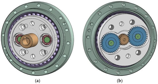
Figure 2.
Three-dimensional model of the RV-40E reducer. (a) RV-40E reducer input-end view; (b) RV-40E reducer output-end view.
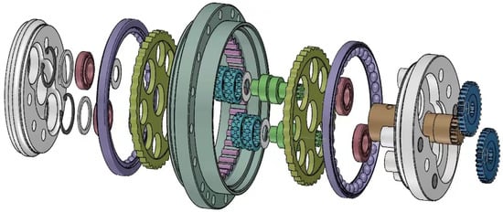
Figure 3.
Exploded view of the three-dimensional model of the RV-40E reducer.
2.4. Flexibility Treatment of the Virtual Prototype
To incorporate dynamic factors into the subsequent transmission error analysis, the relevant transmission parts must be treated as flexible bodies. Based on the structural characteristics of the transmitting gear train, the first-stage planetary gear transmission part rotates at a higher speed and bears a smaller impact on the output transmission error compared to the second-stage pin-cycloid gear transmission part, so that local deformations are relatively negligible. In order to add dynamic factors to the subsequent transmission error analysis, it is necessary to consider the relevant transmission parts as flexible bodies. According to its structural characteristics, the first-stage planetary gear transmission part rotates faster, and the torque it bears is smaller compared to the second-stage pin-cycloid gear transmission part, resulting in relatively negligible local deformations. The second-stage pin-cycloid gear transmission part transmits a larger torque and features a compact structure. The output part of the planet carrier is closely connected to the second-stage pin wheel, crankshaft, and cycloid wheel, which are treated as flexible bodies.
The primary steps for establishing the rigid–flexible coupling model of the RV reducer in RecurDyn are as follows:
- To enhance simulation efficiency, the three-dimensional model in SolidWorks (SW) was simplified without compromising the research results. This simplification involved ignoring fine structures such as chamfers and bolt holes, omitting gaskets, seal rings, and other non-critical parts, while retaining roller bearings and replacing them with bearing sleeves.
- The interference-free assembly is saved in the parasolid (x_t) format and imported into RecurDyn dynamics software. The resulting virtual prototype model is illustrated in Figure 4.
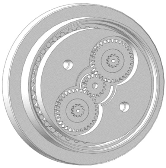 Figure 4. Rigid body virtual prototype modeling.
- 3.
- The material properties of the rigid body parts are defined. In RecurDyn software, the rigid body properties are specified based on the material properties and mass values. The material properties of each part of the RV reducer are listed in Table 2, where ρ represents density, E represents Young’s modulus, and ν represents Poisson’s ratio.
Table 2. Material properties of RV reducer parts.
- 4.
- The constraints are defined, including kinematic pairs and contact pairs, as detailed in Table 3. The crankshaft and the planet carrier are coupled by simulating the support bearings using the virtual bearing constraints provided by the software. Special attention is given to the positioning of the revolute joint in the eccentric section.
Table 3. Constraints and contact relationships in the virtual prototype.
- 5.
- Based on the applied constraints, the mesh function in RecurDyn is utilized to discretize the pin wheel, crankshaft, and cycloid wheel. Material properties are assigned to the corresponding parts, and the patch function is employed to establish surface contact, thereby completing the flexible body conversion. Finally, the rigid–flexible coupling model of the RV reducer is obtained as shown in Figure 5.
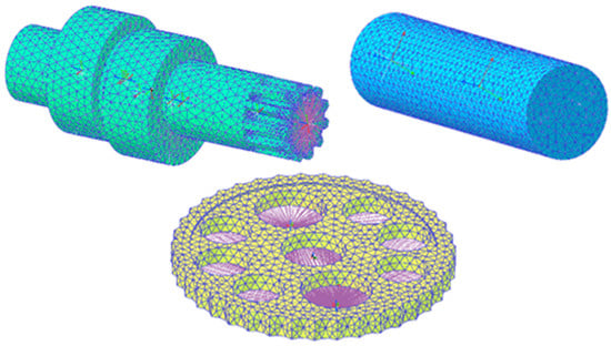 Figure 5. Meshing of flexible parts.
- 6.
- Setting the overall contact parameters of the model too high will slow down the calculation speed, while setting them too low will cause penetration between components. Therefore, setting appropriate contact parameters is crucial. This article refers to reference [21], which sets the stiffness to 30,000 N/m and the damping coefficient to 5 N·s/m to ensure the accurate transmission of calculation speed and virtual prototype motion and load, as shown in Figure 6.
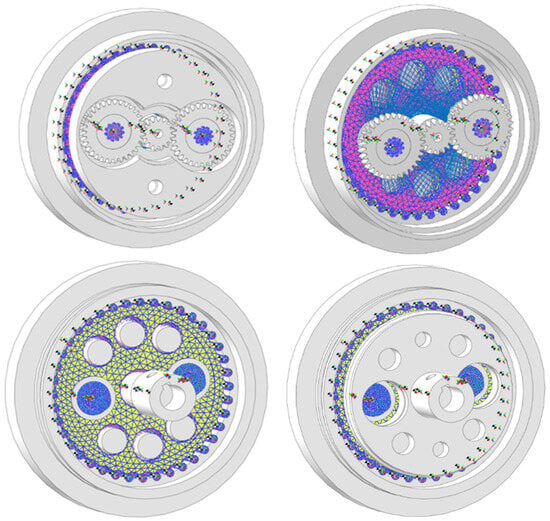 Figure 6. Rigid–flexible coupling model.
2.5. Reliability Verification of the Virtual Prototype
To validate the reliability of the virtual prototype methodology, it is essential to ensure that the transmission accuracy values obtained from the virtual prototype methodology for the RV-40E reducer are closely aligned with the transmission errors measured by the actual prototype test bench. Consequently, a test bench was constructed, and several groups of parts, drives, loads, and other samples were selected for transmission error measurement. The test bench primarily consists of servo motors, torque sensors, a circular grating encoder, etc. The experimental test bench, as illustrated in Figure 7, consists of the following components: two mounting brackets are fixed on the experimental platform, with an accompanying RV-40E reducer, torque sensor, and servo motor mounted on the left bracket, while the tested RV-40E reducer and encoder are installed on the right bracket. The input shaft of the tested reducer is likewise secured to the bracket. Upon activation of the servo motor, transmission error values under varying load conditions can be detected.
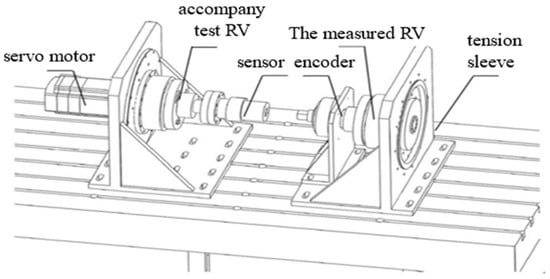
Figure 7.
Transmission accuracy test bench for the RV-40E reducer.
Five sets of RV-40E reducer parts were randomly selected for parameter measurement. After assembling the machine, five sets of transmission error data were obtained. Simultaneously, the corresponding five sets of transmission error data were acquired using the aforementioned virtual prototype. According to the transmission principle of the RV-40E reducer, the authors speculate that the sensitivity to output transmission errors is relatively small due to the runout of the central gear and planetary gear, the spacing between the cycloidal gear holes, and the spacing between the planetary carrier holes at both ends of the input and output. The radius of the central gear ring is selected as 11.094 mm, the radius of the planetary gear ring is 23.094 mm, and the spacing between the cycloid wheel holes and the planetary carrier holes is selected as 72.000 mm. The final transmission errors of the virtual prototype and experimental testing are shown in Table 4.
Table 4.
Comparison between virtual and actual results.
Five sets of RV-40E reducers were randomly assembled, and comparative analysis revealed that the average relative error between the transmission errors measured by the virtual and actual prototypes was 2.9%. The experimental results demonstrate that the relative errors of all reducers remain below 5%, confirming a high degree of consistency between the virtual and actual prototype measurements. The error between the numerical simulation results of the virtual prototype and the actual detection results of the experimental device does not exceed 5%, which is smaller than the difference in error when the author conducted multiple reproducibility tests on the RV-40E experimental device. Therefore, the transmission error data obtained from the virtual prototype simulation can be used as a substitute for the measured transmission error data. This approach enables calculating the transmission errors of the RV-40E reducer parts listed in Table 1, thereby reducing reliance on measured data.
2.6. Analysis of Factors Affecting Transmission Accuracy and Manufacturing Costs
The transmission accuracy and manufacturing cost of the RV-40E reducer are influenced by the accuracy levels of the purchased bearings as well as the width and position of the tolerance zones of eight types of self-manufactured parts. As the bearings and other purchased parts are constrained by their rated load capacity, the available types and accuracy levels are significantly restricted. By conducting multiple replacement tests and performing a basic cost analysis, it is relatively straightforward to determine the types and accuracy levels of these purchased parts, and it will not be discussed in detail later. However, determining the tolerance zone width and position of the eight types of self-manufactured parts remains challenging due to the complexity of influencing factors, making the rationality of the selected values difficult to justify. Therefore, this study employs orthogonal experiments and virtual prototype simulations to determine the values of these parameters. Following the orthogonal experiments on the influencing factors and key determinants of the RV-40E reducer’s output transmission accuracy and based on the sensitivity analysis of accuracy influence and the cost-effectiveness of the manufacturing process, this study proposes recommended values for the tolerance zone width and position of the eight types of self-manufactured parts.
Based on the working principle and structural composition of the RV-40E reducer, this study conducts a reverse analysis of the tolerance values of eight parts from the output transmission accuracy. The primary factor directly affecting output transmission accuracy is the rotational error of the output-end planet carrier, followed by the accuracy levels of two angular contact ball bearings supporting the output-end planet carrier, and then the installation errors of the planet carrier itself. Other contributing factors include the installation accuracy of four tapered roller bearings connecting the planetary carrier, four cylindrical roller bearings supporting the cycloid wheel and pin wheel, as well as the cycloid transmission accuracy, crankshaft transmission accuracy, and planetary gear transmission accuracy. Thus, multiple factors influence the output transmission accuracy and manufacturing cost of the RV-40E reducer.
Apart from enhancing transmission accuracy and reducing manufacturing costs through selecting externally purchased bearings, it is also essential to optimize the tolerance levels of the eight self-manufactured parts to further enhance transmission accuracy and reduce manufacturing costs. Since the first stage of planetary gear transmission accuracy primarily affects the instantaneous speed variation in the crankshaft, and the planetary gear speed is more than 40 times that of the planet carrier or the output speed, the radial runout and other errors of the input shaft in the first stage and the planetary gear have a negligible impact on output accuracy and can thus be disregarded. Likewise, the influence of the dimensional errors in the holes and shoulders of the angular contact ball bearings supporting the planet carrier, the tapered roller bearings supporting the crankshaft, and the cylindrical roller bearings supporting the cycloid wheels can be temporarily negligible or not considered based on the rough calculation by virtual prototype.
Hence, this study primarily investigates the influence of the tolerance values of the eight self-manufactured parts of the RV-40E reducer on output transmission accuracy. Table 5 shows the tolerance design values of 8 self-made parts of the RV-40E reducer currently provided by a manufacturer. Subsequently, the Latin hypercube sampling method and virtual prototype simulation calculation will be applied within the tolerance range of each part, and single-factor experiments and orthogonal experiments will be conducted to analyze the sensitivity of 10 tolerances of 8 parts to the output transmission accuracy and the reasonability of the design of 10 tolerance values.
Table 5.
Quality characteristics and tolerances for design of experiment.
2.7. Single-Factor Experiment Analysis of Reducer Part Tolerances
Using the virtual prototype of the RV-40E reducer, the 10 quality characteristic parameters listed in Table 5 were sampled with Latin hypercube sampling within their respective interval ranges to compute the output transmission error. The corresponding results are presented in Table 6 by a single-factor design of experiment (DOE).
Table 6.
Parameter values of quality characteristics using single-factor DOE (mm).
For each of the ten quality characteristic parameters of the parts, a single-factor experiment is performed to determine the sensitivity of each parameter to transmission error or transmission accuracy. When employing the virtual prototype to compute the output transmission error, the quality characteristics of the experiment factors are assigned values based on the data in Table 6, while those of the remaining factors are assigned representative values. The representative value corresponds to the median value of the existing tolerance range of the RV-40E reducer, and the final results of the single-factor experiment are presented in Table 7. The virtual prototype calculates the transmission error ∆φ value and range R value for the input shaft, planetary gear, and crankshaft, and pin-wheel housing 7 times each, and for the cycloid wheel, pin wheel, input-end planet carrier, and output-end planet carrier 5 times each.
Table 7.
Transmission error results based on virtual prototype and single-factor experiment.
The results indicate that the radial runout of input shaft gear, the radial runout of planetary gear, the hole center distance of the cylindrical roller bearing of the cycloidal wheel, and the center distance error of the input and output planet carrier bearing holes have a relatively minor influence on the output transmission error or exhibit insensitivity to it. Moreover, no consistent regular variation in the output transmission error is observed with changes in the input parameter values. Therefore, it is recommended to maintain the original width and position of their tolerance zones.
However, the crankshaft eccentric distance error, the modification of the moved distance and the equidistant parameters of the cycloidal wheel, the radial runout of the center circle of the pin wheel within the pin-wheel housing, and the radius error of the pin wheel exert a more pronounced and sensitive effect on the output transmission error. When the eccentric distance error of the crankshaft is zero, the output transmission error remains low. However, as the eccentric distance error of the crankshaft increases, the transmission error rises significantly. Given the constraints of existing processing equipment, it is recommended to temporarily maintain the original width and position of the tolerance zone for the crankshaft. The modifications to the moved distance and equidistant parameters of the cycloidal wheel must be strictly controlled at 0.012 mm and 0.020 mm, respectively, as even slight deviations can cause significant variations in the output transmission error. Therefore, it is advised to maintain the original width and position of their tolerance zones.
The pin-wheel ring radial runout of the pin-wheel housing and the pin-wheel radius error are also highly sensitive to transmission error, with their variations either amplifying or compensating for each other to some extent. Therefore, efforts should be made to control these two errors by improving the machining accuracy of the pin-wheel radius while appropriately relaxing the machining difficulty associated with the runout tolerance of the pin-wheel housing’s pinion center circle. Meanwhile, the original tolerance designs for the pin-wheel ring radial runout and the pin-wheel radius should be temporarily maintained. In summary, the results of the single-factor experiment indicate that the tolerance values of the 8 parts of the RV-40E reducer are reasonable.
2.8. Orthogonal Experiment Analysis of Reducer Part Tolerances
Given the varying degrees of influence of each sensitive characteristic, to enhance the transmission accuracy of the RV-40E reducer while reducing manufacturing costs in accordance with product quality requirements and process constraints, the optimal allocation of individual characteristic tolerances is essential. To this end, the L16 (45) orthogonal table was selected to design the experimental program, as presented in Table 8.
Table 8.
Transmission error results based on virtual prototype and orthogonal experiments.
In Table 8, K1, K2, K3, and K4 represent the average transmission errors corresponding to four different levels of each factor, while R denotes the maximum extreme difference resulting from the four level selections, which represents the impact of factor variation on the output transmission error. It is evident that the crankshaft eccentric distance error (∆a), moved distance modification error (∆rp), equidistance modification error (∆rrp), pin-wheel ring radia6l runout error of the pin-wheel housing (∆rb), and pin-wheel radius error (∆rr) exert a significant impact on the output transmission error of the RV-40E reducer. The influence of changes in the existing tolerance range on the output transmission error exhibits a similar trend.
Under the current production equipment capabilities and quality accuracy requirements, the tolerance bandwidth and position data in Table 1 are relatively well justified, indicating that the RV-40E reducer designers possess substantial experience, allowing the design to effectively balance transmission accuracy and economic feasibility. A more rigorous and precise evaluation of the reasonableness of the parameter values of the eight types of self-manufactured parts in the RV-40E reducer would require a more precise virtual prototype to compute additional transmission error data for a thorough analysis of the width and position of the tolerance zones. However, due to constraints related to the quality of purchased parts and the accuracy of the virtual prototype model, such an analysis is currently deemed unnecessary.
3. Results
The tolerance values of externally purchased components, such as bearings, are determined based on their accuracy levels. The transmission error can be calculated by combining virtual prototyping, and the accuracy level can be selected through single-factor testing to achieve the desired transmission error. The accuracy levels of bearings mainly include several accuracy level standards, such as C, D, E, G, etc. For high-accuracy RV-40E reducers, C-level or D-level bearings can be selected as needed, while for ordinary accuracy RV-40E reducers, C-level or D-level bearings can be selected as needed. Whether the selection of bearings is reasonable can be verified by simply testing the transmission accuracy through trial assembly.
The final optimized design results of the quality characteristic parameter tolerance values of RV-40E reducer parts are shown in Table 9. Due to the fact that the RV-40E reducer is designed based on various other models of RV reducers, the tolerance values in Table 1 should be relatively reasonable and basically consistent or similar to the optimized tolerance values in Table 8. Therefore, there are only two differences between Table 9 and Table 1, which are the compression of the eccentric distance tolerance bandwidth of the crankshaft from 0.006 mm to 0.004 mm, and the compression of the equidistant modification tolerance of the cycloidal gear from 0.006 mm to 0.004 mm. The eccentricity of the crankshaft changes from to , the equidistant modification amount of the cycloid gear changes from to , and the machining accuracy has been improved due to the low-cost goal.
Table 9.
Tolerance values after optimized design for RV-40E reducer parts.
4. Discussion
This article systematically validates the methodology for component accuracy selection and tolerance design in the newly developed RV-40E reducer. The research focuses on two key aspects: accuracy class selection for purchased components, such as bearings, and tolerance design for manufactured parts, such as gears. A multi-software virtual prototype was developed through the integration of SolidWorks, RecurDyn, and Adams platforms to predict transmission errors with ≤5% deviation from experimental measurements.
Experimental validation using five physical prototypes confirmed the virtual model’s accuracy, with simulation results deviating ≤5% from the measured transmission errors. Building on this validation, single-factor and orthogonal experimental analyses were conducted. Single-factor analysis provided the preliminary identification of key parameter sensitivities and their spatial influence distributions, while the orthogonal experiment enhanced sensitivity discrimination accuracy by compensating for measurement uncertainties.
For externally purchased components, such as bearings, a transmission-error-driven accuracy selection strategy was developed. Bearing accuracy classes (C, D, E, and G) were evaluated through application-specific selection criteria: Class C/D bearings for high-accuracy applications and Class E/G bearings for standard applications. Trial assembly and error testing validated the appropriateness of these selections.
For manufactured components such as cycloidal gears, sensitivity-based tolerance optimization was implemented through the simulation-guided optimization of both tolerance bandwidth and position. Current limitations include incomplete manufacturing cost data acquisition (due to proprietary process/equipment constraints), which partially constrained the tolerance optimization outcomes presented in Table 9. Future work should enhance virtual model fidelity and incorporate production cost data for cost-constrained accuracy/tolerance co-optimization.
Author Contributions
Conceptualization, methodology and project administration, S.J.; writing—original draft and developing software, J.S., B.W. and F.Y.; supervision and data curation, Y.W. All authors have read and agreed to the published version of the manuscript.
Funding
This research was funded by the National High-tech R&D Program of China (Grant. No. 2025AA043002) and the National Natural Science Foundation of China (Grant No. 51605442).
Institutional Review Board Statement
Not applicable.
Informed Consent Statement
Not applicable.
Data Availability Statement
The data presented in this study are available on request from the corresponding author. The data are not publicly available due to corporate data privacy.
Acknowledgments
The authors thank the Zhejiang Shuang Huan Transmission Machinery Co., Ltd. for providing a research site for the RV-40E reducer production.
Conflicts of Interest
The authors declare no conflict of interest.
References
- Yue, H.; Wu, X.; Shi, Z.; Zhang, Y.; Ye, Y.; Zhang, L.; Fu, Y. A comprehensive cycloid pin-wheel accuracy reducer test platform integrated with a new dynamic measurement method of lost motion. Metrol. Meas. Syst. 2022, 29, 207–229. [Google Scholar]
- Li, X.; Li, C.; Wang, Y.; Chen, B.; Lim, T.C. Analysis of a cycloid speed reducer considering tooth profile modification and clearance-fit output mechanism. J. Mech. Des. 2017, 139, 033303. [Google Scholar] [CrossRef]
- Yang, Y.; Zhou, G.; Chang, L.; Chen, G. A modelling approach for kinematic equivalent mechanism and rotational transmission error of RV reducer. Mech. Mach. Theory 2021, 163, 104384. [Google Scholar] [CrossRef]
- Ran, Y. Analysis of Transmission Accuracy for RV Reducer. Master’s Thesis, Chongqing University, Chongqing, China, 2015. [Google Scholar]
- Wei, Z.; Zhou, J.; Cui, Q.; Jia, J.; Zhang, R.; Liu, G. A method to analyze dynamic transmission error of RV reducer considering machining error and flexible factors. Xi’an Jiaotong Univ. 2023, 57, 161–172. [Google Scholar]
- Xu, L.; Xia, C.; Yang, B. Analysis and test on dynamic transmission errors of RV reducers under load conditions. China Mech. Eng. 2023, 34, 2143–2152. [Google Scholar]
- Wang, H.; Fu, W.; Fang, K.; Chen, T. Transmission characteristics of an RV reducer based on ADAMS. J. Mech. Sci. Technol. 2024, 38, 787–802. [Google Scholar] [CrossRef]
- Li, W.; Li, X.; Tang, X.Y. Study on building a prototype of robot used RV reducer. In Proceedings of the WEC 2004, Shanghai, China, 2–6 November 2004; pp. 222–227. [Google Scholar]
- Zhang, Y.; Chen, Z.; He, W. Virtual prototype simulation and transmission error analysis for RV reducer. J. Appl. Mech. 2015, 789, 226–230. [Google Scholar] [CrossRef]
- Jiang, Z.; Zhang, X.; Liu, J. A reliability evaluation method for RV reducer by combining multi-fidelity model and Bayesian updating technology. IOP Conf. Ser. Mater. Sci. Eng. 2021, 1043, 052038. [Google Scholar] [CrossRef]
- Liu, H.; Qin, X.; Huang, J.; Wu, R. Simulation of virtual prototype and research of transmission accuracy for RV reducer. J. Mech. Transm. 2016, 5, 55–60. [Google Scholar]
- Li, H.; Xu, H.; Wu, k. Analysis of transmission of RV reducer based on orthogonal experiment. J. Mech. Transm. 2017, 41, 71–76. [Google Scholar]
- Xi, Y.; Zhang, P.; Bu, W.; Hua, B.; Wang, Z.; Liu, X. Analysis of teeth clearances in robotic high accuracy RV reducer based on ADAMS. Chin. J. Constr. Mach. 2015, 13, 509–514. [Google Scholar]
- Xi, Y.; Yuan, L.; Zheng, Y.; Li, M. Research on Dynamic Simulation of RV Reducer for Robot Based on Adams. Chin. J. Constr. Mach. 2018, 16, 42–48. [Google Scholar]
- Wang, Z.; Xu, R.; Pan, J.; Chen, Q.; Zhang, J.; Wang, J. Effect of multifactor interaction on the accuracy of RV reducers. Int. J. Rotating Mach. 2023, 2023, 5692229. [Google Scholar] [CrossRef]
- Xu, L.; Wu, Y. Investigation of the dynamic transmission accuracy of an industrial robot joint RV reducer under variable situations. Multibody Syst. Dyn. 2025, 63, 1–38. [Google Scholar] [CrossRef]
- Gao, S.; Zhang, Y.; Li, Y.; Wang, Z. Piecewise modification of cycloidal gear in RV reducer: Application of spline interpolation theory and comparison with a combination modification optimization method. Int. J. Precis. Eng. Manuf. 2025, 26, 195–208. [Google Scholar] [CrossRef]
- Liu, Y.; Lei, F.; Ma, Q.; Zhao, Z.; Zhang, Z.; Wei, N. Analysis of co-axiality transmission efficiency vector model of RV reducer based on ADAMS. J. Phys. Conf. Ser. 2021, 2137, 012026. [Google Scholar] [CrossRef]
- Han, L.; Wang, H.; Wang, Y.; Zhao, J. Simulation research of rotary vector (RV) reducer bearing based on rigid-flexible coupling. J. Eng. Res. 2023, 24, 29–34. [Google Scholar] [CrossRef]
- Wang, S.; Deng, X.; Feng, H.; Ren, K.; Li, F.; Liu, Y. Dynamic simulation analysis and experimental study of an industrial robot with novel joint reducers. Multibody Syst. Dyn. 2023, 57, 107–131. [Google Scholar] [CrossRef]
- Wang, H.; Shi, Z.; Yu, B.; Xu, H. Transmission performance analysis of RV reducers influenced by profile modification and load. Appl. Sci. 2019, 9, 4099. [Google Scholar] [CrossRef]
- Tao, Y.; Liu, H.; Wu, M.; Zheng, N.; Pei, J. The effect of cycloid gear wear on the transmission accuracy of the RV reducer. Machines 2024, 12, 511. [Google Scholar] [CrossRef]
- Wu, K.Y.; Shih, Y.P.; Lee, J.J. Kinematic error analysis of the rotor vector gear reducer with machining tolerances. J. Braz. Soc. Mech. Sci. Eng. 2020, 42, 566. [Google Scholar] [CrossRef]
- Cao, D. Research on Tolerance Design Method for Key Components of RV Reducer. Master’s Thesis, Chongqing University, Chongqing, China, 2018. [Google Scholar]
- Ahn, H.-J.; Choi, B.M.; Lee, Y.H.; Pham, A.-D. Impact analysis of tolerance and contact friction on a RV reducer using FE method. Int. J. Precis. Eng. Manuf. 2021, 22, 1285–1292. [Google Scholar] [CrossRef]
- Chen, S.; Su, W. Tolerance optimization design of RV reducer’s cycloid-pin gear pair considering multiple targets. In Proceedings of the International Conference on Optical Technology, Semiconductor Materials, and Devices, OTSMD 2022, Longyan, China, 28–30 October 2022; pp. 130–135. [Google Scholar]
- Xie, X.; Xu, H.; Guan, T. Tolerance analysis and optimization of static assembly of RV reducer based on 3DCS. J. Mech. Transm. 2019, 43, 150–153. [Google Scholar]
- Xie, X.; Xu, H. Optimization of part tolerance of RV reducer based on genetic algorithm. J. Mech. Transm. 2020, 44, 77–83. [Google Scholar]
- Wang, Q.; Chen, X.; Ye, X. Tolerance Grouping Matching Backlash Analysis of Accuracy Reducer based on Monte Carlo Simulation. J. Mech. Transm. 2019, 43, 167–171. [Google Scholar] [CrossRef]
- Tran, T.L.; Pham, A.D.; Ahn, H.-J. Lost motion analysis of one stage cycloid reducer considering tolerances. Int. J. Precis. Eng. Manuf. 2016, 17, 1009–1016. [Google Scholar] [CrossRef]
- Li, Y.; Su, Y.; Wang, S. Optimization of tooth profile modification amount and manufacturing tolerance allocation for rotate vector reducer under reliability constraint. J. Mech. Des. 2024, 146, 073401. [Google Scholar] [CrossRef]
- Wang, X.; Li, L.; Ye, J.; Yang, X.; Wang, H.; He, X. Positioning accuracy prediction and tolerance allocation of cycloid reducers based on a BDTCA model. J. Mech. Des. 2023, 145, 073401. [Google Scholar] [CrossRef]
- Zhang, B.; Zhou, J.; Cui, Q.; Xu, W.; Zhou, Y.; Zhong, F. Position error adjustment method for RV reducers based on state space model. Tenth Int. Conf. Mech. Eng. Mater. Autom. Technol. 2024, 13261, 127–136. [Google Scholar]
- Liu, Z.; Xu, H.; Sa, G.; Lyu, Y.; Tan, J. A comparison of sensitivity indices for tolerance design of a transmission mechanism. J. Zhejiang Univ. Sci. A 2022, 23, 527–542. [Google Scholar] [CrossRef]
Disclaimer/Publisher’s Note: The statements, opinions and data contained in all publications are solely those of the individual author(s) and contributor(s) and not of MDPI and/or the editor(s). MDPI and/or the editor(s) disclaim responsibility for any injury to people or property resulting from any ideas, methods, instructions or products referred to in the content. |
© 2025 by the authors. Licensee MDPI, Basel, Switzerland. This article is an open access article distributed under the terms and conditions of the Creative Commons Attribution (CC BY) license (https://creativecommons.org/licenses/by/4.0/).