Article

Characterisation of the Pump-Suction Flow Field of Antarctic Krill and Key Influencing Factors

1
Fishery Machinery and Instrument Research Institute, Chinese Academy of Fishery Sciences, Shanghai 200092, China
2
Joint Research Laboratory for Deep Blue Fishery Engineering Equipment Technology, Pilot National Laboratory for Marine Science and Technology (Qingdao), Qingdao 266237, China
*
Author to whom correspondence should be addressed.
Appl. Sci. 2025, 15(11), 5836; https://doi.org/10.3390/app15115836
Submission received: 14 April 2025 / Revised: 19 May 2025 / Accepted: 20 May 2025 / Published: 22 May 2025

Abstract

:
To address the problem of high damage rates and low efficiency during Antarctic krill pumping, this study used Discrete Phase Modelling (DPM) computational fluid dynamics (CFD) to analyse how krill–water mixing ratios and centrifugal pump speeds affect flow dynamics and mechanical stresses. The simulation results show that a 4/6 krill-water ratio and a rotation speed of 550–600 rev/min minimise wall collision forces and krill crowding forces, thereby significantly reducing damage. Lower rotation speeds result in uneven force distribution, while higher rotation speeds have the potential to cause localised stress peaks. A mixing ratio deviation of 4/6 increases wall collisions (3/7) or interkrill crushing (5/5). These results provide a feasible guide for the design of krill suction pumps that will improve krill survival and contribute to the sustainability of the Antarctic krill fishery.

1. Introduction

Antarctic krill (Euphausia superba, hereafter krill) is currently the largest single species of marine biological resources known to be commercially exploitable. It has a biomass of 650–1000 million tons. In the Southern Ocean, krill are an integral part of the marine ecosystem and are dependent on sea ice during their early life stages. They are a primary prey source supporting a diverse assemblage of marine predators including whales, seals, penguins, and flying seabirds. They also play a role in nutrient cycling and are the target of the Southern Ocean’s largest fishery [1,2,3,4,5]. It is considered to be a significant reservoir of protein for human consumption and has the potential to become China’s second ocean fishery. Krill is a rich source of nutrients, including phospholipids, polyunsaturated fatty acids, and astaxanthin. The development of high-value-added products, including functional foods, pharmaceuticals, health products, and high-end aquaculture feeds, is a potential outcome of this research [6,7]. The prospects for the development of a high-value emerging marine biological industry are significant. In the context of industrial krill fishing, the configuration of the pumping apparatus constitutes a pivotal scientific concern, determining the biological integrity of the target species and the economic viability. During operation, the pumping device utilises a high-speed rotating impeller to generate negative pressure, thereby drawing the krill–water mixture into the pipe. Inadequate or improperly configured pump speed, flow rate, or pressure parameters are likely to result in two primary issues during the fishing process. Firstly, excessive mechanical forces may cause the krill shells to fracture, leading to a 20% to 35% loss of individual integrity [8]. Secondly, the fragmented krill tissue may impede the filtration system, necessitating frequent stoppages for cleaning, which will increase maintenance costs.
The centrifuge is the primary structural element of the krill pump. The centrifuge possesses a complex internal mechanical structure, which engenders an extremely complicated flow field inside. The interaction between impeller rotation and surface curvature gives rise to a multitude of phenomena, including separation, reflux, and secondary flow, thereby further augmenting the intricacy of the fluid flow within the impeller [9,10,11,12,13]. Huang Mingji et al. [14] used a simulation to characterise the drag reduction performance of a centrifugal pump using its torque variation, considered the influence law of structural parameters such as the morphology of the bionic structure, the cross-section shape and the characteristic height, and revealed the influence mechanism of the bionic structure on the drag reduction characteristics of the centrifugal pump through the analysis of the vane surface velocity contour. Wu Shaoke et al. [15], in order to further study the transient working condition of high-specific-rpm high-power centrifugal pumps, applied flowmaster software to build a centrifugal pump operation model, and the boundary conditions were set up according to the actual measured parameters to simulate and compare with the test results, and the simulation analysis was carried out for the different starting modes of the pumps in a credible manner to quantify the advantages of a start-up process. The merits of initiating the process, predicated on the characteristic curves of instantaneous starting speed, flow rate, power, and outlet pressure of the centrifugal pump being obtained at varying valve openings and then analysed by quantitative normalisation. Sorguven et al. [16], based on the detailed analysis of Large Eddy Simulation (LES), carried out an in-depth analysis on the mechanism of loss generation in in-line centrifugal pumps operated under real conditions. The results showed that there is a strong interaction between the components. Xue Xiaoyu et al. [17] selected the standard k- ε turbulence mode and SIMPLE algorithm to study the flow characteristics of the internal flow field of two electric submersible centrifugal pumps with different vane-guide wheel structures under different working conditions and to investigate the mechanism of the influence of the impeller structure on the external characteristics of the pump, which provides a theoretical basis for the selection and optimisation of the pumps under different working conditions. Wei et al. [18] selected the low-specific-speed centrifugal pump as the object of study. Through a combination of numerical calculations and experimental validation, the impact of gap structure on the performance of centrifugal pumps was investigated. The results demonstrated that utilising smaller gap widths of gap drainage structures can enhance the performance of centrifugal pumps with low specific speeds. However, it was also observed that leakage from the gap would reduce the head of the centrifugal pump. Zhang et al. [19] systematically investigated the radial force of the impeller, pressure pulsation, deformation, and vibration of the main shaft under nine distinct flow conditions from the perspective of unstable flow inside the centrifugal pump. They established a correlation between the fluid flow inside the centrifugal pump and the external rotor structure vibration, thereby providing a theoretical foundation for the vibration reduction design and safety monitoring strategy of the centrifugal pump. In the study of solid–liquid two-phase flow in centrifugal pumps, Blais B. et al. [20,21,22] combined theory and engineering practice, applied the computational fluid dynamics–discrete element method (CFD—DEM) algorithm in the mixer, analysed the effects of particle properties on mixing dynamics, and through the test, proved that the method has a certain reliability in the simulation of rotating machinery. Satish K. et al. [23] tested a multi-stage centrifugal slurry pump and found that the head and efficiency of the pump depended largely on the concentration of the solid phase in the slurry. Huang S. et al. [24] used CFD—DEM coupled simulation to calculate the unsteady solid–liquid two-phase flow in a centrifugal pump and obtained the trajectory and solid-phase volume rate of the 1.0–3.0 mm particle group in the centrifugal pump. Nicolò Beccati et al. [25] took the dredging pump as an object of study, combined CFD with experiments, and carried out a more in-depth study of the solid–liquid two-phase flow, and the results proved that modelling the solid–liquid two-phase flow using Eulerian–Eulerian methods can analyse the performance level of existing dredging pumps or predict the losses of new dredging pump designs.
With the transformation of the global fishery resources development mode in the direction of intensification and intelligence, the rapid development of new facilities and equipment, such as deep-sea aquaculture platforms [26,27,28,29], has prompted the live fish catching link to become a key node of the modern fishery industry chain. In this context, centrifugal pump technology designed based on the principle of fluid dynamics is gradually widely used in fish suction pumps after engineering improvement [30]. In comparison with conventional manual fishing methods, the utilisation of a suction pump offers several advantages. The labour intensity of the former is notably higher, with a daily operation capacity of a single vessel limited to 3 tons. Furthermore, the catch damage rate is observed to be between 15 and 20 per cent, and the operating efficiency is low, with a handling capacity of less than 2 tons per hour. In contrast, the suction pump has the capacity to increase the efficiency of live fish delivery to 10–15 tons per hour. Additionally, it can control the mechanical damage rate at less than 3 per cent, thereby greatly improving the level of mechanisation. This is achieved by effectively reducing the labour intensity and enhancing the quality of fish and fishing efficiency. It is imperative to reduce labour intensity while concomitantly enhancing the quality of the catch and fishing efficiency. Chu Shupo et al. [31] utilised SolidWorks to conduct a three-dimensional solid modelling investigation of the research design for a double-runner parallel fish suction pump. The study’s findings provide a theoretical foundation for the research. Long Xinping et al. [32] studied the protection of the fish body in a fish suction pump. Sui Barge et al. [33] designed and developed a fish suction pump for large trawlers fishing for mackerel in the South Pacific Ocean, which can take fish directly from the net bag of a large ocean-going trawler. The suction pump has a fast suction speed and good suction effect, which avoids the complicated operation process of dragging the net sac to the deck and dragging the sac on the deck, thus reducing the breakage rate of the net gear. Fang Xiong [34] and others established a three-dimensional shrimp suction pump model and completed the prototype development for the transformation and upgrading of the large-scale continuous Antarctic krill fishing industry to provide important technical support. Liu et al. [35], in the case of the centrifugal fish suction pump, through the CFD numerical calculation method, analysed the impeller in the same case and the different shapes of the volute spiral case on the efficiency of the fish suction pump for the fish suction pump volute spiral case design and optimisation, which provides a reference basis. The Z-type live fish transfer pumps developed by Matsusaka Manufacturing Company in Japan effectively reduce the damage rate of fish [36]. The TRANSVAC vacuum fish pump produced by the American company “ETI” [37] has a pumping capacity from 300 t/h to 360 t/h and a power from 23 kW to 190 kW, and the fish body is not damaged. However, the price is high, and it is generally used in large net box aquaculture farms. The Canadian company CanaVac has designed a set of fish suction equipment for aquaculture fishing [38], which is installed with special valves to prevent physical damage to the fish, the handmade soft rubber is smooth and durable, and the inner wall is polished to keep the fish warm and allow it to pass through. Fish gently enter the pump body at a low speed without contact with moving parts such as impellers, check valves, or high-pressure water flow and always exit the tank with their head or tail, greatly reducing the likelihood of collision damage or fish death. The centrifugal suction pump developed by the Icelandic company VAKI [39] allows for the gentle and rapid transfer of salmon, tilapia, etc. This pump has 300% less stress on the fish during the process compared to the more traditional pumping processes. In addition, the suction pump is equipped with various functions such as a counting device, fish water separator, and weighing function, and the system is lightweight and easy to install and move on site, making it adaptable to more extensive aquaculture environments.
At present, research on the design parameters and internal flow field of the suction krill pump has already yielded some results. However, the current use of suction krill pumps still exists, the krill body damage rate is high, the operating efficiency is low, the body is bulky, and the energy consumption is high. The krill suction pump may have more similarities to the fish suction pump in terms of the operating principle. However, the geometry of the krill body, force characteristics, transport conditions, etc., have led to the decision to use suction krill pumps and suction fish pumps due to the existence of large differences in the power structures. For the same centrifugal pump operating parameters, the survival rate of krill will be significantly lower than live fish. In the high-speed operation of the centrifugal pump, krill can withstand the limit of pressure less than live fish. The integrity of the krill body will be significantly compromised. Based on the above analysis, in order to further study the krill body in the pump-suction process of the state of motion and the structure of the pump flow field, this thesis is based on the theory of computational fluid dynamics, the use of the less-used DPM (discrete-phase model) to carry out the krill suction pump internal flow field characterisation, the study of the krill and water mixing ratio, the centrifugal pump rotation speed, and other important influencing factors on the krill body force. The research results can provide a theoretical basis for the selection and design of krill pumps and the transport conditions of Antarctic krill.

2. Materials and Methods

2.1. Control Equations

For incompressible viscous fluids, the fluid obeys the laws of the conservation of mass, the conservation of momentum, and the conservation of energy. In a Cartesian coordinate system, the effects of turbulent pulsations are ignored, and the fluid density is assumed to be constant. The conservation of mass and momentum equations take the form of the dimensionless continuity equation and the Navier–Stokes equations [40,41,42]. The equations for the conservation of mass and the conservation of momentum are expressed in the form of continuity and Navier–Stokes equations with differential forms:
u i t + u j u i x j = 1 ρ P x i + x j ( υ u i x j )
u i x i = 0
where ρ is the fluid density; P is the static pressure; t is the time; u i and u j are the flow rates in the direction of i and j , respectively; x i and x j are the Cartesian coordinates; υ is the dynamic viscosity coefficient.

2.2. Turbulence Modelling
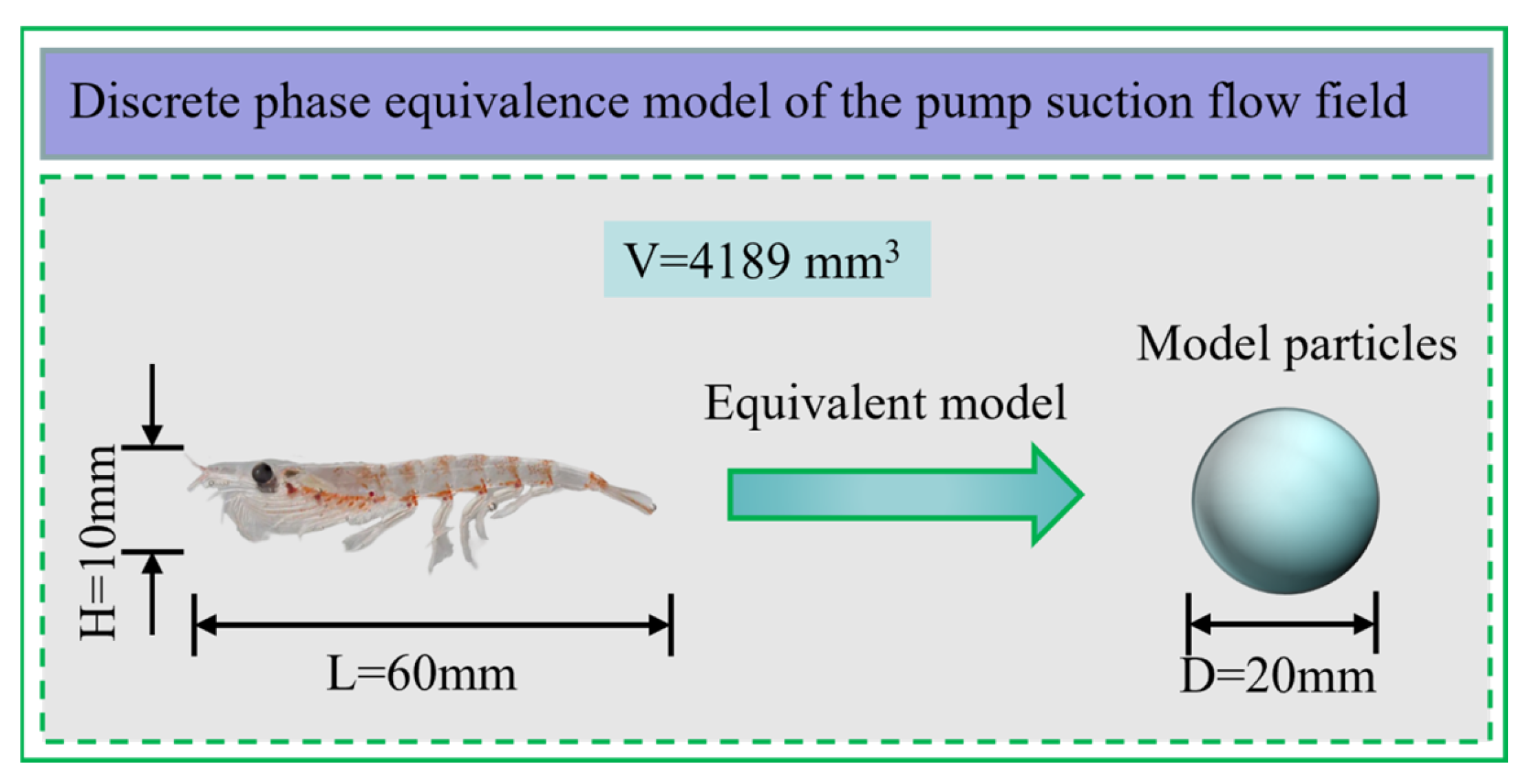
The k-ω SST model is mainly used to deal with compressible free shear flow problems and can show the flow of a near-wall free stream well [43]. Due to its low dependence on the far-field conditions and the high accuracy of the near-wall simulation, and the corresponding low mesh number requirement, the model is considered suitable for the simulation of flow separated by a blunt structure and has been widely used in recent years.
( ρ k ) t + ( ρ k u i ) x i = x j ( Γ k k x j ) + G k Y k + S k + G b ( ρ ω ) t + ( ρ ω u i ) x i = x j ( Γ k ω x j ) + G ω Y ω + S ω + G ω b Γ k = μ + μ t σ k Γ ω = μ + μ t σ ω μ t = α ( β i / 3 + ρ k / μ ω R k 1 + ρ k / μ ω R k ) ρ k ω
where G k and G ω are the turbulent kinetic energy generated by the mean velocity and the generation of a specific dissipation rate, respectively; Γ k and Γ ω are the effective diffusivities of k and ω , respectively, Y k and Y ω are the dissipations due to the turbulence of k and ω ; S k and S ω are the source terms; G b and G ω b are the diffusivity of k and ω , which is the effect of buoyancy on turbulence. σ k and σ ω are the turbulence Prandtl numbers for k and ω ; μ t is the turbulence viscosity; α is a coefficient whose value must be reduced when performing turbulence analysis at low Reynolds numbers. The purpose of reducing the value of the coefficient is twofold; firstly, it enables the calculation of turbulent viscosity, and secondly, it ensures that a low Reynolds number model with α = α = 1 is realised at high Reynolds numbers.
The k-ω SST model combines the advantages of the k-ω model in the near-wall region with those of the k-ε model in free flow, rendering the model more adaptable to the entire flow field. This hybrid characteristic enables the k-ω SST model to provide more accurate simulation results when dealing with devices such as krill suction pumps, which have complex geometries and flow characteristics. Furthermore, the SST model incorporates the transport of turbulent shear stresses in the turbulent viscosity calculation, thereby enhancing the prediction accuracy of the separated flow under complex flow conditions, such as the presence of a reverse pressure gradient or flow separation. In the context of the suction krill pumping system examined in this study, given the presence of the centrifugal force, it is deemed more appropriate to employ the k-ω SST turbulence model for the management of flow within the pump. Consequently, the k-ω SST turbulence model is employed in this calculation to ensure the study’s accuracy.

2.3. DPM Model

The body length of adult krill typically ranges from 42 mm to 65 mm, with the largest being 90 mm. The body length of juvenile krill is about 25 mm to 40 mm [44,45]. The body length of the krill studied in this paper is 60 mm, and the maximum thickness of the krill body is 10 mm, which is considerably smaller than the dimensions of a centrifugal pump. Krill are not fast swimmers and are usually found suspended in clusters in seawater. The body of the krill bends when stimulated, which can be calculated for a circle with a diameter between 12 and 20 mm based on the above lengths. For the purpose of a simulation analysis, krill is simplified as a spherical particle of equal volume with a particle diameter of 20 mm (Figure 1).
Currently, the main mathematical descriptions of CFD in the study of solid–liquid two-phase flow are categorised into three main computational techniques, namely the two-fluid model (Euler–Euler method), the discrete-phase model (Euler–Lagrange method), and the fluid-simulated particle method (Lagrange–Lagrange method). In the numerical simulation of solid–liquid two-phase flow in pumps, the Euler–Euler two-fluid model has significant limitations in resolving the interaction mechanism between particles, especially in accurately capturing the characteristics of particle collision dynamics. The continuous medium assumption of the model leads to significant numerical deviations when there is a localised increase in particle concentration in the flow field. In contrast, the Eulerian and Lagrangian coordinate systems allow the particles to be treated as independent entities and their dynamic behaviour to be resolved by the application of Newton’s second law of motion, while the fluid is treated as a continuous medium; the Continuous-Discrete-Phase Model (CDPM), described by the Reynolds-averaged Navier–Stokes (RANS) equations, is used. This approach allows for the exchange of momentum between the solid particles and the fluid. The representative models of this approach include the discrete-phase model (DPM) and the discrete element method (DEM). Pagalthivarthi, Zhang Desheng, and Li Bing et al. [46,47,48] conducted a more in-depth study of centrifugal pumps through the CFD-DPM coupling. The present study focuses on the movement of a mixture of krill and water when subjected to the action of a centrifugal machine. If the density of krill is close to that of water, the relative motion of krill and water is not significant. Given the modest mixing density of krill–water, both the DPM and DEM models are applicable [25,49]. The DEM model is known to require more time than the DPM model to calculate interaction forces and is moreover only applicable to small-scale systems. Therefore, the DPM model was used to ensure the reliability of results and enhance computational efficiency.
Fluent 2023 R1 predicts the trajectory of a discrete-phase particle (droplet or bubble) by integrating the force balance on it, which is described in the Lagrangian coordinate system. Its force balance equation can be written as the following equation [50]:
m p d u p d t = m p u u p τ r + m p g ( ρ p ρ ) ρ p + F
where m p is the mass of the particle, u is the velocity of the continuous phase, u p is the particle velocity, ρ is the density of the continuous phase, ρ p is the density of the particle, F is the added mass force, m p u u p τ r is the particle flow resistance (drag force), and τ r is the particle relaxation time.
τ r = ρ p d p 18 μ 24 C d R e
where μ is the molecular viscosity of the continuous phase; d p is the particle diameter; and R e is the relative Reynolds number, which is defined as
R e = ρ d p | u p u | μ
The DPM model solves the equations of the motion of the particles in Lagrangian coordinates as
d u p d t = F D ( u g u p ) + g ( ρ p ρ ) ρ p + F x
where F D is defined as the fluid resistance; that is to say, the force resulting from the velocity difference in the particles moving within the fluid; F x is the interaction force between particles or between particles in contact with a boundary.

2.4. Model Parameter

The centrifugal krill suction pump built according to the parameters of the relevant documents is shown in Figure 2.
The model was constructed using ANSYS 2023R1 Designmodeler 3D modelling software to facilitate enhanced interaction with Fluent. The target model comprises three components: an inlet pipe, a double impeller area, and an outlet pipe. The overall meshing of the model is accomplished through a combination of structured and unstructured meshes. The overall number of elements is 720,000, the number of elements of the impeller region is 430,000, and the number of elements of the flow field region of the pipe is 290,000. The distance from the first layer of the grid to the impeller wall is 2 mm, ensuring that the y+ value of the impeller wall tends to 1.
The lowermost part of the model area is designated as the krill–water mixing inlet and is set as the mass inflow inlet. The region on the right-hand side of the model area is designated as the outlet area and is set as the pressure outlet. The impeller is set on a slip mesh, while the remainder of the components are set on non-slip walls. The DPM model jet source is located in the inlet area, and the jet source type is set to source. All other components are set to default.
The SIMPLEC algorithm is utilised, the discrete phase is in second-order windward format, the residuals are converged to 10⁻6, and the transient simulation is performed with a simulation time of 0.01.
In the field of computational fluid dynamics (CFD), skewness is a metric employed for the evaluation of the quality of a mesh cell. This is achieved by quantifying its deviation from an ideal (regular) shape. The measurement of “unevenness” or “asymmetry” in a cell can have a substantial impact on numerical stability, solution accuracy, and convergence. The krill pump model is meshed, with a skewness of each part of the mesh below 0.01. It is imperative to note that the number of meshes should not be excessively large, owing to the influence of the particle volume fraction. While ensuring the calculation’s accuracy, the same method is employed to define the five sets of meshes, A, B, C, D, and E. The model with a krill–water mixing ratio of 3/7 and a rotational speed of 450 rev/min is selected for mesh independence analysis, and the maximum velocity obtained in the simulation is used as the basis for evaluating grid independence. The mesh-independent validation statistics table is shown in Table 1.
The maximum velocity of the flow field in the pump is shown in Figure 3, calculated by comparing these five meshes sets. The selection of Mesh C for numerical computation is informed by considerations of computational accuracy and available resources.

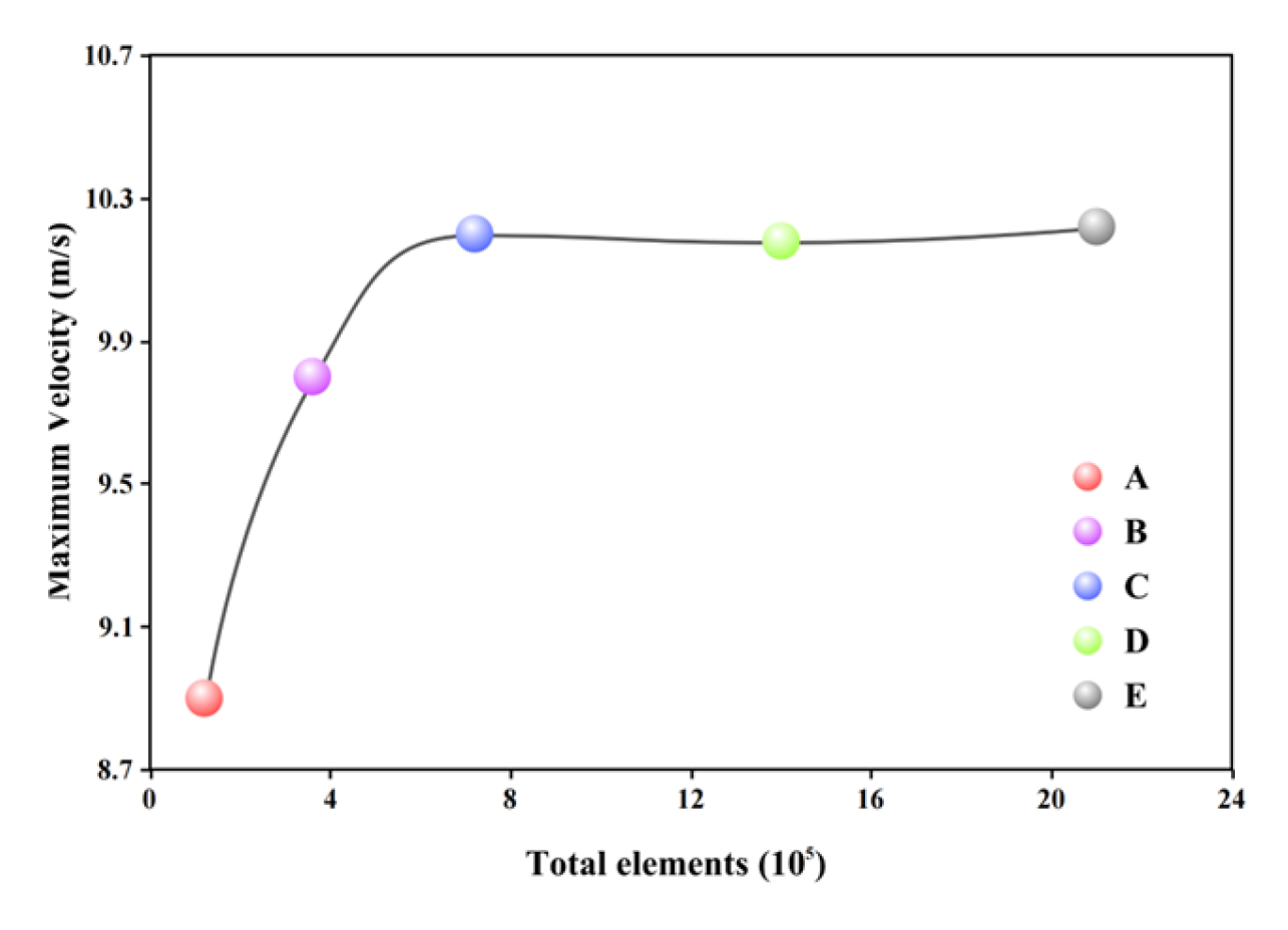
2.5. Verification of Results

As demonstrated in Refs. [35,51], the rotation of the impeller at high speed generates a pressure differential between the interior and exterior of the pump, thereby facilitating the amalgamation of fish and water. It has been demonstrated that both the fish and the water are subjected to positive air pressure, a finding that is in accordance with the results of the simulations. However, it has been demonstrated that fish are susceptible to severe injury from friction during transit through the pump mechanism, which can result in elevated mortality and disability rates. As demonstrated in Reference 34, the efficiency and survival of krill captured by suction pumps are influenced by the impeller rotation speed and water flow rate (a finding that aligns with the methodology employed in our study). Ref. [52] examined the internal flow field of a centrifugal krill suction pump, utilising the Fluent 2023R1 software for this purpose. The results demonstrated that the hydrostatic and velocity fields within the krill suction pump underwent minor alterations as the particle concentration (equivalent krill model) increased. Within the impeller channel, the particles were closer to the impeller’s working surface, resulting in more frequent collisions that damaged the transported krill. The results of this study align with the findings depicted in Figure 4.

3. Results

Relevant studies have shown that the possible factors affecting the damage rate of krill include the rotation speed of the impeller and the mixing ratio of krill–water. This study aims to simulate and analyse these two parameters to determine the synergistic effect of the two key variables, the mixing ratio of krill–water, and the rotation speed of the centrifugal pump on the performance of the pump. The simulation employs the VOF two-phase flow and DPM models to establish the ratio of krill–water, with the particle size set to replicate the dimensions of krill (20 mm). The ensuing simulation results are as follows.
Its lateral velocity in pump variation contour is shown in Figure 5, Figure 6 and Figure 7:
The horizontal velocity contours for the three krill–water mixing ratios of 3/7, 4/6, and 5/5 are displayed in the figure above. It is evident from the figure that the velocity within the pump body is distributed in a clearly uneven manner. The velocity is higher in the centre of the impeller and at the outlet of the centrifuge. Notwithstanding the varying krill–water mixing ratios, the velocity within the impeller’s proximity to the wall exhibits a consistent and gradual increase, indicating a notable enhancement in velocity. Prior to the centrifuge attaining 500 rev/min, a substantial change in the impeller velocity is evident, indicating a rapid growth phase. However, when the rotation speed exceeds 550 rev/min, the velocity change in the impeller centre becomes negligible and enters a slow change stage. The centrifuge outlet area exhibits a less significant change in velocity when compared to the impeller area, irrespective of the krill–water mixing ratio. However, it is evident that at rotation speeds below 550 rev/min, the outlet velocity distribution exhibits greater uniformity, resulting in a diminished squeezing force exerted on the krill by the wall surface. Conversely, at rotation speeds exceeding 550 rev/min, the flow at the outlet exhibits a pronounced tendency to deviate towards one side of the wall surface. This has the potential to result in a higher collision rate of krill with the wall surface in the outlet area, leading to an increased damage rate.
At a constant rotation speed, the velocity changes at the centre of the impeller and at the outlet of the centrifuge when the krill–water mixing ratio of 4/6 and 5/5 are compared. Although the impact is minimal, the velocity changes are considerably more moderate than the krill–water mixing ratio of 3/7, particularly the velocity changes at the impeller wall. This will reduce the collision between the krill and the wall and minimise the damage to the krill caused by extrusion. Nevertheless, it is challenging to ascertain the most appropriate krill–water mixing ratio solely based on velocity changes in the cross section. The degree of contact between the krill and the wall surface can be further elucidated by examining the longitudinal velocity contours in Figure 8, Figure 9 and Figure 10.
As is evident from the longitudinal section, the centrifugal effect influence is more pronounced in the inlet area, resulting in a more uniform velocity distribution. The experimental results demonstrate a positive correlation between the duration of krill body exposure within the centrifugal region and the resultant velocity increase in the outlet pipe section. This enhancement in velocity was observed to be consistent across all tested krill–water mixing ratios, with the velocity measurements in the outlet pipe section of the centrifuge system consistently exceeding the initial velocities recorded in the inlet pipe region. However, the velocity distribution becomes more chaotic. The increase in rotation speed renders the chaotic degree more significant. The chaotic fluid drives the krill body to disperse, increasing the probability of collision with the wall. When the rotation speed is low, the force between the krill and the wall is more uniform; however, when the rotation speed exceeds 500 rev/min, the velocity variation in the outlet area is more significant, and the krill is more likely to touch both sides of the wall. As the distance from the centre of the impeller increases, the velocity distribution gradually returns to a uniform trend. In the impeller’s centre, the velocity distribution exhibits a direct correlation with the rotation speed, demonstrating that as the speed of rotation increases, the velocity in this specific area also rises.
A comparative analysis of the effects of varying krill–water mixing ratios on the distribution of krill bodies following centrifugal movement reveals that, in the krill–water mixing ratios of 3/7 and 4/6, the krill bodies present in the exit area exhibit a heightened susceptibility to the influence of centrifugal flow, gradually gravitating towards the wall. It can be posited that the velocity distribution is more concentrated in the central area and that the velocity change on both sides of the wall is not as significant as that in the other two krill–water mixing ratios. This is evidenced by the distribution of velocities in the exit area being chaotic and the friction with the wall being more likely in the krill–water mixing ratio of 5/5. The velocity changes observed on both sides were less pronounced than those seen in the other two krill–water mixing ratios.
In order to analyse the specific changes in the flow rate in the suction krill pump in more detail, the maximum velocity for each condition is shown in Figure 11:
As demonstrated in Figure 10, the maximum velocity exhibited an upward trend as the rotation speed increased, though this growth was non-linear and decelerated gradually as the speed increased. In the three-krill–water mixture, the maximum velocity growth rate of the rotation speed shows a “single valley”. The rotation speed of 550 rev/min corresponds to a growth rate of 9.5%, 1.9%, and −7.3%, respectively, as the krill–water mixture ratio increases and decreases. It is noteworthy that at a krill–water mixing ratio of 5/5, the maximum velocity growth rate in the centrifuge at the optimum speed was negative. This is likely attributable to the fact that, following rotation, the krill bodies were more dense, thereby reducing the driving effect of the water flow on the krill bodies. At 550 rev/min, the maximum velocities in the pumps at 4/6 and 5/5 krill–water mixing ratios were almost identical, with the former being 10.5 m/s and the latter 10.1 m/s. In contrast to the krill–water mixing ratios of 3/7 and 4/6, the maximum velocities in the pumps at 5/5 krill–water mixing ratios, the 550 rev/min and 600 rev/min centrifuge velocities were found to be almost identical, at 10.1 m/s and 10.1 m/s, respectively. It is evident that an increase in the krill–water mixing ratio results in a decrease in centrifuge maximum velocity across all conditions, from 12.2 m/s to 10.1 m/s. The lowest velocity is observed in the case of a 5/5 krill–water mixing ratio, and the change in velocity is less pronounced than in the other two krill–water mixing ratios.
In order to visualise the damage to the krill body, the actual pressure exerted on all krill particles was compared, and the lateral and longitudinal krill body pressure changes are shown in Figure 12, Figure 13, Figure 14, Figure 15, Figure 16 and Figure 17:
The simulation of the DPM wall force lateral contour shows that, regardless of the krill–water mixing ratio, the impeller centre area of the krill aggregation area lacks significant changes, and with the increase in speed of the centrifuge, the krill body, under the action of stronger centrifugal force, gradually moves to the pump wall on both sides, and with the rotation speed lower than 550 rev/min, the krill body movement is biased to one side, the other side less, and the fabrication process is uncomplicated. The body of the krill is positioned laterally between the extrusion and the pump wall collision. At the rotation speeds of 550 rev/min and 600 rev/min, the body of the krill under the centrifugal force is investigated. The tendency of the distribution along the two sides of the more significant and less significant contact points of the pump wall is evident. It is clear that as the speed of the pump increases, the force of collision between the body of the krill and the pump wall also increases. Furthermore, an increase in the rotational speed of the force and the pump wall also results in an increase in the force of collision. It has been demonstrated that an increase in the rotation speed of the centrifuge results in the distribution of krill in the outlet region becoming gradually chaotic. When the rotation speed exceeds 550 rev/min, contact between the krill and the pump wall becomes more pronounced, and the density of krill in the region increases. This increase in density leads to a heightened probability of collisions between krill, with the likelihood of damage increasing.
It has been established that velocity contour analysis is distinct from the contour of collision force. The water mixing ratio of krill is of greater consequence, and when this is 3/7, the centrifugal force causes a greater dispersion of the krill within the centrifuge distribution. While the impact of the krill on the centrifuge distribution causes damage to the body, the role of the water flow makes the krill more prone to collision with the pump machine’s wall surface. In the krill–water mixing ratio of 5/5, although the centrifugal force after the krill body distribution is more uniform, the krill body and the pump wall collision occurs to a lesser extent than in the krill–water mixing ratio of 3/7. However, due to the higher density of the krill, it is more likely to occur between the krill body and extrusion.
The simulation calculation of the diagram illustrating the longitudinal collision force contour of particles in the krill body can be observed, irrespective of the water mixing ratio of the krill. The krill–water mixing exhibits a gradual chaotic trend from the entrance to the centrifugal region. In the centrifuge, the rotation speed is less than 550 rev/min. It is evident that the body of the krill is biased to one side due to the centrifugal effect. However, as the rotation speed increases, the bias to one side gradually diminishes. At rotation speeds exceeding 550 rev/min, the longitudinal and transverse distributions of the krill body become clearly discernible in the centrifugal region, indicating a more homogeneous distribution. In the exit area of the centrifuge, the gravitational force acting on the krill body is such that it is more likely to sink at low speeds. At higher rotation speeds, the krill body is more likely to be close to the wall in pumps. This is more clearly evident at rotation speeds of 550 rev/min and 600 rev/min.
A comparison of the effects of varying krill–water mixing ratios on the degree of damage sustained by the krill body reveals that, at a krill–water mixing ratio of 3/7, there is an increased propensity for the krill body to collide with the wall in the centrifugation area, a phenomenon attributable to the combined effect of the water flow and the centrifugal force. In the krill–water mixing ratio of 4/6 and 5/5, the body of the krill is carried by the water flow, thereby reducing the impact of the krill. However, in the 5/5 krill–water mixing ratio, the centrifugal region and the centrifuge exit area exhibit a higher density of krill bodies. This reduces the likelihood of collisions between the krill bodies and the walls, yet it facilitates the occurrence of collisions between the krill bodies. It is hypothesised that the krill–water mixing ratio of 4/6 is optimal, given the degree of influence of water flow and krill body density.
To analyse the specific changes in pressure on the krill body in more detail, the maximum DPM wall force under each working condition is shown in Figure 18:
The simulation results indicate that the krill body experiences a greater impact force under conditions of a 3/7 krill–water mixing ratio when subjected to maximum particle collision forces, in comparison to the 4/6 and 5/5 mixing ratios. Furthermore, the 4/6 krill–water mixing ratio conditions result in the lowest impact force. A comparison was made of the effect of increasing rotation speed on the particle collision force under each krill–water mixing ratio. It was demonstrated that the changes in the particle collision force on the krill body followed the same trend, which was an increase. Prior to the augmentation of the rotation speed to 550 rev/min, an escalation in the particle collision force on the krill body was observed, with an increase in rotation speed. However, at the rotation speed of 550 rev/min, a reduction in the particle collision force on the krill body was evident in comparison to the preceding condition. Concurrently, the krill–water mixing ratio of 4/6 exhibited a substantial decrease of 14. The maximum particle collision force exerted on the krill body was found to be 1.763 N, with a 5% occurrence rate. In the cases of 4/6 and 4/6, the maximum particle collision force was also determined to be 1.763 N. It was observed that the maximum particle collision force was 1.763 N at this speed. In the context of krill–water mixing ratios of 4/6 and 5/5, the particle collision force on the krill body at a rotation speed of 600 rev/min was found to be less than that at the previous condition, with an increase of 7.8% and 4.1%, respectively. Furthermore, the particle collision force on the krill body at this speed was determined to be 1.903 N and 2.121 N, respectively, yet both of these values were reduced in comparison with those at a rotation speed of 500 rev/min. A similar trend was observed for krill–water mixing ratios of 3/7.
In summary, the maximum velocity in the centrifuge is 10.5 m/s when the rotational speed is 550 rev/min and the mixing ratio of krill and water is 4/6. The maximum particle collision force on the krill body is 2.037 N, which minimises the damage rate of the krill body under this parameter. This is the optimal setting across all working conditions.

4. Conclusions

Based on the above numerical simulation analysis and calculation, the following conclusions can be obtained:
(1)
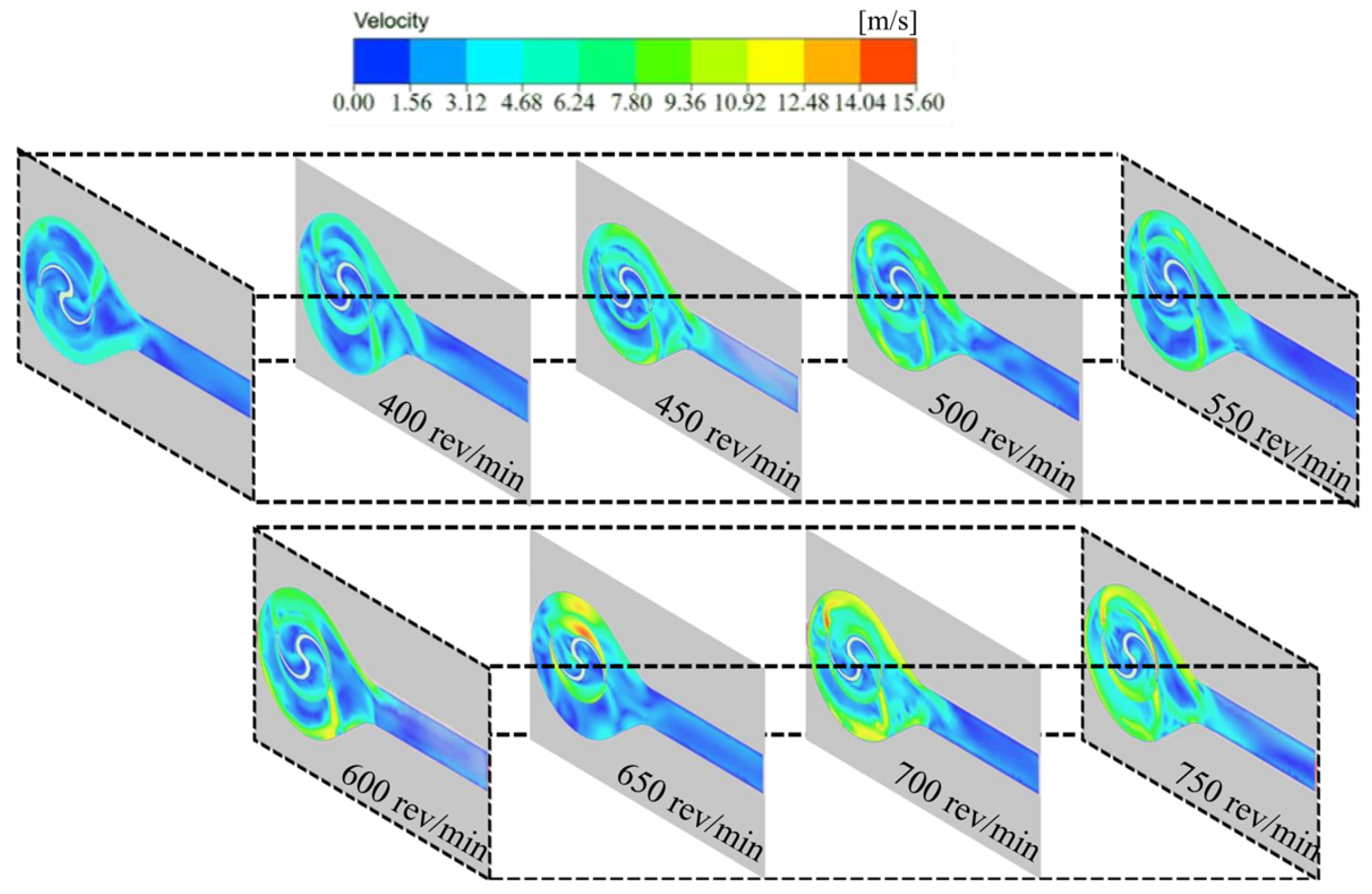
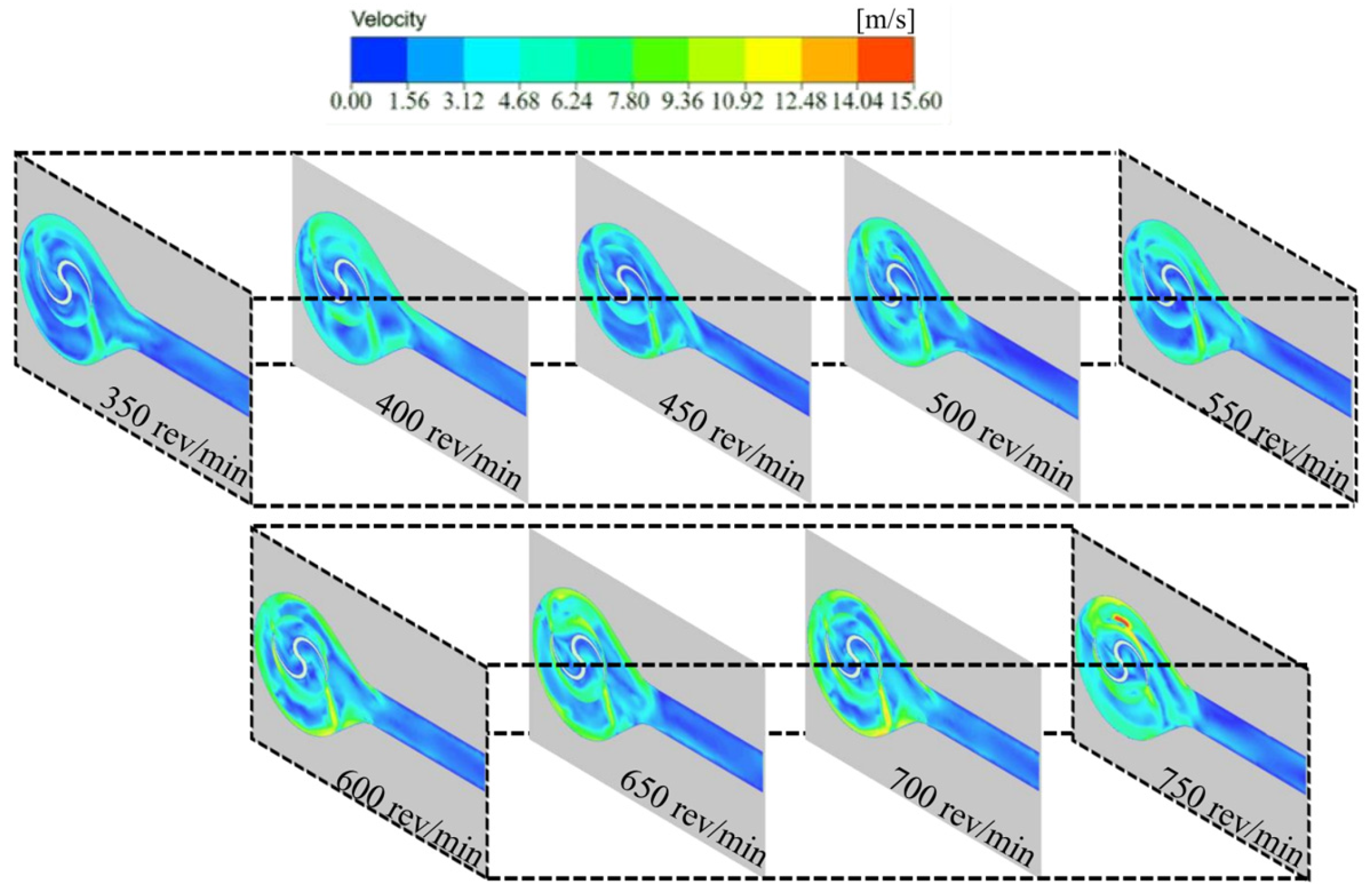
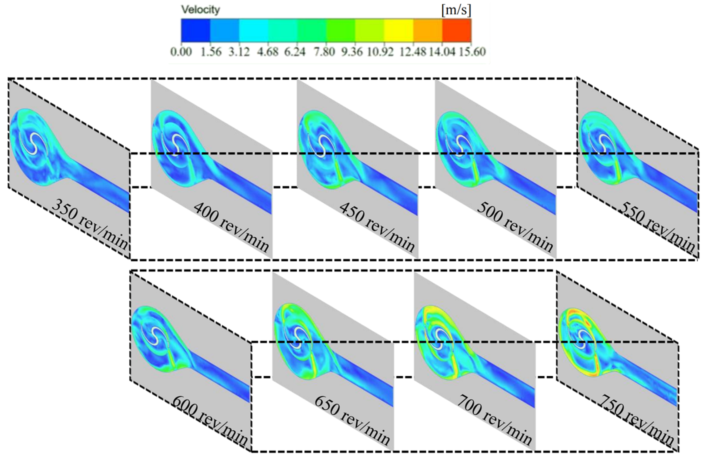
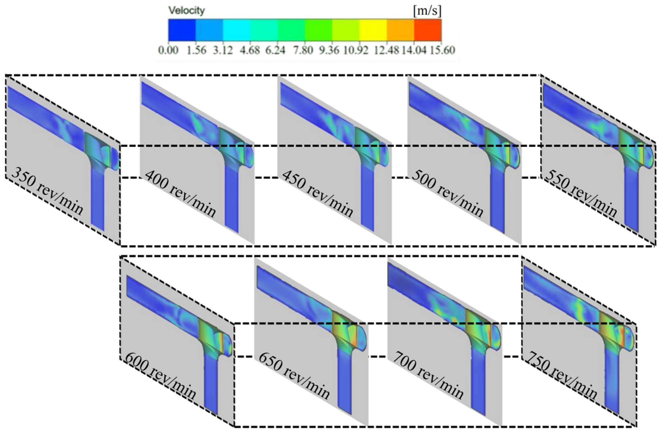
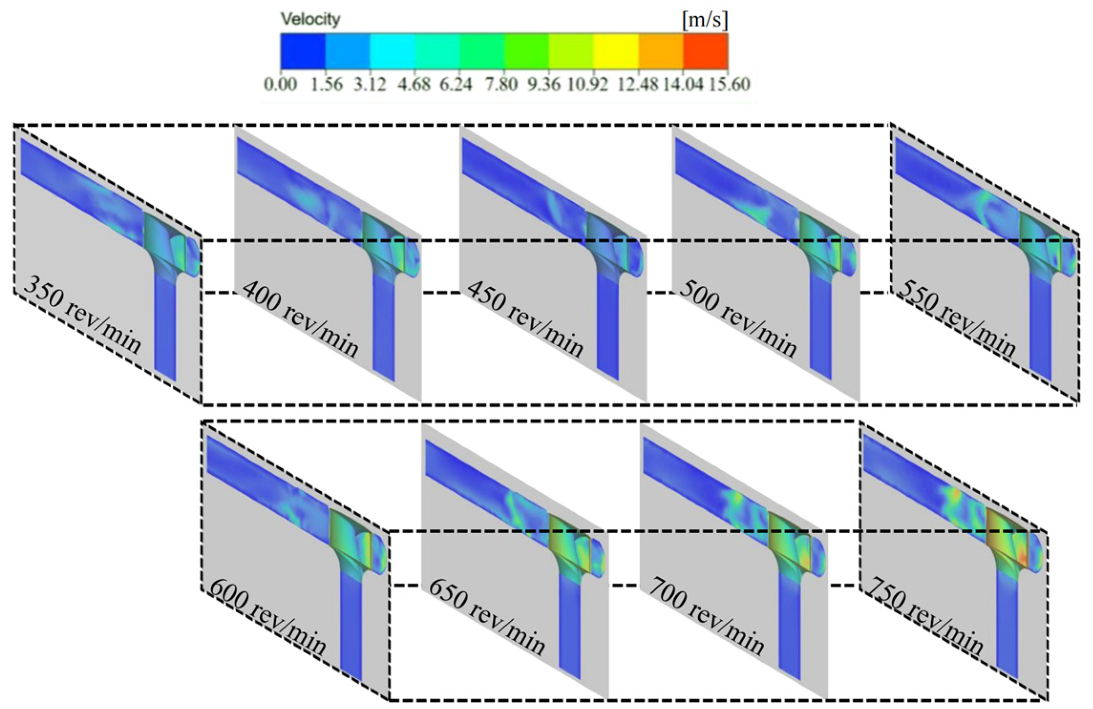
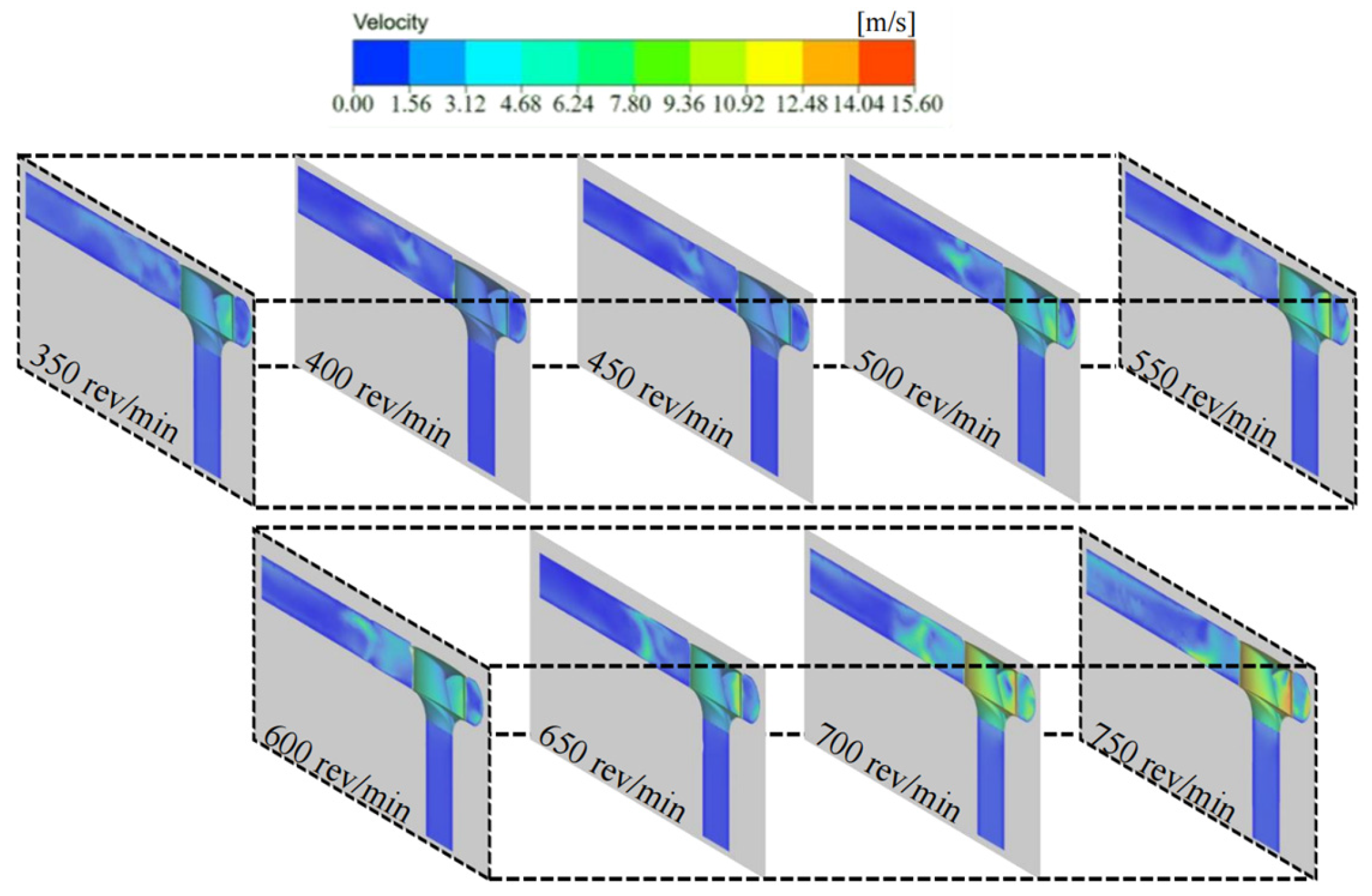
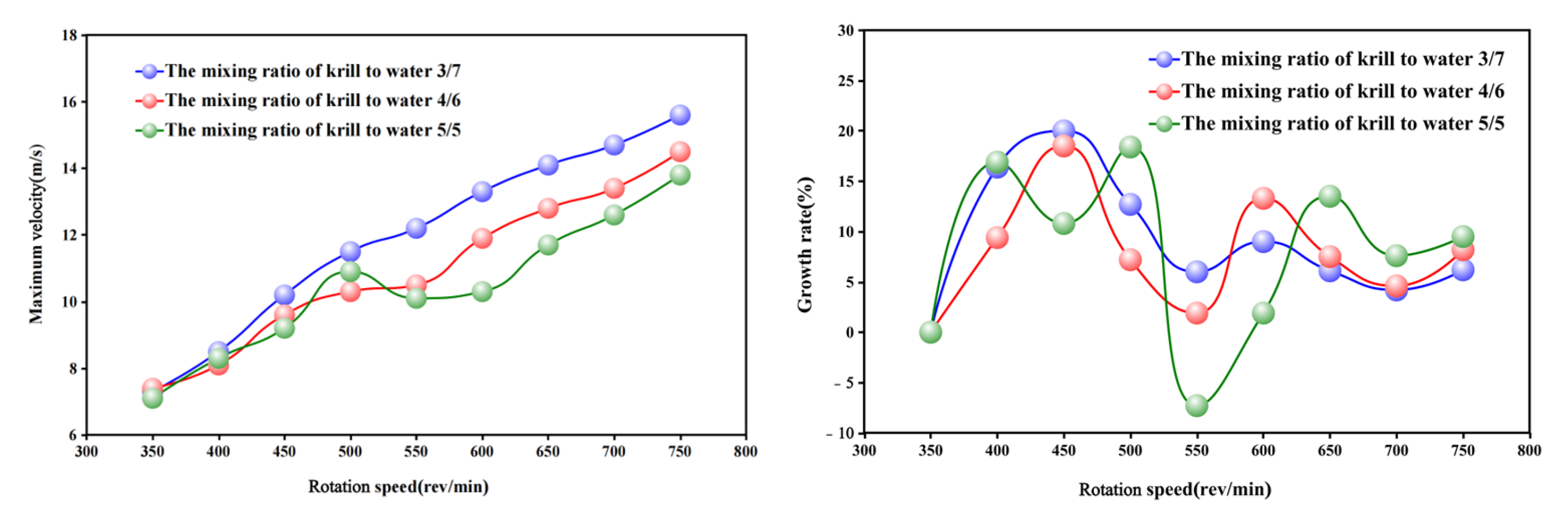
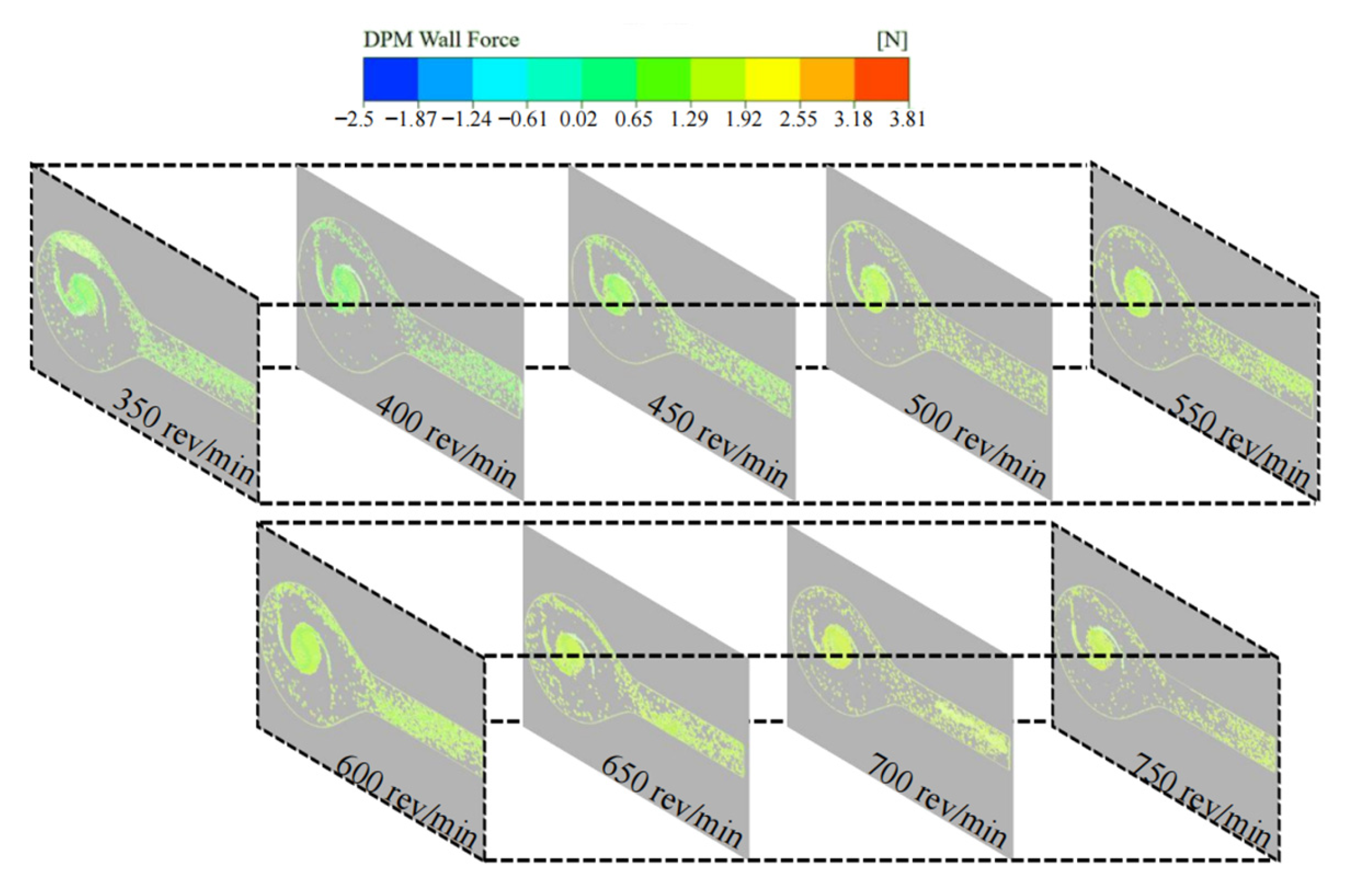
The simulation study demonstrated that when the centrifuge rotation speed was within the range of 550–600 rev/min, the collision between the krill body and the pumping machine wall, as well as the krill body itself, was significantly reduced. This result indicated that this condition resulted in the lowest damage rate. Within this specific range of rotation speeds, the growth rate of the velocity gradient in the centrifugal region exhibits a minimum at each working condition, particularly at 550 rev/min. Additionally, the increase in the particle collision force on the krill body with an increasing rotation speed is marginal, suggesting that this range can effectively balance centrifugal separation efficiency and mechanical damage control.
(2)
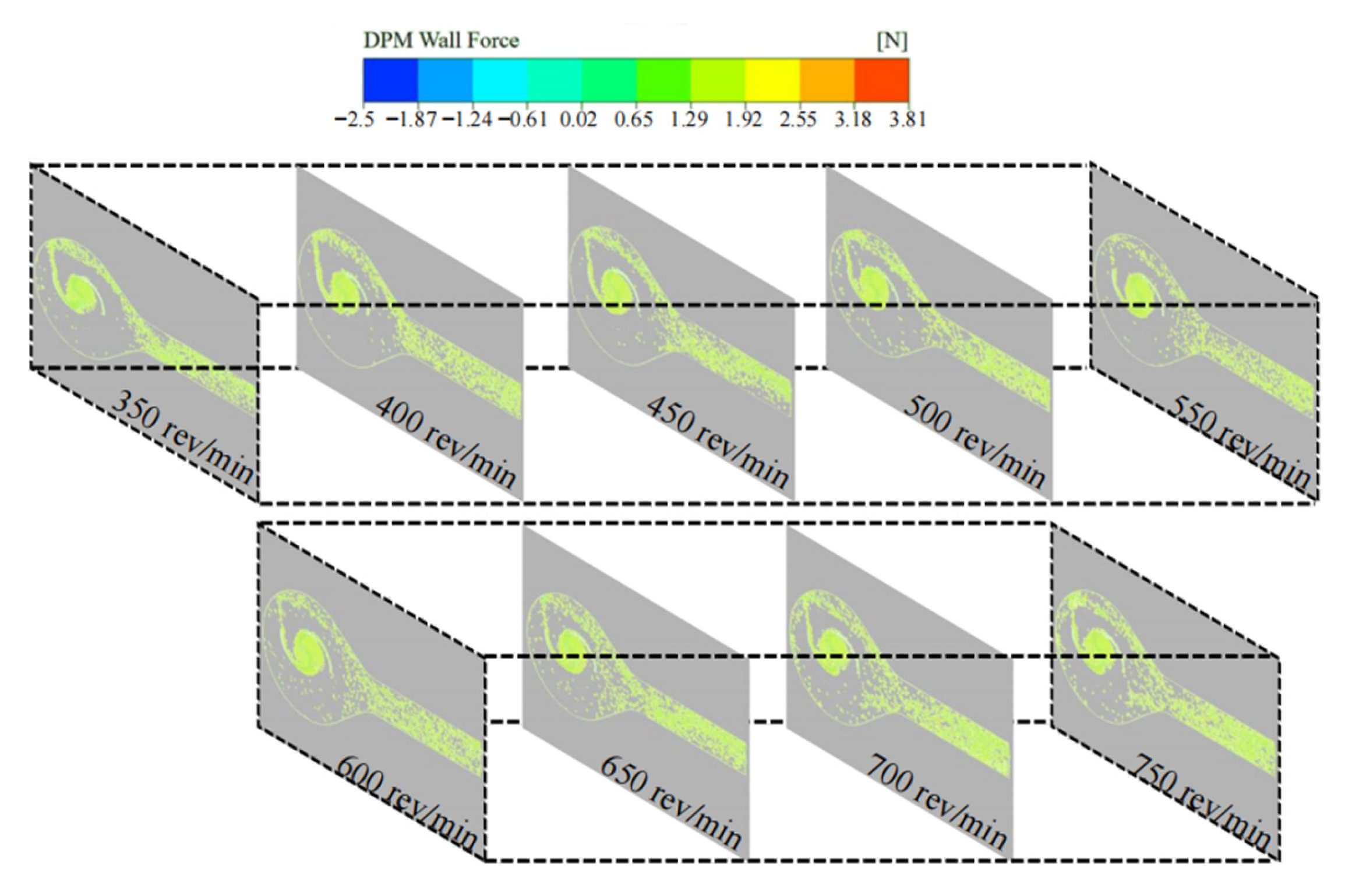
The mixing ratio of krill–water is 4:6, and the centrifuge flow characteristics and krill density are selected to reach the optimal match. This process ensures that the krill body is minimised by the particle collision force and internal extrusion pressure. In this scenario, the propulsion exerted by the water flow on the krill body is found to be less significant than in the 3/7 condition. This, in turn, results in a decrease in the frequency of collisions between the krill body and the inner wall surface of the pumping apparatus. Moreover, in contrast to the 5/5 condition, the decline in krill body density serves to reduce extrusion stress between the groups, thereby conferring a dual benefit in the form of damage inhibition.
(3)
Through the combined analysis of the interaction effect of rotational speed and mixing ratio, it was determined that a combination of 550–600 rev/min and a 4/6 mixing ratio could optimise the velocity distribution of the flow field and the mechanical response of the krill body concurrently. In this condition, the maximum velocity in the centrifuge and the particle collision force on the krill body were both significantly reduced, and the uniformity of the distribution of the particle collision force was improved. In addition, the damage to the krill body was significantly reduced in comparison with the other 25 groups of conditions. This provides a basis for the selection of krill suction pump parameters.

Author Contributions

Conceptualization, Writing—Original Draft, Data Curation, Formal Analysis, P.L.; Investigation, Resources, Software, Writing—Review and Editing, Validation, L.L.; Visualisation, Supervision, Funding Acquisition, Z.X. All authors have read and agreed to the published version of the manuscript.

Funding

This research was supported by the National Key R&D Program of China (2023YFD2401203).

Institutional Review Board Statement

Not applicable.

Informed Consent Statement

Not applicable.

Data Availability Statement

This research data has been presented in current paper.

Acknowledgments

All authors would like to express the sincere thanks to editor and reviewers for valuable comments.

Conflicts of Interest

The authors declare no conflicts of interest.

References

  1. Murphy, E.J.; Cavanagh, R.D.; Drinkwater, K.F.; Grant, S.M.; Heymans, J.J.; Hofmann, E.E.; Hunt, G.L., Jr.; Johnston, N.M. Understanding the structure and functioning of polar pelagic ecosystems to predict the impacts of change. Proc. R. Soc. B 2016, 283, 20161646. [Google Scholar] [CrossRef] [PubMed]
  2. Trathan, P.N.; Hill, S.L. The Importance of Krill Predation in the Southern Ocean. In Biology and Ecology of Antarctic Krill; Springer: Cham, Switzerland, 2016; pp. 321–350. [Google Scholar]
  3. Cavan, E.L.; Belcher, A.; Atkinson, A.; Hill, S.L.; Kawaguchi, S.; McCormack, S.; Meyer, B.; Nicol, S.; Ratnarajah, L.; Schmidt, K.; et al. The importance of Antarctic krill in biogeochemical cycles. Nat. Commun. 2019, 10, 4742. [Google Scholar] [CrossRef] [PubMed]
  4. Schmidt, K.; Atkinson, A.; Steigenberger, S.; Fielding, S.; Lindsay, M.; Pond, D.W.; Tarling, G.; Klevjer, T.A.; Allen, C.S.; Nicol, S.; et al. Seabed foraging by Antarctic krill: Implications for stock assessment, bentho-pelagic coupling, and the vertical transfer of iron. Limnol. Oceanogr. 2011, 56, 1411–1428. [Google Scholar] [CrossRef]
  5. Nicol, S.; Foster, J. The Fishery for Antarctic Krill: Its Current Status and Management Regime. In Biology and Ecology of Antarctic Krill; Springer: Cham, Switzerland, 2016; pp. 387–421. [Google Scholar]
  6. Xie, D.; Gong, M.; Wei, W.; Jin, J.; Wang, X.; Wang, X.; Jin, Q. Antarctic Krill (Euphausia superba) Oil: A Comprehensive Review of Chemical Composition, Extraction Technologies, Health Benefits, and Current Applications. Compr. Rev. Food Sci. Food Saf. 2019, 18, 514–534. [Google Scholar] [CrossRef] [PubMed]
  7. Yin, L.; Jiang, X.; Fan, Y.; Wang, J.; Xue, C.; Xue, Y. Preparation, Gel electrophoresis analysis, and nutritional evaluation of a functional krill protein concentrate with low fluoride level from Antarctic krill (Euphausia superba). J. Aquat. Food Prod. Technol. 2017, 26, 958–968. [Google Scholar] [CrossRef]
  8. Krafft, B.A.; Krag, L.A. Assessment of mortality of Antarctic krill (Euphausia superba) escaping from a trawl. Fish. Res. 2015, 170, 102–105. [Google Scholar] [CrossRef]
  9. Zhang, R.; Chen, X.; Luo, J. Knowledge Mining of Low Specific Speed Centrifugal Pump Impeller Based on Proper Orthogonal Decomposition Method. J. Therm. Sci. 2021, 30, 840–848. [Google Scholar] [CrossRef]
  10. Qian, H.; Mou, J.; Ren, Y.; Zhu, Z.; Liu, N.; Zheng, S.; Wu, D. Investigation of Self-Priming Process of a Centrifugal Pump with Double Blades. J. Therm. Sci. 2021, 30, 849–858. [Google Scholar] [CrossRef]
  11. Li, G.; Zhang, J.; Mao, J.; Yuan, S.; Jia, J. Numerical Investigation of the Transient Flow and Frequency Characteristic in a Centrifugal Pump with Splitter Blades. J. Therm. Sci. 2021, 30, 562–573. [Google Scholar] [CrossRef]
  12. Li, Q.; Li, S.; Wu, P.; Huang, B.; Wu, D. Investigation on Reduction of Pressure Fluctuation for a Double-Suction Centrifugal Pump. Chin. J. Mech. Eng. 2021, 34, 12. [Google Scholar] [CrossRef]
  13. Ou, J.; Jin, D.; Gui, X. Numerical Investigation of the Load Distribution between the Main Blade and the Splitter Blade in a High-Loading Numerical Investigation of the Load Distribution between the Main Blade and the Splitter Blade in a High-Loading Centrifugal Compressor. J. Therm. Sci. 2022, 31, 1682–1695. [Google Scholar] [CrossRef]
  14. Huang, M.; Liu, S.; Qiao, X.; Chen, P.; Liu, Z.; Zhang, X. Simulation study on the drag reduction characteristics of bionic microstructured blades for centrifugal pumps. Surf. Technol. 2023, 52, 196–205. [Google Scholar]
  15. Wu, S.; Zhang, Y.; Zhang, P. Simulation of transient startup process of centrifugal pump. J. Drain. Irrig. Mach. Eng. 2018, 36, 461–465. [Google Scholar]
  16. Sorguven, E.; Incir, S.; Highgate, J. Understanding loss generation mechanisms in a centrifugal pump using large eddy simulation. Int. J. Heat Fluid Flow 2022, 96, 108994. [Google Scholar] [CrossRef]
  17. Xue, X.; Dong, X.; Meng, F.; Li, Z. Numerical simulation analysis of internal flow field and external characteristics of electric submersible centrifugal pump. Comput. Simul. 2024, 41, 120–126. [Google Scholar]
  18. Wei, Y.; Yang, Y.; Zhou, L.; Jiang, L.; Shi, W.; Huang, G. Influence of Impeller Gap Drainage Width on the Performance of Low Specific Speed Centrifugal Pump. J. Mar. Sci. Eng. 2021, 9, 106. [Google Scholar] [CrossRef]
  19. Zhang, H.; You, H.; Lu, H.; Li, K.; Zhang, Z.; Jiang, L. CFD-Rotordynamics Sequential Coupling Simulation Approach for the Flow-Induced Vibration of Rotor System in Centrifugal Pump. Appl. Sci. 2020, 10, 1186. [Google Scholar] [CrossRef]
  20. Blais, B.; Bertrand, O.; Fradette, L.; Bertrand, F. CFD-DEM simulations of early turbulent solid-liquid mixing: Prediction of suspension curve and just-suspended speed. Chem. Eng. Res. Des. 2017, 123, 388–406. [Google Scholar] [CrossRef]
  21. Blais, B.; Bertrand, F. CFD-DEM investigation of viscous solid-liquid mixing: Impact of particle properties and mixer characteristics. Chem. Eng. Res. Des. 2017, 118, 270–285. [Google Scholar] [CrossRef]
  22. Blais, B.; Lassaigne, M.; Goniva, C.; Fradette, L.; Bertrand, F. Development of an unresolved CFD-DEM model for the flow of viscous suspensions and its application to solid-liquid mixing. J. Comput. Phys. 2016, 318, 201–221. [Google Scholar] [CrossRef]
  23. Satish, K.; Gandhi, B.K.; Mohapatra, S.K. Performance characteristics of centrifugal slurry pump with multi-sized particulate bottom and fly ash mixtures. Part. Sci. Technol. 2014, 32, 466–476. [Google Scholar]
  24. Huang, S.; Su, X.H.; Qiu, G.Q. Transient numerical simulation for solid–liquid flow in a centrifugal pump by DEM–CFD Coupling. Eng. Appl. Comput. Fluid Mech. 2015, 9, 411–418. [Google Scholar] [CrossRef]
  25. Beccati, N.; Ferrari, C.; Parma, M.; Semprini, M. Eulerian multi-phase CFD model for predicting the performance of a centrifugal dredge pump. Int. J. Comput. Methods Exp. Meas. 2019, 7, 316–326. [Google Scholar] [CrossRef]
  26. Dong, S.L.; Dong, Y.W.; Huang, L.Y.; Zhou, Y.; Cao, L.; Tian, X.L.; Han, L.M.; Li, D.H. Advancements and hurdles of deeper offshore aquaculture in China. Rev. Aquac. 2024, 16, 644–655. [Google Scholar] [CrossRef]
  27. Huang, Y. History, classification and outlook of fishery equipment in China. China Fish. 2024, 51–55. [Google Scholar]
  28. Xu, J.; Han, L.M.; Zhang, Y. Industrial characteristics of deep-sea aquaculture in China and its policy support. China Fish Econ 2021, 39, 98–107. [Google Scholar]
  29. Yu, J.; Wang, Y. Evolution of deep-sea fisheries policies in China: Review, performance and prospects. Fish. Manag. Ecol. 2023, 30, 109–120. [Google Scholar] [CrossRef]
  30. Guo, X.; Tan, F.C. Analysis of main structure type and application prospect of fish suction pump. Fish. Inf. Strategy 2013, 28, 214–218. [Google Scholar]
  31. Chu, S.; Chen, Z.; Tan, Y.; Liu, P. Research on three-dimensional solid modeling of double runner fish suction pump based on SolidWorks. Fish. Mod. 2018, 45, 55–60. [Google Scholar]
  32. Long, X.; Xu, M.; Wang, J.; Zou, J.; Ji, B. An experimental study of cavitation damage on tissue of Carassius auratus in a jet fish pump. Ocean Eng. 2019, 174, 43–50. [Google Scholar] [CrossRef]
  33. Sui, B.; Feng, Y.; Han, W. A Kind of Net Capsule Fish Suction Technology for Large Pelagic Trawlers. zl201210548872. 2, 10 July 2013. [Google Scholar]
  34. Fang, X.; Mao, W.; Shen, J.; Xu, Z.; Chen, Z.; Wang, Z. Research design and exploration of an Antarctic krill suction pump. Electromech. Equip. 2019, 36, 63–66. [Google Scholar]
  35. Liu, P.; Jiao, E.; Lin, L. Performance analysis of fish suction pumps with different forms of worm casings based on fluid analysis. Mar. Eng. 2020, 42, 72–76. [Google Scholar]
  36. Matsusaka, Japan. Live Fish Transfer Pump [EB/OL]. Available online: http://www.matsusakaltd.co.jp/product.htm (accessed on 10 February 2025).
  37. Mcnabb, C.D.; Liston, C.R.; Borthwick, S.M. Passage of juvenile chinook salmon and other fish species through archimedes lifts and a hydrostat pump at Red Bluff California. Trans. Am. Fish. Soc. 2003, 132, 326–334. [Google Scholar] [CrossRef]
  38. Inventive Marine Products Limited of Canada. CanaVac Fish Pumps [EB/OL]. Available online: https://inventivemarine.com/canavac-fish-pumps (accessed on 18 May 2025).
  39. VAKI. Aquaculture Systems Limited of Iceland: Heathro Fish Pump [EB/OL]. Available online: http://www.seaquest.ie (accessed on 25 January 2025).
  40. Zhang, F. Fluid Mechanics; China Water & Power Press: Beijing, China, 2013. [Google Scholar]
  41. Wang, H. My Understanding of Fluid Mechanics; National Defense Industry Press: Beijing, China, 2014. [Google Scholar]
  42. Schetz, J.A.; Fuhs, A.E. Fundamentals of Fluid Mechanics; John Wiley & Sons: Hoboken, NJ, USA, 1999. [Google Scholar]
  43. Yang, W.; Jin, X.; Gu, M. Research and application of balanced atmospheric boundary layer in numerical simulation of wind engineering. J. Civ. Eng. 2007, 40, 1–5. [Google Scholar]
  44. Kawaguchi, S.; Nicol, S. Learning about Antarctic Krill from the Fishery. Antarct. Sci. 2007, 19, 219–230. [Google Scholar] [CrossRef]
  45. Zhu, W.; Xiong, Z.; He, M. Numerical simulation and optimal design of the flow field in the cargo hold of an Antarctic krill ship. Int. Jt. Conf. Civ. Mar. Eng. 2023, 2023, 334–340. [Google Scholar] [CrossRef]
  46. Pagalthivarthi, K.V.; Gupta, P.K.; Tyagi, V.; Ravi, M.R. CFD Prediction of Erosion Wear in Centrifugal Slurry Pumps for Dilute Slurry Flows. Comput. Multiph. Flows 2011, 50, 52–56. [Google Scholar] [CrossRef]
  47. Zhang, D.; Mei, J.; Zhao, R.; Huang, J.; Jin, Y. Optimized design of fluoroplastic two-phase flow pump based on response surface method. J. Irrig. Drain. Mach. Eng. 2020, 38, 898–903+921. [Google Scholar]
  48. Li, B.; Wang, X.; Li, C.; Liu, H.; Ding, K.; Tan, M. Trajectory and distribution of large particles in a slurry transfer pump. Min. Res. Dev. 2020, 40, 138–144. [Google Scholar]
  49. Shen, Z.J.; Li, R.N.; Han, W.; Zhao, W.G.; Wang, X.H. The research on particle trajectory of solid-liquid two-phase flow and erosion predicting in screw centrifugal pump. IOP Conf. Ser. Mater. Sci. Eng. 2016, 129, 012052. [Google Scholar] [CrossRef]
  50. Huang, L.X.; Kumar, K.; Mujumdar, A.S. A comparative study of a spray dryer with rotary disc atomizer and pressure nozzle using computational fluid dynamic simulations. Chem. Eng. Process. Process Intensif. 2006, 45, 461–470. [Google Scholar] [CrossRef]
  51. Liu, P.; Xu, Z.; Xu, Z. Design of impeller of centrifugal fish suction pump. Fluid Mach. 2016, 50–54. [Google Scholar]
  52. Liang, J.C. Design and Research of a Fish Suction Pump for an Antarctic Krill Fishing Vessel. Ph.D. Thesis, Dalian Ocean University, Dalian, China, 2022. [Google Scholar]
Figure 1. Krill suction pump flow field discrete-phase equivalent model.
Applsci 15 05836 g001
Figure 2. Centrifugal krill suction pump model and meshing.
Applsci 15 05836 g002
Figure 3. Maximum velocity at different meshes of krill–water mixing ratio of 3/7.
Applsci 15 05836 g003
Figure 4. Pressure contour in pump cross section for krill–water mixing ratio of 3/7.
Applsci 15 05836 g004
Figure 5. Velocity contour in pump cross section for krill–water mixing ratio of 3/7.
Applsci 15 05836 g005
Figure 6. Velocity contour in pump cross section for krill–water mixing ratio of 4/6.
Applsci 15 05836 g006
Figure 7. Velocity contour in pump cross section for krill–water mixing ratio of 5/5.
Applsci 15 05836 g007
Figure 8. Longitudinal section of velocity contour in pumps for krill–water mixing ratio of 3/7.
Applsci 15 05836 g008
Figure 9. Longitudinal section of velocity contour in pumps for krill–water mixing ratio of 4/6.
Applsci 15 05836 g009
Figure 10. Longitudinal section of velocity contour in pumps for krill–water mixing ratio of 5/5.
Applsci 15 05836 g010
Figure 11. Maximum velocity in pumps for each working condition.
Applsci 15 05836 g011
Figure 12. DPM wall force contour cross section for krill–water mixing ratio of 3/7.
Applsci 15 05836 g012
Figure 13. DPM wall force contour cross section for krill–water mixing ratio of 4/6.
Applsci 15 05836 g013
Figure 14. DPM wall force contour cross section for krill–water mixing ratio of 5/5.
Applsci 15 05836 g014
Figure 15. Longitudinal section of DPM wall force contour for krill–water mixing ratio of 3/7.
Applsci 15 05836 g015
Figure 16. Longitudinal section of DPM wall force contour for krill–water mixing ratio of 4/6.
Applsci 15 05836 g016
Figure 17. Longitudinal section of DPM wall force contour for krill–water mixing ratio of 5/5.
Applsci 15 05836 g017
Figure 18. Maximum pressure for each operating condition.
Applsci 15 05836 g018
Table 1. The mesh-independent validation statistics.
Mesh TypeTotal ElementsMaximum Velocity/m s−1
A1.2 × 1058.9
B3.6 × 1059.8
C7.2 × 10510.20
D1.4 × 10610.18
E2.1 × 10610.22
Disclaimer/Publisher’s Note: The statements, opinions and data contained in all publications are solely those of the individual author(s) and contributor(s) and not of MDPI and/or the editor(s). MDPI and/or the editor(s) disclaim responsibility for any injury to people or property resulting from any ideas, methods, instructions or products referred to in the content.

