Article

Performance Comparison of Lambertian and Non-Lambertian Drone Visible Light Communications for 6G Aerial Vehicular Networks

1
College of Technology and Data, Yantai Nanshan University, Yantai 265713, China
2
Key Laboratory of Signal Detection and Processing in Xinjiang Uygur Autonomous Region, School of Computer Science and Technology (School of Cyberspace Security), Xinjiang University, Urumqi 830046, China
3
China Mobile Research Institute, Beijing 100053, China
4
Department of Electronic Engineering, Beijing National Research Center for Information Science and Technology, Tsinghua University, Beijing 100084, China
*
Author to whom correspondence should be addressed.
Appl. Sci. 2025, 15(11), 5835; https://doi.org/10.3390/app15115835
Submission received: 8 April 2025 / Revised: 19 May 2025 / Accepted: 20 May 2025 / Published: 22 May 2025

Abstract

:
Increasing reported works identify that drones could and should be sufficiently utilized to work as aerial base stations in the upcoming 6G aerial vehicular networks, for providing emergency communication and flexible coverage. Objectively, light-emitting diode (LED) based lighting devices are ubiquitously integrated into these commercially available drone platforms for the general purposes of illumination and indication. Impresively, for further enhancing and diversifying the wireless air interface capability of the above 6G aerial vehicular networks, the solid-state light emitter, especially LED-based visible light communication (VLC) technologies, is increasingly introduced and explored in the rapidly developing drone communications. However, the emerging investigation dimension of spatial light beam is still waiting for essential research attention for the LED-based drone VLC. Up to now, to the best of our knowledge, almost all LED-based drone VLC schemes are still limited to conventional Lambertian LED beam configuration and objectively reject these technical possibilities and potential value of drone VLC schemes with distinct non-Lambertian LED beam configurations. The core contribution of the study is overcoming the existing limitation of the current rigid Lambertian beam use, and comparatively investigating the performance of drone VLC with non-Lambertian LED beam configurations for future 6G aerial vehicular networks. Objectively, this work opens a novel research dimension and provides a series of valuable research opportunities for the community of drone VLC. Numerical results demonstrate that, for a typical drone VLC scenario, compared with about 6.40 Bits/J/Hz energy efficiency of drone VLC based on the baseline Lambertian LED beam configuration with the same emitted power, up to about 15.64 Bits/J/Hz energy efficiency could be provided by the studied drone VLC with a distinct non-Lambertian LED beam configuration. These results show that the spatial LED beam dimension should be further elaborately explored and utilized to derive more performance improvement of the 6G aerial vehicular networks oriented drone VLC.

1. Introduction

Increasing reported works identify that drones, also known as unmanned aerial vehicles, could and should be sufficiently utilized to work as aerial base stations in the upcoming 6G aerial vehicular networks, especially for providing emergency communication and flexible coverage [1,2,3]. Drone wireless communications are expected to provide flexible wireless access, particularly in situations where the conventional telecommunication infrastructure is not available or damaged [4,5,6]. The mature drone-aided wireless communications work on the conventional radio frequency, where the available spectrum resource is almost exhausted [7,8,9].
Objectively, light-emitting diode (LED) based lighting devices are ubiquitously integrated into these commercially available drone platforms for the general purposes of illumination and indication [10,11,12,13]. Impressively, for further enhancing and diversifying the wireless air interface capability of the above 6G aerial vehicular networks, the LED-based visible light communication (VLC) technologies are increasingly introduced and explored in the rapidly developing drone communications [14,15,16,17,18]. Typically, the authors in [19] propose one framework to optimize the trajectories of VLC-enabled UAVs using a particle swarm optimization (PSO) algorithm, and the superior performance of jointly maximizing the sum-rate and rate fairness of the users and minimizing the power consumption has been shown as well. Moreover, the study in [20] presented a new time scale structure to study the effect of constant acceleration on the coordinated multipoint UAV-enabled VLC networks. In this proposed scheme, a novel machine learning and multi-agent method was utilized to solve this complex problem. For a cross-interface application scenario, the authors in [21] proposed a drone-assisted VLC system that uses LEDs as one downlink transmitter to provide underwater devices with communication services. More recently, the researchers have initiated and reported a series of design and optimization solutions in drone VLC systems, including but not limited to the power consumption minimization [22], energy and user mobility awareness [23], maritime target tracking [24], sum-rate maximization [25], autonomous obstacle avoidance [26], 3-D placement strategy [27], joint deployment and beam-steering optimization [28], heterogeneous networking [29], optimal height of covert communications [30] and drone non-orthogonal multiple access downlinks [31].
Up to now, numerous performance improvements have been reported from the above typical drone VLC studies. But almost all these studies assume that the concerned LED light sources integrated to drone platform follow generalized Lambertian spatial beams [32], which inevitably cannot cover the LED beam diversity including rotational symmetric and rotational asymmetric non-Lambertian beam patterns and also cannot further leverage this potential design degree of freedom [32,33,34]. It should be emphasized that the non-Lambertian LED beam configurations and the related system performance have been studied in many VLC technology branches [35], and mainly include underwater optical communications, non-orthogonal multiple access, channel modeling, and multiple cells planning. The LED beam effects and the potential performance benefits have been separately evaluated and demonstrated in the above 6G-oriented VLC branch directions. Based on the above analysis, it is essential to fill the research gap of the current drone VLC works from the LED beam configuration dimension, so as to tackle the challenging 6G drone communications requirements via differentiated, even flexible light beam configurations.
Motivated by the facts about drone VLC and LED light beam diversity, the 6G aerial vehicular networks-oriented drone VLC with non-Lambertian LED beam configurations is investigated for the first time. Furthermore, the respective achievable rate under distinct non-Lambertian LED beam configurations is evaluated. Simultaneously, the effect of transceiver altitude, coverage radius, and beam azimuth rotation is estimated in order to enhance the coverage and capacity performance of the involved drone VLC systems correspondingly.
The rest of this article is organized as follows: the drone VLC with distinct optical beam configurations is presented in Section 2. Numerical results are presented in Section 3. Finally, Section 4 concludes this paper.

2. Drone Visible Light Communications with Differentiated LED Beams

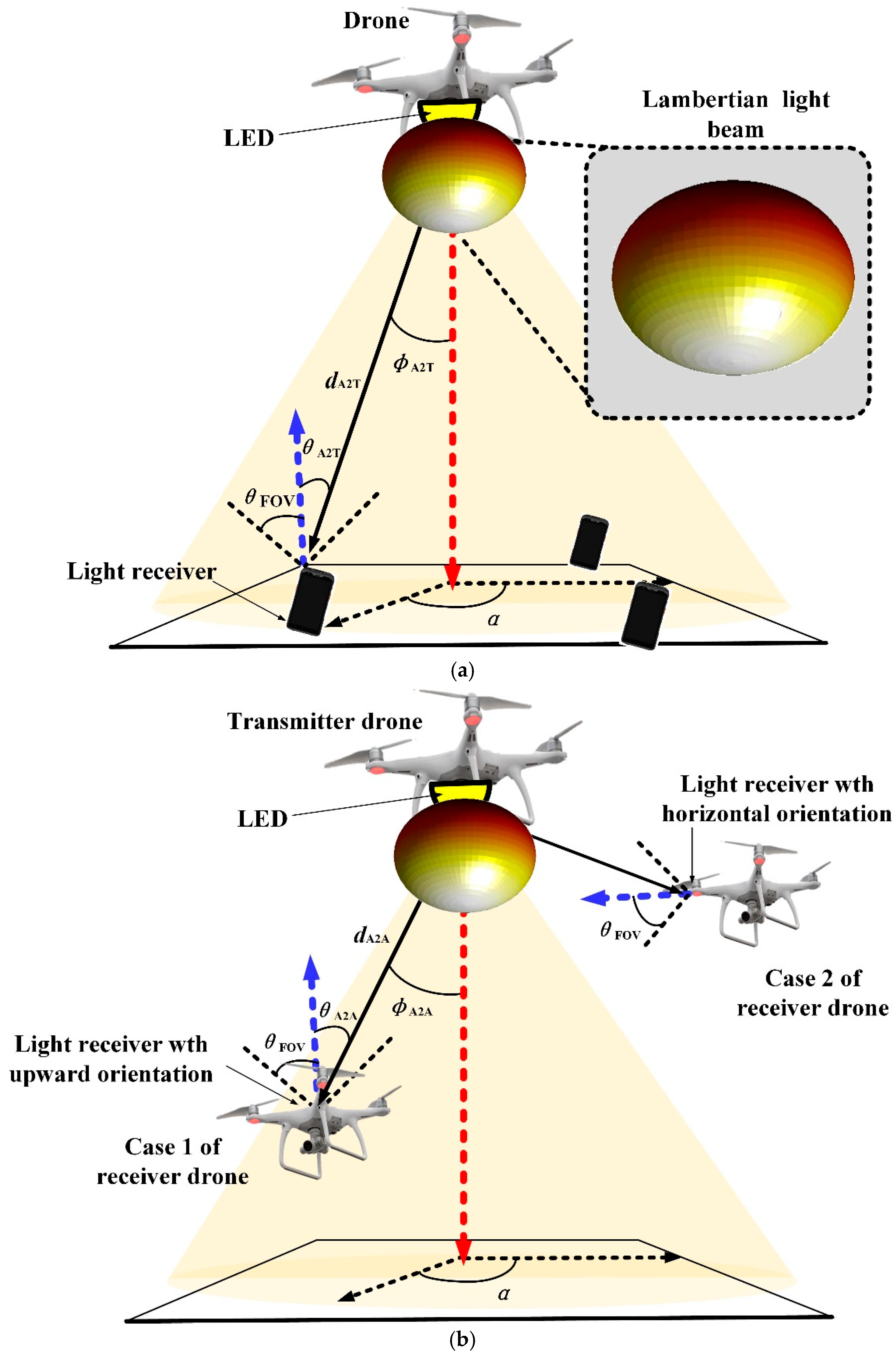
2.1. Drone Visible Light Communications with Lambertian LED Beam

Initially, the general Lambertian LED beam is utilized to configure the drone’s visible light communications. Vitally, radiation intensity is the key metric to measure the spatial radiation characteristics of optical beams. When the LED optical source matches a Lambertian beam, the response radiation intensity R Lam ϕ is given by [32]:
R Lam ϕ = m Lam + 1 2 π cos m Lam ϕ
where ϕ is the irradiance angle from the LED emitter to the light receiver, m Lam denotes the Lambertian order. And m Lam is given by:
m Lam = In 2 In cos ϕ 1 / 2
where ϕ 1 / 2 is the LED semi-angle. And in Figure 1a,b, the application scenario of drone VLC with this baseline LED Beam for terrestrial and aerial users is shown separately.
In a typical drone VLC application scenario of the terrestrial user, the channel gain of the above Lambertian drone VLC H A 2 T Lam is given as [32]:
H A 2 T Lam = A PD d A 2 T 2 R Lam ϕ A 2 T T s θ A 2 T g θ A 2 T cos θ A 2 T ,                   0 θ A 2 T θ FOV 0 ,                                                                                                                                                             θ A 2 T > θ FOV
where A PD denotes the detection area of terrestrial user receiver; d A 2 T denotes the distance between the drone LED and the terrestrial user receiver; ϕ A 2 T denotes the irradiance angle from the optical source to the terrestrial user receiver; θ A 2 T denotes the incident angle to the terrestrial user receiver and θ FOV is the field of view (FOV) of receiver, as shown in Figure 1a. And T s θ A 2 T is the gain of the optical filter and g θ A 2 T is the gain of the optical concentrator, given by [32]:
g θ A 2 T = n 2 sin 2 θ FOV ,                 0 θ A 2 T θ FOV 0 ,                                                     θ A 2 T > θ FOV
where n being the refractive index of the optical concentrator.
When a Lambertian optical beam of a drone with altitude H is applied to configure the aerial to terrestrial (A2T) user link, the A2T geometry relationship of ϕ A 2 T and θ A 2 T could be expressed as:
cos ϕ A 2 T = cos θ A 2 T = H d A 2 T = H r A 2 T 2 + H 2
where r A 2 T being the radial distance between the drone and the terrestrial user on the ground plane.
Therefore, for the A2T link, the Lambertian drone channel gain H A 2 T Lam should be renewed as:
H A 2 T Lam = A T d A 2 T 2 m Lam + 1 2 π cos m Lam ϕ A 2 T T s θ A 2 T n 2 sin 2 θ FOV cos θ A 2 T ,             0 θ A 2 T θ FOV                       0 ,                                                                                                                                                                                                                   θ A 2 T > θ FOV                       = A T d A 2 T 2 m Lam + 1 2 π H r A 2 T 2 + H 2 m Lam + 1 T s θ A 2 T n 2 sin 2 θ FOV ,                     0 θ A 2 T θ FOV                       0 ,                                                                                                                                                                                                                   θ A 2 T > θ FOV ,
On the other hand, when a Lambertian optical beam of the drone and the aerial user with upward orientation receiver is applied to configure the drone aerial to aerial (A2A) user link, the A2A geometry relationship of ϕ A 2 A and θ A 2 A , up could be expressed as:
cos ϕ A 2 A = cos θ A 2 A , up = h A 2 A d A 2 A = H h alt r A 2 A 2 + H h alt 2 ,
where ϕ A 2 A denotes the irradiance angle for the optical source to the aerial user; θ A 2 A , up denotes the incident angle to the aerial user receiver with upward orientation receiver, h alt denotes the altitude of aerial user, and r A 2 A being the radial distance between drone and aerial user on the ground plane, as shown in Figure 1b.
Similarly, by referring (3) and (7), the baseline Lambertian optical channel gain for drone A2A VLC with upward orientation receiver H A 2 A , up Lam could be renewed as:
H A 2 A , up Lam = A T d A 2 A 2 R Lam ϕ A 2 A T s θ A 2 A , up g θ A 2 A , up cos θ A 2 A , up ,               0 θ A 2 A , up θ FOV             0 ,                                                                                                                                                                                           θ A 2 A , up > θ FOV = A T d A 2 A 2 m Lam + 1 2 π cos m Lam ϕ A 2 A T s θ A 2 A , up n 2 sin 2 θ FOV cos θ A 2 A , up ,             0 θ A 2 A , up θ FOV             0 ,                                                                                                                                                                                                                                                 θ A 2 A , up > θ FOV = A T d A 2 A 2 m Lam + 1 2 π H h alt r A 2 A 2 + H h alt 2 m Lam + 1 T s θ A 2 A , up n 2 sin 2 θ FOV ,             0 θ A 2 A , up θ FOV             0 ,                                                                                                                                                                                                                                                             θ A 2 A , up > θ FOV ,
Particularly, when Lambertian optical beam of a drone and the aerial user with a horizontal orientation receiver are applied to configure the drone A2A user link, the A2A geometry relationship of θ A 2 A , hor could be expressed as:
cos θ A 2 A , hor = r A 2 A d A 2 A = r A 2 A r A 2 A 2 + H h alt 2 ,
Similarly, by referring (3) and (9), the baseline Lambertian optical channel gain H A 2 A , hor Lam for drone A2A VLC with horizontal orientation receiver could be renewed as:
H A 2 A , hor Lam = A T d A 2 A 2 R Lam ϕ A 2 A T s θ A 2 A , hor g θ A 2 A , hor cos θ A 2 A , hor , 0 θ A 2 A , hor θ FOV             0 , θ A 2 A , hor > θ FOV = A T T s θ A 2 A d A 2 A 2 m Lam + 1 2 π cos m Lam ϕ A 2 A n 2 sin 2 θ FOV cos θ A 2 A , hor , 0 θ A 2 A , hor θ FOV             0 , θ A 2 A , hor > θ FOV = A T T s θ A 2 A d A 2 A 2 m Lam + 1 2 π H h alt m Lam r A 2 A r A 2 A 2 + H h alt 2 m Lam + 1 n 2 sin 2 θ FOV , 0 θ A 2 A , hor θ FOV               0 , θ A 2 A , hor > θ FOV ,
Accordingly, the achievable rate, i.e., spectral efficiency of baseline Lambertian drone VLC C Lam could be approximately by [19]:
C Lam = 1 2 log 2 1 + e 2 π η P H Lam σ w 2 ,
where η is the PD responsivity in A/W, P refer to the emitted optical signal power and σ w denotes the standard deviation of additive white Gaussian noise. Thus, the relevant energy efficiency η Lam of the baseline Lambertian drone VLC:
η Lam = C Lam P = 1 2 P log 2 1 + e 2 π η P H Lam σ w 2 ,
where H Lam could be explicitly given by (6), (8) and (10) for the Lambertian A2T user link, the Lambertian A2A user link with upward orientation receiver and the Lambertian A2A user link with horizontal orientation receiver, respectively.

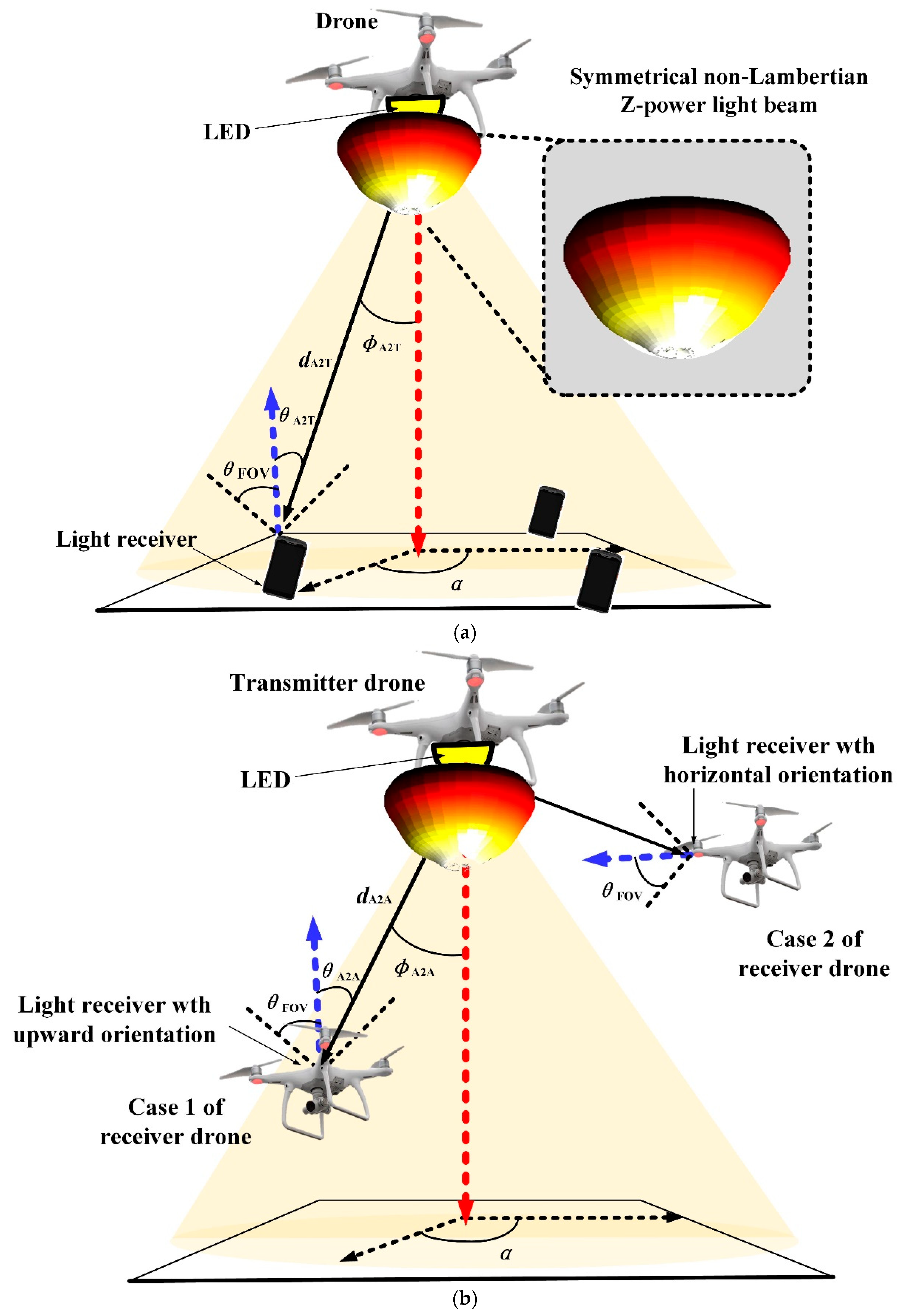
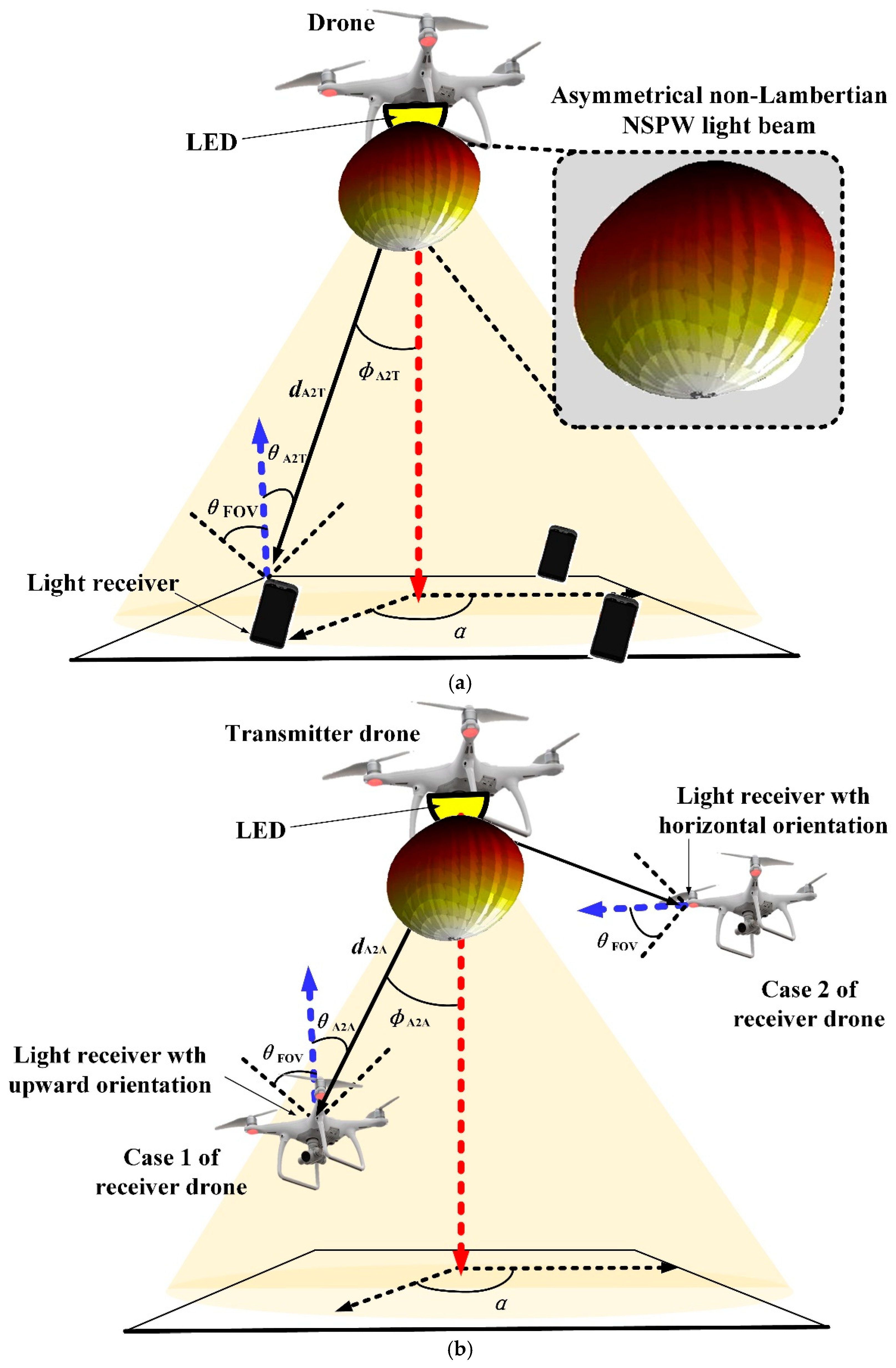
2.2. Drone Visible Light Communications with Non-Lambertian LED Beam

Without loss of generality, for the following discussion of non-Lambertian drone VLC, the beam models from the Z-Power LED and the NSPW345CS Nichia LED are chosen carefully.
In particular, the emission intensity of Z-Power LED beam can be described by the following equation [33,34]:
R Z - Power ϕ = k = 1 K g 1 k Z - Power exp [ ln 2 ( ϕ g 2 k Z - Power g 3 k Z - Power ) 2 ] ,
where K = 3. Additionally, the setting of coefficients g 11 Z - Power , g 21 Z - Power , g 31 Z - Power , g 12 Z - Power , g 22 Z - Power , g 32 Z - Power , g 13 Z - Power , g 23 Z - Power , and g 33 Z - Power are consistent with the work of [33]. And the application scenario of 6G drone VLC based on non-Lambertian Z-Power light beam for terrestrial user and aerial user is shown in Figure 2a and Figure 2b separately.
For drone A2T VLC, the Z-Power channel gain can be presented as:
H A 2 T Z - Power = A PD P normZ - Power d A 2 T 2 R Z - Power ϕ A 2 T T s θ A 2 T g θ A 2 T cos θ A 2 T , 0 θ A 2 T θ FOV             0 , θ A 2 T > θ FOV = k = 1 K g 1 k exp [ ln 2 ( ϕ A 2 T g 2 k Z - Power g 3 k Z - Power ) 2 ] × A PD T s θ A 2 T P normZ - Power d A 2 T 2 n 2 sin 2 θ FOV H r A 2 T 2 + H 2 , 0 θ A 2 T θ FOV             0 , θ A 2 T > θ FOV ,
where P normZ - Power is the power normalization factor for Z-Power LED beam.
Similar to (8), the non-Lambertian Z-Power optical channel gain for A2A VLC with upward orientation receiver could be presented as:
H A 2 A , up Z - Power = A PD P normZ - Power d A 2 A 2 R Z - Power ϕ A 2 A T s θ A 2 A , up g θ A 2 A , up cos θ A 2 A , up , 0 θ A 2 A , up θ FOV             0 , θ A 2 A , up > θ FOV = k = 1 K g 1 k exp [ ln 2 ( ϕ A 2 A g 2 k Z - Power g 3 k Z - Power ) 2 ] × A PD T s θ A 2 A , up P normZ - Power d A 2 A 2 n 2 sin 2 θ FOV H h alt r A 2 A 2 + H h alt 2 , 0 θ A 2 A , up θ FOV             0 , θ A 2 A , up > θ FOV ,
Similar to (10), the non-Lambertian Z-Power optical channel gain for A2A VLC with horizontal orientation receiver could be presented as:
H A 2 A , hor Z - Power = A PD P normZ - Power d A 2 A 2 R Z - Power ϕ A 2 A T s θ A 2 A , hor g θ A 2 A , hor cos θ A 2 A , hor , 0 θ A 2 A , hor θ FOV             0 , θ A 2 A , hor > θ FOV = k = 1 K g 1 k exp [ ln 2 ( ϕ A 2 A g 2 k Z - Power g 3 k Z - Power ) 2 ] × A PD T s θ A 2 A , hor P normZ - Power d A 2 A 2 n 2 sin 2 θ FOV r A 2 A r A 2 A 2 + H h alt 2 , 0 θ A 2 A , hor θ FOV             0 , θ A 2 A , hor > θ FOV ,
Accordingly, similar to (11), the achievable rate of non-Lambertian Z-Power drone VLC could be approximately by [19]:
C Z - Power = 1 2 log 2 1 + e 2 π η P H Z - Power σ w 2 ,
where H Z - Power could be explicitly given by (14)–(16) for the non-Lambertian Z-Power A2T user link, the non-Lambertian Z-Power A2A user link with upward orientation receiver and the non-Lambertian Z-Power A2A user link with horizontal orientation receiver, respectively. Thus, the relevant energy efficiency of the non-Lambertian Z-Power drone VLC:
η Z - Power = C Z - Power P = 1 2 P log 2 1 + e 2 π η P H Z - Power σ w 2 ,
where P refer to the emitted optical signal power as well.
Moreover, as for the case of 6G drone VLC based on asymmetric NSPW light beam, the relevant emission intensity expression can be given [25,26]:
R NSPW ( ϕ , α ) = j = 1 N 2 g 1 j exp In 2 ( ϕ g 2 j ) 2 cos 2 α ( g 3 j ) 2 + sin 2 α ( g 4 j ) 2 ,
where α denotes the azimuth angle from the optical source to the receiver, the coefficient values of Gaussian functions are given as g 11 NSPW = 0.13, g 21 NSPW = 45°, g 31 NSPW = g 41 NSPW = 18°, g 12 NSPW = 1, g 22 NSPW = 0, g 32 NSPW = 38°, and g 42 NSPW = 22° [33]. Similarly, the respective 3D radiation pattern for the drone VLC application scenario of terrestrial user and aerial user is shown in Figure 3a and Figure 3b separately.
Accordingly, the channel gain for non-Lambertian NSPW drone A2T VLC can be written as:
H A 2 T NSPW = A R P normNSPW d A 2 T 2 R NSPW ( ϕ A 2 T , α A 2 T ) T s θ A 2 T g θ A 2 T cos θ A 2 T , 0 θ A 2 T θ FOV             0 , θ A 2 T > θ FOV = A R T s θ A 2 T P normNSPW d A 2 T 2 j = 1 N 2 g 1 j exp In 2 ( ϕ A 2 T g 2 j ) 2 cos 2 α A 2 T ( g 3 j ) 2 + sin 2 α A 2 T ( g 4 j ) 2 × n 2 sin 2 θ FOV H r A 2 T 2 + H 2 ,       0 θ A 2 T θ FOV             0 ,                                                                                                         θ A 2 T > θ FOV
where α A 2 T is the azimuth angle of the terrestrial receiver with respect to the NSPW LED source, P normNSPW is the power normalization factor of the NSPW beam.
For A2A VLC, the non-Lambertian NSPW LED beam-based channel gain with an upward orientation receiver could be presented as:
H A 2 A , up NSPW = A R P normNSPW d A 2 A 2 R NSPW ( ϕ A 2 A , α A 2 A ) T s θ A 2 A , up g θ A 2 A , up cos θ A 2 A , up , 0 θ A 2 A , up θ FOV             0 , θ A 2 A , up > θ FOV = A R T s θ A 2 A , up P normNSPW d A 2 A 2 j = 1 N 2 g 1 j exp In 2 ( ϕ A 2 A g 2 j ) 2 cos 2 α A 2 A ( g 3 j ) 2 + sin 2 α A 2 A ( g 4 j ) 2 × n 2 sin 2 θ FOV H h alt r A 2 A 2 + H h alt 2 ,     0 θ A 2 A , up θ FOV             0 ,                                                                                                                                 θ A 2 A , up > θ FOV
where α A 2 A denotes the azimuth angle from the optical source to the receiver of the aerial user.
Similar to (10), the non-Lambertian NSPW optical channel gain for A2A VLC with horizontal orientation receiver could be presented as:
H A 2 A , hor NSPW = A R P normNSPW d A 2 A 2 R NSPW ( ϕ A 2 A , α A 2 A ) T s θ A 2 A , hor g θ A 2 A , hor cos θ A 2 A , hor , 0 θ A 2 A , hor θ FOV             0 , θ A 2 A , hor > θ FOV = A R T s θ A 2 A , hor P normNSPW d A 2 A 2 j = 1 N 2 g 1 j exp In 2 ( ϕ A 2 A g 2 j ) 2 cos 2 α A 2 A ( g 3 j ) 2 + sin 2 α A 2 A ( g 4 j ) 2 × n 2 sin 2 θ FOV r A 2 A r A 2 A 2 + H h alt 2 ,     0 θ A 2 A , hor θ FOV             0 ,                                                                                                                                   θ A 2 A , hor > θ FOV
Accordingly, similar to (11), the achievable rate of non-Lambertian NSPW drone VLC could be approximately by [19]:
C NSPW = 1 2 log 2 1 + e 2 π η P H NSPW σ w 2 ,
where H Z - Power could be explicitly given by (20)–(22) for the non-Lambertian NSPW A2T user link, the non-Lambertian NSPW A2A user link with upward orientation receiver, and the non-Lambertian NSPW A2A user link with horizontal orientation receiver, respectively. Thus, the relevant energy efficiency of the non-Lambertian NSPW drone VLC:
η NSPW = C NSPW P = 1 2 P log 2 1 + e 2 π η P H NSPW σ w 2 ,
where P refer to the emitted optical signal power of the non-Lambertian NSPW drone VLC as well.
It must be noted that all the optical beam models concerned in this article are based on the international top work of LED radiation pattern, i.e., ref. [33] by I. Moreno, who is one top and well-known researchers of beam patterns of various LEDs, especially including these non-Lambertian ones. Moreover, all the non-Lambertian models in ref. [33] are derived by solid measurements and professional numerical modeling for the commercially available LED, including but not limited to benchmark Lambertian, non-Lambertian Z-Power light beams, and non-Lambertian asymmetric NSPW beams. Therefore, the non-Lambertian model’s accuracy and reliability in this article are solid and supported by sufficient experimental data in ref. [33].
To demonstrate the accuracy of reconstruction, the difference between experimental data and the modeled equation must be compared by computing both the root mean square (RMS) error and the normalized cross correlation (NCC) [33,36,37]. According to the work of [33,36,37], the RMS error between the experiment and the modeled equation can be calculated on a range of M points over the domain, and the reconstructed pattern must be sufficiently accurate, regardless of the type of LED. The RMS error must be less than the standard limit of 5%, and an LED model with an NCC higher than 99% gives enough accuracy for many applications. As for the two non-Lambertian models in our work, the related RMS and NCC for the two models are given in Figure 3f and Figure 1b of the above ref. [33], respectively. Accordingly, as labeled in Figure 3f of the above ref. [33], for Z-Power Side Emitter LED non-Lambertian model from Seoul Semiconductor, the respective RMS error is 0.90% and NCC is 99.84%, which apparently and sufficiently satisfied the above-mentioned standard of RMS and NCC for assuring the accuracy of LED reconstruction model. On the other hand, as shown in Figure 1b of the above ref. [33], the respective RMS error is 1.01% and NCC is 99.97% for the NSPW non-Lambertian model from Nichia, which apparently satisfied the above-mentioned standard of RMS and NCC for assuring the accuracy of the LED reconstruction model as well. Therefore, the accuracy of the applied models has been apparently and sufficiently verified, according to the well-reported work [33].

3. Numerical Results

The performance comparison is made between the drone VLC systems based on the above Lambertian and the non-Lambertian beams in this section, for the terrestrial user and the aerial user. Specifically, one typical medium-size target area, i.e., 5 m × 5 m, is considered for drone-assisted VLC coverage. Additionally, by mainly inheriting from the published drone VLC work of ref. [13], the main simulation parameters are given in Table 1.
In the following numerical analysis of the envisioned drone wireless coverage scenario, one ground corner is set as the origin of coordinates. And the representative center position with coordinates (2.5, 2.5, 0.85) m, the side position with coordinates (2.5, 0.5, 0.85) m, and the corner position with coordinates (0.5, 0.5, 0.85) m are chosen as the candidate terrestrial locations to configure different drone VLC conditions.
Due to the rotational asymmetry described in Figure 3 for the NSPW LED beam, the additional side location 2, i.e., (0.5, 2.5, 0.85) m, is introduced for the following investigation of drone VLC based on the NSPW beam configuration. Similarly, for the aerial user of drone VLC, the two-dimensional coordinates of the aerial side position, the aerial side position 2, and the corner position are (2.5, 0.5) m, (0.5, 2.5) m, and (0.5, 2.5) m, accordingly. Since the envisioned aerial user is based on a drone platform as well, the relevant altitude, i.e., height coordinate for the above aerial receiver positions, could be varied between the height of the terrestrial receiver and the height of the transmitter drone.
Moreover, following the previous system models for the distinct drone VLC systems, both the upward orientation receiver and the horizontal orientation receiver are considered in the investigated aerial user for drone VLC links. For clear comparison and helping readers better understand the differences, the spatial radiation characteristics and application domains of Z-Power and NSPW LED beams are presented in Table 2 as follows:

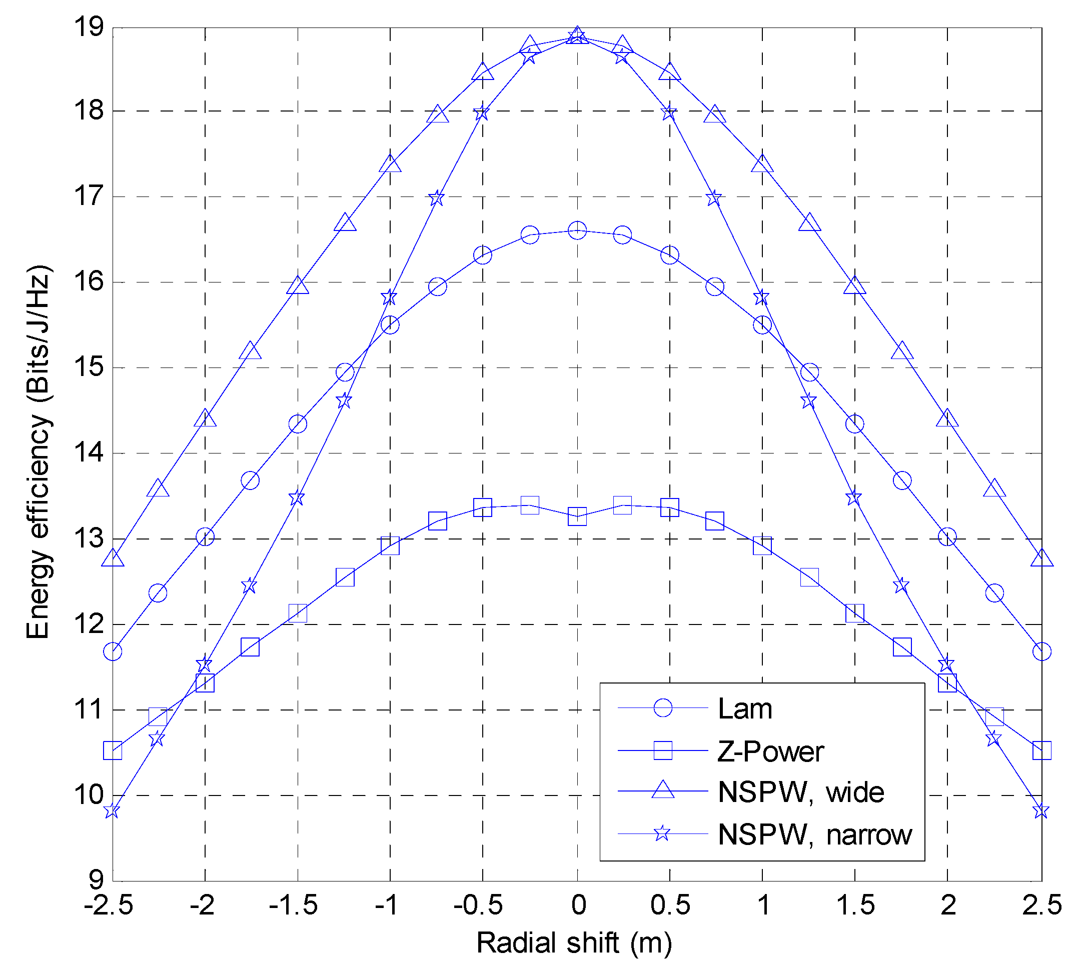
3.1. Effect of Radial Shift

The drone VLC is anticipated to provide continuous wireless coverage for the terrestrial receiver under different radial shift situations. In this subsection, the effect of terrestrial radial displacement on the achievable energy efficiency for drone VLC employing distinct emission beam configurations is evaluated.
Figure 4 compares the energy efficiency performance of drone VLC under different light beam configurations with various radial shifts for the terrestrial user receiver. Since the initial position of the terrestrial receiver is just directly underneath the transmitter drone, the shortest transmission distance and the lowest path loss are faced by the terrestrial receiver. However, with the lateral shift along the radial direction of this terrestrial receiver from the initial center position on the working plane, the link distance is increased, and the relevant path loss is more challenging as well. Accordingly, the key performance metric for drone VLC, i.e., energy efficiency under distinct LED beam configurations, is significantly affected by the radial shift separately.
Numerically, for the case of Lambertian beam configuration-based drone VLC, with the radial shift increased to 2.5 m from the initial center position for the terrestrial receiver, the relevant energy efficiency is reduced to 11.69 Bits/J/Hz from the initial 16.63 Bits/J/Hz. As for the case of non-Lambertian Z-Power light beam configuration-based drone VLC, the relevant energy efficiency is reduced to 10.51 Bits/J/Hz from the initial 13.40 Bits/J/Hz accordingly. Moreover, as for the left case of non-Lambertian NSPW light beam-based drone VLC, since the rotational asymmetric radiation characteristics, both the radial shift along the wide cross section and the narrow cross section of the NSPW light beam should be studied separately. For the mentioned case of radial shift along the wide cross section, the relevant energy efficiency is slowly reduced to the 12.77 Bits/J/Hz from the initial 18.87 Bits/J/Hz when the radial shift is increased to 2.5 m from the initial center position for the terrestrial receiver, thanks to that the more optical signal power could be emitted by the wide radiation cross section to the adverse receiver positions with longer radial shift. However, for the mentioned case of radial shift along the narrow cross section, the relevant energy efficiency is sharply reduced to the 9.80 Bits/J/Hz from the initial 18.87 Bits/J/Hz when the radial shift is increased to 2.5 m from the initial position, due to that the much reduced optical signal power is emitted by the narrow radiation cross section to the adverse receiver positions with longer radial shift. Objectively, for the radial shift in the wide cross section, the non-Lambertian NSPW light beam-based drone VLC presents superior performance, i.e., 1.08 Bits/J/Hz energy efficiency gain compared with the counterpart of the Lambertian beam-based drone VLC.
The above figure of radial shift effect indicates that the case of non-Lambertian Z-Power light beam is the least sensitive to the radial shift of the terrestrial user, while the case of non-Lambertian NSPW light beam is the most sensitive to the radial shift of the terrestrial user. The main reason for these phenomena is the apparent divergence characteristic of the Z-Power light beam and the high directivity characteristic of the NSPW light beam.
To help readers grasp the overall trends and identify key findings of the radial shift effect more effectively, a summary of the results is presented in Table 3 as follows:

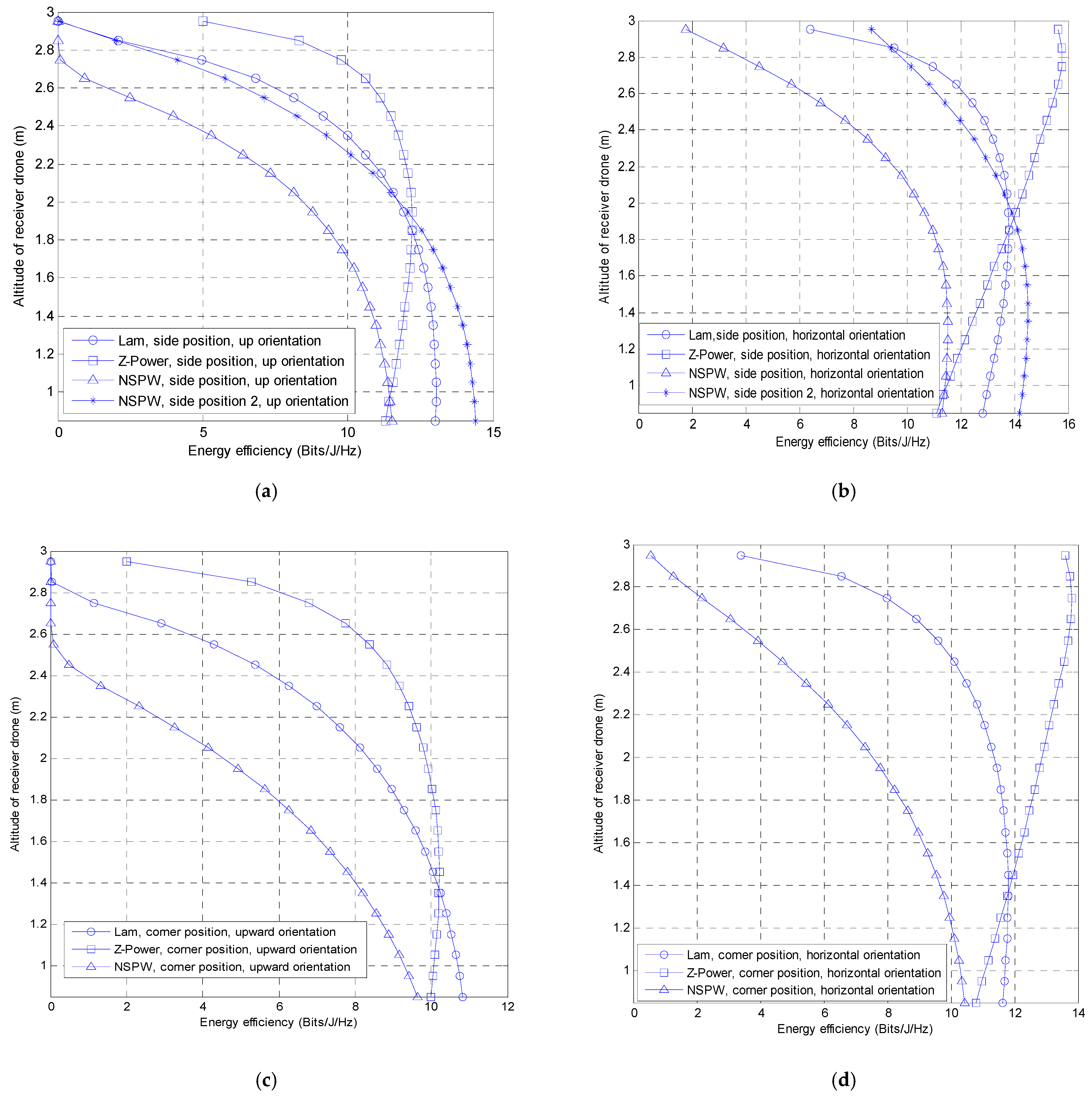
3.2. Effect of Drone Altitude

The drone VLC is anticipated to provide wireless transmission for the aerial receiver at various altitudes. In this subsection, the effect of the altitude of aerial users on the achievable energy efficiency for distinct emission beams-based drone VLC is studied. When the aerial user is located at the side position, as shown in Figure 5a, it can be observed that the energy efficiency at the receiver end under distinct beam configurations is determined by the altitude of the aerial receiver to a different extent. In detail, when the altitude of aerial receiver is increased to 1.95 m from the side position on the ground, the energy efficiency of drone VLC is reduced to 11.92 Bits/J/Hz, 8.80 Bits/J/Hz, and 12.05 Bits/J/Hz from the initial 13.04 Bits/J/Hz, 11.53 Bits/J/Hz, and 14.40 Bits/J/Hz for the Lambertian LED beam, NSPW LED beam (side position), and NSPW LED beam (side position 2), accordingly. On the other hand, the counterpart of the non-Lambertian Z-Power light beam configuration is increased to 12.21 Bits/J/Hz from the initial 11.31 Bits/J/Hz. The above phenomena indicate that a non-Lambertian NSPW light beam (side position 2) provides better performance for near-terrestrial space with an altitude less than 1.95 m, by utilizing its asymmetric spatial radiation capability to cover the more challenging receiver position. In addition, when the altitude of aerial receiver is further increased to 2.95 m from the 1.95 m, the energy efficiency of drone VLC is quickly reduced to 0.002 Bits/J/Hz, 0.00 Bits/J/Hz, and 0.046 Bits/J/Hz from the 11.92 Bits/J/Hz, 8.80 Bits/J/Hz, and 12.05 Bits/J/Hz for the Lambertian light beam configuration, non-Lambertian NSPW light beam configuration (side position), and non-Lambertian NSPW light beam configuration (side position 2), accordingly. And the counterpart of the non-Lambertian Z-Power light beam configuration is gradually reduced to 4.99 Bits/J/Hz from the initial 12.21 Bits/J/Hz, which indicates that Z-Power light beam configuration provides the better performance for non-terrestrial space with altitude higher than 1.95 m, by utilizing its maximum radiation intensity to light the almost horizontal direction, but not the ground as other concerned LED beam configurations in this article. Objectively, at the side position with upward orientation, for the considered maximum altitude of aerial receiver, the non-Lambertian Z-Power light beam-based drone VLC provides 4.988 Bits/J/Hz energy efficiency gain compared with that of the baseline Lambertian beam-based drone VLC.
Similar results could be found when the light receiver with horizontal orientation is adopted for the side position, as shown in Figure 5b. Specifically, when the altitude of aerial receiver is increased to 1.95 m from the side position on the ground, the energy efficiency of drone VLC is changed to 13.78 Bits/J/Hz, 14.07 Bits/J/Hz, 10.66 Bits/J/Hz, and 13.91 Bits/J/Hz from the initial 12.82 Bits/J/Hz, 11.11 Bits/J/Hz, 11.32 Bits/J/Hz, and 14.19 Bits/J/Hz for the Lambertian drone VLC, Z-Power drone VLC, NSPW drone VLC (side position), and NSPW drone VLC (side position 2), accordingly, which verifies that NSPW drone VLC (side position 2) still provides the relative more acceptable performance for near terrestrial space with altitude less than 1.95 m.
In addition, when the altitude of aerial receiver is further increased to 2.95 m from the 1.95 m, the energy efficiency of drone VLC is quickly reduced to 6.40 Bits/J/Hz, 1.76 Bits/J/Hz, and 8.68 Bits/J/Hz from the 13.78 Bits/J/Hz, 10.66 Bits/J/Hz, and 13.91 Bits/J/Hz for the Lambertian light beam configuration, NSPW drone VLC (side position), and NSPW drone VLC (side position 2), accordingly while the counterpart of Z-Power drone VLC is further enhanced to 15.64 Bits/J/Hz, which proves the tremendous superiority of the non-Lambertian Z-Power light beam configuration for the non-terrestrial space with higher altitude, by straightforwardly utilizing its almost maximized omnidirectional horizontal radiation pattern. Particularly, at the side position with horizontal orientation, for the considered maximum altitude of aerial receiver, the non-Lambertian Z-Power light beam-based drone VLC provides 9.24 Bits/J/Hz energy efficiency gain compared with that of the baseline Lambertian beam-based drone VLC. The above numerical results show that compared with the previous upward orientation setting, the horizontal orientation setting of the aerial light receiver could further amplify the unique superiority of the non-Lambertian Z-Power light beam-based drone VLC in higher non-terrestrial space.
Actually, the unique superiority of the non-Lambertian Z-Power light beam is robust in harsher corner positions for the aerial receiver, as shown in Figure 5c of upward orientation and Figure 5d of horizontal orientation. As for the case of upward orientation, once the altitude of the aerial receiver is increased from 1.35 m to the maximum height, the energy efficiency of drone VLC is accordingly reduced to 0.00 Bits/J/Hz, 2.00 Bits/J/Hz, and 0.00 Bits/J/Hz from the 10.24 Bits/J/Hz, 10.21 Bits/J/Hz, and 8.21 Bits/J/Hz for the Lambertian drone VLC, Z-Power drone VLC, and NSPW drone VLC, which illustrates that up to 2.00 Bits/J/Hz energy efficiency gain can be achieved by the Z-Power drone VLC compared with the that of the Lambertian drone VLC, for the considered maximum altitude. Moreover, for the case of horizontal orientation, when the aerial receiver altitude is increased from 1.35 m to the maximum height, the energy efficiency of drone VLC is accordingly changed to 3.40 Bits/J/Hz, 13.60 Bits/J/Hz, and 0.55 Bits/J/Hz from the 11.80 Bits/J/Hz, 11.76 Bits/J/Hz, and 9.77 Bits/J/Hz for the Lambertian drone VLC, Z-Power drone VLC, and NSPW drone VLC, which surprisingly illustrates that for the considered maximum altitude of aerial receiver, compared with the baseline Lambertian drone VLC, up to 10.20 Bits/J/Hz energy efficiency gain could still be achieved by the Z-Power light beam configuration.
The above figures of drone altitude effect indicate that the case of non-Lambertian Z-Power light beam provides the best performance consistency, especially for high altitude domains, while the cases of Lambertian beam and non-Lambertian NSPW light beam illustrate more obvious performance fluctuations with higher altitude. The main reason for these phenomena is that the non-Lambertian Z-Power light beam emits the maximum radiation power in all directions close to horizontal, which, to a large extent, illuminates the whole space domain of the drone VLC. On the other hand, both Lambertian beam and non-Lambertian NSPW light beam emit the maximum radiation power downwards towards the ground, which objectively limits the provision of sufficient lighting to the space domain of the drone VLC.
For helToeaders grasp the overall trends and identify key findings of the drone altitude effect more effectively, a summary of the results is presented in Table 4 as follows:

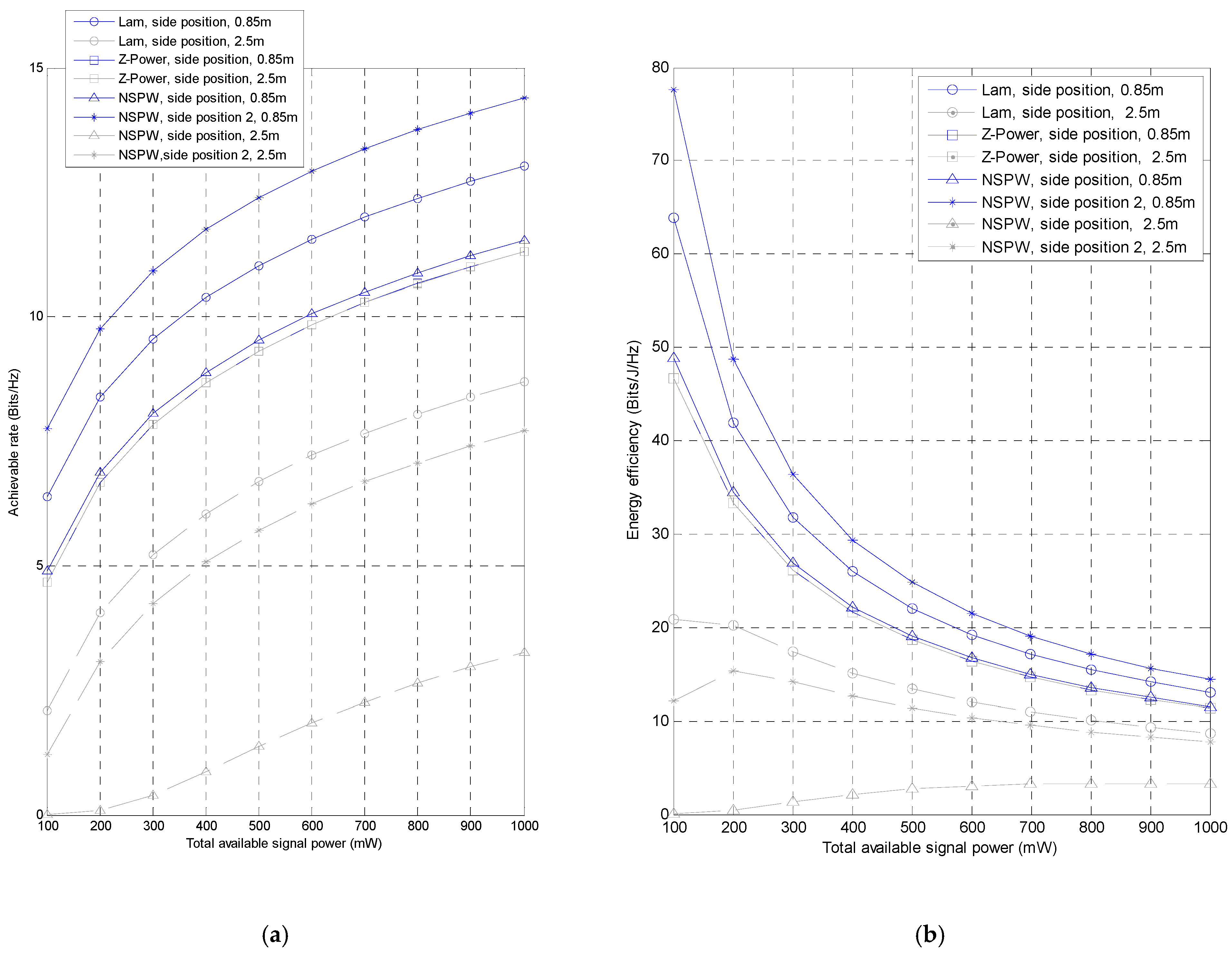
3.3. Effect of Available Emitted Power

Considering that VLC performance highly depends on the power budget at the transmitter, the effect of available signal power on the performance for distinct emission beams-based drone VLC is evaluated for the representative side position of the receiver in this subsection. Generally speaking, the achievable rate of drone VLC under different light beam configurations is enhanced to some extent separately, as shown in Figure 6a. Particularly, for the situation of receiver altitude of 0.85 m, in other word, the receiver is located on the working plane of terrestrial receiver, the achievable rate performance of baseline Lambertian light beam configuration based drone VLC is enhanced to 13.03 Bits/Hz from the initial 6.38 Bits/Hz, when the total available signal power at the transmitter of drone VLC is increased to 1000 mW from the initial 100 mW. At the same time, the achievable rate performance metric is enhanced to 11.31 Bits/Hz, 11.53 Bits/Hz, and 14.40 Bits/Hz, from the initial 4.67 Bits/Hz, 4.89 Bits/Hz, and 7.76 Bits/Hz for the non-Lambertian Z-Power drone VLC, NSPW drone VLC (side position), and NSPW drone VLC (side position 2), respectively. It indicates that compared with the baseline Lambertian drone VLC, the achievable rate gain achieved by the NSPW drone VLC (side position 2) is varied to 1.37 Bits/Hz from the initial 1.38 Bits/Hz, when the total available signal power at the transmitter of drone VLC is increased to 1000 mW from the initial 100 mW, since the more intensive radiation is successfully projected to the side position 2 by the distinct asymmetric spatial emission characteristic of the non-Lambertian NSPW light beam.
Similarly, for the situation of receiver altitude of 2.5 m, in other words, the receiver is located on the typical height of aerial receiver, the achievable rate performance of baseline Lambertian light beam configuration-based drone VLC is enhanced to 8.69 Bits/Hz from the initial 2.09 Bits/Hz, when the total available signal power at the transmitter of drone VLC is increased to 1000 mW from the initial 100 mW. Simultaneously, the achievable rate performance metric is enhanced to 11.31 Bits/Hz, 3.27 Bits/Hz, and 7.71 Bits/Hz, from the initial 4.67 Bits/Hz, 0.0066 Bits/Hz, and 1.22 Bits/Hz for the Z-Power drone VLC, NSPW drone VLC (side position), and NSPW drone VLC (side position 2), accordingly. When the available signal power is increased to 1000 mW from the initial 100 mW, the achievable rate gain provided by the Z-Power beam drone VLC is varied to 2.62 Bits/Hz from the initial 2.58 Bits/Hz, compared with the Lambertian drone VLC, since the unique emission characteristic of Z-Power light beam is capable of radiating more signal power to the non-terrestrial space where the aerial receiver is located. Note that, in Figure 6a, the curves of 0.85 m and 2.5 m for the Z-Power light beam are highly overlapped, which indicates that excellent coverage consistency could be provided by the Z-Power light beam-based drone VLC for the terrestrial light receiver and the aerial light receiver.
On one hand, the energy efficiency of drone VLC under different light beam configurations is degraded to some extent separately, as shown in Figure 6b. Particularly, for the situation of receiver altitude of 0.85 m, the energy efficiency performance of baseline Lambertian light beam configuration based drone VLC is degraded to 13.03 Bits/J/Hz from the initial 63.83 Bits/J/Hz, when the total available signal power at the transmitter of drone VLC is increased to 1000 mW from the initial 100 mW. At the same time, the energy efficiency performance metric is reduced to 11.31 Bits/J/Hz, 11.53 Bits/J/Hz, and 14.40 Bits/J/Hz, from the initial 46.71 Bits/J/Hz, 48.86 Bits/J/Hz, and 77.56 Bits/J/Hz for the non-Lambertian Z-Power light beam configuration, non-Lambertian NSPW light beam (side position), and non-Lambertian NSPW light beam (side position 2), accordingly. This means that compared with the baseline Lambertian configuration-based drone VLC, the energy efficiency gain provided by the non-Lambertian NSPW beam-based drone VLC (side position 2) is varied to 1.37 Bits/J/Hz from the initial 13.73 Bits/J/Hz, when the total available signal power is increased to 1000 mW from the initial 100 mW.
As for the situation of receiver altitude of 2.5 m, the energy efficiency performance of baseline Lambertian configuration-based drone VLC is degraded to 8.69 Bits/J/Hz from the initial 20.89 Bits/J/Hz, when the total available signal power of drone VLC is increased to 1000 mW from the initial 100 mW. Simultaneously, the energy efficiency performance metric is reduced to 11.31 Bits/J/Hz, 0.066 Bits/J/Hz, and 7.71 Bits/J/Hz, from the initial 46.67 Bits/J/Hz, 3.27 Bits/J/Hz, and 12.16 Bits/J/Hz for the non-Lambertian Z-Power light beam configuration, non-Lambertian NSPW light beam (side position), and non-Lambertian NSPW light beam (side position 2), accordingly. This demonstrates that compared with the Lambertian configuration-based drone VLC, the energy efficiency gain provided by the non-Lambertian Z-Power beam-based drone VLC varied to 2.62 Bits/Hz from the initial 25.78 Bits/Hz, when the available signal power is increased to 1000 mW from the initial 100 mW.
The above figures of the emitted power effect indicate that with the increase in the total available signal power, the growth rate of the achievable rate is slowed down, and the energy efficiency performance is accordingly degraded. Note that under different altitudes, the best performance consistency could still be provided by the Z-Power non-Lambertian drone VLC, thanks to its superior performance in lighting the different domains simultaneously.
To help readers grasp the overall trends and identify key findings of the emitted power effect more effectively, a summary of the results is presented in Table 5 as follows:

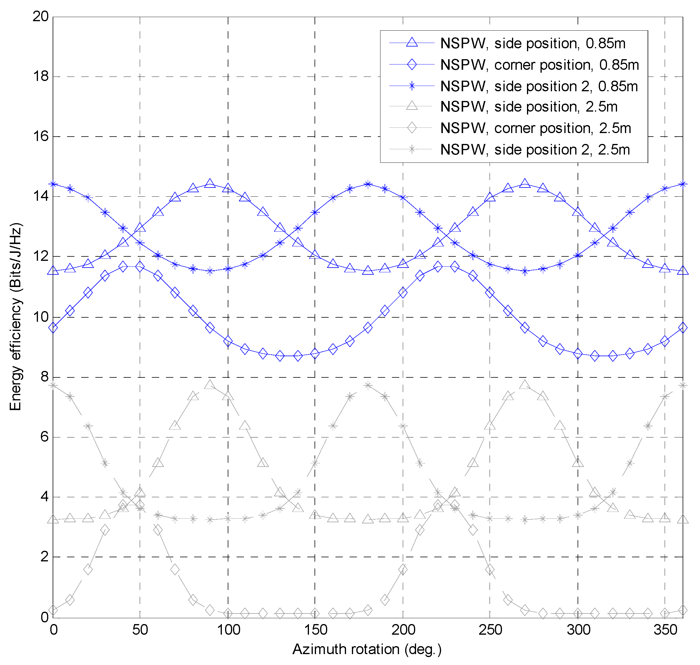
3.4. Effect of Drone Azimuth Rotation

The influence of drone azimuth rotation on the drone VLC is of great significance to be investigated. As for the NSPW drone VLC, as shown in Figure 7, it could be observed that the periodicity in energy efficiency performance is 180° in rotation angle cycle for the concerned positions of the terrestrial user, and the fluctuating energy efficiency performance appears under the same azimuth rotation angle of the NSPW drone.
Specifically, for the side position and the side position 2 of terrestrial users, up to 2.87 Bits/J/Hz energy efficiency fluctuation can be achieved by leveraging of drone azimuth rotation angle. For the terrestrial side position 2, the maximum energy efficiency of 14.40 Bits/J/Hz is achieved with the 0° drone azimuth rotation, while for the terrestrial side position, the minimum achievable rate of 11.53 Bits/J/Hz is achieved with the same drone azimuth rotation. And the maximum energy efficiency of 14.40 Bits/J/Hz is achieved for the terrestrial side position, when the drone azimuth rotation is varied to about 90°. As for the corner position, once the drone azimuth rotation is up to about 50°, the relevant maximum energy efficiency of 11.67 Bits/J/Hz is achieved.
As for the situation of 2.5 m receiver altitude, the homologous periodicity in energy efficiency performance can be identified with the various drone azimuth rotations for the different aerial positions. Note that the rotation angle cycle is also 180° for the concerned three positions of the aerial user; diverse energy efficiency performances appear under the same azimuth rotation angle of the transmitter drone.
The above figures of azimuth rotation effect indicate that the link performance of NSPW non-Lambertian drone VLC is highly relevant to the azimuth rotation angle of the involved drone, especially for the side position and corner position of the VLC receiver. The main reason for these phenomena is that the rotational asymmetry radiation characteristic of this distinct non-Lambertian beam. Objectively, these phenomena provide a novel potential solution to selectively enhance the coverage performance for users in a certain azimuth direction.
To help readers grasp the overall trends and identify key findings of the azimuth rotation effect more effectively, a summary of the results is presented in Table 6 as follows:
It must be noted that this work focuses on the low-altitude scenarios for LED-based drone visible light communications, where the involved drone is near the ground. Typically, these low-altitude scenarios include, but are not limited to, emergency communication, safe-protection, intelligent transportation, indoors, tunnels, and others. Therefore, the link distance between the drone and the user is quite short and less than several meters. Unlike the laser diode-based drone free space optic links for long-range transmission, the studied LED-based drone visible light communications for very short-range connection is less susceptible to the influence of external disturbance, especially atmospheric turbulence. As future work, we plan to extend the link range to tens of meters, even several hundred meters, to investigate the link performance and robustness of LED-based drone visible light communications under distinct atmospheric turbulence conditions.

4. Conclusions

Since the Lambertian drone VLC paradigm cannot characterize the performance of these potential non-Lambertian LED beam-based drone VLC systems, in this work, the non-Lambertian LED beam-based drone VLC wireless links are studied for the first time. For the typical drone communication scenario with equal emitted power budget, compared with the 8.69 Bits/Hz performance of Lambertian drone VLC, up to 2.62 Bits/Hz gain could be achieved by the proposed non-Lambertian LED beam-based drone VLC. Objectively, the above work presents new research opportunities for 6G aerial vehicular networks. In the near future, the exploration of non-Lambertian LED beam-based drone VLC will be extended to the relevant power resource allocation, 3-D deployment, hybrid radio frequency transmission, and other enabling technique solutions. It must be noted that this work is simulation-based and objectively paves the fundamental and essential way for future real-world prototype experiments or the multi-drone systems for this novel non-Lambertian drone visible light communications. The practical challenges and research opportunities of implementing non-Lambertian beams on drones include, but are not limited to, (1) achieving conformal integration of non-Lambertian LED beams with the drone platform, (2) reducing the weight effect of the non-Lambertian LED with a customized lens, and (3) optimizing and controlling the power consumption of diverse non-Lambertian LED-based drone VLC.

Author Contributions

J.D., Determine the theme and structure of the article, provide professional knowledge in the field of visible light communications, write and modify the article, and reply to comments from editors and reviewers; C.-L.I., Provide theoretical knowledge of mobile communication and wireless communication; J.W., Looking for the literature, participate in the discussion and writing some of the content; H.Y., Looking for the literature, participate in the discussion. All authors have read and agreed to the published version of the manuscript.

Funding

This work was supported in part by the National Natural Science Foundation of China (Grants No. 62061043), Yantai Nanshan University Research and Development Fund Project (Grants No. 2025KJ01001), Tianshan Cedar Project of Xinjiang Uygur Autonomous Region (Grants No. 2020XS27), and High-level Talents Introduction Project in Autonomous Region (Grants No. 042419004).

Institutional Review Board Statement

Not applicable.

Informed Consent Statement

Not applicable.

Data Availability Statement

Data are contained within the article.

Conflicts of Interest

Author Chih-Lin I was employed by the company China Mobile Research Institute. The remaining authors declare that the research was conducted in the absence of any commercial or financial relationships that could be construed as a potential conflict of interest.

References

  1. Wu, M.; Guo, K.; Li, X.; Nauman, A.; An, K.; Wang, J. Optimization Design in RIS-Assisted Integrated Satellite-UAV-Served 6G IoT: A Deep Reinforcement Learning Approach. IEEE Internet Things Mag. 2024, 7, 12–18. [Google Scholar] [CrossRef]
  2. Feng, W.; Wang, Y.; Chen, Y.; Ge, N.; Wang, C.X. Structured Satellite-UAV-Terrestrial Networks for 6G Internet of Things. IEEE Netw. 2024, 38, 48–54. [Google Scholar] [CrossRef]
  3. Mozaffari, M.; Lin, X.; Hayes, S. What Will the Future of UAV Cellular Communications Be? A Flight from 5G to 6G. IEEE Commun. Mag. 2021, 59, 74–80. [Google Scholar] [CrossRef]
  4. Geraci, G.; Garcia-Rodriguez, A.; Azari, M.M.; Lozano, A.; Mezzavilla, M.; Chatzinotas, S.; Chen, Y.; Rangan, S.; Di Renzo, M. What Will the Future of UAV Cellular Communications Be? A Flight From 5G to 6G. IEEE Commun. Surv. Tutor. 2022, 24, 1304–1335. [Google Scholar] [CrossRef]
  5. McEnroe, P.; Wang, S.; Liyanage, M. A Survey on the Convergence of Edge Computing and AI for UAVs: Opportunities and Challenges. IEEE Internet Things J. 2022, 9, 15435–15459. [Google Scholar] [CrossRef]
  6. Huda, S.A.; Moh, S. Survey on computation offloading in UAV-enabled mobile edge computing. J. Netw. Comput. Appl. 2022, 201, 103341. [Google Scholar] [CrossRef]
  7. Sun, S.; Wang, T.; Yang, F.; Song, J.; Han, Z. Intelligent reflecting surface-aided visible light communications: Potentials and challenges. IEEE Veh. Technol. Mag. 2022, 17, 47–56. [Google Scholar] [CrossRef]
  8. Wang, T.; Yang, F.; Song, J.; Han, Z. Dimming Techniques of Visible Light Communications for Human-Centric Illumination Networks: State-of-the-Art, Challenges, and Trends. IEEE Wirel. Commun. 2020, 27, 88–95. [Google Scholar] [CrossRef]
  9. Hamza, A.S.; Deogun, J.S.; Alexander, D.R. Classification framework for free space optical communication links and systems. IEEE Commun. Surv. Tutor. 2019, 21, 1346–1382. [Google Scholar] [CrossRef]
  10. Eltokhey, M.W.; Khalighi, M.-A.; Ghassemlooy, Z. UAV Location Optimization in MISO ZF Pre-Coded VLC Networks. IEEE Wirel. Commun. Lett. 2022, 11, 28–32. [Google Scholar] [CrossRef]
  11. Ibraiwish, H.; Eltokhey, M.W.; Alouini, M.S. UAV-Assisted VLC Using LED-Based Grow Lights in Precision Agriculture Systems. IEEE Internet Things Mag. 2024, 7, 100–105. [Google Scholar] [CrossRef]
  12. Rajahrajasingh, H.; Jayakody, D.N.K. Unmanned Aerial Vehicle-Assisted Terahertz–Visible Light Communication Systems: An In-Depth Performance Analysis. Sensors 2024, 24, 4080. [Google Scholar] [CrossRef] [PubMed]
  13. Huang, Q.; Wen, W.; Liu, M.; Du, P.; Chen, C. Energy-Efficient Unmanned Aerial Vehicle-Aided Visible Light Communication with an Angle Diversity Transmitter for Joint Emergency Illumination and Communication. Sensors 2023, 23, 7886. [Google Scholar] [CrossRef] [PubMed]
  14. Zhu, Z.; Yang, Y.; Guo, C.; Chen, M.; Cui, S.; Poor, H.V. Power Efficient Deployment of VLC-enabled UAVs. In Proceedings of the 2020 IEEE 31st Annual International Symposium on Personal, Indoor and Mobile Radio Communications, London, UK, 31 August–3 September 2020; IEEE: New York, NY, USA, 2020. [Google Scholar]
  15. Wang, S.; Zhang, K.; Zhu, B.; Wang, W.; Zhang, Z. Visible Light Communications for Unmanned Aerial Vehicle: Channel Modeling and Experimental Validation. IEEE Commun. Lett. 2023, 27, 1530–1534. [Google Scholar] [CrossRef]
  16. Guzman, J.G.; Baeza, V.M. Enhancing Urban Mobility Through Traffic Management with UAVs and VLC Technologies. Drones 2024, 8, 7. [Google Scholar] [CrossRef]
  17. Abdel-Rahman, M.J.; AlWaqfi, A.M.; Atoum, J.K.; Yaseen, M.A.; MacKenzie, A.B. A Novel Multi-Objective Sequential Resource Allocation Optimization for UAV-Assisted VLC. IEEE Trans. Veh. Technol. 2023, 72, 6896–6901. [Google Scholar] [CrossRef]
  18. Panahi, F.H.; Ohtsuki, T. Intelligent Cellular Offloading with VLC-Enabled Unmanned Aerial Vehicles. IEEE Internet Things J. 2023, 10, 17718–17733. [Google Scholar] [CrossRef]
  19. Ibraiwish, H.; Eltokhey, M.W.; Alouini, M.S. Energy Efficient Deployment of VLC-Enabled UAV Using Particle Swarm Optimization. IEEE Open J. Commun. Soc. 2024, 5, 553–565. [Google Scholar] [CrossRef]
  20. Maleki, M.R.; Mili, M.R.; Javan, M.R.; Mokari, N.; Jorswieck, E.A. Multi-Agent Reinforcement Learning Trajectory Design and Two-Stage Resource Management in CoMP UAV VLC Networks. IEEE Trans. Commun. 2022, 70, 7464–7476. [Google Scholar] [CrossRef]
  21. Hu, J.; Li, L.; Zhao, Z.; Tang, X.; Dong, Y. Trajectory Planning for Cross-Interface UAV-Assisted VLC Systems. In Proceedings of the 17th International Conference on Underwater Networks & Systems (WUWNet ’23), Shenzhen, China, 24–26 November 2023; IEEE: New York, NY, USA, 2023. [Google Scholar]
  22. Yang, Y.; Chen, M.; Guo, C.; Feng, C.; Saad, W. Power Efficient Visible Light Communication with Unmanned Aerial Vehicles. IEEE Commun. Lett. 2019, 23, 1272–1275. [Google Scholar] [CrossRef]
  23. Anwar, D.N.; Peer, M.; Lata, K.; Srivastava, A.; Bohara, V.A. 3-D Deployment of VLC Enabled UAV Networks with Energy and User Mobility Awareness. IEEE Trans. Green Commun. Netw. 2022, 6, 1972–1989. [Google Scholar] [CrossRef]
  24. Lai, Z.; Zhang, Z.; Wu, Y.; Feng, R. Maritime Target Tracking Algorithm Based on Visible Light Communication. In Proceedings of the 2021 IEEE 9th International Conference on Information, Communication and Networks (ICICN), Xi’an, China, 25–28 November 2021; IEEE: New York, NY, USA, 2021. [Google Scholar]
  25. Pham, Q.V.; Huynh-The, T.; Alazab, M.; Zhao, J.; Hwang, W.J. Sum-Rate Maximization for UAV-Assisted Visible Light Communications Using NOMA: Swarm Intelligence Meets Machine Learning. IEEE Internet Things J. 2020, 7, 10375–10387. [Google Scholar] [CrossRef]
  26. Li, L.; Hu, J.; Tang, X.; Dong, Y. Autonomous Obstacle Avoidance and Communication Capacity Optimization for UAV-Assisted VLC Systems. In Proceedings of the 2023 Asia Communications and Photonics Conference/2023 International Photonics and Optoelectronics Meetings (ACP/POEM), Wuhan, China, 4–7 November 2023; IEEE: New York, NY, USA, 2023. [Google Scholar]
  27. Das, A.; Panda, K.G.; Kumar, M.L.N.; Sen, D.; Chakraborty, S. 3-D Placement Strategy for VLC Enabled UAV Network with Guaranteed QoS. In Proceedings of the 2022 IEEE 96th Vehicular Technology Conference (VTC2022-Fall), London, UK, 26–29 September 2022; IEEE: New York, NY, USA, 2022. [Google Scholar]
  28. Abdel-Rahman, M.J.; Al-Qreenawi, Y.A.; Atoum, J.K.; MacKenzie, A.B. SteerVLC: A Joint Deployment and Beam-Steering Optimization for VLC-Enabled UAV Networks. IEEE Access 2023, 11, 88745–88758. [Google Scholar] [CrossRef]
  29. Gupta, Y.; Peer, M.; Bohara, V.A. Performance Analysis of RF/VLC Enabled UAV Base Station in Heterogeneous Network. In Proceedings of the 2021 IEEE 32nd Annual International Symposium on Personal, Indoor and Mobile Radio Communications (PIMRC), Helsinki, Finland, 8–11 September 2021; IEEE: New York, NY, USA, 2021. [Google Scholar]
  30. Wang, J.Y.; Su, D.P.; Feng, P.; Liu, N.; Wang, J.B. Optimal Height of UAV in Covert Visible Light Communications. IEEE Commun. Lett. 2023, 27, 2682–2686. [Google Scholar] [CrossRef]
  31. Suleimen, A.; Kizilirmak, R.C. UAV Assisted Vehicular Communication with VLCusing NOMA. In Proceedings of the 2020 12th International Symposium on Communication Systems, Networks and Digital Signal Processing (CSNDSP), Porto, Portugal, 8–11 September 2020; IEEE: New York, NY, USA, 2020. [Google Scholar]
  32. Komine, T.; Nakagawa, M. Fundamental analysis for visible-light communication system using LED lights. IEEE Trans. Consum. Electron. 2004, 50, 100–107. [Google Scholar] [CrossRef]
  33. Moreno, I.; Sun, C.-C. Modeling the radiation pattern of LEDs. Opt. Express 2008, 16, 1808–1819. [Google Scholar] [CrossRef]
  34. Ding, J.; Chih-Lin, I.; Xu, Z. Indoor optical wireless channel characteristics with distinct source radiation patterns. IEEE Photonics J. 2016, 8, 1–15. [Google Scholar] [CrossRef]
  35. Ding, J.; CL, I.; Wang, J.; Song, J. Coverage Performance of Non-Lambertian Underwater Wireless Optical Communications for 6G Internet of Things. Inventions 2024, 9, 49. [Google Scholar] [CrossRef]
  36. Sun, C.-C.; Lee, T.-X.; Ma, S.-H.; Lee, Y.-L.; Huang, S.-M. Precise optical modeling for LED lighting verified by cross correlation in the midfield region. Opt. Lett. 2006, 31, 2193–2195. [Google Scholar] [CrossRef]
  37. Chien, W.-T.; Sun, C.-C.; Moreno, I. Precise optical model of multi-chip white LEDs. Opt. Express 2007, 15, 7572–7577. [Google Scholar] [CrossRef]
Figure 1. Schematic of 6G drone VLC based on baseline Lambertian light beam for 6G aerial vehicular networks: (a) the respective application scenario of terrestrial user, (b) the respective application scenario of aerial user.
Applsci 15 05835 g001
Figure 2. Schematic of 6G drone VLC based on non-Lambertian Z-Power light beam for 6G aerial vehicular networks: (a) the respective application scenario of terrestrial user, (b) the respective application scenario of aerial user.
Applsci 15 05835 g002
Figure 3. Schematic of 6G drone VLC based on asymmetric NSPW light beam for 6G aerial vehicular networks: (a) the respective application scenario of terrestrial user, (b) the respective application scenario of aerial user.
Applsci 15 05835 g003
Figure 4. Energy efficiency performance versus the radial shift of terrestrial users in target area of drone VLC.
Applsci 15 05835 g004
Figure 5. Energy efficiency performance versus the altitude of receiver drone: (a) side position of light receiver with upward orientation; (b) side position of light receiver with horizontal orientation; (c) corner position of light receiver with upward orientation, and (d) corner position of light receiver with horizontal orientation.
Applsci 15 05835 g005
Figure 6. (a) Achievable rate performance of side position for light receiver versus the total available signal power and (b) energy efficiency performance of side position for light receiver versus the total available signal power.
Applsci 15 05835 g006
Figure 7. Comparison of energy efficiency versus azimuth rotation angle for drone VLC with asymmetric NSPW light beam configuration.
Applsci 15 05835 g007
Table 1. Main parameters configuration.
ParametersValues
Target area size (W × L)5 × 5 m2
Total available signal power of transmitter1 W
Number of transmitters1
Location of transmitter(2.5, 2.5, 3) m
LED Lambertian semiangle60°
Receiver field of view90°
Height of receiving plane0.85 m
Physical area of PD1.0 cm2
Responsively of PD0.8 A/W
Concentrator refractive index1.5
Optical filter gain1
Signal bandwidth10 MHz
VLC noise power density1 × 10−22 A2/Hz
Table 2. Spatial radiation characteristic parameters and application domains of Z-Power and NSPW LEDs.
Parameters [33]Key Application Domains
Emission intensity of Z-Power LED beam:
R Z - Power ϕ = k = 1 K g 1 k Z - Power exp [ ln 2 ( ϕ g 2 k Z - Power g 3 k Z - Power ) 2 ]
g 11 Z - Power = 0 . 542 , g 21 Z - Power = 22 . 75 ° , g 31 Z - Power = 49 . 96 ° , g 12 Z - Power = 0 . 573 , g 22 Z - Power = 77 . 84 ° , g 32 Z - Power = 23 . 7 ° , g 13 Z - Power = 0 . 279 , g 23 Z - Power = 86 . 67 ° , g 33 Z - Power = 8 . 43 °
  • Industrial
  • Outdoor area
  • Exterior lighting
  • Commercial
Emission intensity of asymmetric NSPW LED beam:
R NSPW ( ϕ , α ) = j = 1 N 2 g 1 j exp In 2 ( ϕ g 2 j ) 2 cos 2 α ( g 3 j ) 2 + sin 2 α ( g 4 j ) 2
g 11 NSPW = 0.13 , g 21 NSPW = 45 ° , g 31 NSPW = g 41 NSPW = 18 ° , g 12 NSPW = 1 , g 22 NSPW = 0 , g 32 NSPW = 38 ° , g 42 NSPW = 22 °
  • Signs
  • Decorative lighting
  • Outdoor area
  • Exterior lighting
  • Commercial
Table 3. Results summary of the radial shift effect for Lambertian and non-Lambertian drone VLC.
Radial Shift
Amplitude (m)
Energy Efficiency of
Lambertian Drone VLC (Bits/J/Hz)
Energy Efficiency of
Z-Power Non-Lambertian Drone VLC (Bits/J/Hz)
Energy Efficiency of NSPW
Non-Lambertian Drone VLC
Wide Cross
Section (Bits/J/Hz)
Narrow Cross
Section (Bits/J/Hz)
−2.5 11.6910.51 12.77 9.80
0 16.63 13.40 18.87 18.87
2.5 11.69 10.51 12.77 9.80
Table 4. Results summary of the drone altitude effect for Lambertian and non-Lambertian drone VLC.
Position of ReceiverEnergy Efficiency of
Lambertian Drone VLC (Bits/J/Hz)
Energy Efficiency of Z-Power Non-Lambertian Drone VLC (Bits/J/Hz)Energy Efficiency of NSPW Non-Lambertian Drone VLC (Bits/J/Hz)
Receiver
Altitude of 0 m
Receiver
Altitude of 2.95 m
Receiver
Altitude of 0 m
Receiver
Altitude of 2.95 m
Receiver
Altitude of 0 m
Receiver Altitude of 2.95 m
Side positionUpward orientation13.04 0.002 11.314.9911.53 (side position),
14.40 (side position 2)
0.00 (side position),
0.046 (side position 2)
Horizontal orientation12.82 6.40 11.11 15.6411.32 (side position),
14.19 (side position 2)
1.76 (side position),
8.68 (side position 2)
Corner positionUpward orientation10.830.00 10.002.009.640.00
Horizontal orientation11.623.40 10.7913.60 10.430.55
Table 5. Results summary of the emitted power effect for Lambertian and non-Lambertian drone VLC.
Performance MetricLambertian Drone VLC Z-Power Non-Lambertian Drone VLC NSPW Non-Lambertian Drone VLC
Emitted Power of 100 mWEmitted Power of 1000 mWEmitted Power of 100 mWEmitted Power of 1000 mWEmitted Power of 100 mWEmitted Power of 1000 mW
Achievable rate (Bits/Hz)Receiver altitude of 0.85 m6.3813.034.6711.314.89 (side position),
7.76 (side position 2)
11.53 (side position),
14.40 (side position 2)
Receiver altitude of 2.5 m2.098.694.6711.310.0066 (side position),
1.22 (side position 2)
3.27 (side position),
7.71 (side position 2)
Energy
efficiency (Bits/J/Hz)
Receiver altitude of 0.85 m63.8313.0346.7111.3148.86 (side position),
77.56 (side position 2)
11.53 (side position),
14.40 (side position 2)
Receiver altitude of 2.5 m20.898.6946.6711.313.27 (side position),
12.16 (side position 2)
0.066 (side position),
7.71 (side position 2)
Table 6. Results summary of the azimuth rotation effect for NSPW non-Lambertian drone VLC.
Side PositionCorner PositionSide Position 2
Receiver
Altitude of 0.85 m
Receiver
Altitude of 2.5 m
Receiver
Altitude of 0.85 m
Receiver
Altitude of 2.5 m
Receiver
Altitude of 0.85 m
Receiver
Altitude of 2.5 m
Maximum energy efficiency (Bits/J/Hz)14.407.7111.673.7214.407.71
Azimuth rotation of maximum energy efficiency (°)9090505000
Minimum energy efficiency (Bits/J/Hz)11.533.278.700.1211.533.27
Azimuth rotation of minimum energy efficiency (°)001401409090
Disclaimer/Publisher’s Note: The statements, opinions and data contained in all publications are solely those of the individual author(s) and contributor(s) and not of MDPI and/or the editor(s). MDPI and/or the editor(s) disclaim responsibility for any injury to people or property resulting from any ideas, methods, instructions or products referred to in the content.

