Article

Research on the Deformation and Failure Mechanism of Flexible Formwork Walls in Gob-Side-Entry Retaining of Ultra-Long Isolated Mining Faces and Pressure Relief-Control Technology via Roof Cutting

1
Key Laboratory of In-Situ Property-Improving Mining of Ministry of Education, Taiyuan University of Technology, Taiyuan 030024, China
2
Taiyuan Economic Development Zone Management Committee, Taiyuan 030032, China
*
Author to whom correspondence should be addressed.
Appl. Sci. 2025, 15(11), 5833; https://doi.org/10.3390/app15115833
Submission received: 10 April 2025 / Revised: 17 May 2025 / Accepted: 20 May 2025 / Published: 22 May 2025
(This article belongs to the Special Issue Advances in Green Coal Mining Technologies)

Abstract

:
To resolve the critical issues of severe deformation, structural failure, and maintenance difficulties in the advanced reuse zone of gob-side-entry retaining roadways under pillarless mining conditions in ultra-long fully mechanized top-coal caving isolated mining faces, this study proposes a surrounding rock control technology incorporating pressure relief through roof cutting. Taking the 3203 ultra-long isolated mining face at Nanyang Coal Industry as the engineering case, an integrated methodology combining laboratory experiments, theoretical analysis, numerical simulations, and industrial-scale field trials was implemented. The deformation and failure mechanism of flexible formwork walls in gob-side-entry retaining and the fundamental principles of pressure relief via roof cutting were systematically examined. The vertical stress variations in the advanced reuse zone of the retained roadway before and after roof cutting were investigated, with specific focus on the strata pressure behavior of roadways and face-end hydraulic supports on both the wide coal-pillar side and the pillarless side following roof cutting. The key findings are as follows: ① Blast-induced roof cutting reduces the cantilever beam length adjacent to the flexible formwork wall, thereby decreasing the load per unit area on the flexible concrete wall. This reduction consequently alleviates lateral abutment stress and loading in the floor heave-affected zone, achieving effective control of roadway surrounding rock stability. ② Compared with non-roof cutting, the plastic zone damage area of surrounding rock in the gob-side entry retained by flexible formwork concrete wall is significantly reduced after roof cutting, and the vertical stress on the flexible formwork wall is also significantly decreased. ③ Distinct differences exist in the distribution patterns and magnitudes of working resistance for face-end hydraulic supports between the wide coal-pillar side and the pillarless gob-side-entry retaining side after roof cutting. As the interval resistance increases, the average working resistance of hydraulic supports on the wide pillar side demonstrates uniform distribution, whereas the pillarless side exhibits a declining frequency trend in average working resistance, with an average reduction of 30% compared to non-cutting conditions. ④ After roof cutting, the surrounding rock deformation control effectiveness of the track gateway on the gob-side-entry retaining side is comparable to that of the haulage gateway on the 50 m wide coal-pillar side, ensuring safe mining of the working face.

1. Introduction

In recent years, the intensity of coal mining has been increasing, and a single mining area may form one or even multiple isolated working faces. At the same time, in order to reduce resource waste, coal pillar-free mining technology and the layout of ultra-long working faces have been widely applied [1,2]. Therefore, the number of ultra-long fully mechanized mining island working faces without coal pillars is increasing. The main problem with the ultra-long fully mechanized mining island working face without coal pillars is that the surrounding rock deformation and damage of the roadway in the advanced area of the reused goaf retaining roadway working face are severe [3,4,5,6], especially the bottom bulge can reach 1–2 m [7,8]. The reason for the above on-site problems is due to the unreasonable surrounding rock control technology under these conditions. Therefore, it is of great significance to study the surrounding rock control technology for retaining roadway in ultra-long fully mechanized mining island working face without coal pillars.
Liu Changyou, Huang Bingxiang, and others [9,10] used FLAC3D software to study the distribution law of advance support pressure and the distribution characteristics of coal pillar support pressure in the advanced area of the ultra-long fully mechanized caving island working face and the movement of overlying strata. They believed that the pressure increased within the influence range of the coal pillar support pressure peak to the front of the coal wall. Fan Zhizhong, Fu Shujun, and others [11] studied the characteristics of the collapse structure of the overlying rock and the corresponding mining pressure manifestation law of the deep ultra-long island working face in order to solve the problem of controlling the rock strata of the working face after increasing the mining depth and working face length. They believed that as the length of the working face increased, the middle roof of the working face did not break at once; instead, it broke in different areas in the direction of inclination, and there were multiple pressure peaks in the working face. Academicians Miao Xiexing and Qian Minggao [12] studied the breaking characteristics and pressure situation of the overlying key layer, the activity law of the upper coal (rock) layer, and the impact of the main key layer breaking on the mining pressure manifestation of the 4326 fully mechanized top coal caving ultra-long working face in Wangzhuang Mine through similar simulation and on-site observation. They believed that as the length of the fully mechanized top coal caving working face increases, the breaking block size of the overlying key layer in the mining face will correspondingly decrease. Therefore, the mining pressure in the mining face will be uniform, which is conducive to the top coal breaking and releasing, but the main key layer pressure phenomenon will occur. In terms of the technology of retaining roadway along flexible formwork concrete walls, Zhao Tengfei [13] analyzed the stress of the surrounding rock of shallow buried coal seam retaining roadway along the roadway and conducted on-site measurements of the retaining roadway along the roadway. It was found that the support strength of the flexible formwork concrete wall retaining roadway along the working face meets the requirements, the top and bottom plate movement is 8% of the roadway height, and there is almost no deformation on both sides. The lag peak pressure is 60 m~90 m away from the working face, and the retaining roadway is stable. Wu Shuai [14] analyzed the stress evolution law and plastic zone distribution of the surrounding rock of the roadway during the process of retaining the roadway in response to the problems of large deformation and slow construction speed of the flexible formwork wall along the roadway. He developed a scientific technique for resetting and moving the retaining bracket and temporary support along the roadway, which can enhance the support effect of the roadway along the roadway. The above research results have greatly promoted the development of flexible formwork concrete walls along the empty roadway technology [15,16]. However, for flexible formwork concrete walls along the empty roadway under the condition of ultra-long island working face, the characteristics of overlying rock movement are unclear, and the deformation of surrounding rock on the side of flexible formwork concrete walls along the empty roadway is still large, making it difficult to control the surrounding rock.
Current surrounding rock control primarily employs technologies such as gob filling, controlled roof strata fracturing using non-explosive expansion fracturing agents, and directional roof cutting [17,18,19,20]. However, these methods are associated with high implementation costs and limited applicability to specific geological conditions. To address these challenges, our research team proposes a novel technique: gob-side-entry retaining with roof-cutting pressure relief via flexible formwork concrete walls. Taking the 3203 working face of Nanyang Coal Industry as the engineering geological background, we first analyze and compare the deformation and failure mechanism of the roadway during the backfilling of the ultra-long fully mechanized caving island working face before and after cutting, as well as the control principle of cutting and releasing pressure on the surrounding rock. We determine the blasting cutting and releasing pressure parameters through calculation, and then we compare the plastic zone and stress changes on the side of the flexible formwork concrete wall before and after cutting through numerical simulation. Finally, we analyze the working resistance of the end hydraulic support and the deformation of the surrounding rock of the roadway after cutting through on-site measurement, and then we obtain the effect of surrounding rock control.

2. Engineering Geological Background

2.1. Study Area Characterization

Nanyang Coal Industry is located in Gaoping City, Shanxi Province, with a mining area of 18.903 km2 and a production capacity of 1.2 million tons per year. Currently, the No. 3 coal seam is being mined. The dip angle of Coal Seam No. 3 ranges from 0° to 7°. The 3206 transportation trench is excavated along the bottom plate, with a rectangular cross-section, a width of 6 m, a height of 3 m, a cross-sectional area of 18 m2, and a design length of 1860 m. To the east of the 3203 working face is the main roadway of the second mining area and the 3204 working face; to the west is the boundary of the second mining area adjacent to the third mining area (solid coal); to the north is the goaf of the 3202 working face, with 50 m of coal pillars left in the section; and to the south is the 3206 working face. Therefore, after the mining of the 3206 working face is completed, the 3203 working face will become an isolated island working face with a length of 276 m [21], belonging to an ultra-long working face. The schematic diagram of the 3203 working face position is shown in Figure 1. The 3203 working face adopts the inclined longwall fully mechanized top coal caving process, with a machine mining height of 3.0 m, a top coal caving height of 2.3 m, and a pushing length of 1775 m.
Nanyang Coal Industry has carried out flexible formwork concrete wall goaf retention technology in the 3204 working face, and after application, it was found that the surrounding rock deformation and damage of the goaf were severe, especially the significant phenomenon of bottom bulging. Figure 2 shows the convergence curve of surface displacements in the gob-side entry of the 3204 working face. The average convergence of the two sidewalls is 431.8 mm, and the average convergence of the roof and floor is 361.6 mm. The 3203 working face is an ultra-long fully mechanized caving island working face, and under this condition, it is difficult to control the surrounding rock of the goaf roadway. Therefore, a flexible formwork concrete wall-cutting and pressure-relief technology is proposed for the goaf roadway to implement flexible formwork concrete wall top cutting and pressure relief along the empty roadway in the 3206 transportation channel, which will be used as the 3203 track channel.

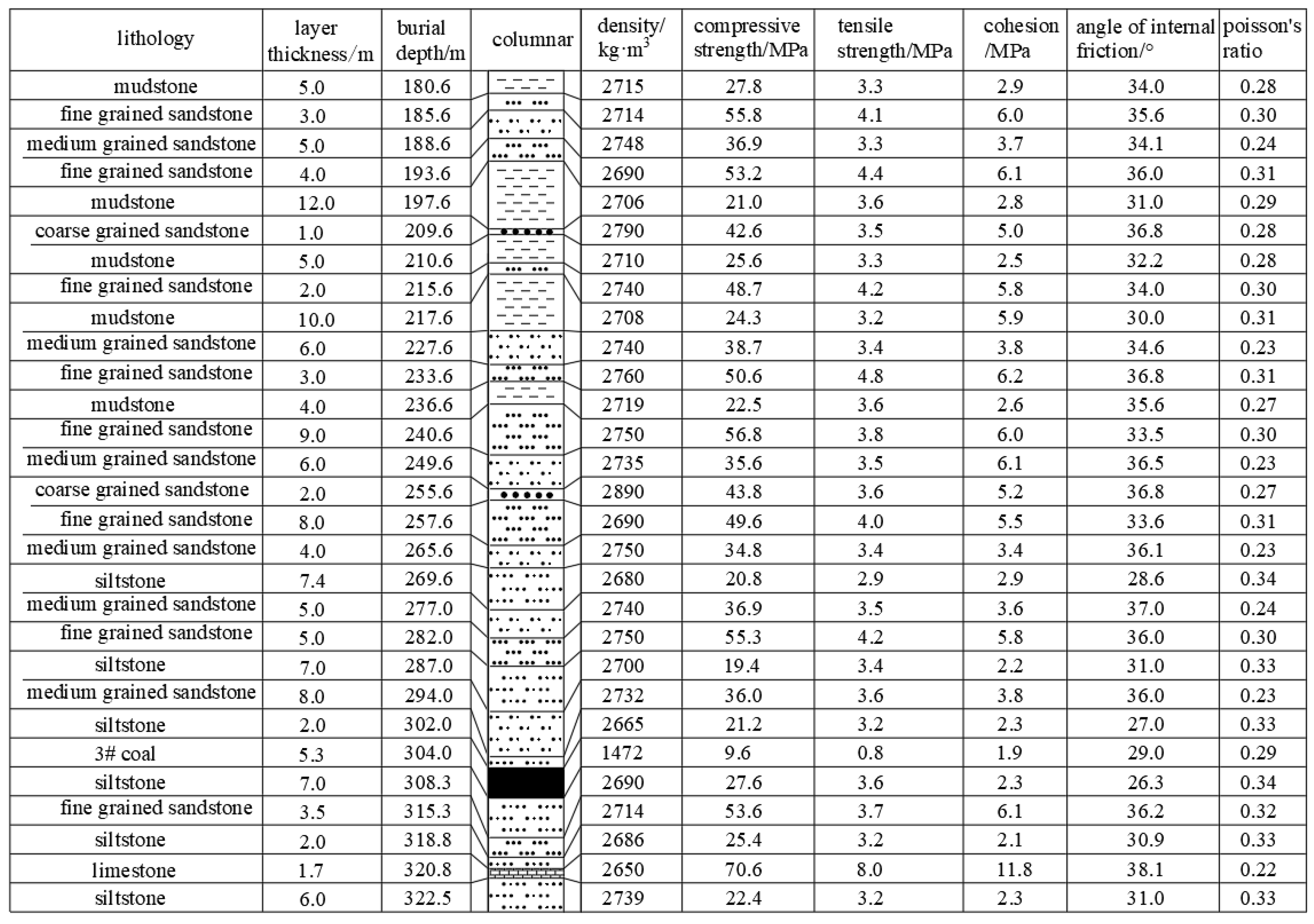
2.2. Geomechanical Characteristics

The top and bottom plates were drilled and peered in the transport groove of the 3206 working face, and the samples were processed. The physical and mechanical parameters measured are shown in Figure 3. Above the working face is the first layer of 2.0 m thick siltstone with a compressive strength of 21.2 MPa. The second layer is 8.0 m thick medium grained sandstone with a compressive strength of 36.0 MPa. The third layer is 7.0 m thick siltstone with a compressive strength of 19.4 MPa. The fourth layer is 5.0 m thick fine-grained sandstone with a compressive strength of 55.3 MPa. The thickness of 3# coal is 5.3 m, and the compressive strength is 9.6 MPa. The direct bottom is 7.0 m thick siltstone with a compressive strength of 27.6 MPa.

3. Mechanism of Entry Instability in Advance Region and Principle of Surrounding Rock Control by Roof Cutting for Pressure Relief

Compared with the working face under normal length conditions, the peak pressure and influence range of the advanced support in front of the coal wall in the ultra-long working face are significantly increased, and the lateral support pressure of the coal pillars on both sides of the isolated working face has significantly increased. Therefore, in the stage of advanced influence of secondary mining, the high lateral support pressure transmitted by the overlying rock on the goaf side is superimposed with the advanced support pressure of the current mining face, and the stress concentration coefficient increases. The peak value develops towards the deep part, and the surrounding rock pressure of the roadway in the advanced area of the goaf retaining roadway working face increases sharply.
By using top cutting and pressure-relief technology to manually intervene in the fracture position of the basic roof, the roof of the goaf collapses along the cutting line, shortening the length of the roof cantilever beam and reducing the pressure on the coal pillar from the overlying rock cantilever beam structure, thereby reducing the lateral solid surrounding rock stress on the goaf and ensuring the stability of the surrounding rock when reusing the roadway [22]. Figure 4a and Figure 4b respectively show the overlying rock structure before and after the top cutting of the 3203 working face. As shown in the figure, under the condition of no top cutting, the boundary structure of the overlying rock on both sides of the isolated working face is F-shaped [23,24]. Due to the asymmetry of the 50 m wide coal pillar and 1.5 m flexible formwork concrete wall left on both sides of the 3203 isolated working face, the length of the cantilever beam on one side of the wide coal pillar is longer, but the area of the wide coal pillar is much larger than that of the flexible formwork concrete wall. Therefore, the load per unit area borne by the flexible formwork concrete wall is greater than that on the side of the wide coal pillar. Under the cutting-top condition, the cantilever beam on the flexible formwork concrete-wall side fractured along the pre-splitting line, greatly reducing the length of the cantilever beam on the flexible formwork concrete-wall side. The boundary structure of the overlying rock on the cutting top-line side changed from a large F-shaped structure to a small F-shaped structure, reducing the load on the flexible formwork concrete wall and the lateral rock stress on the roadway under the same support width condition.
Figure 5a, Figure 5b, and Figure 5c respectively show the principle of floor heave deformation and failure of the roadway supported by uncut flexible-form concrete wall, wide coal pillar-side roadway, and the roadway supported by cut flexible-form concrete wall [25,26]. It can be seen from the figure that under the action of lateral abutment pressure in the gob, the overlying rock pressure acts on the floor of the roadway through the stress-transfer path composed of zones I, II, and III. When the maximum load transmitted to the bottom drum-influence zone exceeds the limit load of the floor rock mass, the plastic deformation of the floor surrounding rock and the floor heave phenomenon will be caused. The failure depth of the plastic zone of the floor of the roadway supported by the flexible-form concrete wall without cutting the top is greater than that of the roadway supported by the wide coal pillar. This is because the static load pressure generated by the cantilevered beams of different lengths at the side of the goaf is transferred to the floor through different supporting systems, such as the wide coal pillar or the flexible-form concrete wall after the mining of the previous working face. The load per unit area of the flexible-form concrete wall is greater than that of the wide coal-pillar side. This difference in stress distribution results in the lower load on the floor heave area of the wide coal-pillar side than that of the flexible concrete-wall side, and the plastic failure depth of the flexible concrete-wall side is greater than that of the wide coal-pillar side, so the floor heave volume of the mining roadway on the flexible concrete-wall side is greater. In order to solve the serious problem of roadway floor heave, the surrounding rock control technology of cutting the top and relieving pressure was proposed. The implementation of the cutting process effectively changed the mechanical transfer mechanism: The length of the equivalent cantilever beam on the side of the flexible-form wall decreases after the top cutting, and this stress redistribution effect significantly improves the stress state of the floor rock mass and reduces the load affected by the floor heave zone and the depth of the plastic failure zone of the floor, which well controls the floor heave deformation and failure.

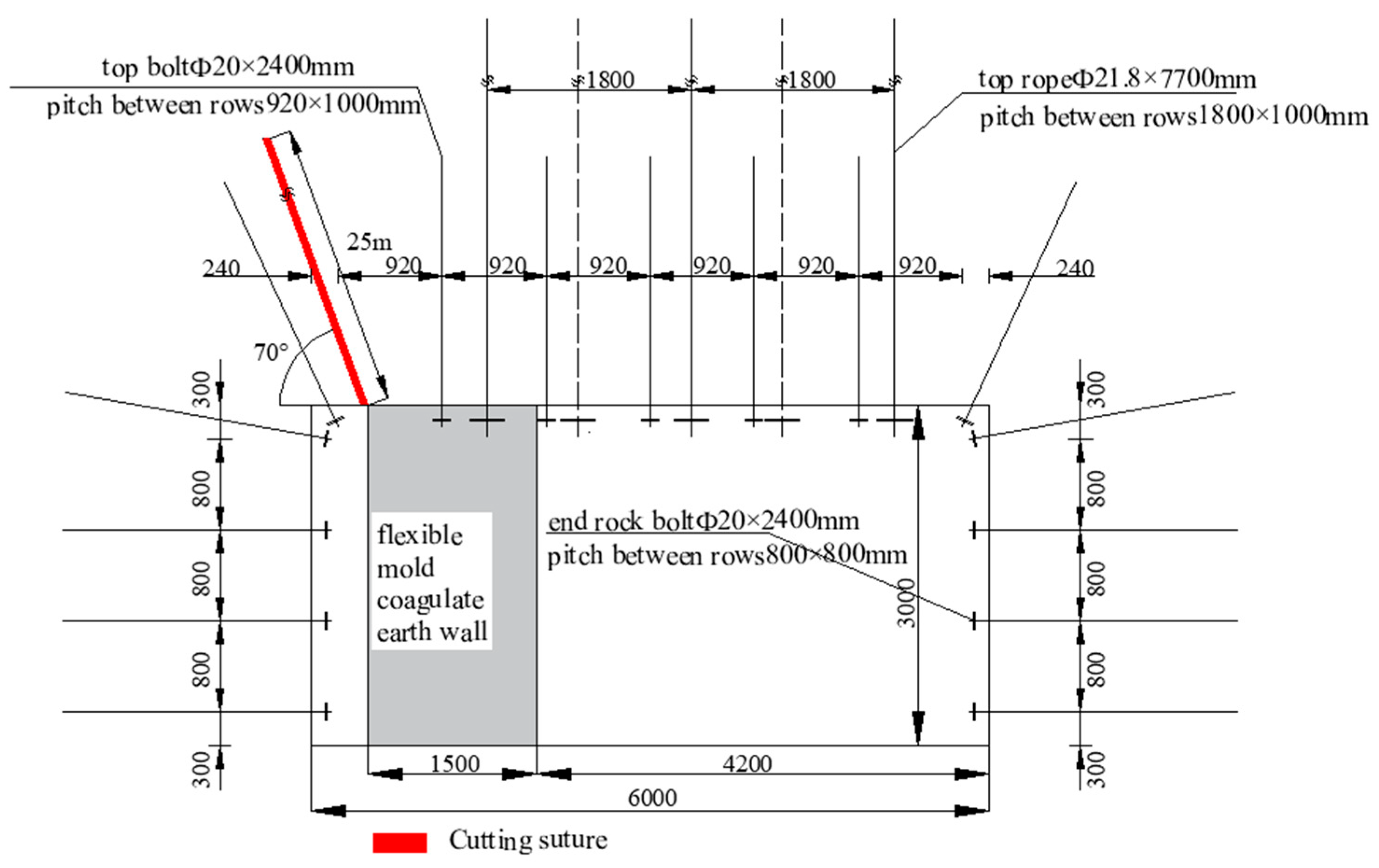
4. Determination of Blasting Top-Cutting Pressure-Relief Parameters

At present, the determination of cutting-top height is mainly based on the swelling theory of rock mass. The cutting-top height should take into account the structure of the overlying hard roof and the fracture migration characteristics of the high rock stratum, so as to ensure that the difficult caving roof can cut smoothly along the weak surface of the cutting top after blasting:
h q = M k p 1
where hq is the cutting height, m; M is the thickness of coal seam, m; and kp is the crushing coefficient of the roof rock. The crushing coefficient is generally 1.2~1.4, but because the direct top is siltstone, kp is 1.25.
According to the engineering geological conditions of 3203 working face, the thickness of coal seam, M = 5.3 m, can be obtained by substituting Formula (1): hq = 17.7 m. When the cutting-top height is 21.2, the cutting-top position is located in 5 m thick fine-grained sandstone, and the cutting-top height needs to be 22 m in order to completely fracture the rock formation. According to the actual site conditions, selecting a top cutting angle of 70° can better ensure the roof caving, so the final cutting parameters are determined as the top-cutting depth of 25 m, and the angle between the slit hole and the plumb line of 20°.

5. Numerical Simulation of Ore Pressure Characteristics of Concrete Wall of Overlong Fully Mechanized Caving Island Face Before and After Cutting Top

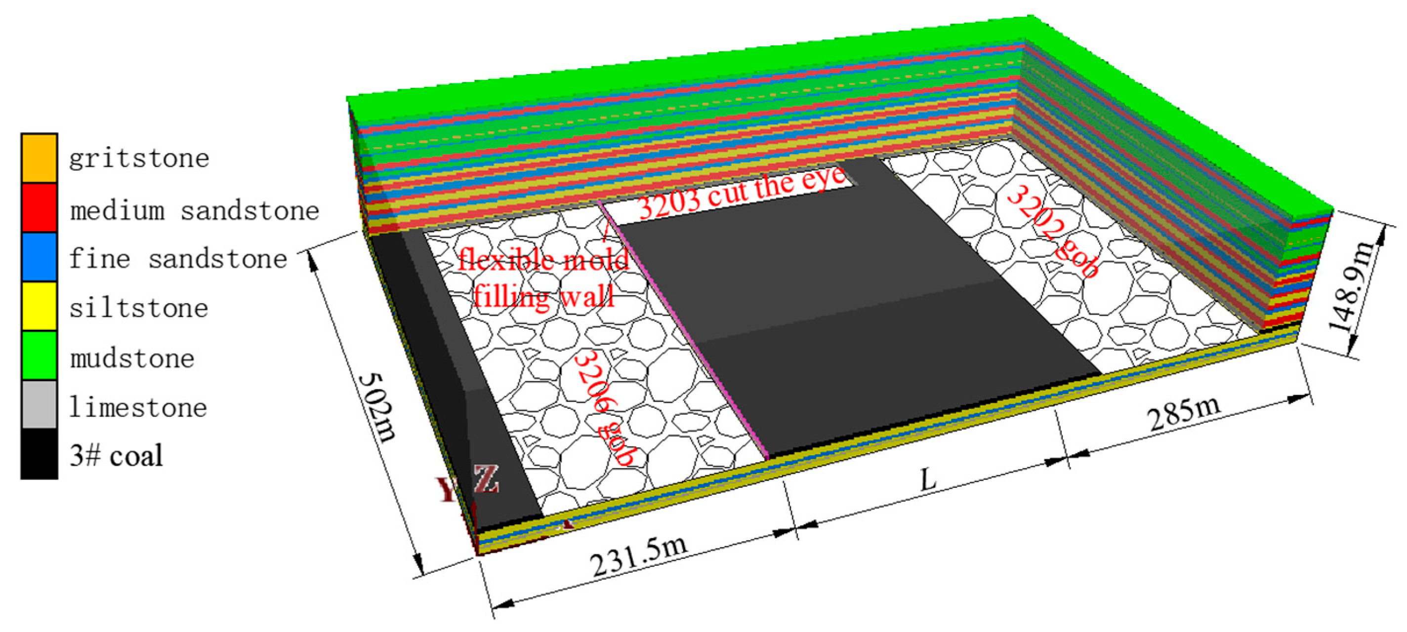
5.1. The Establishment of Numerical Model

Figure 6 shows the numerical calculation model of 3203 ultra-long fully mechanized caving island working face. According to the engineering geological conditions of 3203 fully mechanized caving island working face in Nanyang Coal Industry, FLAC3D6.0 numerical simulation software is used to make a comparative study on the ore pressure characteristics of the flexible-mold concrete wall of the 3203 working face with and without cutting the top after mining. First of all, the model is established, and the model length × width × height = 802 m × 276 m × 148.9 m. The model has displacement boundaries on its four sides and bottom. The lateral sides restrict horizontal displacement, while the bottom constrains both horizontal and vertical displacements. The top of the model serves as a stress boundary where the overburden rock layer’s gravity, γH, is applied as a uniformly distributed load. Here, γ represents the average unit weight of the overburden rock, taken as γ = 26 kN/m³. The rock blocks adopt the Mohr–Coulomb constitutive model, while the goaf filling area employs a double-yield constitutive model. Table 1 and Table 2 respectively present the physical–mechanical parameters of the flexible formwork concrete wall and the stress–strain relationship characteristics of the goaf gangue bearing capacity.

5.2. Numerical Simulation Process

The comparison before and after cutting the top of 3203 ultra-long fully mechanized caving island face is analyzed by numerical simulation. First, 3206 transport trough and track trough were excavated, the roadway was excavated along the bottom of coal seam, and then the 3202 working face was mined, using extremely soft elastic materials to simulate goaf gangue. Then, the 3206 working face was mined, and finally the 3203 transport trough was dug to carry out the mining of the 3203 island working face. When mining the 3206 working face, the 3206 transport channeling was used to retain the roadway along the common flexible-mold concrete wall and the flexible-mold concrete wall along the air for the 3203 track channeling, and the Coulomb–Moore constitutive model was adopted for the flexible-mold concrete wall. The change in lateral supporting stress in the plastic zone of surrounding rock and flexure concrete wall before and after cutting roof is obtained by mining to square position of working face.

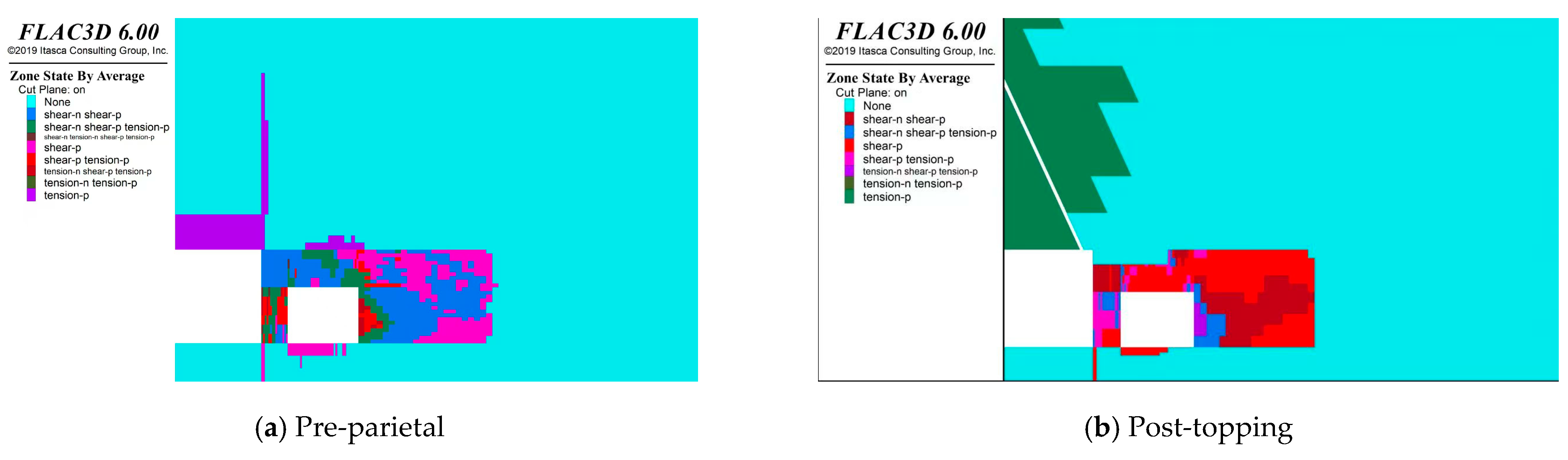
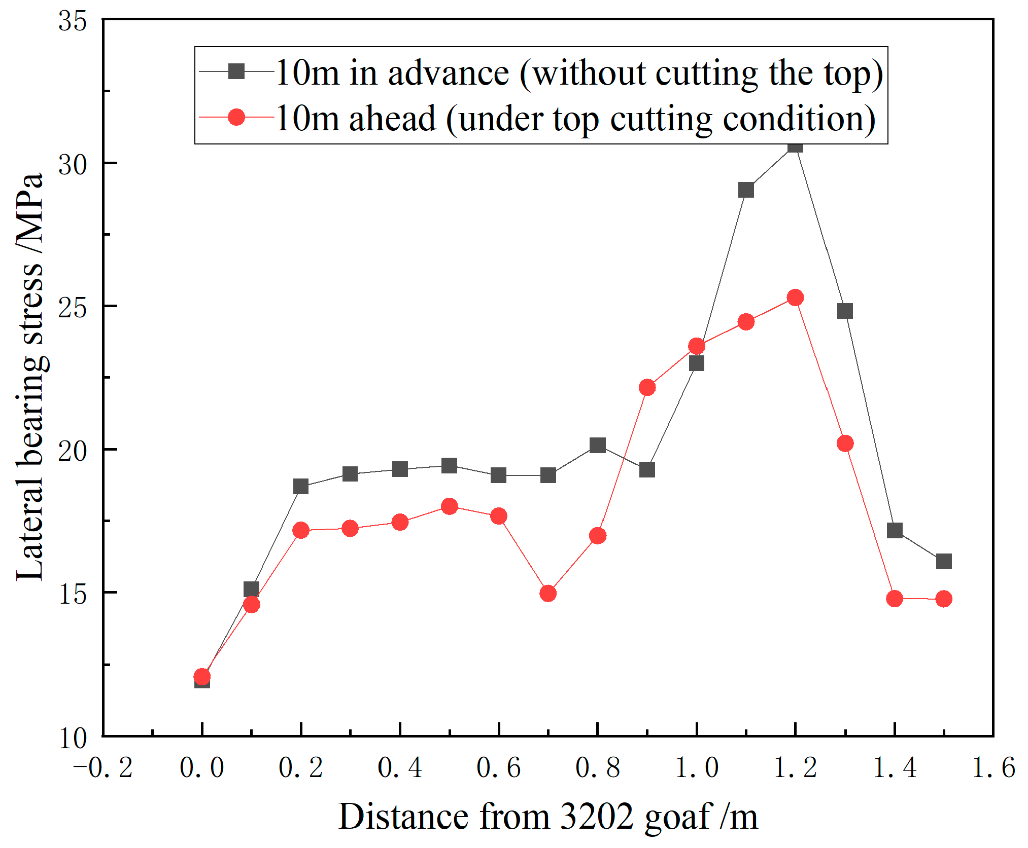
5.3. Numerical Simulation Analysis of Flexographic Concrete-Wall Side Before and After Top Cutting

Figure 7a and Figure 7b respectively show the cloud image of the plastic zone of surrounding rock of the retaining roadway 10 m ahead before and after the top cutting. It can be seen from the figure that the damage of the plastic zone of the roof near the cutting seam of the roadway is significantly reduced after the top cutting, and the plastic zone area of the roadway floor before the top cutting is 2.5 m2. The area of plastic zone after top cutting is 1.3 m2. Compared with the condition of leaving the roadway without cutting the roof, the damage of the plastic zone of the roadway roof near the cutting seam is significantly reduced, and the plastic zone area of the floor is reduced by 1.2 m2 (48.0%). After cutting the top, the depth of the plastic zone of the solid coal wall is reduced by 1.2 m (18.8%), and the control effect of surrounding rock is remarkable.
Figure 8 and Figure 9 respectively show the lateral supporting stress cloud map and the lateral supporting stress distribution curve of the flexographic concrete wall before and after the top cutting at 10 m of the advance working face. As can be seen from the figure, when the top is not cut, the vertical stress of the flexible form concrete wall is 11.9~30.6 MPa, with an average of 20.6 MPa. The peak stress is located 1.2 m away from the goaf 3206, and the peak vertical stress is 30.6 MPa. After cutting the top, the vertical stress of the flexural concrete wall ranges from 12.1 to 25.3 MPa, with an average of 18.2 MPa. The peak stress is located 1.2 m away from the goaf 3202, and the peak vertical stress is 25.3 MPa. The average vertical stress of the flexible form concrete wall is reduced by 2.4 MPa (11.7%) compared with that of the wall without cutting the roof. The peak stress is reduced by 5.3 MPa (17.3%). It can be seen that the cutting of the top has an obvious effect on the side pressure relief of the flexural concrete wall.

6. Field Industrial Test

6.1. Top-Cutting Scheme

In the mining of 3206 working face, the field industrial test is carried out by using the technology of roof cutting and unloading of flexible concrete wall. Figure 10 shows the top cutting and support scheme. According to the geological conditions of the roof of 3206 face, the key parameters of pre-cracking and top cutting are as follows: The seam cutting hole is 300 mm away from the stopping side, and a row is arranged parallel to the top plate of the 3206 transport groove. The spacing is 2000 mm, the diameter of the seam hole is 60 mm, the depth is 25 m, the charging length is 14 m, the mud sealing is 11 m, and the angle between the seam hole and the plumb line is 20° (inclined to the side of the goaf). After the slit hole is completed, a 1.5 m width C30 flexible form concrete wall is built on one side of the goaf of the roadway, and the technology of retaining roadway along the goaf is implemented.

6.2. Mine Pressure Monitoring-Point Layout

The layout scheme of the measuring station is as follows: 185 hydraulic supports are arranged on the working face of 3203, and 6 end hydraulic supports are arranged on the side of the wide coal pillar and the side of the lane, respectively, which are used to compare and analyze the characteristics of the abutment pressure at both ends of the 3203 ultra-long fully mechanized caving island working face after cutting the top. A displacement measuring station is arranged every 25 m on both sides of the mining roadway of 3203 working face, which is used to analyze and compare the deformation characteristics of the surrounding rock of the roadway and the roadway of the wide coal-pillar side after cutting the top, so as to determine the stability of the surrounding rock of the roadway. The positions of the hydraulic support at the monitoring and measuring points No. 6 and 180 and the positions of the monitoring and measuring points No. 21 (62 m away from the cutting eye) and No. 40 (138 m away from the cutting eye) are shown in Figure 1.

6.3. Observation Result

6.3.1. Working Resistance Analysis of End Hydraulic Support

Figure 11 shows the working resistance distribution curve of the hydraulic support at the side of some wide coal pillar and the end of the roadway after cutting the top. As can be seen from the figure, the average resistance of 1# to 6# end hydraulic support is 2635~4455 kN (1# to 6# support is located on the side of the wide coal pillar), and the average resistance of 180# to 185# end hydraulic support is 1403~4356 kN (180# to 185# support is located on the side of the flexible concrete wall). Compared with the wide coal-pillar side, the average working resistance of the hydraulic support at the end of the roadway side after cutting the top is reduced by 992 kN. It is generally believed that the load on the roadway retaining side without cutting the top is greater than that on the wide coal-pillar side [27,28], and the load on the roadway retaining side after cutting the top is lower than that on the wide coal-pillar side through the working resistance analysis of the hydraulic support at the end, so the cutting effect is good.
Figure 12 shows the resistance distribution diagram of the two ends of the hydraulic support after partial topdressing. It can be seen from the figure that the working resistance distribution of the two ends of the hydraulic support is different. The working resistance of the hydraulic support at the end of the roadway is in the form of gradually decreasing with the increase in the resistance in the interval, and most of the working resistance on the side of the wide coal pillar is in the form of uniform distribution. The working resistance of the hydraulic support at the end of the roadway retention side is concentrated in the range of 0~3000 kN, and the working resistance of the hydraulic support at the end of the roadway-retention side is mostly lower than that at the wide coal-pillar side. After roof cutting for pressure relief, the working resistance of hydraulic supports on the gob-side entry is significantly reduced, and the frequency of hydraulic supports exceeding the rated working resistance is greatly decreased, which effectively ensures the safety of the gob-side-entry roadway.

6.3.2. Observation Results of Roadway Deformation

Figure 13 and Figure 14 show the surface position-shift curves of 3203 track channeling and transport channeling at measuring points No. 21 and No. 40, respectively. As can be seen from the figure, the deformation of the surrounding rock of the roadway increases slowly at first and then rapidly as the working face approaches the roadway. By analyzing the monitoring results of all stations, it can be concluded that the total deformation law of the channeling at the side of the lane-retention side is as follows: during the observation period, the displacement of the top and floor is about 85~400 mm, with an average of 264 mm, and the displacement of the floor is about 80%. The proximity between the two sides is about 70~545 mm, with an average of 328 mm. The total deformation law of the longitudinal trough at the side of the wide coal pillar is as follows: during the observation period, the displacement of the top and bottom is about 160~250 mm, with an average of 240 mm, and the displacement of the bottom is about 80%. The proximity between the two sides is about 20~220 mm, with an average of 141 mm. A large number of scholars have analyzed and concluded that the deformation of goaf roadway under the same geological conditions is much greater than that of roadway with wide coal pillar. Through the analysis of the top and floor displacement of the two longitudinal trays, it can be seen that the deformation control effect of track longitudinal trays on the side of flexible-mold concrete wall is close to that of transport longitudinal trays on the side of 50 m wide coal pillar after top cutting and pressure relief, and the deformation control effect of both sides is relatively obvious. By comparing the displacement convergence of the gob-side entry without roof cutting (as shown in Figure 2) with that after roof cutting, it can be seen that the average convergence of the two sidewalls decreased by 24.0% after roof cutting, and the average convergence of the roof and floor decreased by 27.0%. Combined with the previous numerical simulation results, roof cutting effectively reduces the deformation and failure of the surrounding rock on the gob-side-entry roadway.
Figure 15 shows the deformation of the surrounding rock in the advance section of the channeling of track 3203 at the lane retaining side after top cutting and pressure relief. It can be seen from the figure that the deformation control effect of surrounding rock in the channeling of track is good.

7. Conclusions

(1)
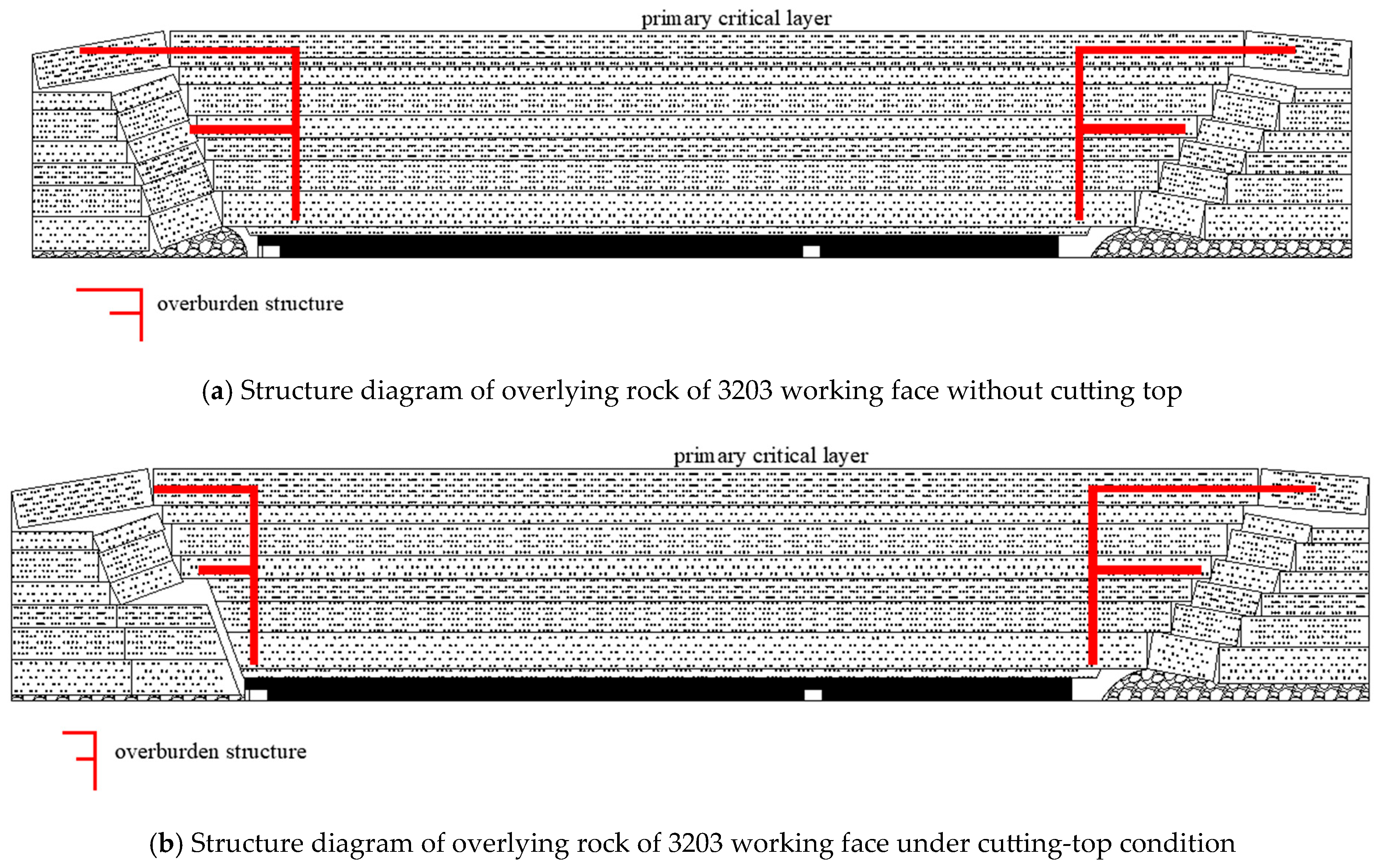
Blast-induced roof cutting effectively reduces the length of the cantilever beam on the flexible formwork wall side, transforming the overlying strata boundary structure from a large-scale F-type configuration to a small-scale F-type configuration. This structural modification decreases the load per unit area acting on the flexible concrete wall, thereby mitigating lateral abutment stress and reducing the load imposed on the floor heave-affected zone. Consequently, these mechanisms synergistically achieve robust control over roadway surrounding rock deformation.
(2)
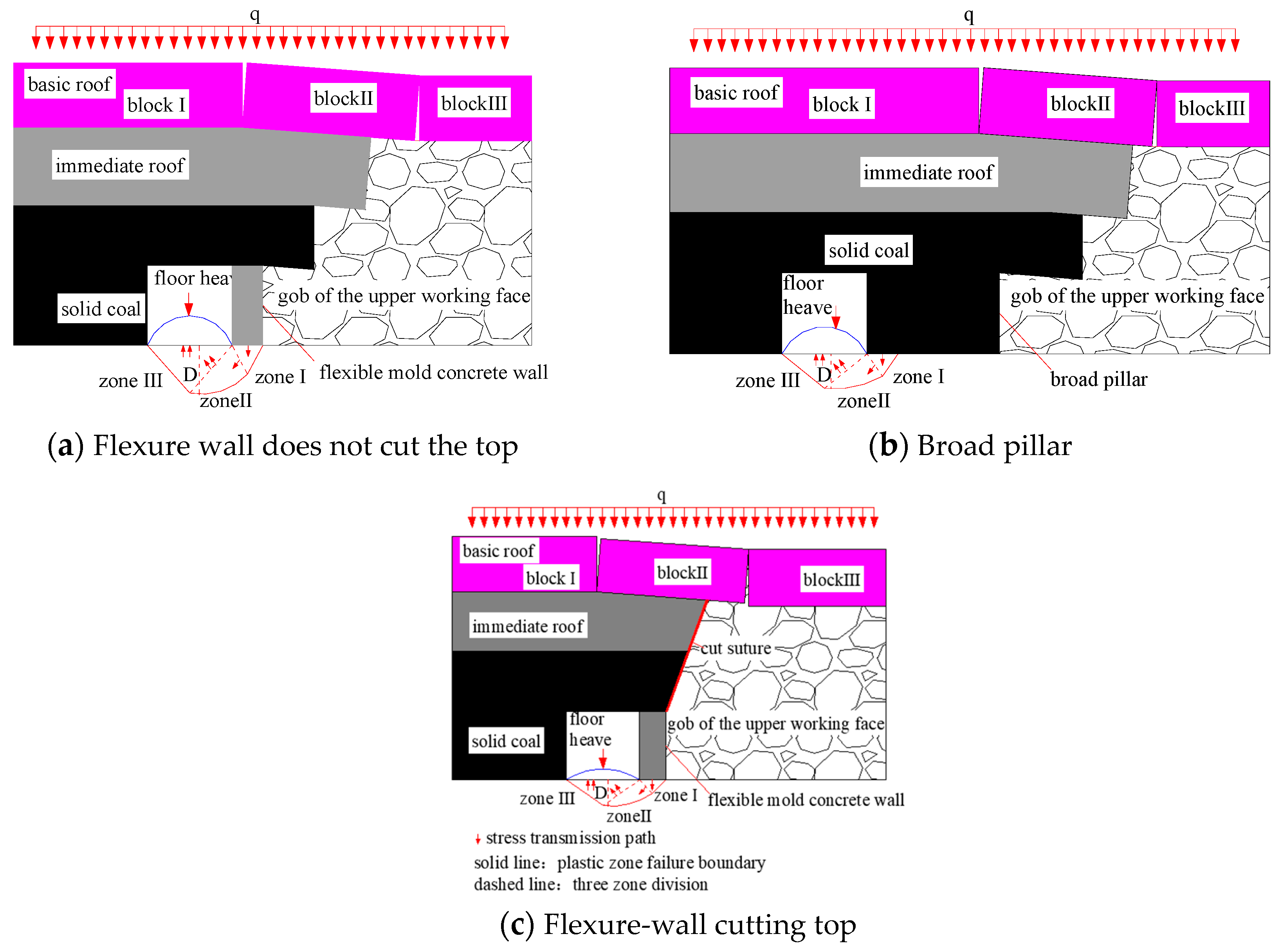
Compared with non-cutting scenarios, roof cutting significantly reduces plastic zone damage in the roof strata adjacent to the cutting line of the flexible concrete wall gob-side entry retaining roadway. Quantitatively, the floor plastic zone area decreases by 48.0%, the solid coal rib plastic zone diminishes by 18.8%, and the average vertical stress is reduced by 11.7%. These metrics conclusively demonstrate the pronounced pressure relief effect of roof cutting on the flexible concrete wall side.
(3)
Compared to the wide coal pillar side, the face-end hydraulic supports on the pillarless gob-side entry retaining side after roof cutting exhibit distinct differences in the distribution patterns and magnitudes of working resistance. As the interval resistance increases, the average working resistance of hydraulic supports on the wide coal pillar side demonstrates uniform distribution, ranging from 2635 to 4455 kN. In contrast, the pillarless side post-cutting shows a declining trend in the frequency distribution of average working resistance, with values ranging from 1403 to 4356 kN, resulting in an average reduction of 30% compared to the non-cutting scenario.
(4)
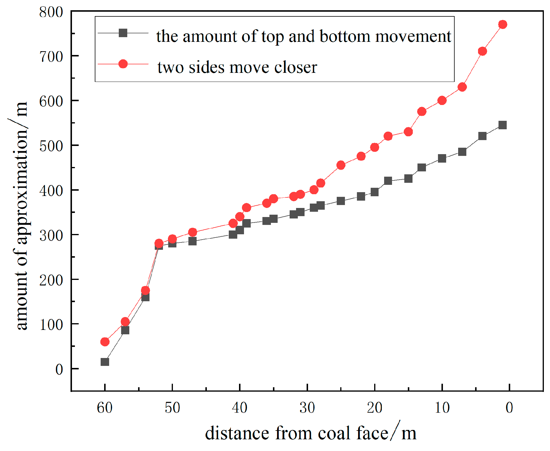
After roof cutting for pressure relief, the surrounding rock deformation control effects of the track entry on the gob-side entry side and the transportation entry on the 50 m wide coal pillar side are comparable. Although the convergence of the two sidewalls in the track entry on the gob-side entry side remains higher than that on the wide coal pillar side, the average convergence of the roof and floor is controlled within 300 mm, the floor heave convergence is within 240 mm, and the average convergence of the two sidewalls is within 350 mm. This effectively ensures safe production.

Author Contributions

Conceptualization, H.W. and J.G.; methodology, H.W.; software, H.W.; validation, H.W., J.G., formal analysis, H.W.; investigation, H.W.; resources, H.W.; data curation, H.W.; writing—original draft preparation, H.W.; writing—review and editing, J.G.; visualization, H.W.; supervision, H.W.; project administration, H.W. All authors have read and agreed to the published version of the manuscript.

Funding

This work was supported by the National Natural Science Foundation of China (Grant Nos. 42472238, 52274091), General Project of Shanxi Province Applied Basic Research Program (20210302123148), and Key R&D Program of Shanxi Province (201903D121075).

Institutional Review Board Statement

Not applicable.

Informed Consent Statement

Not applicable.

Data Availability Statement

The data used to support the findings of this study are included within the article.

Conflicts of Interest

The authors declare no conflicts of interest.

References

  1. He, M.; Gao, Y.; Gai, Q.; Yang, J. Mechanical principle and mining methods of automagical entry formation without coal pillars. Coal Sci. Technol. 2023, 51, 19–30. [Google Scholar]
  2. Lang, D.; Chen, S.; Yuan, H.; Yu, J.; Yu, Y.; Luo, S.; Hu, B.; Xie, P. Study of Reasonable Roof Cutting Parameters of Dense-Drilling Roof Cutting and Pressure Relief Self-Forming Roadway in Non-Pillar Mining. Appl. Sci. 2025, 15, 2685. [Google Scholar] [CrossRef]
  3. Li, Z.; Zhang, Y.; Ma, Q.; Zheng, Y.; Song, G.; Yan, W.; Zhang, Y.; Hu, L. The Floor Heave Mechanism and Control Technology of Gob-Side Entry Retaining of Soft Rock Floor. Sustainability 2023, 15, 6074. [Google Scholar] [CrossRef]
  4. Zhang, Z.Z.; Bai, J.B.; Wang, X.G.; Xu, Y.; Yan, S.; Liu, H.L.; Wu, W.; Zhang, W.G. Review and development of surrounding rock control technology for gob-side entry retaining in China. J. China Coal Soc. 2023, 48, 3979–4000. [Google Scholar]
  5. Qiang, X.; Li, J.; Chen, C.; Dong, J.; Zheng, Y.; Chen, Z. Nonuniform Deformation Instability Mechanism of Gob-Side Entry Retained in Inclined Coal Seam and Stability Control. Appl. Sci. 2023, 13, 8727. [Google Scholar] [CrossRef]
  6. Sakhno, I.; Sakhno, S.; Kamenets, V. Stress environment around head entries with pillarless gobside entry retaining through numerical simulation incorporating the two type of filling wall. IOP Conf. Ser. Earth Environ. Sci. 2022, 1049, 012011. [Google Scholar] [CrossRef]
  7. Sakhno, I.; Sakhno, S.; Skrzypkowski, K.; Isaienkov, O.; Zagórski, K.; Zagórska, A. Floor Heave Control in Gob-Side Entry Retaining by Pillarless Coal Mining with Anti-Shear Pile Technology. Appl. Sci. 2024, 14, 4992. [Google Scholar] [CrossRef]
  8. Sakhno, I.; Isayenkov, O.; Rodzin, S. Local reinforcing of footing supported in the destroyed rock massif. Min. Miner. Depos. 2017, 11, 9–16. [Google Scholar] [CrossRef]
  9. Huang, B.X.; Liu, C.Y.; Zhen, B.S.; Cheng, Q.Y. Distribution abutment pressures on laneway pillars for superwide isolated fully mechanized top coal caving face. Chin. J. Geotech. Eng. 2007, 29, 932–937. [Google Scholar]
  10. Liu, C.Y.; Huang, B.X.; Meng, X.J.; Yang, P.J.; Chen, L.G. Research on abutment pressure distribution law overlength isolated fully-mechanized top coal caving face. Chin. J. Rock Mech. Eng. 2007, 26, 2761–2766. [Google Scholar]
  11. Fan, Z.; Fu, S.; Pan, L. Study on caving structure characteristics of overlying strata in deep super long island working face. Coal Eng. 2020, 52, 86–90. [Google Scholar]
  12. Miao, X.X.; Qian, M.G. Broken feature of key strata and its influence on rock pressure in super-length fully-mechanized coal face. Chin. J. Rock Mech. Eng. 2003, 22, 45–47. [Google Scholar]
  13. Zhao, T. Application Research on the Flexible Formwork of Pumped-concrete Support in Gob-side Entry Retaining in Shallow Coal Seam. Master’s Thesis, Xi’an University Of Science And Technology, Xi’an, China, 2014. [Google Scholar]
  14. Wu, S. Study on deformation mechanism and construction technology of surrounding rock of gob side entry retaining with flexible formwork wall. Coal Sci. Technol. 2022, 50, 127–135. [Google Scholar]
  15. Pang, D.; Zhou, Y.; Niu, X.; He, K.; Li, C.; Chen, Z. Research on the Mechanical Properties of Flexible Material Backfilling Wall in Gob-Side Entry Retaining. Minerals 2022, 12, 1020. [Google Scholar] [CrossRef]
  16. Zhang, Z.; Zhang, H.; Cao, X. Design of small coal pillar reinforcement and double flexible-formwork wall support for retained entry in extra thick coal seam. Coal Eng. 2022, 54, 46–51. [Google Scholar]
  17. Malashkevych, D.; Petlovanyi, M.; Sai, K.; Zubko, S. Research into the coal quality with a new selective mining technology of the waste rock accumulation in the mined-out area. Min. Miner. Depos. Sci. 2022, 16, 103–114. [Google Scholar] [CrossRef]
  18. Kostecki, T.; Spearing, A.J.S. Spearing, Influence of backfill on coal pillar strength and floor bearing capacity in weak floor conditions in the Illinois Basin. Int. J. Rock Mech. Min. Sci. 2015, 76, 55–67. [Google Scholar] [CrossRef]
  19. Habib, K.M.; Vennes, I.; Mitri, H. Laboratory investigation into the use of soundless chemical demolitions agents for the breakage of hard rock. Int. J. Coal Sci. Technol. 2022, 9, 70. [Google Scholar] [CrossRef]
  20. Sakhno, I.; Sakhno, S. Directional fracturing of rock by soundless chemical demolition agents. Heliyon Sci. 2024, 104, e26068. [Google Scholar] [CrossRef]
  21. Zhao, Y.; Song, X. Stability analysis and numerical simulation of hinged arch structure forfractured beam in super-long mining workface under shallow seam. Rock Soil Mech. 2016, 37, 203–209. [Google Scholar]
  22. Li, H.; Zhang, B.; Guo, J.; Yang, Y.; Cui, J. Surrounding rock control technology of roof cutting for pressure relief insmall coal pillar roadway under secondary mining. Min. Saf. Environ. Prot. 2024, 51, 90–97. [Google Scholar]
  23. Zhu, G.A.; Dou, L.M.; Ding, Z.W.; Xie, J.H. Pre-evaluation for rock burst risks in island longwall panel before mining. Chin. J. Geotech. Eng. 2018, 40, 819–827. [Google Scholar]
  24. Dou, L.; He, H. Study of OX-F-T spatial structure evolution of overlying strata in coal mine. Chin. J. Rock Mech. Eng. 2012, 31, 453–460. [Google Scholar]
  25. Huang, P.; Li, M.; Xie, J.; Ren, G.; Zhao, C.; Simao, F.C. Mechanics Model of Floor Heave: Case Study on Thin Coal Seam with Soft Roof and Floor. Appl. Sci. 2023, 13, 9102. [Google Scholar] [CrossRef]
  26. Mo, S.; Sheffield, P.; Corbett, P.; Ramandi, H.L.; Oh, J.; Canbulat, I.; Saydam, S. A numerical investigation into floor buckling mechanisms in underground coal mine roadways. Tunn. Undergr. Space Technol. 2020, 103, 103497. [Google Scholar] [CrossRef]
  27. Yang, P.; Liu, C. Structure Forms of Basic Roof and Reasonable Supporting Parameters in Ends of Fully-Mechanized Top Caving Face. J. Min. Saf. Eng. 2012, 29, 26–32. [Google Scholar]
  28. Pang, Y.H.; Gong, S.X.; Liu, Q.B.; Wang, H.B.; Lou, J.F. Overlying strata fracture and instability process andsupport loading prediction in deep working face. J. Min. Saf. Eng. 2021, 38, 304–316. [Google Scholar]
Figure 1. Location diagram of working face 3203.
Applsci 15 05833 g001
Figure 2. Convergence curve of surface displacements in gob-side entry of 3204 working face.
Applsci 15 05833 g002
Figure 3. Borehole column and physical and mechanical parameters of the working face.
Applsci 15 05833 g003
Figure 4. Structural diagram of overlying rock before and after cutting the top of 3203 working face.
Applsci 15 05833 g004
Figure 5. Diagram of the mechanism of floor heave failure under different support conditions. Note: In the figure, zone I is called the active stress zone, zone II is the transition zone, zone III is the passive stress zone, and D is the maximum failure depth of the bottom plate.
Applsci 15 05833 g005
Figure 6. Numerical calculation model of 3203 ultra-long island working face.
Applsci 15 05833 g006
Figure 7. Cloud map of plastic zone of surrounding rock in the roadway before and after top cutting.
Applsci 15 05833 g007
Figure 8. Cloud diagram of lateral support stress of flexible formwork concrete wall before and after top cutting.
Applsci 15 05833 g008
Figure 9. Lateral support stress distribution curve of flexible formwork concrete wall before and after top cutting.
Applsci 15 05833 g009
Figure 10. Schematic diagram of top cutting and support scheme.
Applsci 15 05833 g010
Figure 11. Distribution curve of working resistance of hydraulic.
Applsci 15 05833 g011
Figure 12. Distribution diagram of resistance between hydraulic supports at both ends of the working face.
Applsci 15 05833 g012
Figure 13. Displacement curve of surrounding rock on the side of the roadway after cutting the roof.
Applsci 15 05833 g013
Figure 14. Displacement curve of surrounding rock on the side of wide coal pillar.
Applsci 15 05833 g014
Figure 15. Deformation of surrounding rock on the side of the roadway after roof cutting.
Applsci 15 05833 g015
Table 1. Physical and mechanical parameters of flexible-mold concrete wall.
Density/kg·10−3Poisson’s ratioTensile Strength/MPaCompressive Strength/MPaCohesion/MPaInternal Friction Angle/°
Flexible formwork wall23600.202.0303.238.9
Table 2. Stress–strain relationship of gangue bearing in goaf.
StrainStress/MPaStrainStress/MPaStrainStress/MPaStrainStress/MPa
0.000.000.090.370.181.160.274.21
0.010.030.100.420.191.310.285.18
0.020.060.110.490.201.480.296.61
0.030.100.120.560.211.680.308.89
0.040.130.130.630.221.920.3113.12
0.050.170.140.710.232.200.3223.69
0.060.220.150.810.242.540.3397.74
0.070.260.160.910.252.96
0.080.310.171.030.263.50
Disclaimer/Publisher’s Note: The statements, opinions and data contained in all publications are solely those of the individual author(s) and contributor(s) and not of MDPI and/or the editor(s). MDPI and/or the editor(s) disclaim responsibility for any injury to people or property resulting from any ideas, methods, instructions or products referred to in the content.

