Article

Noise and Vibration Analysis of Electric Oil Pump with Asymmetric Pitch Control for Gearbox in Hybrid and Battery Electric Vehicle

Department of Control and Instrumentation Engineering, Changwon National University, Changwon 51140, Republic of Korea
Appl. Sci. 2025, 15(10), 5779; https://doi.org/10.3390/app15105779
Submission received: 21 April 2025 / Revised: 16 May 2025 / Accepted: 20 May 2025 / Published: 21 May 2025
(This article belongs to the Special Issue Noise Measurement, Acoustic Signal Processing and Noise Control)

Abstract

:
This study proposes an asymmetric pitch control technique for electric oil pumps with symmetric gear-type pumps in order to reduce noise and vibration. For vane pump noise reduction, mechanical asymmetric pitch arrangements of each vane are widely used. However, the mechanical asymmetric pitch arrangement approach is not applicable in gear-type pumps due to structural limitations. The proposed asymmetric pitch control method provides similar effects to the mechanical asymmetric pitch arrangement by employing instantaneous motor torque controls for an electric oil pump with a gear-type pump. The magnitude of motor torque for each pump tooth is determined with an asymmetric pitch formula, which has been widely used for mechanical vane pumps in previous studies and patents. A formula for the shape of instantaneous motor torque is proposed for the analysis of pressure fluctuations of pumps, which is a combination of trigonometric and exponential functions. The calibration factors for the magnitude and shape can be adjusted according to the characteristics of a given pump. The experimental results for a 400 W electric pump show that the proposed method reduced and dispersed the noise peak by approximately 4 dB(A) in comparison with the normal control, and affected hydraulic performance with a less than 1% decrease in flow rate in not only pump-level but also gearbox-level test environments.

1. Introduction

In order to improve the fuel efficiency of eco-friendly vehicles, components that were previously driven by engine power or hydraulics are being converted to electric equivalents [1]. Among them, mechanical oil pumps that are directly connected to the engine and transmission are being replaced with electric oil pumps driven by permanent magnet synchronous motors and controllers [2,3].
Compared to mechanical oil pumps, which operate in proportion to the engine rotation speed, electric oil pumps operate independently of the engine and require relatively high hydraulic pressure and flow rates even when the vehicle is stopped or driving at low speeds. These stopped or low-speed driving conditions make acoustic noise and vibration reduction design of electrical oil pumps even more important than for mechanical pumps.
The sources and composition of oil pump noise are known, and the design technology to reduce them is typically unique to the pump manufacturer, requiring much design experience and knowledge [4]. The main design factors for noise and vibration reduction are the pump blade and tooth shape, clearance, and port shape; by adjusting these shape variables, the internal flow can be improved, and the noise reduction effect can be obtained. As the technology used to reduce noise by changing these shape variables is closely related to pump performance, there is a limit to reducing noise while maintaining hydraulic performance; in other words, while increasing the clearance between the pump rotor and housing and the clearance between the pump teeth can reduce noise, it can also lower the pump’s volumetric efficiency, which will lower its hydraulic performance.
Design technology has been introduced for vane pumps, which involves distributing the frequency band of generated noise by arranging pump vanes with asymmetric pitches to reduce noise in a specific frequency band and avoid resonant frequency bands [5,6,7]. Vane pumps feature a rotor with vanes that slide into and out of it as the rotor turns. This sliding motion creates chambers into which the liquid flows, and as the rotor turns, the liquid is moved to the outlet, where it is discharged as the pumping chamber is squeezed down [8,9]. Gear pumps create flow by pushing liquid through a mesh of teeth between two rotating gears. A drive shaft moves one gear, and this motion moves the other gear. The rotating gears form a liquid seal inside the casing, creating a vacuum at the inlet as the gear teeth separate [10,11]. Gear pumps are extensively used in the automotive industry due to advantages such as small size, light weight, reliable operation, and low production costs [12,13,14]; however, a significant disadvantage is their relatively high noise emission [15].
As each vane of the vane pump independently creates hydraulic pressure, the pitch angle between vanes can be asymmetrically arranged mechanically [16]. In contrast to the vane pump, the gear pump generates hydraulic pressure by the meshing of two rotating gears, which are dependent on each other with the same clearance [17]. Therefore, the pitch angle between each tooth should be symmetrically arranged mechanically.
Compared to mechanical oil pumps, asymmetric pitch control can be applied to drive electric oil pumps under conditions similar to those when applying asymmetric pitch by actively varying the rotation speed and torque of the motor to the gear-type pump, for which mechanical asymmetric pitch cannot be applied.
This article applies the asymmetric pitch control technique to electric oil pumps, based on internal and external gear pumps for which asymmetric pitches cannot be mechanically applied. It also analyzes the noise characteristics through experiments using an electric oil pump with an external gear pump for a transmission, in order to confirm its effectiveness.

2. Pump Geometry and Asymmetric Pitch

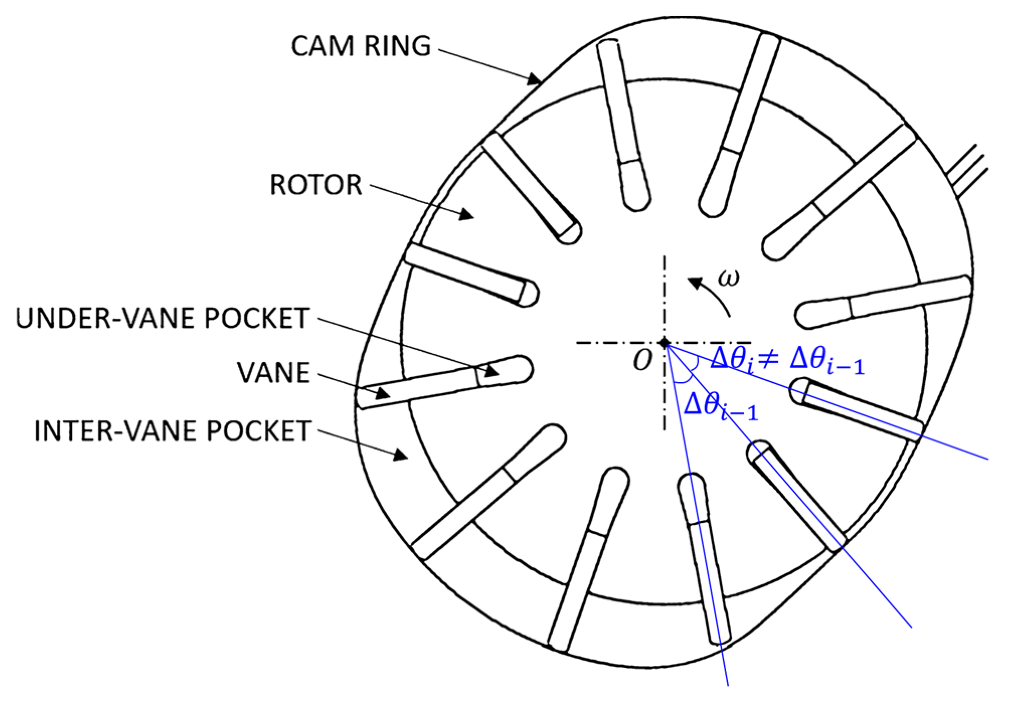
2.1. Asymmetric Pitch of Vane-Type Oil Pump

Figure 1 shows the general form of a vane pump. The vanes are inserted into grooves installed radially in the pump rotor and rotate inwardly in the housing. Applying asymmetric pitches to reduce noise in fluid machines with multiple blades is a generally well-established method [5,7]. For the vane pump shown in Figure 1, the spacing between each blade can be arranged asymmetrically as in Equation (1).
The process of arranging asymmetric pitches mainly uses a random number generator. If the positions of the vanes are arranged randomly, there is a lack of design basis for the determined shape, so the effect must be experimentally confirmed through noise and vibration analyses. In addition, since the random number arrangement cannot be artificially adjusted, much trial and error is required to derive the optimal arrangement [6]. In order to solve the above problems an asymmetric pitch generation function is required, which prevents vane drift in a specific part while arranging the vanes with asymmetric pitches and reduces the sound pressure peak, as well as generating the asymmetric pitch periodically to make it easy to predict and control the vane arrangement, as shown in Equation (2) [5].
θ i θ i 1
θ n = 2 π N + 1 n × A m s i n ( P 1 2 π N n ) × c o s ( P 2 2 π N n )
where θ : incremental angle (pitch) between the teeth; n: order of the teeth; N: total number of teeth; A m : distribution magnitude of asymmetric pitch; and P 1 , P 2 : factors exerting an influence on the cycle.

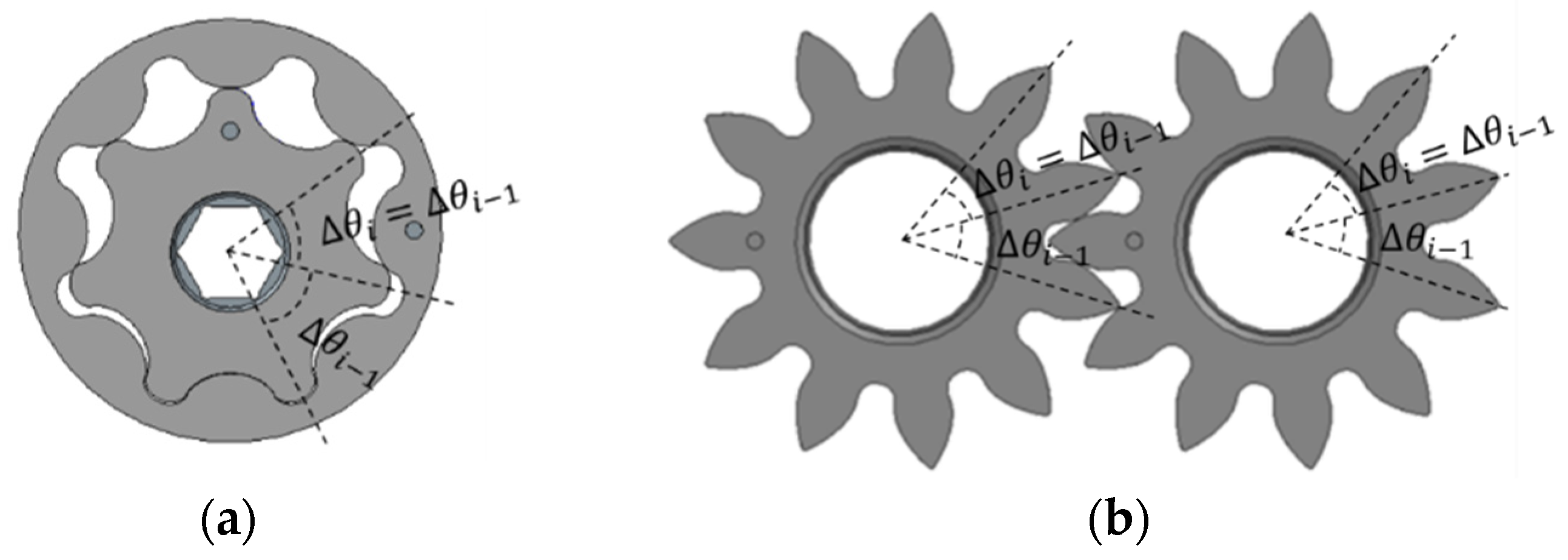
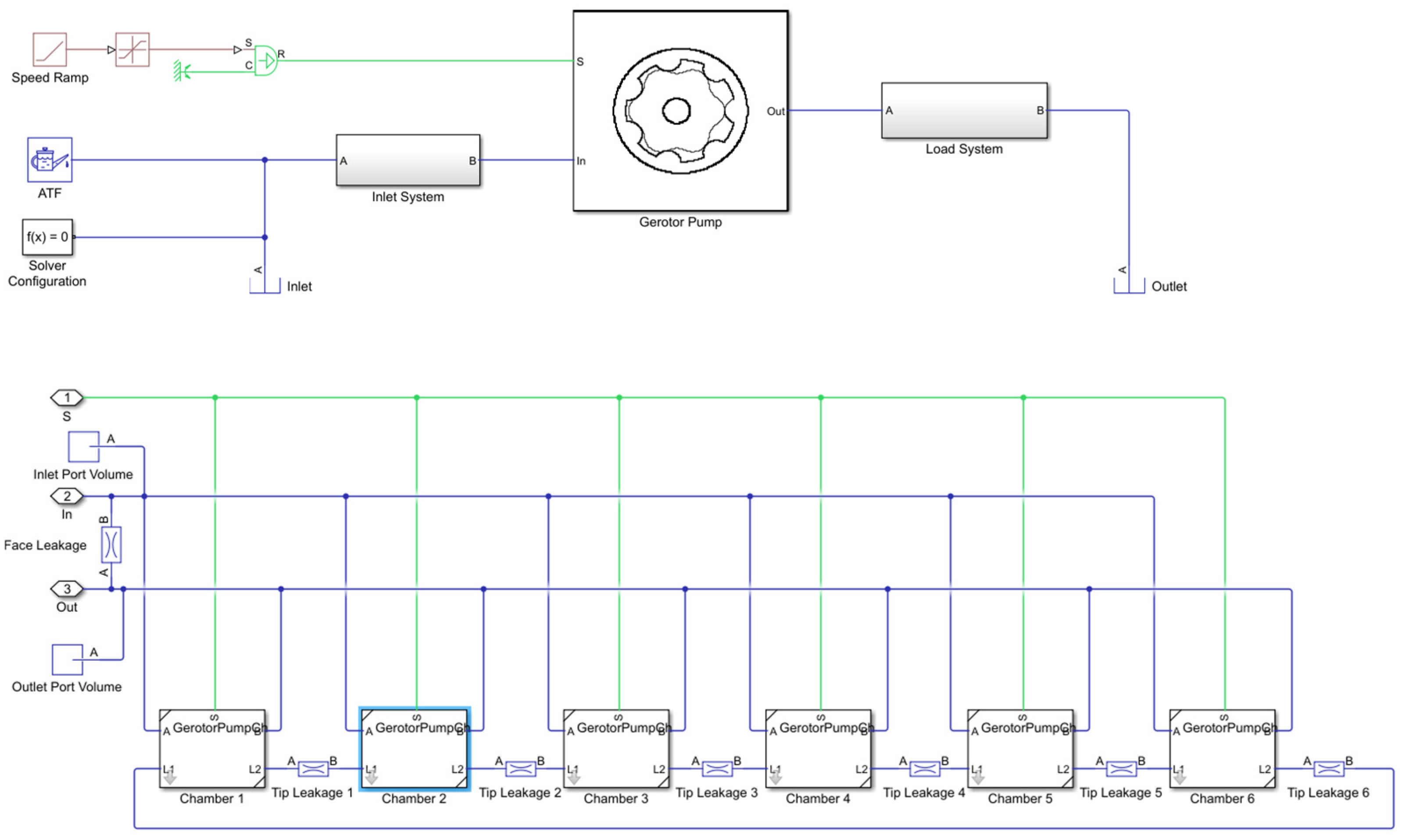
2.2. Shape of Gear-Type Oil Pump

Vane pumps are relatively complex in shape, making them difficult to miniaturize, and are expensive compared to gear-type pumps called internal and external gear pumps. Internal and external gear pumps, which are widely used in automotive oil pumps due to their relatively low cost, generate hydraulic pressure by meshing two gears with the same clearance (as shown in Figure 2), such that the pitch between each tooth must be mechanically symmetric; therefore, asymmetric pitch application is impossible [3].
The main source of noise in internal and external gear oil pumps is hydraulic pulsation, which occurs in various forms depending on the design of the pump’s teeth and port shape, as shown in Equation (3) [18].
V i = b V i m ˙ i = V i d d t p i d d p ρ i + ρ i d d t V i
where A i : the instantaneous area of the i-th chamber of the ump;   V i : the instantaneous volume of the i-th chamber of the pump; ρ i : the instantaneous density of the i-th chamber of the pump;   m i : the instantaneous liquid mass of the i-th chamber of the pump;   p i : the instantaneous pressure of the i-th chamber of the pump; and b: the gear width.
Figure 3 shows the analytical simulation model based on Equation (3), which is formulated based on the geometry of one pump with six teeth. After the pump geometry is designed, the instantaneous hydraulic pulsation can be analyzed by calculating the instantaneous area of each chamber, A i , which varies according to the tip clearance, side (face) clearance, and port shape. Figure 4 shows the analytical simulation results of pressure fluctuation for two different types of pump designs. This study does not explore detailed pump design specifications, which are confidential, but emphasizes that the instantaneous shape of hydraulic pulsations appears differently according to the clearance and inlet/outlet port shape, as shown in Figure 4. These hydraulic pulsations mainly affect the noise and vibration during pump operations.
Gear-type pumps with a mechanically constant tooth-to-tooth gap have relatively uniform hydraulic pulsation depending on the tooth shape during rotation, as shown in Figure 3. Therefore, the spectrum analysis results of the generated noise show that most of the noise is dominated by harmonic components of the base frequency of the product of the rotational speed and the number of teeth.

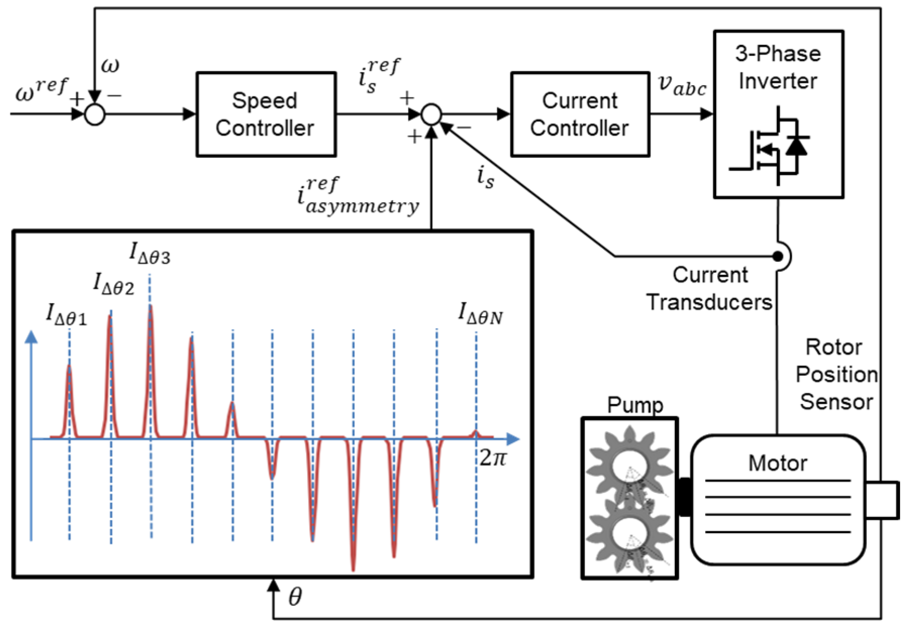
3. Asymmetric Pitch Control

Unlike mechanical oil pumps, which are directly connected to engines and transmissions, electric oil pumps driven by permanent magnet synchronous motors and controllers can actively control the rotation speed and torque of the motor [5].
This section describes the asymmetric pitch control technique that operates internal and external gear pumps, which cannot be applied mechanically to an asymmetric pitch, under conditions similar to applying an asymmetric pitch by modulating the rotation speed and torque of the motor.

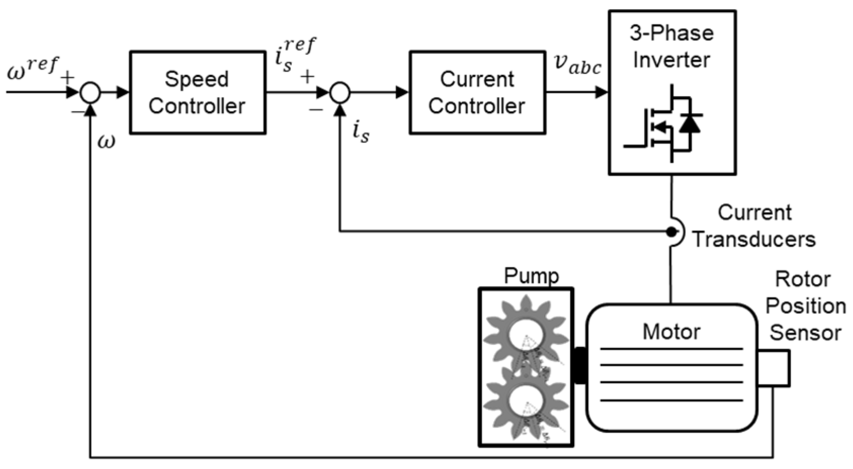
3.1. Control of Permanent Magnet Synchronous Motor

Figure 5 shows the general configuration of the control system of an electric oil pump. The system can be broadly divided into a pump, a motor, a controller, and various sensors such as current transducers and a rotor position sensor [19]. In the figure, ω r e f is the reference of angular velocity, ω is the measured angular velocity, i s r e f is the reference of current, i s is the measured current, and v a b c is the phase voltage.
The voltage reference value obtained through the speed controller and current controller based on the proportional integral (PI) controller is output to the three-phase inverter and controlled. The speed and current values measured by the rotor position sensor and the current sensor are fed back to the control such that the error with the speed reference value becomes 0. As the current of the motor is proportional to the torque, the motor speed and torque can be instantaneously controlled through the two PI controllers [20].

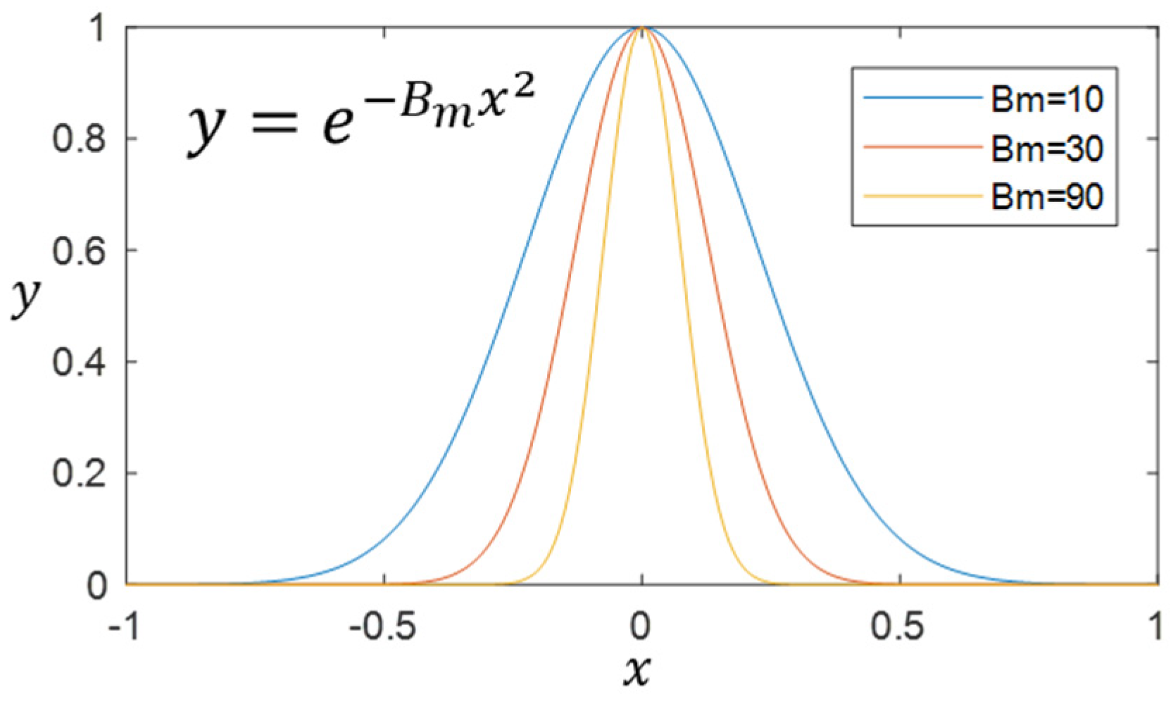
3.2. Design of Asymmetric Pitch Control

After the speed PI controller determines the current reference value, i s r e f , the additional instantaneous current reference value, i a s y m m e t y r e f , for asymmetric pitch control is applied as shown in Figure 6.
The magnitude of the current reference for the asymmetric pitch control is differentially applied to each tooth sequence, as defined in Equation (4) based on Equation (2), which is known as the asymmetric pitch function in previous studies and patents [5]. Through controlling the motor current, the motor torque is instantaneously controlled according to the number of pump teeth and tooth positions. Then, through instantaneously increasing or decreasing the motor torque according to the symmetric position of each tooth, the same effect as applying an asymmetric pitch can be expected.
I θ n = 1 n × A m s i n ( P 1 2 π N n ) × c o s ( P 2 2 π N n )
The shape of the current and torque reference for the asymmetric pitch control should be determined by considering the instantaneous shape of hydraulic pulsation according to the pump design as described in Section 2.2.
The instantaneous shape of an increase or decrease in the motor torque is presented as in Equation (5).
y = e B m x 2
where 1 x 1 , B m represents factors for uneven pitch-simulated control.
This is applied by adjusting the magnitude of B m , which is the asymmetric pitch control shape factor in Equation (5), according to the hydraulic pulsation shape of the pump, interpreted or measured as in Figure 4. Figure 7 shows the shape of asymmetric pitch control according to B m .
Finally, the current reference for asymmetric pitch control for each tooth sequence is implemented as in Equation (6).
i a s y m m e t r y r e f = I θ n × e B m m o d θ , 2 π N 1 2
where mod(a,b) is the modulo operation returns of the remainder of the division of a/b.
To maintain the pump’s hydraulic performance, the average of the control reference should be zero, and its maximum magnitude of current needs to be experimentally determined without deteriorating the performance.

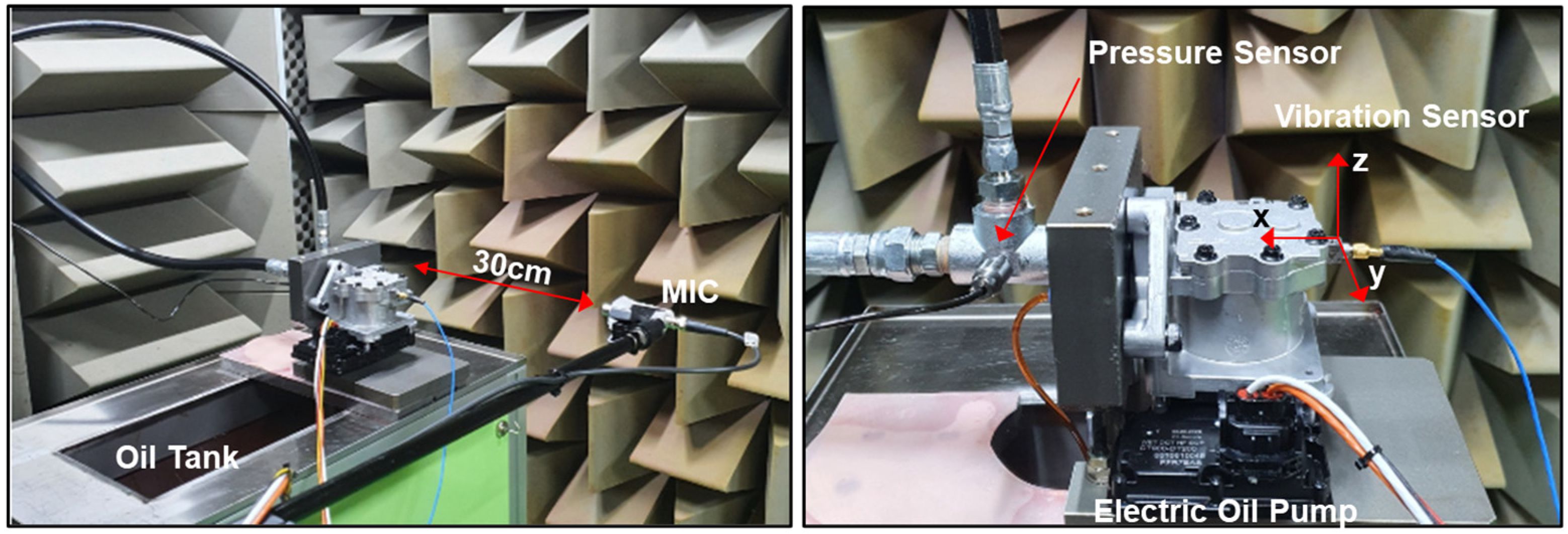
4. Experimental Results

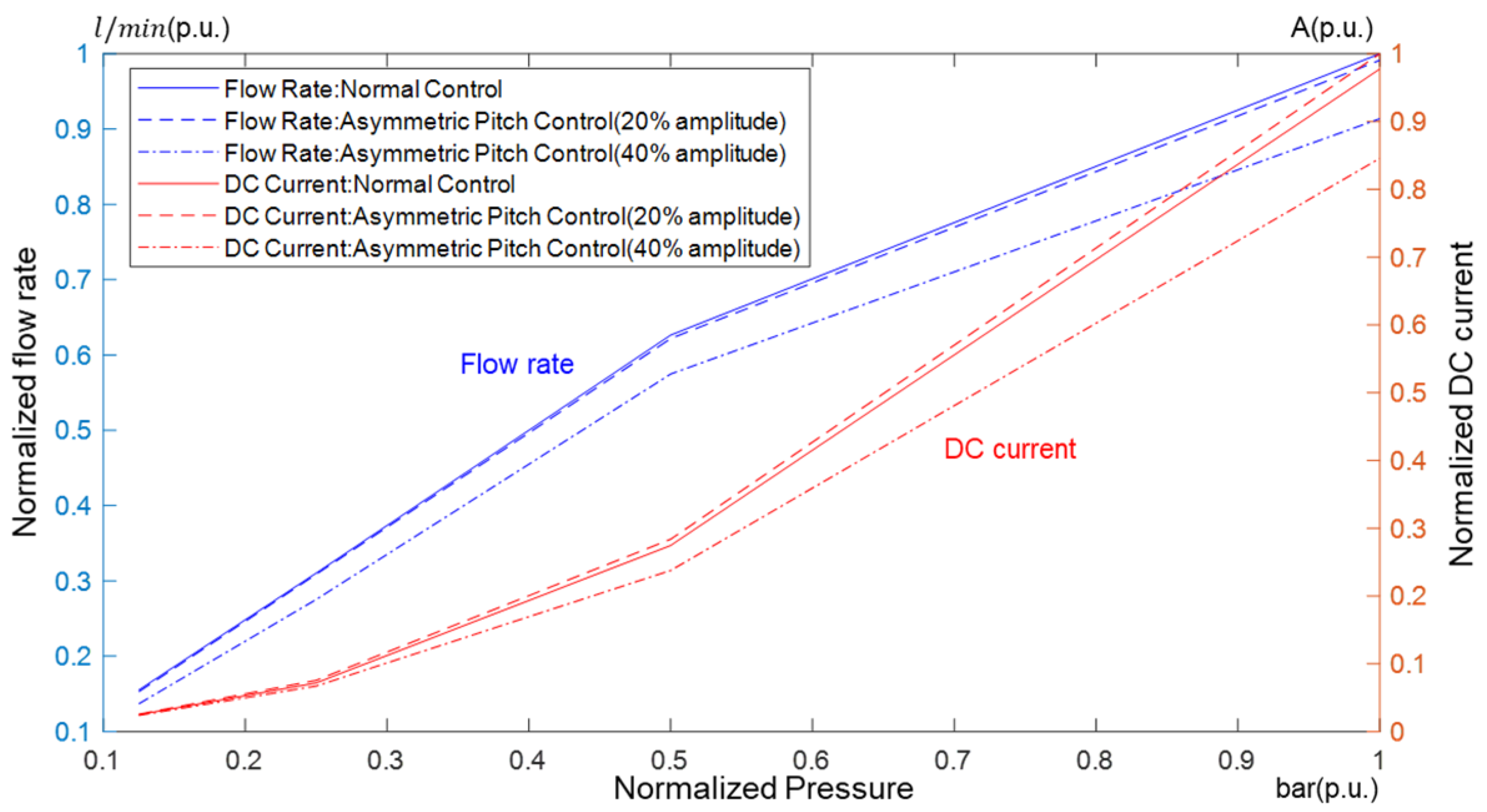
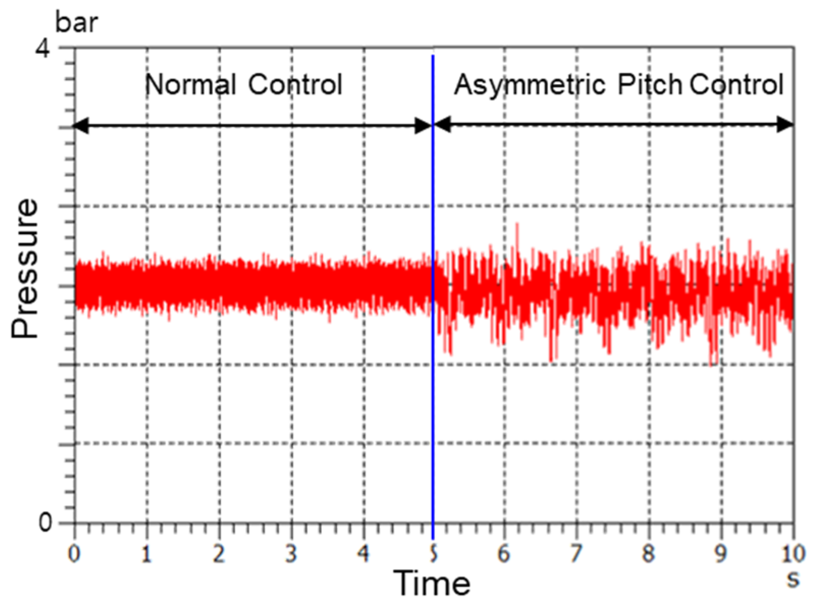
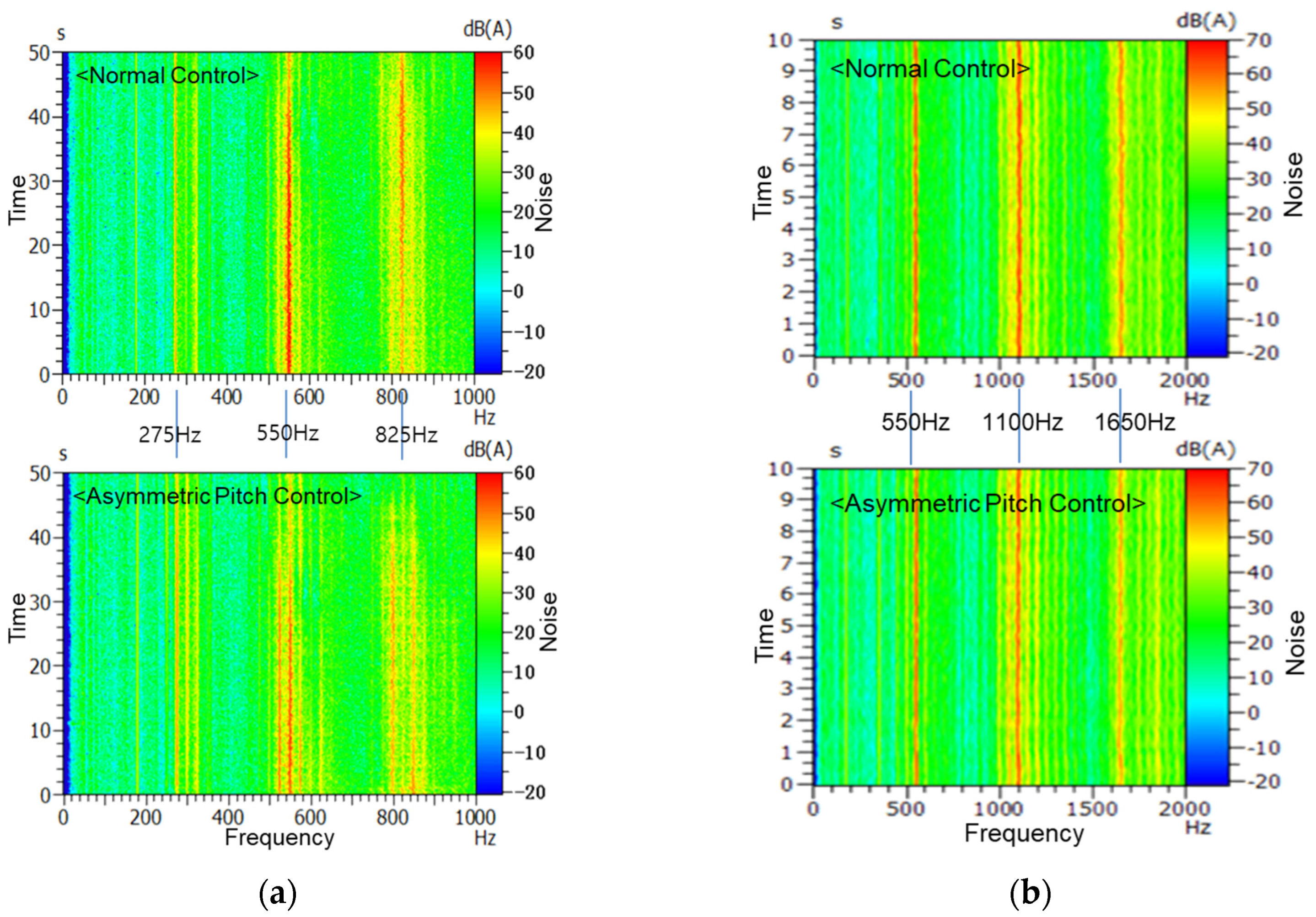
4.1. Pump-Level Test Results

Table 1 provides the main characteristics of the electric oil pump used in the experiment, and Figure 8 shows the experimental environment, including the electric oil pump installed in the anechoic chamber and the location of the installed acoustic noise and vibration sensors. Table 2 provides the control parameters of the electric control unit.
To measure airborne noise that is transmitted directly into the interior of the vehicle through air gaps, a microphone (1/2-inch free-field type, PCB 377B02 amplifier 426E01, 50 mV/Pa) was installed at a distance of 30 cm from the system under tests. To measure structure-borne noise that is transmitted into the interior of the vehicle through the vibration of the pump, a three-axis vibration acceleration sensor (PCB ICP HT356A33, 1.02 mV/(m/s2)) was attached to the surface of the electric oil pump as shown in Photo 1.
Automatic transmission oil (ATF SP-4M) was used, and the oil temperature was 60 °C. A strain gauge-type (MNEBEA NS30T) hydraulic pressure sensor was installed at the pump discharge section to measure the hydraulic pressure. The pump driving speed was tested at 1500 rpm (25 Hz), which is mainly required for low-speed vehicle driving and stopped, and 3000 rpm (50 Hz), which is required for high-speed driving.
Even though the absolute noise and vibration level at 3000 rpm is greater than at 1500 rpm, the impact of pump noise at 3000 rpm is smaller than at 1500 rpm. This is because the pump noise might be drowned out by the vehicle’s driving noise and engine noise when driving at high speeds, which requires 3000 rpm of pump operation. The pump noise at 1500 rpm can be irritating to the driver’s ears when driving at low speeds or when the vehicle is stopped, so noise reduction is required even more during low-speed operations in pumps.
Figure 9 shows the results of comparing the pump hydraulic performance and current consumption according to the application of general control and asymmetric pitch control. It can be seen that when the maximum magnitude of the current reference for the asymmetric pitch control is increased to 40% of the rated current, the flow rate performance is reduced by about 10%. The experiment was conducted by setting the maximum size of the asymmetric pitch control command to less than 20% of the rated current, such that the change in both electric and hydraulic performance was maintained within 1%.
Figure 10 shows the change in pump hydraulic pulsation according to the control method. The asymmetric pitch control shape factor B m was determined to be 30, in order to maintain a similar pulsation width to the hydraulic pulsation measurement results.
The average value of the hydraulic pulsation is the same in both normal control and asymmetric pitch control, but the peak-to-peak value of pulsation in the asymmetric pitch control is larger than the normal control, as shown in Figure 10.
Unlike other noise reduction methods, such as mechanical geometric optimization and material optimization of pumps [10], the proposed control method increases the peak value of the pressure pulsations. These increases might affect the durability of pumps and system stability. Therefore, the maximum magnitude of asymmetric pitch control command should be limited, as indicated in Figure 8. Endurance tests of electric oil pumps should be conducted after applying the asymmetric pitch control.
In addition, as the proposed method is based on instantaneous changes in the current command of the electric oil pump, the control performance directly affects the noise characteristics of the system. The gains and execution period for the current controller should be carefully selected, and the real-time property should be secured without delay.
To analyze the effects of these pulsation shape changes, the spectrum analysis was conducted as follows. Figure 11 presents the results of the frequency spectrum analysis of measured noise and vibration when the pump is operating at 1500 rpm. In the case of normal control, the highest peaks of the frequency band are 550 Hz and 825 Hz, which are harmonic components of 275 Hz. The 275 Hz is the combination frequency of the rotational speed (25 Hz) and the number of teeth (11). When the asymmetric pitch control is applied, it can be confirmed that the noise level of the frequencies of 550 Hz and 825 Hz is reduced. In contrast, it was confirmed that the frequency components of 525 Hz, 575 Hz, 800 Hz, and 825 Hz, which are distributed at intervals of 25 Hz based on 550 Hz and 825 Hz, tend to increase symmetrically. This is because the size of the asymmetric pitch control command corresponding to each tooth was set to one rotation cycle, as in Equation (4), and it can be confirmed that this result has the same tendency as the results of a previous study that mechanically applied the asymmetric pitch as in Equation (2) [5,6].
According to the vibration measurement results in Figure 11b, it can be confirmed that the vibration is symmetrically distributed based on 550 Hz, similarly to the noise measurement results. As summarized in Table 3, when the asymmetric pitch control is applied, the maximum peak value of the noise is reduced by 4.5 dB(A), but the overall size of the entire noise is maintained at the same level. This shows that when applying the asymmetric pitch, rather than absolutely reducing the noise, it plays a role in dispersing the frequency components and changing them into a form of noise that is less irritating to the driver’s ears.
Figure 12 shows the results of the frequency spectrum analysis of noise when driving at 3000 rpm (50 Hz). Compared to the 1500 rpm driving condition, the reduction in peak noise at 1100 Hz order frequencies is only 3 dB(A) when applying the asymmetric pitch control, but the tendency to be symmetrically distributed at 50 Hz rotation frequency intervals is the same. As the magnitude of the asymmetric pitch control command value was set to 20% of the rated current, it can be seen that the effect of applying the asymmetric pitch control decreases as the load current increases. Figure 13 shows the noise color map according to the control methods at 1500 rpm and 3000 rpm.

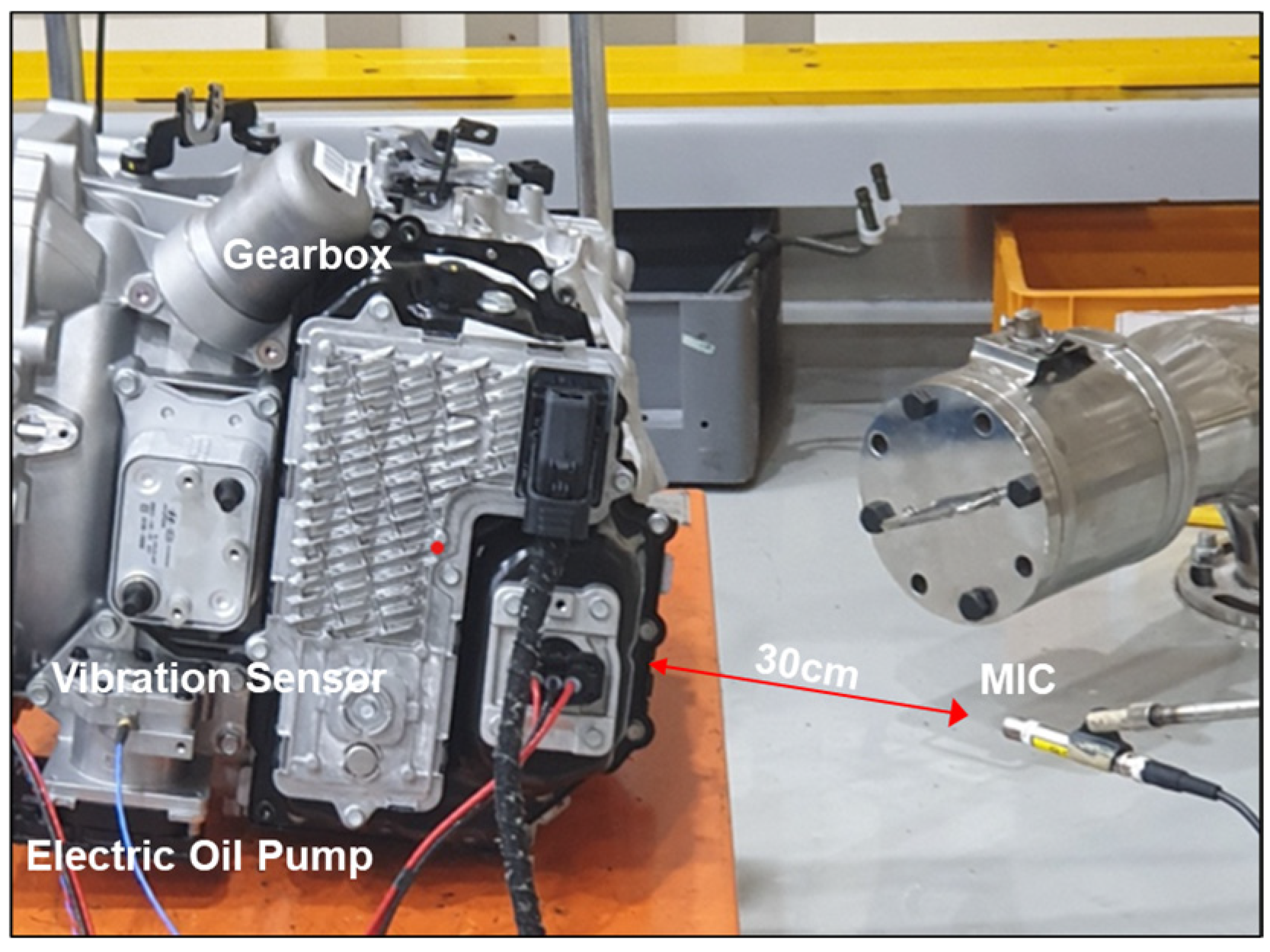
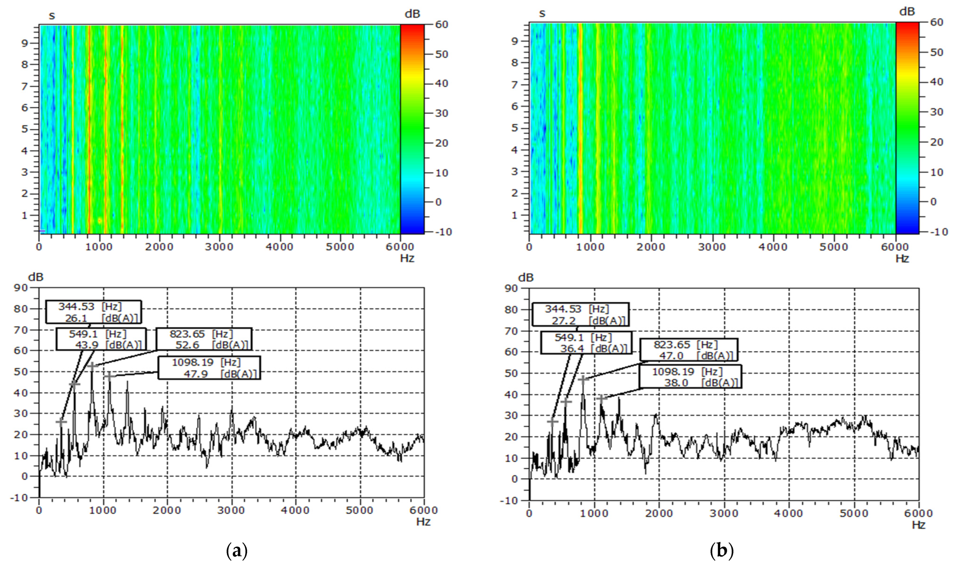
4.2. Gearbox-Level Test Results

Figure 14 shows a measurement setup for a gearbox that is equipped with an electric oil pump. The same microphone and vibration sensor as described in the previous section are used. As shown in Figure 15 and Table 4, the noise level in the frequency band near 825 Hz, which is the harmonic frequency of the pump rotation speed and the number of teeth, is reduced to about 5 dB(A) when applying the asymmetric pitch control. Similar results with the pump-level test were obtained, but the peak noise frequency changed from 550 Hz to 825 Hz due to mounting with the heavy gearbox. The test sample of the gearbox-level test is different from that of the pump-level test in Section 4.1. The samples were randomly selected from mass products, and identical software and control parameters were applied to two different samples. As shown in the experimental results, similar effects were obtained in the two samples. This means the proposed method has robustness in relation to uncertainty in manufacturing.

5. Conclusions

This study proposed an asymmetric pitch control technique that instantaneously varies the motor torque (current) of an electric oil pump based on internal and external gear pumps, which are not applicable for the mechanical asymmetric pitch of each tooth.
The magnitude of the motor current control command for asymmetric pitch was determined using an asymmetric pitch generation function based on a trigonometric function proposed in previous studies and patents for mechanical asymmetric pitch applications. The shape of the motor current control command was proposed in the form of an exponential function, considering the hydraulic pulsation analysis of the pump. Finally, the magnitude and shape factors of the proposed asymmetric pitch control command generation function can be adjusted and applied according to the pump characteristics.
After applying the asymmetric pitch control to the 400 W electric oil pump for the gearbox, the maximum peak reduction of the harmonic frequency and the frequency band dispersion effect were experimentally confirmed through comparison with the normal control.
When applying the asymmetric pitch control, the maximum peak value of the noise was reduced and dispersed by approximately 4 dB(A), while the overall magnitude of the entire noise was maintained at the same level as the normal control. This means the asymmetric pitch control improves noise characteristics such that they are less harsh to the ears of a vehicle driver, rather than absolutely reducing the noise level.
As the proposed method is based on instantaneous changes in the current command of the electric oil pump, it might influence control performance. Instead of applying it to the full-speed driving range, it is expected to be effective in noise reduction by carefully applying it only to a specific driving range; for instance, avoiding resonance points and reducing the peak value of the order frequency that can cause resonance with other parts, such as the engine or transmission.

Funding

This research was supported by Changwon National University in 2023–2024.

Institutional Review Board Statement

Not applicable.

Informed Consent Statement

Not applicable.

Data Availability Statement

The original contributions presented in the study are included in the article, further inquiries can be directed to the corresponding author.

Conflicts of Interest

The author declares no conflict of interest.

References

  1. Lequesne, B. Automotive Electrification: The Nonhybrid Story. IEEE Trans. Transp. Electrif. 2015, 1, 40–53. [Google Scholar] [CrossRef]
  2. Liu, Y.; Zhou, Y.; Wang, J.; Qu, D.; Zhang, F. Hydraulic System Control for a Hybrid Continuously Variable Transmission Based on an Electric Oil Pump. IEEE Trans. Veh. Technol. 2018, 67, 10398–10410. [Google Scholar] [CrossRef]
  3. Beik, O. Design Optimization of a PM Motor: A Practical Approach for Mass Production. IEEE Trans. Energy Convers. 2020, 35, 1849–1858. [Google Scholar] [CrossRef]
  4. Taekwan, S. Analytical Study on Inner Flow and Structural Stiffness in Vane Type of Vacuum Pump. Trans. Korean Soc. Automot. Eng. 2017, 25, 201–206. [Google Scholar] [CrossRef]
  5. Jang, J.-W.; Hwang, Y.-T.; Choi, Y.-S.; Lee, K.-Y.; Jeong, U.-H.; Seiji, M. Random Pitch Impeller for Fuel Pump. U.S. Patent US8092186B2, 10 January 2012. [Google Scholar]
  6. Lee, K.-Y.; Jung, U.-H.; Kim, J.-H.; Kim, C.-H.; Choi, Y.-S.; Ma, J.-H.; Jeong, K.-H.; Park, W.-J. Analysis of Noise Characteristic of Uneven Pitch Regenerative Blower. KSFM J. Fluid Mach. 2015, 18, 71–75. [Google Scholar] [CrossRef]
  7. Zheng, Y.; Jin, X.; Yang, H. Effects of Asymmetric Vane Pitch on Reducing Low-Engine-Order Forced Response of a Turbine Stage. Aerospace 2022, 9, 694. [Google Scholar] [CrossRef]
  8. Stuppioni, U.; Natali, C.; Battarra, M.; Blum, A.; Suman, A.; Pinelli, M.; Dalpiaz, G.; Mucchi, E. Experimental and numerical characterization of the under-vane pressure in balanced vane pumps. Results Eng. 2024, 23, 102439. [Google Scholar] [CrossRef]
  9. Mistry, Z.; Vacca, A.; Uppaluri, S.K. Modeling and experimental validation of twin lip balanced vane pump considering micromotions, contact mechanics, and lubricating interfaces. Simul. Model. Pract. Theory 2024, 133, 102914. [Google Scholar] [CrossRef]
  10. Mitov, A.; Nedelchev, K.; Kralov, I. Experimental Study of Sound Pressure Level in Hydraulic Power Unit with External Gear Pump. Processes 2023, 11, 2399. [Google Scholar] [CrossRef]
  11. Wang, S.; Wang, H.; Li, G.; Li, T. Numerical Simulation Study on Cavitation Characteristics of Circular Arc Spiral Gear Pump at High Speed. Appl. Sci. 2025, 15, 3141. [Google Scholar] [CrossRef]
  12. Shen, H.; Li, Z.; Qi, L.; Qiao, L. A method for gear fatigue life prediction considering the internal flow field of the gear pump. Mech. Syst. Signal Process. 2018, 99, 921–929. [Google Scholar] [CrossRef]
  13. Mitov, A.; Nikolov, N.; Nedelchev, K.; Kralov, I. CFD Modeling and Experimental Validation of the Flow Processes of an External Gear Pump. Processes 2024, 12, 261. [Google Scholar] [CrossRef]
  14. Xu, B.; Liu, Q.; Zhu, Z.; Gao, Y.; Li, C.; Zhang, Y. Influence of the Rotation Speed on the Internal Flow Characteristics of an Aircraft Fuel Gear Pump. Processes 2024, 12, 576. [Google Scholar] [CrossRef]
  15. Huang, P.; Xu, L.; Luo, C.; Zhang, J.; Chi, F.; Zhang, Q.; Zhou, J. A Study on Noise Reduction of Gear Pumps of Wheel Loaders Based on the ICA Model. Int. J. Environ. Res. Public Health 2019, 16, 999. [Google Scholar] [CrossRef] [PubMed]
  16. Natali, C.; Stuppioni, U.; Battarra, M.; Blum, A.; Dalpiaz, G.; Mucchi, E. A novel experimental method for measuring oil film thickness in balanced vane pumps. Measurement 2024, 227, 114254. [Google Scholar] [CrossRef]
  17. Rundo, M.; Corvaglia, A. Lumped Parameters Model of a Crescent Pump. Energies 2016, 9, 876. [Google Scholar] [CrossRef]
  18. Ivanović, L.; Josifović, D.; Ilic, A.; Stojanovic, B. Analytical model of the pressure variation in the gerotor pump chambers. Tech. Technol. Educ. Manag. 2013, 8, 323–331. [Google Scholar]
  19. Choi, C.; Lee, W. Extended Digital Programmable Low-Pass Filter for Direct Noise Filtering of Three-Phase Variables in Low-Cost AC Drives. Energies 2022, 15, 2096. [Google Scholar] [CrossRef]
  20. Choi, C.; Kim, J. Model-Based Angular Position Sensorless Drives of Main Electric Oil Pumps for e-Axles in HEV and BEV. Energies 2024, 17, 4962. [Google Scholar] [CrossRef]
Figure 1. Vane pump with asymmetric pitch [8].
Applsci 15 05779 g001
Figure 2. Structures of gear-type pumps: (a) internal gear type; (b) external gear type.
Applsci 15 05779 g002
Figure 3. Simulink model of the pump with 6 teeth for analyzing pressure pulsations.
Applsci 15 05779 g003
Figure 4. Analytical simulation results of pressure fluctuation according to pump designs.
Applsci 15 05779 g004
Figure 5. Control diagram of electric oil pumps.
Applsci 15 05779 g005
Figure 6. Proposed asymmetric pitch-simulated control.
Applsci 15 05779 g006
Figure 7. Proposed shape of asymmetric pitch control.
Applsci 15 05779 g007
Figure 8. Noise and vibration measurements for the electric oil pump under tests in the anechoic room (The electric oil pump manufacturer: Myunghwa Ind, Co., Ltd., Seoul, Republic of Korea).
Applsci 15 05779 g008
Figure 9. Hydraulic performances according to the control methods.
Applsci 15 05779 g009
Figure 10. Pressure fluctuation according to the control methods.
Applsci 15 05779 g010
Figure 11. Frequency spectrum according to the control methods (1500 rpm): (a) noise; (b) vibration.
Applsci 15 05779 g011
Figure 12. Noise frequency spectrum according to the control methods (3000 rpm).
Applsci 15 05779 g012
Figure 13. Noise color map according to the control methods: (a) 1500 rpm; (b) 3000 rpm.
Applsci 15 05779 g013
Figure 14. Noise and vibration measurements for the gearbox with the pump under test in the anechoic room. (The gearbox manufacturer: Hyundai Transys, Hwasung, Republic of Korea).
Applsci 15 05779 g014
Figure 15. Noise frequency according to the control methods at a 1500 rpm pump operation: (a) normal control; (b) asymmetric pitch control.
Applsci 15 05779 g015
Table 1. Specification of the tested system.
SpecificationsValueUnit
Pump TypeExternal-
Number of Teeth11EA
Max Operating Speed3200RPM
Max Hydraulic Pressure4Bar
Max Hydraulic Flow Rate16lpm
Max Electric Power400W
Table 2. Control parameters of the electric control unit.
Control ParametersValueUnit
MicrocontrollerInfineon TC212-
Execution Period (PWM Period)50μs
Bandwidth of the Current Controller300Hz
Proportional Gain0.002512-
Integral Gain 0.1256-
DC Voltage12V
Table 3. Noise and vibration measurement results at 1500 rpm.
CategoryNoise [dB(A)]Vibration [dB]
OverallMax PeakOverallMax Peak
Normal Control58.252.0134.0118.1
Asymmetric Pitch Control58.047.5133.5113.9
Table 4. Noise measurement results at the gearbox level at 1500 rpm.
CategoryNoise [dB(A)]
OverallMax Peak
Normal Control58.352.6
Asymmetric Pitch Control57.447.0
Disclaimer/Publisher’s Note: The statements, opinions and data contained in all publications are solely those of the individual author(s) and contributor(s) and not of MDPI and/or the editor(s). MDPI and/or the editor(s) disclaim responsibility for any injury to people or property resulting from any ideas, methods, instructions or products referred to in the content.

