1. Introduction
As of 2024, the ancient civil settlement of Ulpia Traiana Sarmizegetusa was on the list of UNESCO World Cultural Heritage monuments, which includes the Roman settlements on the borders (Limes) of the Dacia province.
In this context, the remaining plinth of the central statue in Forum Vetus deserves reconsideration from an archaeological point of view.
From the archaeometrical perspective, there is an opportunity to improve the knowledge on construction materials using modern analytical methods and to assess the reliability and challenges of radiocarbon dating applied to ancient mortars.
Mortars are a wide class of building materials used for more than 8500 years [
1,
2]. Regardless of their formulation, all mortars are made of binder and aggregates. Materials close to our current understanding of mortars are the pozzolanic mortars that originated in Greece around 500 BC [
3]. Romans later improved their use and methods of preparation [
4].
Pozzolanic mortars are made of a pozzolanic material (for example, volcanic ash), slaked lime, water, and aggregates. Pozzolanic reaction takes place between a siliceous or siliceous–aluminous pozzolanic material and slaked lime/calcium hydroxide Ca(OH)
2 in the presence of water, at ambient temperature, leading to the formation of calcium silicate (C-S-H) and calcium aluminate (C-S-A-H) hydrates, which harden over time [
5].
Along with the binder matrix made of hydrated compounds, calcium carbonate CaCO
3 can also be found in mortars [
6]. CaCO
3 in a mortar’s binder phase can originate, in significant amounts, from five sources:
(S1) Non-decomposed CaCO
3 from the original limestone (geogenic calcite) [
7]. This carbonate depends on the processing conditions for obtaining slaked lime and should be minimized, although, in some recipes, it is added intentionally to provide a secondary source of calcite/calcium carbonate, with the idea of regenerating genuine source of carbonates formed by hardening [
4].
(S2) CaCO
3 from carbonation over time of Ca(OH)
2 in excess (pyrogenic calcite); this process may need, for aerial mortars, a carbonation rate of 80–92% after 100 years [
8]. It can occur under ambient carbon dioxide concentrations (with different carbon-14/C-14 contents, depending on the historical period), being thermodynamically favored (exothermal reaction). It is optimal for dating construction segments because it reflects the
14CO
2 level for the construction or restoration time [
9].
(S3) CaCO
3 from carbonation of C-S-H hydrates areas of formation (C-S-H carbonation) [
10]; this specific carbonation can take a variable number of years, depending on microstructural features, weather conditions, microstructure evolution due to micro-cracking, and weathering [
11,
12]. The degree of carbonation of the cementitious materials is, usually, estimated by the measurement of carbonation depth [
12]. Various polymorphs of calcium carbonate, along with S-H/S-A-H and water, are the products of this carbonation process.
(S4) CaCO
3 can be also obtained via recarbonation of Ca(OH)
2 (Ca(OH)
2 recarbonation); over time, a fraction of S1–S3 calcite may eliminate carbon dioxide by dissolution, leading to calcium hydroxide. CaCO
3 regeneration will take place by precipitation using a proximal CO
2 source with a different C-14 signature (older or younger than genuine calcium carbonate formed by hardening) [
13,
14].
Calcium carbonate/calcite, obtained from the S1–S4 sources, will have different levels of carbon-14. Due to its origin and mechanisms of formation, it presents distinct physical and chemical properties and can be separated under certain conditions as fractions. Differentiation between fractions can be achieved using Accelerator Mass Spectrometry, highlighting the formation pathways [
13]. From the geomorphological point of view, calcium carbonate is distributed in nature in three mineral forms: calcite, aragonite, vaterite. Although vaterite can also form in anthropogenic materials such as mortar, it is unstable. Aragonite, on the other hand, can be identified [
15]. However, if it is highlighted by methods of analysis prior to radiocarbon dating, it can be removed [
16].
Mortar maturation means that all these processes have been completed, and an equilibrium reached, long before analyses. The analyses can establish the occurrence of ripening, and also the presence or absence of recarbonation phenomena [
13].
Aggregates constitute a major part of mortars/concretes; ancient pozzolanic mortars were made with natural aggregates, such as sand, limestone, and mussel shells [
17], or artificial aggregates, such as crushed ceramics, which contain aluminosilicates as a pozzolanic material [
18,
19]. When using quarry sand/beach sand or even that from riverbeds, a fifth category of carbonates may appear, which can seriously affect the radiocarbon data these are carbonate deposits/calcareous concretions (S5) (calcareous concretions) [
20].
During formation, porosity plays an important role in carbonation. Pores have a wide range of sizes and shapes in mortars/concretes. Coarse pores greater than 100 μm in diameter are usually formed by the following [
17]: (i)
entrapped air, formed by entrapment of air during mixing. They present both irregular shapes and distributions (and can serve as the primary source of carbon dioxide, at a C-14 level very close to the time of manufacture); (ii)
entrained air pores are round voids formed by organic materials, some of them containing proteins, presenting bubble-like shapes (carbon dioxide will result from the decomposition of organic matter usually close in time to the manufacturing moment). Coarse pores contribute negatively to the strength of the mortar, along with cracks that can occur due to weathering, mechanical actions, and/or chemical reactions, which lead to the formation of higher-molar-volume compounds (developing internal stress that can lead to cracking). By these means, carbon dioxide of a much younger age than the building can appear in a proportion determined by the depth profile toward the building surface.
Interconnected capillary pores contribute to water and air/CO
2 transfer, with their specific formation making a positive contribution to the strengthening of the mortar over time and to its self-regeneration [
4]. In lime-based mortars, pores smaller than 0.1 μm are present in limited amounts and can be identified in hydrated phases. Intermediate-sized pores, of around 50 μm, can be formed between the binder and the aggregate, though decreasing mortar strength. The carbonation reaction of Ca(OH)
2 in mortars is possible if a free pathway exists for water and CO
2 to coexist at the carbonation site. The consequence for ancient lime mortars is that the radiocarbon dating result may be highly dependent on the carbonation depth, the weather conditions, and the air/water/CO
2 mass transfer within a given mortar’s system of pores. The age of carbonation can vary with depth and position (due to the porosity features of a given volume). Also, low amounts of contaminating carbon-bearing compounds (older/younger
14C in organic or inorganic compounds with different radiocarbon ages) can be attributed to complex interactions over time: chemical and biochemical degradation, meteoric waters, human impact, etc. [
21,
22].
With increasing age, the microstructure become denser due to calcium carbonate particles increasing in number and size, thus occupying some of the pores [
23].
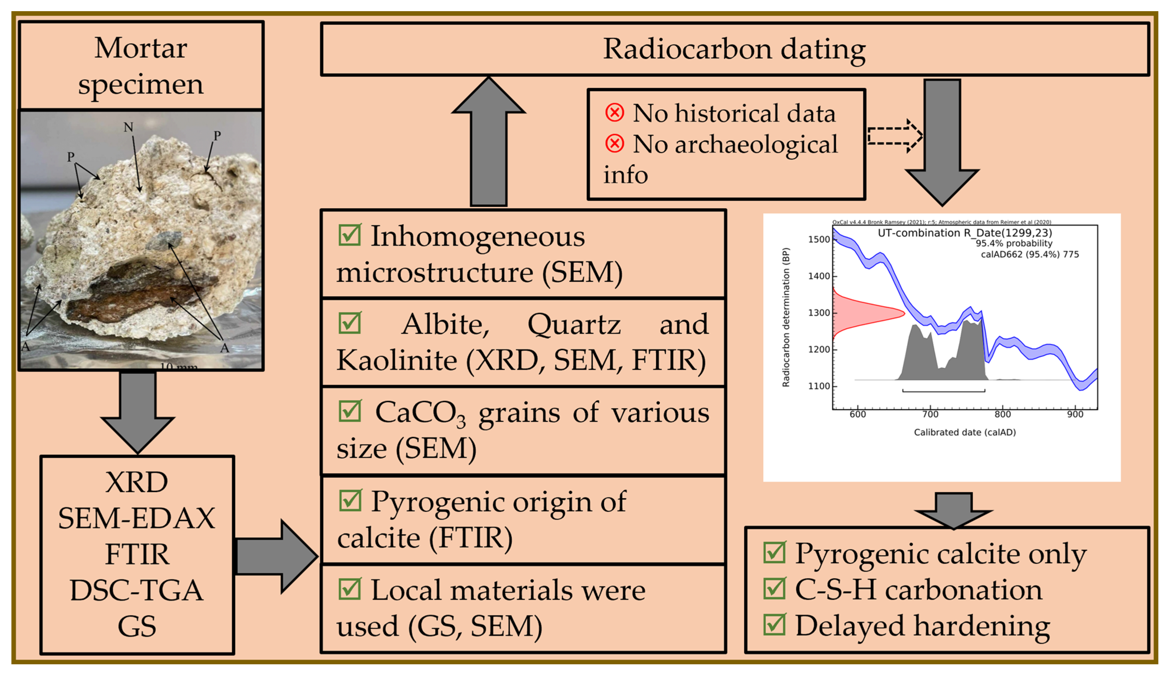
The aim of the present article is to reveal all these interactions and C-14-bearing sources by investigating a mortar collected from the archaeological site Ulpia Traiana, Romania. This was achieved by testing the limitations of analytical methods used in the material characterization of whole mineral fractions and of lump fractions of well-documented archaeological remains.
Through a set of instrumental analyses, the degree of maturation, the presence/absence of S1–S5 calcite sources described above, and occurrence of calcium hydroxide were investigated in relation to the radiocarbon results.
Last but not least, this article shows to what extent, even if sampling is carried out according to the requirements, in the case of concrete-like mortars, a situation arises of radiocarbon ages that differ from the estimates. This is the phenomenon of ‘delayed-hardening mortar’, where the material hardens very slowly, providing much younger radiocarbon ages.
3. Results
3.1. XRD Analysis
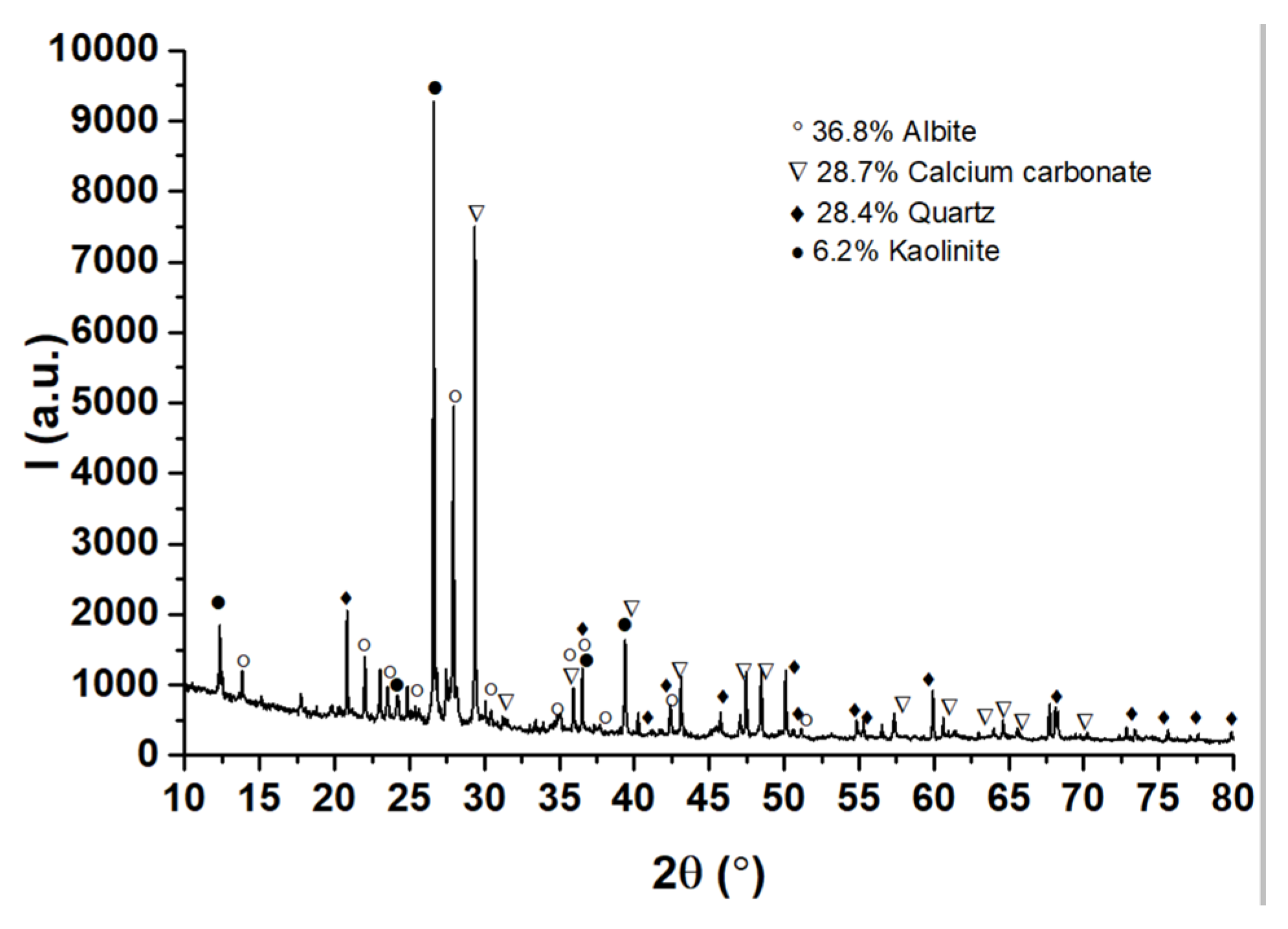
The XRD analysis results in
Figure 4 show that the mortar is rich in the feldspar mineral albite (NaAlSi
3O
8—ICDD PDF4+#00-009-0466), indicating an igneous origin (granite, locally available) of the siliceous component in the original mortar mixture. Quartz (SiO
2—ICDD PDF4+#01-070-3755) and calcite (CaCO
3—ICDD PDF4+#04-023-8700) follow albite in similar percentages, while a small amount of kaolinite (Al
2O
3·2SiO
2·2H
2O
—ICDD PDF4+#00-058-2028) was found. Kaolinite may be used as an ingredient deliberately or accidentally released in the original mortar admixture and/or may be a contaminant accumulated over time.
Starting from the mass percentages provided by XRD, namely, albite (NaAlSi3O8) 36.8%; calcium carbonate (CaCO3) 28.7%; quartz (SiO2) 28.4%; and kaolinite (Al2Si2O5(OH)4) 6.2%, the value of 158.152 mg/’virtual mmole’ of the homogenized mortar can be reached. This can be used to estimate the mass percentage per element: Na—5.37%, Al—8.48%, Si—26.78%, O—49.68%, Ca—7.27%, C—2.27%, H—0.15%.
The value of the mass percentage of carbon contained in the ‘lumps and bumps’ (henceforth called lumps), measured by elemental analysis, was 5.36%C. The nitrogen percentage of 0.1%N determined simultaneously with carbon enters the background threshold during thermal combustion in the EA (see
Section 2.2.) and demonstrates that there is no contamination with organic material containing nitrogen inside lumps.
The value obtained for %C in lumps is 2–2.5 times higher than that for the homogenized mass of mortar, a value determined by XRD, namely 2.27%C (within the limits of experimental errors of the methods, and the material’s inhomogeneity). But it is also 2–2.5 times lower than that for pure calcite (12%C).
A possible explanation is that lumps contain calcite/calcium carbonate together with other chemical elements, unidentifiable to the EA (such as Na, Al, Si, O, Ca, H), or, most likely, the material subjected to graphitization is a mixture of calcite from the time of hardening in construction, rehydrated calcite, secondary calcite, and/or geogenic calcite, together with some impurities from mortar, mentioned before.
The other analyses will bring new information to help define the chemical composition of the lumps as correctly as possible. This information is vital in the selection of the dating strategy and the interpretation of radiocarbon results.
3.2. Microstructural Analysis
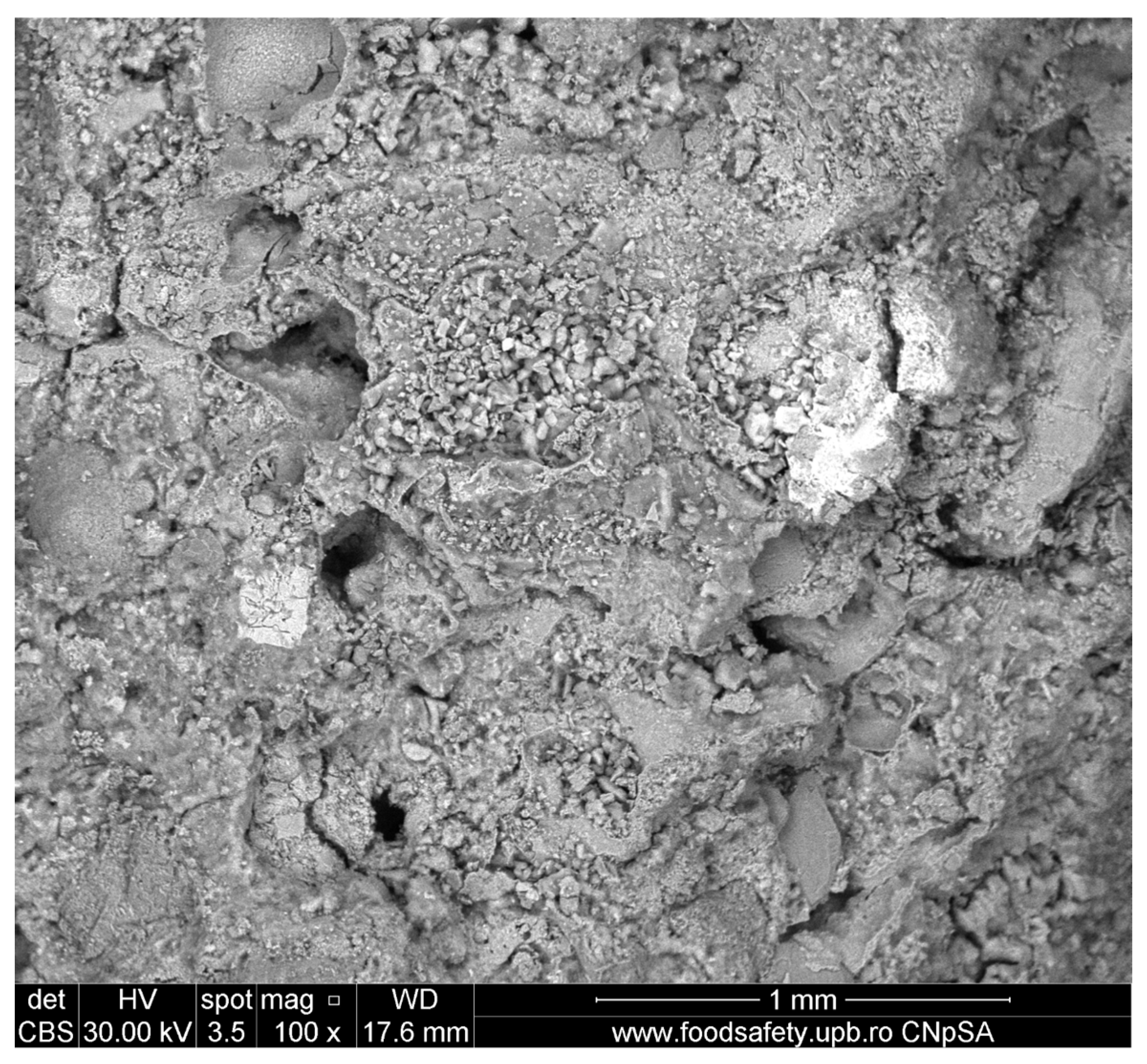
The microstructure was characterized by SEM analysis.
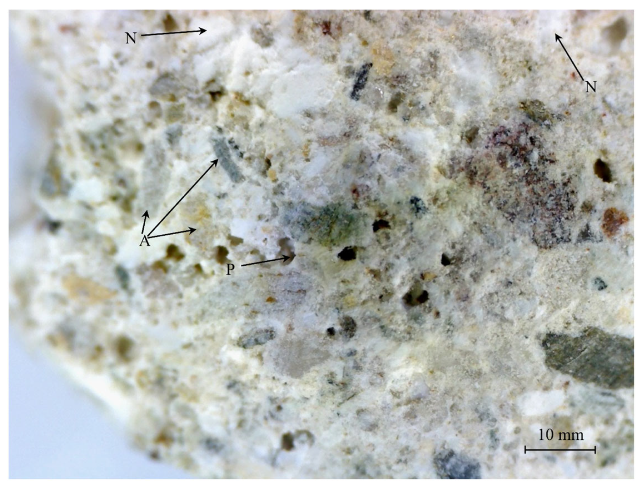
Figure 5 shows a highly inhomogeneous microstructure, with both large and small—and, probably, interconnected—pores and cracks, grains of various sizes, and entrapped air bubbles.
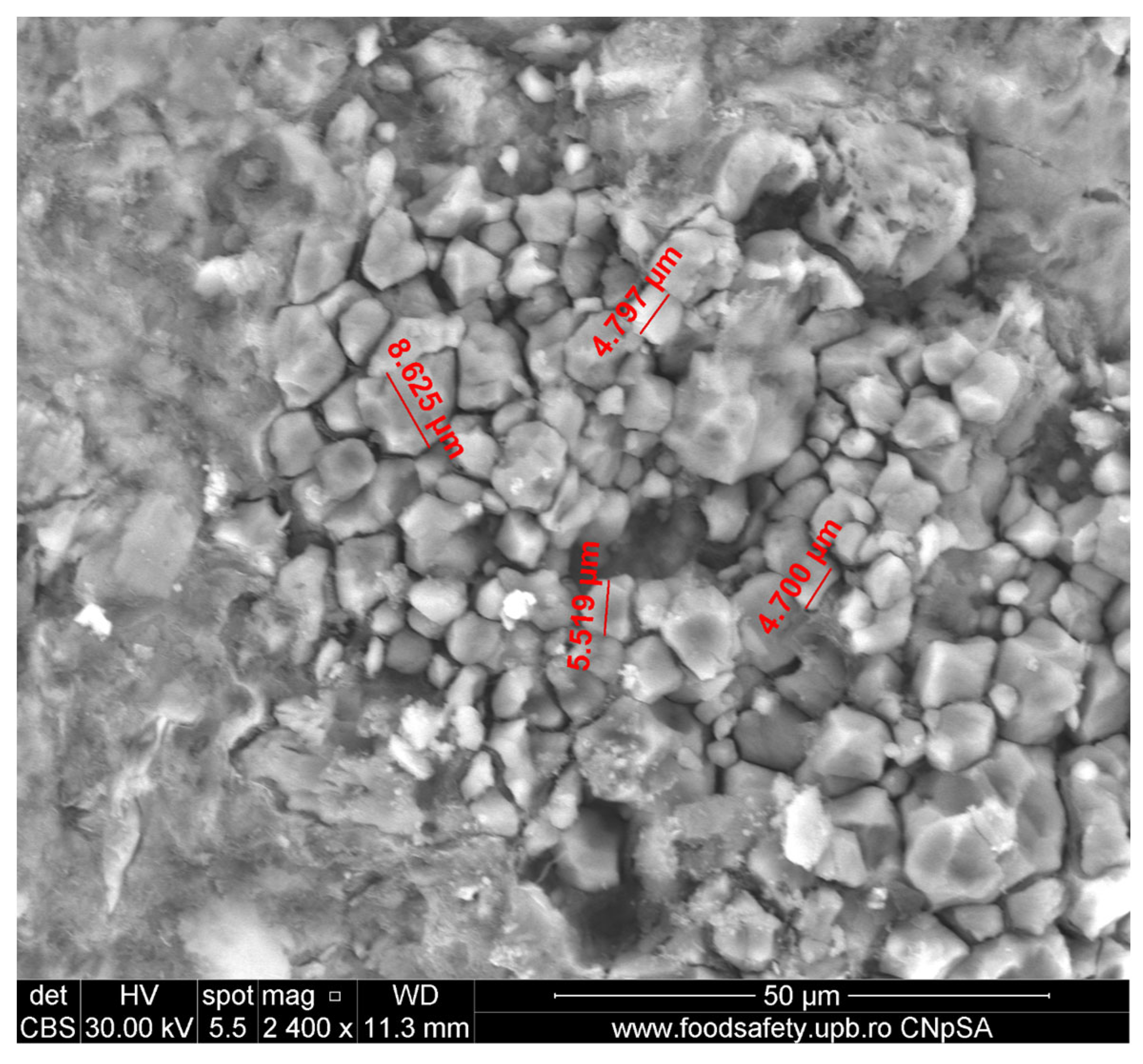
Figure 6 shows a large collection (a nest) of calcite grains with sizes less than 10 microns, which most probably resulted from the carbonation of a relatively big Ca(OH)
2/(CH) site. Although small, calcite grains are, most of them, well developed with well-defined grain boundaries. The nest is surrounded by a dense and compact surface layer that could be a biofilm. These observations reinforce the conclusions from
Section 2.1., excluding the presence of calcareous concretions in the mortar and even more so in the lumps (S5 calcareous concretions), as defined in the
Section 1.
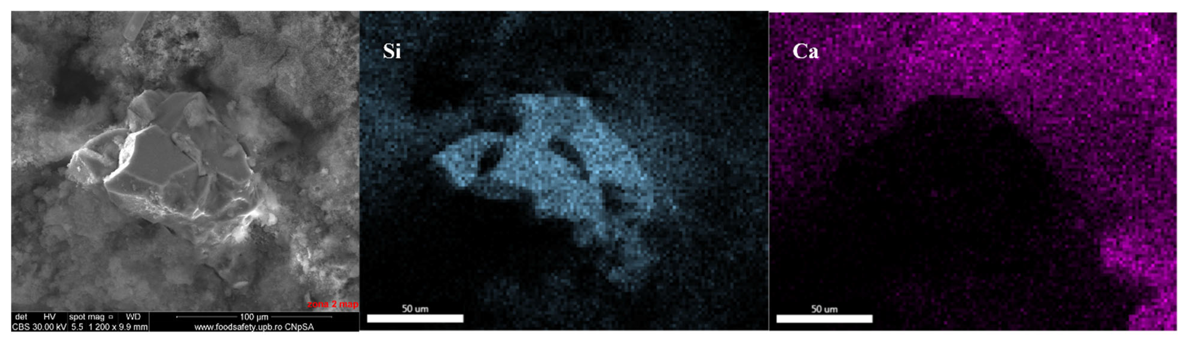
A very small (less than 150 μm in size) silica grain was identified in the fracture, partially connected to the binder matrix, which contains mostly Ca and Si (as Al accounts for only 2.8%), distributed homogeneously—see
Figure 7.
Figure 8 presents an albite grain with partially filled channels on its surface; channels seem to be oriented, almost completely, in diagonal directions. EDAX maps confirm the existence of Na, Al, and Si oxides and spectral analysis confirms the existence of feldspar, identified in XRD (
Figure 4).
The existence of a calcium and phosphorus compound (Ca-P compound) is evidenced in
Figure 9 along with variously sized pores, CaCO
3 lumps, quartz grains, and large areas of binder matrix. The Ca-P compound presents interconnected pores and is well embedded in the binder matrix. Its surface is covered with very small, probably calcium carbonate nodules and may represent a microfragment of bone, as suggested by literature data [
32].
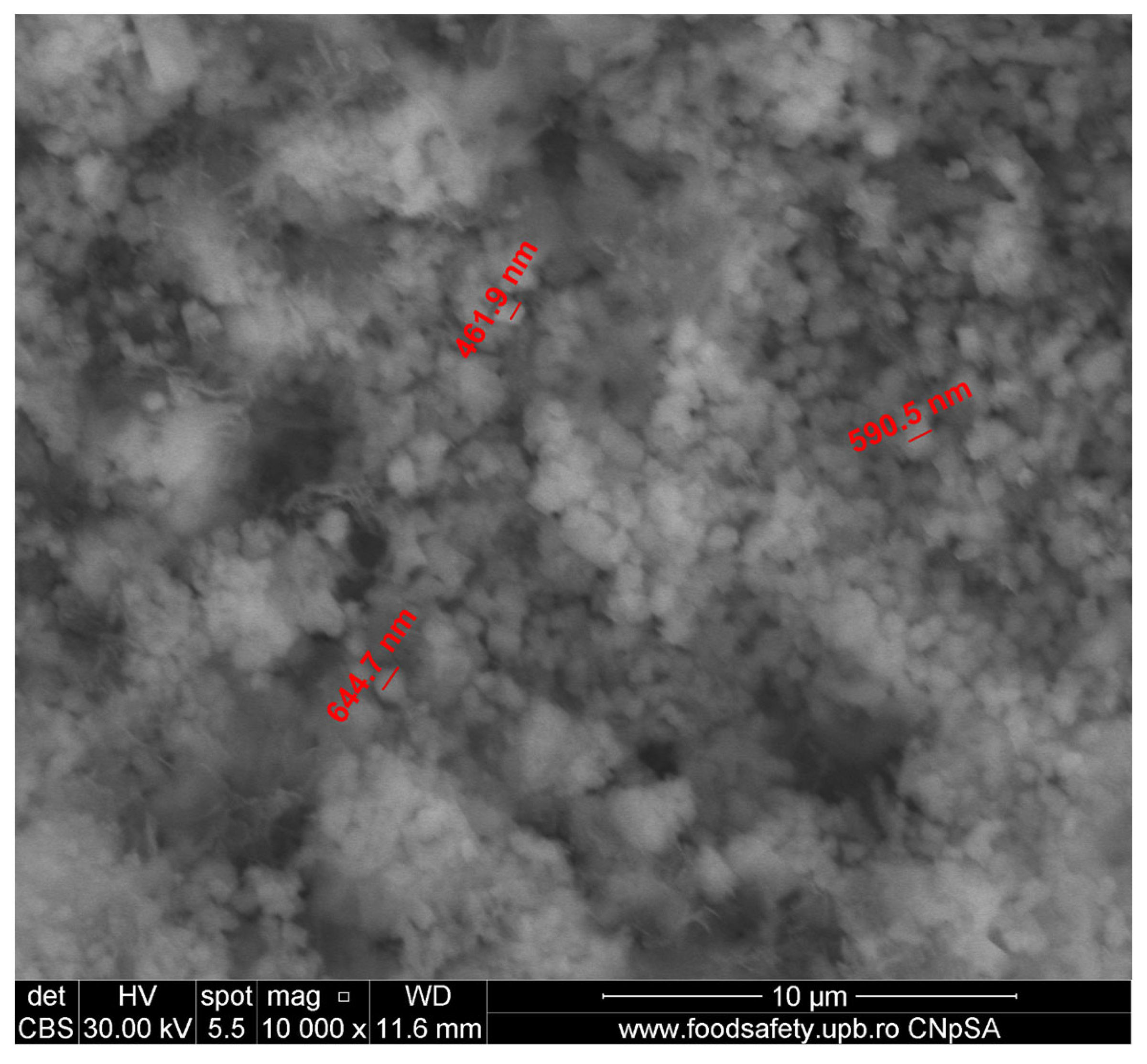
The submicronic, spherical, and uniformly sized CaCO
3 grains identifiable in
Figure 10 are most probably formed on a C-S(-H) bed (in atomic percentages: Ca—14.55, Si—2.09, Al—0.94). Their shape and size strongly contrast with the rest of the identified compacted, faceted-shaped, carbonate crystals, shown in
Figure 6; a possible explanation for the different morphology is that their source may not be the carbonation of Ca(OH)
2. Judging by the small size, a credible hypothesis could be that they were formed by the carbonation of hydrated compounds, such as in S3 C-S-H carbonation, thus providing a proof of carbonation depth [
12].
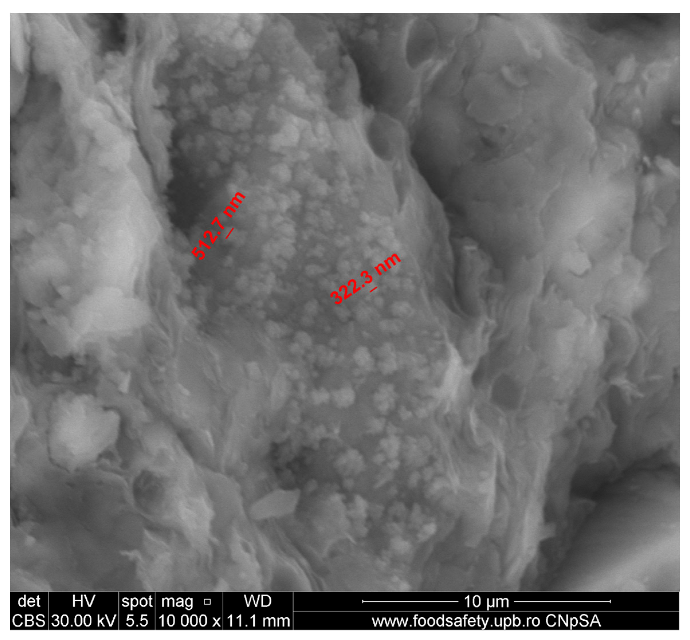
The same submicronic CaCO
3 lumps can also be found on the surface of the gneiss aggregate—
Figure 11.
From SEM-EDAX analysis, it appeared that the microstructure of the mortar is inhomogeneous and crossed by a developed network of cracks, channels, and interconnected pores. It shows areas developed in the entire mass of the sample of calcite, as a result of the mortar hardening in the masonry, but also areas of lumps, clearly defined, which can be isolated for further investigations. The latter were most likely formed by the carbonation over time of some ‘nests’ rich in slaked lime adherent to initial clusters of C-S-H/C-S-A-H hydrates. The two types of calcium carbonate/calcite, through the identified characteristics, come from the S2 pyrogenic calcite and S3 C-S-H carbonation calcite formation mechanisms, as presented in
Section 1. No evidence of S1 geogenic calcite could be found, although its presence cannot be completely excluded in the absence of additional analyses such as cathodoluminescence and thin sections [
33,
34].
Submillimeter-sized quartz grains were spotted, which, along with the identified albite and the visible biotite K(Mg,Fe)3(AlSi3O10)(F,OH)2, indicate an igneous origin of some of the fine aggregates. It is likely that locally available raw materials were used, because volcanic mountains are located at a few kilometers’ distance. The small size of the SiO2 grains could be due to (i) provenience, meaning that they may come from silt/other sediments (the hypothesis of fine grinding at that time could be rejected); (ii) larger grains having interacted with aluminosilicates via pozzolanic reactions, thus diminishing in size. Both hypotheses are equally probable.
3.3. ATR-FTIR Results
FTIR analysis, given in
Figure 12, was performed in two areas: the first was a white area (red curve) and the second a grey area of the matrix (blue curve). Both curves have absorbance peaks at the same position; what differs is their band intensity ratio. For example, peaks at 1418, 873, and 711 cm
−1, respectively, can be attributed to calcite and have a higher amplitude for white areas (red curve), confirming that these areas contain more CaCO
3 than the grey areas. A broad, asymmetric feature in the range of 1200–900 cm
−1 may indicate, with a high probability, the existence of albite feldspar, which was found in the XRD analysis (
Figure 4); however, many minerals that come from granite/gneiss rocks containing Si-O (biotite, quartz) or kaolinite could be found in that area. The 520 and 441 cm
−1 peaks identify the presence of quartz (or Si-O-Si in other minerals) in similar concentrations in the two samples. The broad band peaking at 3391 cm
−1 is related to the existence of -OH groups; this may indicate the presence of adsorbed water and is directly related to the observed high porosity. This band will mask the peaks of the hydroxyl groups in biotite or kaolinite. No evidence of calcium hydroxide (CH) could be found, even in the ATR mode (CH could be identified by its sharp peak at 3640 cm
−1), as its signal can be hidden if the CH concentration is low enough.
Previous literature data [
19,
35] were used to identify functional groups like CO
32− and Si-O and their characteristic FTIR peaks.
Differentiation between anthropogenic (pyrogenic) and geogenic CaCO
3 can be achieved using Fourier-transform infrared spectroscopy (FTIR) and the luminescence properties of calcium carbonate [
36]. Both methods are based on different densities and distributions of atomic defects in the calcite crystal structure. In calcite, three major infrared absorption peaks are identified:
out-of-plane bending CO
32− (873 cm
−1),
asymmetric stretching CO
32− (1418 cm
−1), and
in-plane bending CO
32− (711 cm
−1). It was shown that the ratio between
and
bands’ intensities reflects the order of the calcite crystal structure [
37]. A high ratio is indicative of disorder in the crystal, i.e., the calcite is a pyrogenic, while at low values of the ratio (around 3), the calcite has a geogenic origin [
37].
The analysis of
Figure 12 according to the procedure given in [
37] confirmed, based on the values of the ratio of the infrared absorption peaks,
for lumps and
for grey areas (binder), that the origin of the calcite in the examined specimens is pyrogenic, highlighting the absence of S1 geogenic calcite. A higher value ratio for lumps suggests this material to be radiocarbon dated.
To confirm the existence of biotite, FTIR microscopy and maps were recorded. The red cross is placed, in
Figure 13a, on the dark particle of about 0.5 mm size. FTIR maps corresponding to Si-O-Si groups and Al-O-Si groups, corroborated by the color, indicate that the particle is most likely made of biotite.
Figure 13b shows an FTIR map plotted at 1005 cm
−1, corresponding to Si-O-Si groups, which could indicate biotite, having the highest absorbance in the area of the particle.
Figure 13c gives the FTIR map recorded at 728 cm
−1, corresponding to Al-O-Si groups, which could indicate biotite, showing the highest absorbance in the area of the particle.
Note that the larger, white particle to its right side responds similarly, although weaker, indicating that is most probably made of albite.
FTIR-ATR analysis highlighted the structure of the compounds in the two areas. Calcite was identified both in the mortar binder and in the lumps. Its noticeably higher concentration in the lumps confirmed the previous results. What this investigation adds is the identification of biotite and the confirmation of the XRD results on kaolinite, quartz, and albite. They were identified in lumps, as impurities, along with calcite, partially explaining the lower %C percent determined in the EA.
If XRD and SEM-EDAX could disprove the hypothesis of lump-type formations originating from geogenic calcite (mechanism S1), FTIR-ATR draws attention to the fact that the CaCO3 from C-S-H carbonation, controlled by a depth profile relationship, must be considered (mechanism S3). The lack of calcium hydroxide demonstrates that the S4 Ca(OH)2 recarbonation mechanism may be excluded.
3.4. Thermal Analysis Results
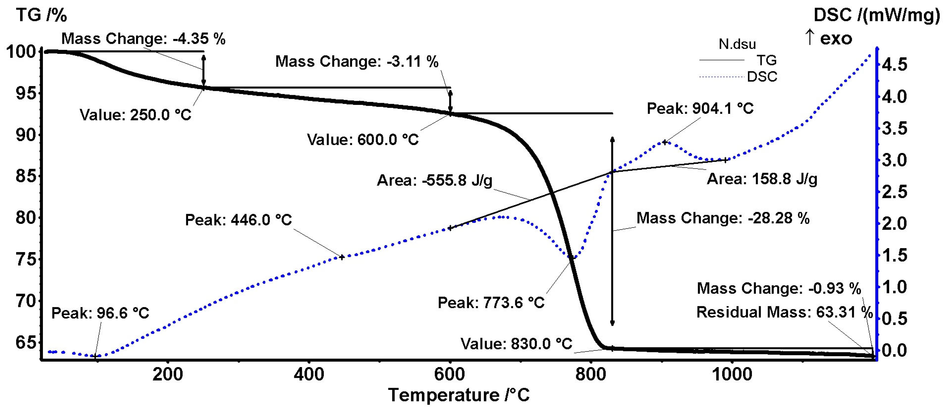
DSC-TGA analyses were performed on two samples, extracted from a white area (presumably with a higher concentration of calcite, denoted as N)—
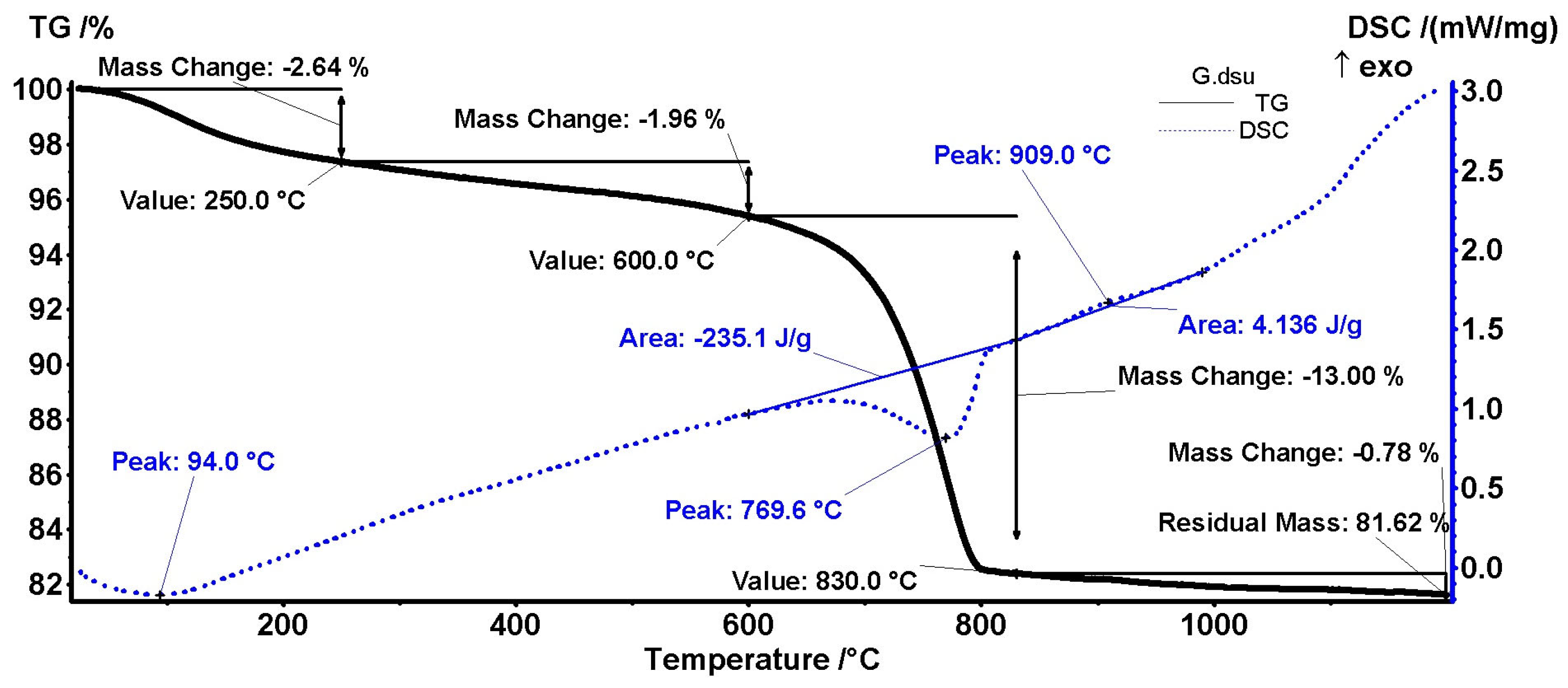
Figure 14—and from a grey area, denoted as G,
Figure 15. Both samples performed similarly at heating; however, the amplitude of mass changes and recorded enthalpies are different.
As can be seen in
Figure 14 for the white area (N sample, lumps), a first mass change occurs up to 250 °C (solid line for TGA) with a peak at 96.6 °C (dashed line for DSC). It corresponds to the elimination of adsorbed water, with the samples not being previously heated to 110 °C [
37]. The second mass change occurs up to 600 °C. It corresponds to dehydroxylation of clay minerals or C-S-H/C-S-A-H, which is related in the DSC diagram to the peak at 446 °C [
38]. No quartz transformation was identified at 573 °C, giving a sign of its absence in the lumps [
39].
The most important loss in weight of 28.28% was recorded in the range of 600–830 °C, with a peak at 773.6 °C. This could be attributed to the decarbonation of the calcite from lumps [
38]. Compared to the theoretical value of 43.97%, we found a percentage of around 64% calcium carbonate. A secondary peak was not identified at approx. 875 °C, generally associated with pure geogenic calcite or the polymorphic transformation of micaceous minerals, which is a sign of their absence [
38,
40]. An exothermic peak appears at around 904 °C and can be attributed to the final burning of organic wastes [
41].
Concerning the grey area (
Figure 15, G sample, mortar), the same losses at 94 °C, and up to 250 °C, can be found. Instead, the signal from approx. 446 °C disappeared. No quartz transformation was identified at 573 °C.
As for the decomposition of carbonates in the range of 600–830 °C, it is observed that this occurs at 769.9 °C. The dissociation temperature will depend primarily on their mineralogical structure, and also on the type and amount of impurities. Increasing the total content of aluminum, silicon, and iron oxides will lead to a decrease in the decomposition temperature, as a result of the formation of solid, unsaturated solutions in CaCO
3 [
38]. Compared to the theoretical value of 43.97%, we found a percentage of around 30% calcium carbonate, with possible different origins. A secondary peak was not identified at approx. 875 °C. An exothermic peak appeared at around 909 °C [
40].
As presented above, from the values recorded in
Figure 14 and
Figure 15 (13% for G sample and 28% in N sample), the CaCO
3 concentration can be obtained: ~29% for G sample (grey area) and 64% for N sample, i.e., in white areas, confirming the XRD (
Figure 4) and EA results.
A phase transformation can also be connected with lumps, at 446 °C, corresponding to the dehydroxylation of clay minerals or C-S-H/C-S-A-H. It does not show a phase transformation for quartz. The most important transformation is given in the range of 600–830 °C and is characteristic of calcium carbonate decomposition. Decomposition at a lower temperature in the mortar in comparison with lumps shows a greater ‘flux’ contribution of some mineral compounds. Geogenic calcite was not identified in this way either.
3.5. High-Resolution Gamma Spectrometric Analysis for Natural Radionuclides
The activity concentrations measured by gamma ray spectrometry in 80 g of mortar sample from Ulpia Traiana were 40K: 581 ± 12 Bq∙kg−1; 232Th (228Ac): 28.5 ± 2.8 Bq∙kg−1; and 226Ra: 32.7 ± 1.7 Bq∙kg−1, respectively. To verify the direct exposure to environmental factors, the existence of radioactive deposits of 137Cs (T½ ≅ 30 years), in the last 75 years, was checked. The level was, after 4.2 days of measurements, below the detection limit, i.e., below 0.77 Bq∙kg−1.
According to the distribution map, for the
137Cs inventory in this region (corresponding to May 1986, recalculated in 1993, 2016, and 2016–2018 from experimental data) [
42], a value of 5 ÷ 10 kBq∙sqm
−1 or greater was expected to be found. The obtained value, within the limits of detection, may be a sign of indirect exposure or rather of a continuous wash-up by water, humidity, and wind. This analysis opens up a new direction for future exploration of the ruins of ancient fortresses, offering the opportunity to establish whether or not the investigated areas were exposed to external factors after 1945.
Concerning naturally occurring radionuclides (NORs), these values reveal low activity concentrations due to the low content in local limestone [
43] or due to the specificity of other raw material sources in the area. This was the case for Bârzava (Romania), which afforded
40K: 514 ± 21 Bq∙kg
−1;
232Th (
228Ac): 49 ± 4 Bq∙kg
−1; and
226Ra: 38 ± 8 Bq∙kg
−1 (less than 100 km away), and for Eastern Hungary:
40K: 418 Bq∙kg
−1;
232Th (
228Ac): 32 Bq∙kg
−1; and
226Ra: 30 Bq∙kg
−1 [
44,
45]. The measured values for Ulpia Traiana were slightly lower than the average specific activity for Romania, which was
40K: 635 Bq∙kg
−1;
232Th (
228Ac): 46 Bq∙kg
−1; and
226Ra: 54 Bq∙kg
−1 [
46]. What was distinct for the above-mentioned locations was the ratio greater than 1 between
232Th (
228Ac) and
226Ra, revealing the materials used at Ulpia Traiana as being local materials. Volcanic tuffs or pozzolanic materials from the Roman Magmatic Province for enhancing the mortar’s mechanical properties were not involved [
47,
48]. The findings from the other analyses, i.e., showing that local materials were used, were in this way substantiated.
3.6. Radiocarbon Dating
Considering all the interpretations of the previous analyses, a procedure for extracting small portions of lumps (a white material with the apparent consistency of calcite) under a microscope was followed. The total sample came from multiple sub-samples at several points in the material. After homogenization, we proceeded according to
Section 2.2.
The calibration of the radiocarbon date (histogram) using the CHS method is presented in
Figure 16.
Based on the results obtained using the CHS, the age period falls within calAD 662–822, with a confidence level of 95.4%. In the CHS, only CO2 from inorganic materials is released.
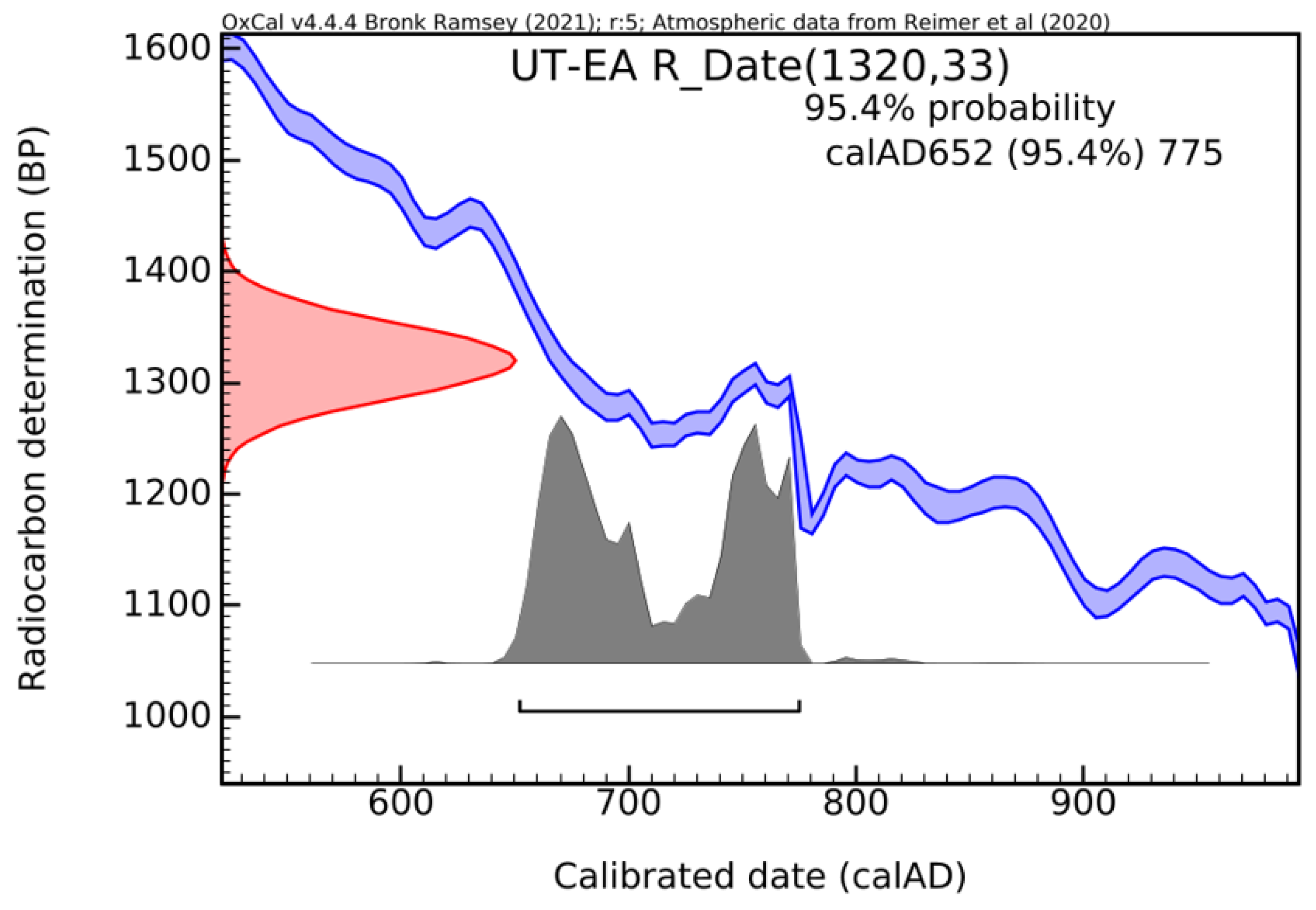
To verify the consistency of the radiocarbon date, a second round of dating was performed using the EA. In this case, without a prior pre-treatment of the samples, a radiocarbon date was obtained for all the forms in which carbon-14 is present (bio/organic and bio/inorganic). The second calibrated radiocarbon date is shown in
Figure 17.
This time, the age period falls within calAD 652–775, with a confidence level of 95.4%.
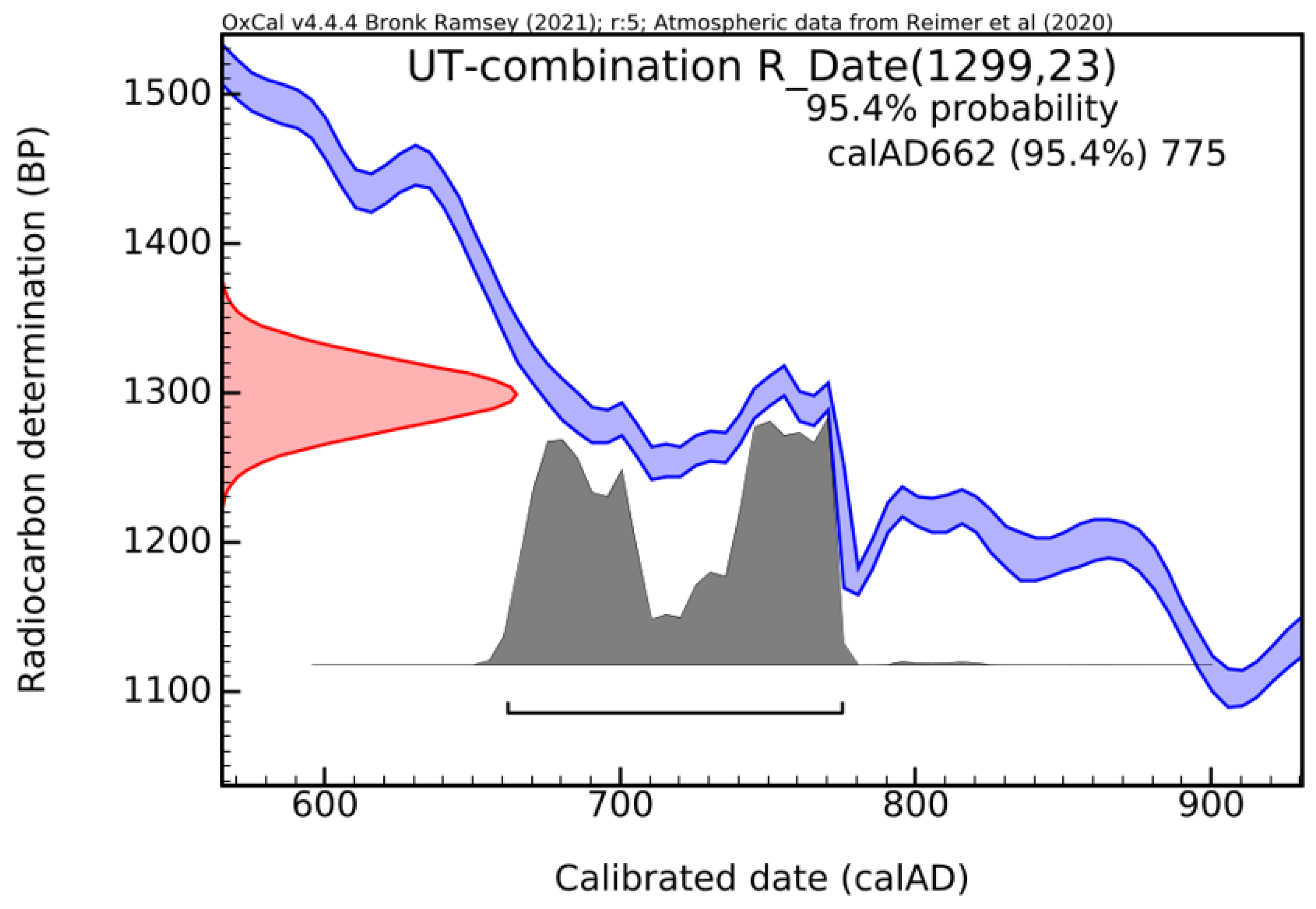
Both methods offered consistent results, reinforcing the reliability and accuracy of the dating outcome. Combining the CRA values by using the R_Combine function in OxCal [
29] demonstrates the ‘contemporaneity’ of the samples. The most likely interval becomes narrower, namely between calAD 662 and 775 (
Figure 18). The difference of approximately 100 years (within the limits of measurement errors) places it in the interval of 100–200 years, acceptable for the hardening of mortar in masonry.
The radiocarbon results confirm that it is not a modern intervention/late repair. The position of the sampling point excludes lateral contact producing C-14 exchanges during the lifetime of the monument [
49], sustained by previous analyses. So, it may represent a real age, but not one supported by the archaeological or historical information accepted until now, even if 100–150 years are added (see above). It is most likely an apparent age depending on the distance from the surface, denoted by S2 pyrogenic calcite and S3 C-S-H carbonation mechanisms, as explained in
Section 1. CaCO
3 from carbonated C-S-H/C-S-A-H, which could take up an unknown number of years, may be taken into consideration, if the degree of carbonation of the material is controlled by the carbonation depth (mechanism S3) [
12]. As presented in the literature, the phenomenon of delayed mortar hardening is common to these water-resistant materials, leading to apparent ages more recent than its application in masonry [
50]. Nowadays, similar materials in the cement class also exhibit this phenomenon. To modify the hardening period, retarders or accelerators, such as calcium lignosulfonate or sodium gluconate, are added [
50,
51].
Support for an apparently rejuvenated age or apparently obsolete one is given by the interpretations of the results obtained with the other investigation methods. The absence of geogenic calcite excludes the S1 mechanism stated in
Section 1. A mortar hardened in 100–200 years (given the sampling position, from inside the plinth) and rejuvenated (through surface exposure after the statue reached the ruin phase) cannot be taken into consideration (mechanism S4 Ca(OH)
2 recarbonation).
4. Discussion
The integration of the results from
Section 3.1,
Section 3.2,
Section 3.3,
Section 3.4,
Section 3.5 and
Section 3.6 involves two directions: firstly, the material characterization and the ageing processes undergone, and secondly, to what extent the information confirms carbonation during hardening or if secondary/subsequent recrystallization has taken place over time, leading to rejuvenation. When S2 pyrogenic calcite and S3 C-S-H carbonation mechanisms overlap, as is the case, it cannot be a matter of rejuvenation but of a delay in the mortar hardening. Calcium carbonate in lumps was not formed exclusively by the S2 pyrogenic calcite mechanism, from the excess of slaked lime, but also by carbonation into the ‘nested’ hydrated forms of calcium silicates/aluminosilicates (mechanism S3). If C-S-H are present and then it is a hydraulic mortar, there are high chances that the carbonation process took a long time, making the radiocarbon date unreliable. Such assumptions on the presence/absence of possible geological calcium carbonate, unreacted lime lumps, as well a tendency of calcium carbonate to dissolve and reprecipitate with younger environmental carbon can be verified later using high-resolution instrumentation such as cathodoluminescence (CL) [
33]. Also, optically stimulated luminescence (OSL) can be used to verify the correct choice of datable submicronic fractions [
52].
Radiocarbon dating places the use of this mortar in the Medieval times (Middle Ages, 7–9th centuries, more precisely), which is several centuries after Aurelian’s withdrawal from the Dacian provinces (271–272 AD).
If the radiocarbon date of the mortar taken from the plinth of the central statue in Forum Vetus had coincided with the time of its erection, i.e., 2nd century AD, the research would have been limited to characterizing the material (and obtaining a possible manufacturing formulation). In fact, the exact moment of construction is unknown but, the Trajan’s forum was finished, according to an inscription, around 110 AD [
53]. In the following period, a series of interventions were carried out in Forum Vetus, with the replacement of the cover limestone with marble, but there is no record of any work on Trajan’s statue. After 153 AD, it was extended by Forum Novum [
54]. The year 255 AD marks the retreat of the Huns with the abandonment and degradation of the colony. Thus, the construction of the plinth of the statue initially attributed to Trajan can be included in this period of approx. 150 years. The difference of centuries compared to the radiocarbon date, given that there were no modern interventions on this architectural element until now, raises new challenges, both technical and historical.
If the age is correctly represented by the radiocarbon date, there are two hypotheses: (i) a temporarily return of the Romans in the site, in which case the mortar is a Roman mortar, made with pozzolanic materials transported from the Italic Peninsula; (ii) resident craftsmen, either indigenous or migratory, possessed the knowledge and skills to develop lime mortars with locally available materials as in the case of basilica Torre de Palma [
3]. Both hypotheses should be treated with caution, as there is not yet available evidence of any kind to support them.
If the age is ‘apparent’, beyond the threshold of 100–200 years generally accepted by the literature, the phenomenon of rejuvenation/delaying of the mortar hardening must be taken into account. Other hypotheses appear: (i) the sample was taken from the inner area of the plinth below the surface of the remaining part of the construction, leading to a slow exchange of the carbon-14 isotopic signature (thus modifying the radiocarbon date by the imminent contact with atmospheric CO
2; it is brought by meteoric waters or by organic and inorganic compounds in the air or water, of younger ages over time, as suggested by radiometric analyses) [
55]; (ii) another hypothesis must take into account which hinges on the degree of carbonation with depth in the case of cementitious materials, commented on above.
Although a direct ‘rejuvenation’ of an older material with a younger C-14 (based on S1–S5 sources) is the most common hypothesis, a third one cannot be excluded: (iii) the mortar belongs to the time period of the return of the Romans, in the 10–13th centuries. The Medieval reuse of ancient ruins was a generalized phenomenon in the territory of the former Empire. Not far from Sarmizegetusa, at Alba Iulia, it was established that the walls of the castle were fully reused for a Medieval fortress until the 13th century. Some towers were in operation even in the 14th century. Roman ruins can still be seen there, included in the structure of the palace of the Roman Catholic bishopric, together with numerous archaeological vestiges [
56]. In fact, it is an ‘ageing’ that involves other directions of research: the slow exchange occurs this time between the same contaminating factors and geogenic sources of calcite (S1 geogenic calcite, S5 calcareous concretions) with an infinite radiocarbon age [
57].
5. Conclusions
A set of analyses were applied on an ancient lime-based, porous concrete (denoted as mortar) extracted from the central part of Trajan’s statue, Ulpia Traiana archaeological site, Romania.
This sample underwent complex characterization and we can offer the following conclusions, very useful in defining this ancient construction material:
Mainly albite, quartz, and calcium carbonate, along with kaolinite, were identified in XRD/SEM-EDAX performed on the binder matrix. Visible biotite grains of 1–2 mm in size were also observed, along with other aggregates (of various sizes and natures), all of them well-embedded in the binder matrix.
The ‘specimen’ surfaces and also fracture or fresh-cut surfaces contained white, up to millimeter-sized lumps made of more than 60% CaCO3. This carbonate may appear due to carbonation of Ca(OH)2 over time, generally within 100–200 years.
In addition, all surfaces, old or newly made by fracturing/cutting, were covered with a white, thin layer of carbonate, which appeared in SEM images as submicronic, spherical, and uniformly sized CaCO3 grains. The origin of this carbonate may be the carbonation of the possible C-S-H hydrates formed within the binder matrix; this process, depending on depth, may have taken place in over 400 years. The pozzolanic reaction is suspected, as very small grains of silica (less than 150 μm in size) were detected.
FTIR analysis confirmed the presence of all previously identified minerals and suggested, based on the values for the ratio of the infrared absorption peaks, for lumps and for binder, that the origin of the calcite in the examined specimens is pyrogenic (for reference, geogenic, natural calcite has a low ratio: ). No calcium hydroxide was found, proving the lack of secondary calcite, much younger, in the formation.
Gamma spectrometry offers a new option for investigating a monument’s dynamics, using 137Cs as a radiotracer for over the last 75 years. Naturally occurring radionuclides such as 40K, 232Th (228Ac), and 226Ra strengthen the hypothesis of using local materials and not of bringing volcanic ash or pozzolanic materials from Italy.
Certain information was useful for the selection of datable material, namely, the so-called lumps.
The history of this statue is well-documented, with its construction being placed in the 2nd century AD, so the radiocarbon date was surprising.
Radiocarbon dating placed the material within the calAD 662–775 interval, with a confidence level of 95.4%, although questions arise as to whether this is a real age or an apparent one. What should have been a routine analysis, supported by other investigations, has become a case study that shows the limitations of radiocarbon dating.
The analyses demonstrated that there is no geogenic calcite, that the mortar has reached maturity, and that there are no phenomena of decarbonation with recarbonation to secondary calcite (within the limits of detection of the methods used). The fragment taken from the center of the exposed surface, the calcite to be dated, comes from the carbonation of excess slaked lime interconnected with the carbonation of C-S-H hydrates. The latter process is time-dependent and governed by the distance from the outer surface, with the equilibrium being reached within hundreds of years. No organic remains were detected, which could lead to rejuvenation phenomena. In this case, the archaeological context and the evolution over time of the statue, which are well-known, could provide a starting point for better quantifying the phenomenon of delayed hardening of mortar over time.
Further laboratory investigations, such as analysis in thin sections, CL, or OSL, could provide additional arguments to validate the findings, especially serving to disprove the existence of secondary and geogenic calcite.


 ,
, 


