Article

High-Speed Kinetic Energy Storage System Development and ANSYS Analysis of Hybrid Multi-Layered Rotor Structure

by
Cenk Yangoz
1 and
Koray Erhan
2,*
1
Department of Mechanical Engineering, Istanbul Gedik University, Cumhuriyet, Ilkbahar Sk. No:1, Istanbul 34876, Turkey
2
Department of Mechatronics Engineering, Marmara University, Maltepe Yerleskesi T2 Blok, 2. Kat Aydinevler Mah. No:15, Istanbul 34854, Turkey
*
Author to whom correspondence should be addressed.
Appl. Sci. 2025, 15(10), 5759; https://doi.org/10.3390/app15105759
Submission received: 8 April 2025 / Revised: 19 May 2025 / Accepted: 19 May 2025 / Published: 21 May 2025

Abstract

:
Flywheel energy storage systems (FESSs) can reach much higher speeds with the development of technology. This is possible with the development of composite materials. In this context, a study is being carried out to increase the performance of the FESS, which is especially used in leading fields, such as electric power grids, the military, aviation, space and automotive. In this study, a flywheel design and analysis with a hybrid (multi-layered) rotor structure are carried out for situations, where the cost and weight are desired to be kept low despite high-speed requirements. The performance values of solid steel, solid titanium, and solid carbon composite flywheels are compared with flywheels made of different thicknesses of carbon composite on steel and different thicknesses of carbon composite materials on titanium. This study reveals that wrapping carbon composite material around metal in varying thicknesses led to an increase of approximately 10–46% in the maximum rotational velocity of the flywheel. Consequently, despite a 33–42% reduction in system mass and constant system volume, the stored energy was enhanced by 10–23%. It was determined that the energy density of the carbon-layered FESS increased by 100% for the steel core and by 65% for the titanium core.

1. Introduction

The need for energy storage is increasing with technological developments. Energy storage can be classified as small, medium and large scale. There are many energy storage solutions, from consumer electronics to supporting the electrical grid. The most commonly used energy storage technologies are battery energy storage (BES), ultracapacitor energy storage (UESS) and flywheel energy storage (FESS) [1,2]. Each of these storage technologies has its own areas of use, advantages and disadvantages. When choosing the storage technology to be used, parameters, such as system life, cost, energy density, power density, safety, performance, cycle life, and maximum system power, are taken into consideration. When FESS is examined structurally, it stands out with parameters, such as low maintenance cost, high power density, high cycle life, and long system life [1,2]. When the studies are examined, it is seen that FESS is preferred, especially in the fields of space and aviation, military technologies, electric and hybrid electric vehicle (HEV) applications [3], renewable energy production facilities, grid-based energy storage systems, and distributed energy production systems.
FESS, which works in parallel to BES in electric vehicles, is used for the storage of regenerative braking energy. For short-term high-energy transfers, kinetic energy storage systems are more advantageous than batteries. In addition, hybrid storage reduces the electrical stress on the system [4]. FESS has been preferred by NASA for many years in space applications. The most important reasons for this are its long service life, durability and wide operating temperature range. For similar reasons, it is also preferred in military applications. In addition, the increasing utilization of renewable energy sources has made FESS a compelling and appealing option for both implementation and further investigation. The main reason for this is that renewable energy sources have an intermittent energy production profile [1,5]. Storage technologies compensate for this intermittent situation in energy production and enable a continuous and balanced energy output. FESS is a significant technology that regulates wind-related speed fluctuations, especially in wind power plants. Energy storage systems play an important role in distributed generation areas where there is no electricity grid and in order to perform the load shift operation required for peak demand management in the grid [6,7]. It is emphasized that FESS is a storage system that increases power quality when used in a grid-connected manner [8]. Grid-connected FESS units are used as commercial products for over 10 years, in large-scale power stations in the USA, to compensate for events such as instantaneous voltage drops, voltage spikes, short-term interruptions and black-outs, which occur in the electrical grid and deteriorate power quality [2]. In this context, in 2024, China commissioned a 30 MW FESS energy storage power plant called the Dinglun flywheel energy storage power station in Shanxi province. Thus, China broke the record of the 20 MW FESS storage plant located in Stephentown, New York, belonging to the American company Beacon Power [9].
FESS works on the principle of kinetic energy storage on a rotating mass [10]. Although it is an industrial technology that has been used for over a century, today, the development of manufacturing technologies and materials science has made it possible to produce high-speed energy storage systems. In the last 50 years, high-speed FESSs have increased from 7000 RPM to 400,000 RPM. In addition, energy and power density values have increased by more than 10-times [2,11]. Despite the increase in speed and stored energy, there has been a decrease in system weight. The most important parameter that allows for the decrease in system weight is the new-generation composite materials used in the rotor [12,13,14,15,16]. Carbon fiber or glass fiber materials with higher tensile strength than steel and titanium are preferred in high-speed FESSs. Metal rotor structures and composite rotor structures are completely different in terms of design, analysis and production. The rotor is formed by bonding composite materials in layers or winding them in the form of yarn [12,13,14,15,16]. The design phase should take into account the effect of the rotor material on the manufacturing process. Composite materials have uncertainties at the micro level. Therefore, reasonable safety factors should be selected, and reliable detection methods should be used. Generally, composite materials have higher specific strength than metal materials, but metal materials are isotropic, so theoretically they can be made into a constant stress disc. Composite materials are orthotropic, so they never have the shape of a constant stress disc. However, composite materials are more expensive than metal alloys. The decreasing price of lithium batteries over the years has put pressure on the unit cost of FESS [17]. Studies report that the production cost per unit power is between USD 600 and USD 2400/kW, and the operation and maintenance costs are around USD 5.5/kW year [17]. It is reported that a FESS with a nominal power of 250 kW costs between USD 250 and USD 350/kW, and the corresponding unit energy cost is between USD 1000 and USD 5000/kWh [18]. The International Renewable Energy Agency estimates that the unit energy cost of FESS will decrease by 35% by 2030 [17].
In this study, the effects of different materials on the energy storage capacity of the flywheel and the maximum speed that the rotor can reach are simulated with the finite element analysis program (ANSYS 2019 R3 v19.5). In the literature, multi-rim flywheel structures have been realized for steel, aluminum and carbon fiber [19]. In some studies, structures up to seven layers have been obtained by wrapping carbon fiber layers with metal strips. However, here, the metal layer is used only as a binding intermediate material [14]. In the study, 11 variations with the same rotor dimensions but different layer thicknesses are compared with each other. While steel is preferred for bearing housings and inner rotor material in the literature, titanium material is also analyzed in this study in addition to the steel shaft. The thickness of the outer-layer composite material is kept variable, and the effect of the thickness change on the maximum speed is observed. Layered structures are also compared with monolithic (steel, titanium and carbon composite) rotors, and the advantages and disadvantages of the multi-layer structure compared to the monolithic structure are determined. In the structures examined within the scope of this study, both the metal inner core and the composite outer layer store energy.

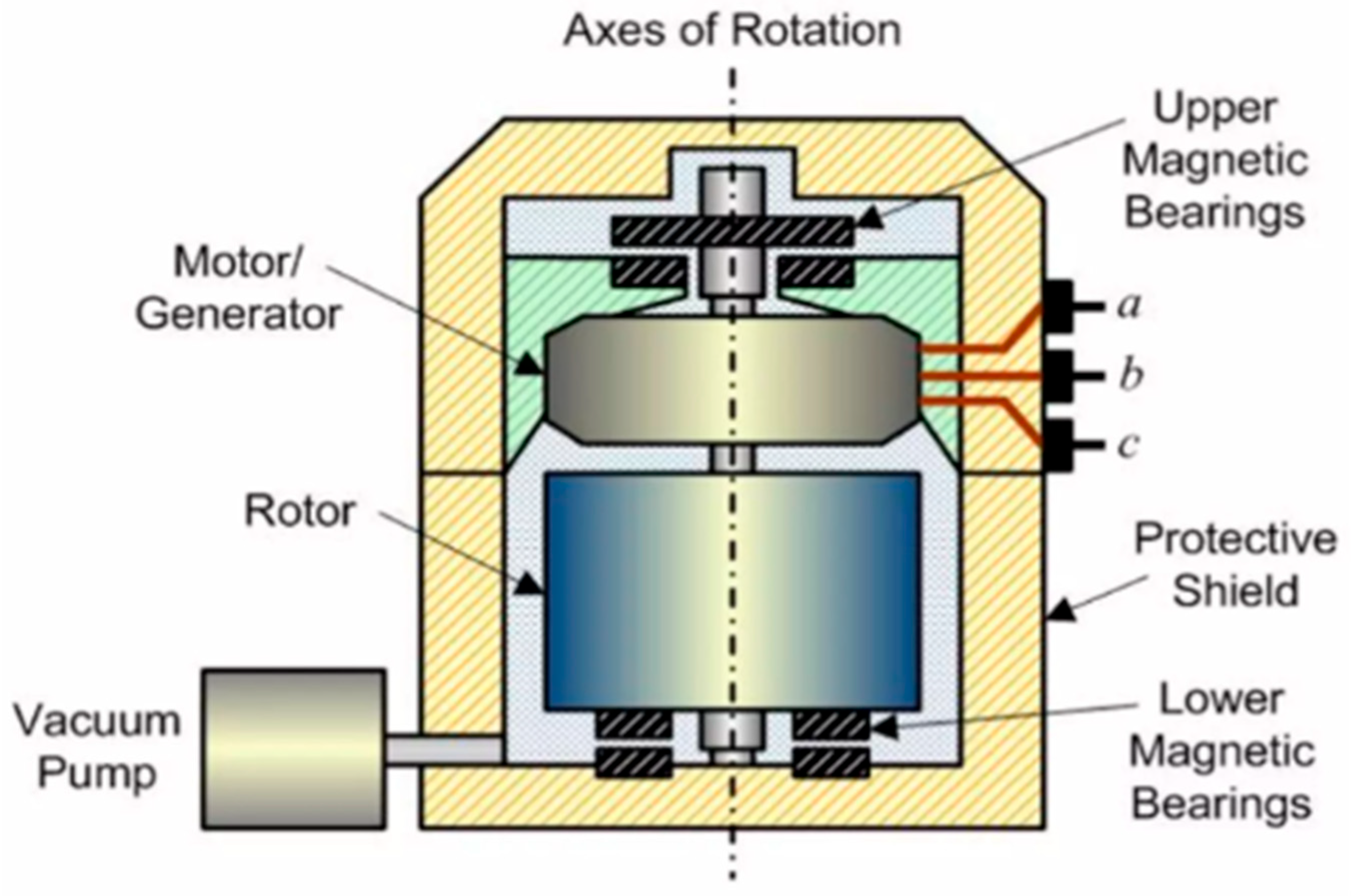
2. Design Parameters of Flywheel Energy Storage System

The flywheel system works on the principle of storing kinetic energy on a mass rotating at high speeds. Thanks to the rotor gaining speed, the rotating mass gains kinetic energy, and the aim is to preserve this energy for as long as possible. Figure 1 shows the general structure and components of the flywheel energy storage system [20]. FESS consists of a rotor mass, a motor/generator, a closed, protective outer body and bearings. The system is vacuumed to prevent air friction at high speeds and the resulting turbulence.

2.1. Energy and Power Parameters

In automotive applications, both volume and weight limitations are critical constraints. Therefore, the rotor diameter of FESS units designed for automobiles typically does not exceed 30 cm [4]. In tramway and bus applications, the rotor diameter can extend up to 40–50 cm. The restriction on rotor diameter necessitates an increase in rotational speed. For automotive-specific applications, rotor speeds generally range between 50,000 and 80,000 RPM [2]. The first example of the use of FESS for regenerative braking in vehicles dates back to the time when the FIA began to allow the use of kinetic energy recovery systems in Formula 1 cars. Later, two F1 teams were licensed to use this system [21,22]. However, this system was not used effectively in the following years due to changing regulations. In the following years, Jaguar developed a KERS (kinetic energy recovery system)-based system for the XJ model vehicle. This vehicle also holds the title of being the first passenger sedan equipped with TOROTRAK. It is known that larger-scale versions of the system have been tested in public transport. It is claimed that the system provides an approximately 40 percent fuel efficiency improvement [23]. In the bus application in Figure 2, a FESS is integrated into the vehicle powertrain for regenerative braking.
Considering the combined constraints of rotor diameter, speed, and weight, a carbon composite can be selected as the rotor material [11]. The rotor is fabricated through the filament winding of carbon fibers in successive layers, each of which is bonded with epoxy resin. Thus, the overall mass of the rotor remains below 30 kg [4].
In grid-scale energy storage systems, the rotor mass can reach up to 300 kg. For these applications, the rotational speed is limited to approximately 30,000 RPM [11]. In stationary applications, where mass is not a critical constraint and rotational speeds are comparatively lower, steel is often preferred as the rotor material. The magnitude of the stored energy is directly proportional to the weight of the rotor mass. FESS power plants are connected to the grid in parallel to avoid blackouts. There have been numerous FESS facilities operating in various regions of America since 2011. The installed power of these facilities is over 60 MW. Similarly, Canada established a storage facility in 2014 [24].
Another approach to enhance the stored energy is to increase the rotational speed rather than the rotor mass. Because the stored energy increases proportionally to the square of the rotation speed, the production of this type of high-speed FESS requires advanced technology. Considering its usage areas, it is generally seen in space and aviation, electric vehicle (EV) and defense industry applications. Equation (1) represents the stored energy in the flywheel energy storage unit. The formula represents the amount of stored kinetic energy ‘E’, the moment of inertia ‘J’, angular velocity ‘ω’, mass ‘m’, and rotor radius ‘r’.
E = 1 2 J ω 2
The moment of inertia depends on the rotor mass and geometry, as in Equation (2):
J = r 2 d m
The energy stored in the flywheel must be calculated by taking into account its mass and material properties. Based on the strength characteristics of the material used, it is possible to determine the maximum velocity of the rotor. Equation (3) provides the value for the rotor’s maximum angular velocity. In this equation, the following terms are defined:
  • ω is the angular velocity;
  • ro is the outer radius;
  • ri is the inner radius (0 for a solid disc);
  • ν is Poisson’s ratio;
  • ρ is the material density;
  • σt, max is the yield stress.
ω = 8   ·   σ t 3 + υ   ·   ρ   ·   ( r O 2 r I 2 )
Since FESS is used in a wide variety of areas, a precise framework cannot be drawn to determine its dimensions. More complex sizes and high-speed systems are used in mobile applications. The rotor material is generally composite components or titanium alloy. The volume of the systems preferred in areas such as automotive, aviation and space applications are generally between 1 and 50 L. Weights generally range from a few kg to a maximum of 100 kg. Rotation speeds vary between 10,000 and 400,000 RPM. However, larger masses and lower speeds are preferred in grid-based stationary applications requiring high energy storage capacity and high power. Electric grid support, regulators used in renewable energy generation systems, and UPS systems utilize FESS with rotor weights ranging from a few hundred kilograms to several tons. Rotational speeds vary between 5000 and 50,000 RPM [25,26].
FESS rotors are made from various materials. The properties of rotor materials, including their energy densities and mechanical strengths, are documented in Table 1 [17,27,28]. In experimental investigations, steel materials have been found to achieve rotor speeds of up to 50,000 revolutions per minute [10]. This value corresponds to 1500 km/h peripheral speed. At higher speeds, materials with higher mechanical strengths or composite materials are utilized. As the rotor attains high speeds, the centrifugal force increases, leading to excessive stress on the material. Materials unable to withstand centrifugal forces pose a risk due to the shrapnel effect caused by the fragmentation scattered around.
This study focuses primarily on the analysis of high-speed FESS using the ANSYS program. The aim is to investigate a rotor size suitable for mobile applications, with a diameter of 100 mm and a width of 40 mm. While keeping the rotor dimensions constant, maximum speeds achievable for different materials are determined. Additionally, the impact of multi-layered structures on the rotor is observed, and analysis studies are conducted for different systems.

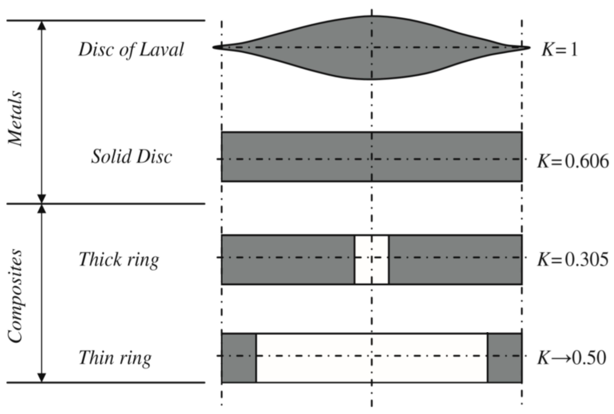
2.2. Structural Parameters and Material Selection

The FESS rotor can have different geometries. The most preferred of these structures is the solid cylindrical rotor. The moment of inertia of a solid cylindrical mass is half the moment of inertia of a hollow, circular rotor. However, since it can be easily balanced and the possibility of resonance, explosion and fragmentation at high speeds is low, the solid cylindrical rotor structure is generally preferred. The shape factor K is also a representation of material utilization. Figure 3 shows the “shape factors” of rotors with different geometries.
In this study, a solid cylindrical rotor structure is preferred as a design, and simulations are performed according to this geometry. In order for the system to reach high speeds, attention is also paid to the material selection. The preferred materials are manufacturing steel, titanium alloy and carbon fiber materials, and their hybrid structures are also being examined.
The material’s ability to withstand the centrifugal force exerted on it determines the maximum speed of the rotor. This is the ultimate strength of the material. There is a direct relationship between the mass, centrifugal forces, and radius, as well as the speed. Material selection is a very important stage in FESS design. The ideal materials for flywheels are lightweight and durable. This implies that the density of the material must be lower. For higher speeds, the material must also have high tensile strength. These characteristics are common with composite materials, unlike metals with higher weight, but the cost of metal is lower than that of composites. Composite materials are lightweight yet possess high strength values. These materials exhibit a high specific strength. Rotor speed and the desired energy value to be stored are directly related to the rotor material. The basic selection criteria to be considered here are the application in which the system will be used, the amount of energy to be stored and the total system cost. Within the scope of this study, two types of multi-layered hybrid rotor structures are considered (mild steel, carbon fiber and titanium alloy, carbon fiber) with three different basic materials (mild steel, titanium alloy, carbon fiber).

2.2.1. Mild Steel

Mild steel is the most commonly used material in production and is easier to process than other steels. The properties of mild steel are listed as follows:
Suitable yield point and tensile strength for many applications;
Suitable impact resistance;
Resistance to brittle fractures;
Good weldability;
Good formability;
Good machinability.
They are steels that contain low carbon content, non-alloyed phosphate (P) and nitrogen (N), manganese (Mn), silicon (Si), copper (Cu) and sulfur (S) elements originating from production raw materials and production methods; they are hot formed, normalized and sometimes cold drawn, especially considering their tensile strength and yield points, and are used in industrial and structural studies [30,31]. The structural properties of mild steel in the ANSYS program are shown in Table 2.

2.2.2. Titanium Alloy

Titanium is a light, high-strength, shiny, corrosion-resistant metal. Titanium can be alloyed with elements, such as iron, aluminum, vanadium, and molybdenum. This alloy, which has good strength and lightness, is used in military and many other areas (jet engines, missiles, spacecraft). The most important feature of titanium, a metallic element, is its strength/weight ratio. Pure titanium is completely flexible. Titanium (although not as hard as some heat-treated steels) is antimagnetic and a poor heat conductor. As a result of special processes, the room-temperature strength of titanium alloys can reach 1372–1666 MPa [32]. The structural properties of the titanium alloy used in the ANSYS program are given in Table 3. The yield and rupture stresses of this material are higher than mild steel; it is more durable and less dense.

2.2.3. Carbon Composite Material

Carbon composite is a material that emerged as a result of a 40-year development process. Carbon fiber, which finds its place in many areas, has been used in many sectors such as the automotive, aerospace and aviation sectors for many years. The most important feature of carbon fiber is that it is 4.5-times lighter and 3-times stronger than steel. Carbon, which is used in the chassis and many parts of sports cars, is shown to be the best material for producing lighter and more durable cars. The characteristics of this material are as follows [31,32]:
Low density;
Lightweight;
Corrosion resistance;
Easy production method;
Low coefficient of friction;
Can be considered high strength.
Areas where carbon fiber is used include the following:
Aviation sector;
Spacecraft;
Automotive;
Maritime;
Industrial equipment.
Carbon fiber materials have different properties depending on the raw material and production method. These properties are taken into consideration when classifying. In the production of carbon fiber, it is formed by combining orlon, nylon, tar and other chemicals. Carbon fiber requires chemical and mechanical processes to form. The precursor is drawn into long wires or fibers and then heated to a very high temperature by cutting off contact with oxygen. Since there is no oxygen, the risk of burning the fiber is eliminated. High temperature allows most of the atoms in the carbon to be expelled, allowing the atoms in the fiber to vibrate violently. This process is called carbonization. At the end of the process, a long, dense fiber structure is obtained. Carbon fiber is a specially produced material that can withstand very high stress. It is a very light material due to its low density. The properties of the carbon fiber material used in the simulations are given in Table 4.
There are various techniques for coating composite material onto a metal core, including epoxy resin bonding, high-temperature molding, filament winding with composite ropes, and roll-form composite woven fabric wrapping. The primary criteria that determine the appropriate method include maximum peripheral speed, rotor dimensions, rotor mass, the G-force the system will be subjected to, and the type of application (mobile or stationary).
It is well known that high-speed hybrid flywheels are particularly sensitive to temperature fluctuations. This sensitivity arises from the difference in thermal expansion coefficients between the metal core and the composite material wrapped around it. Consequently, temperature control is crucial in hybrid flywheel systems. As the system deviates further from its initial manufacturing temperature, the risks of rotor imbalance and layer delamination increase substantially [33,34,35,36].

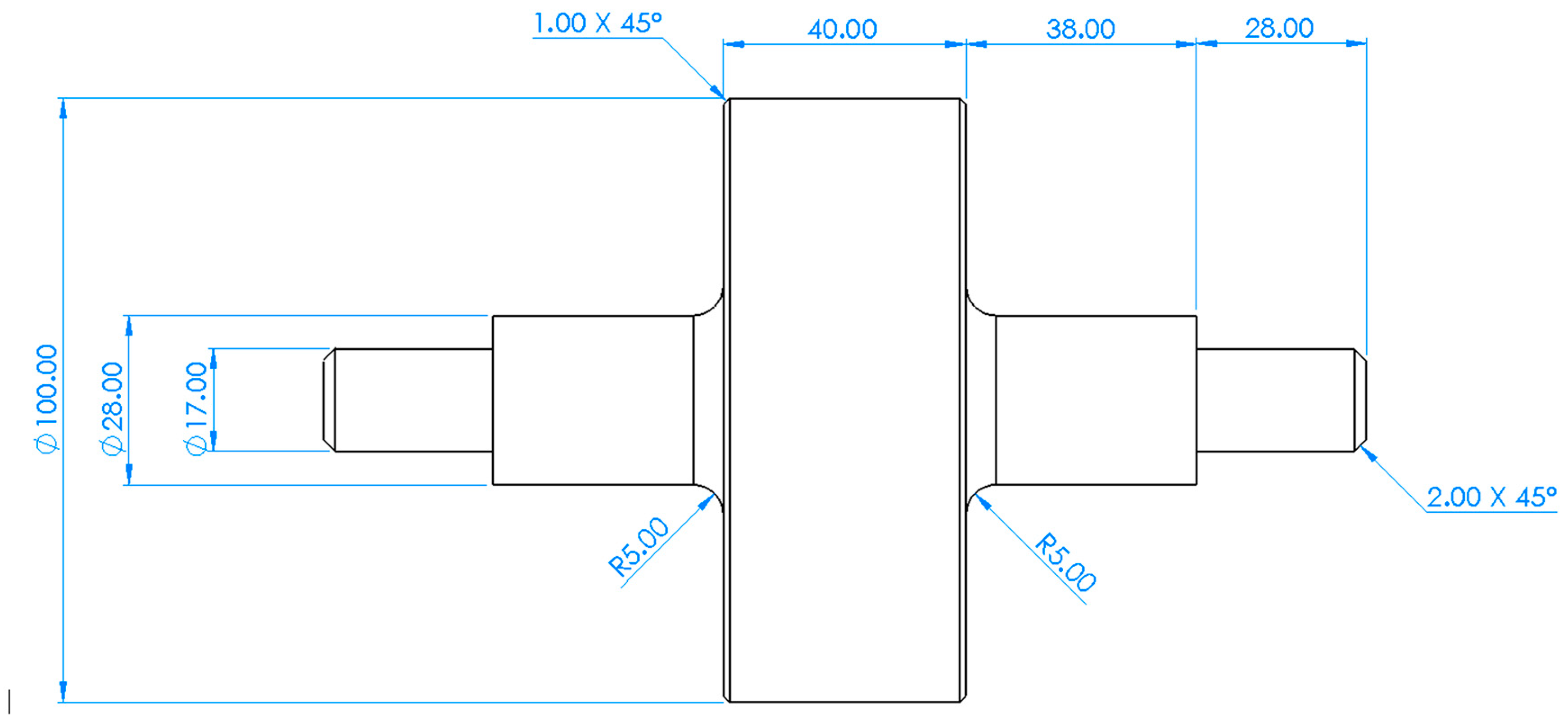
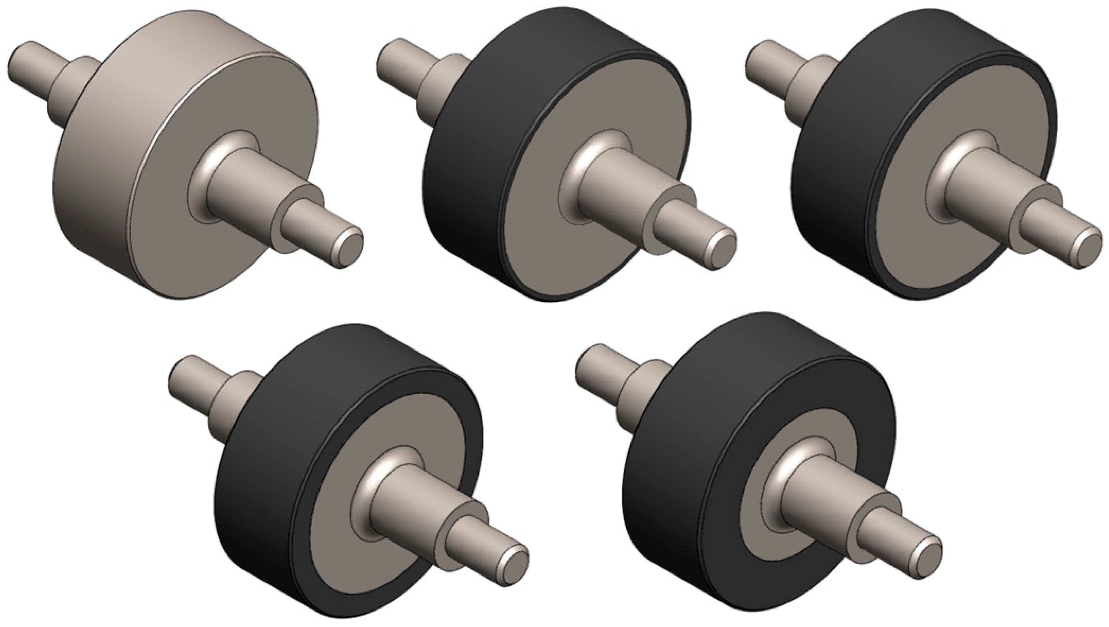
2.3. Rotor Design and Specifications for Simulation

The flywheel design is created using the Solidworks program (2023 SP5.0), employing two different dimensional approaches. The flywheel has an outer diameter of 100 mm, with a width of 40 mm. The technical drawing is given in Figure 4. To reduce mechanical stresses, chamfering processes are applied to sharp corners. In the prepared design, for the multi-layered rotor structure, the thicknesses of the top layers are determined as 3 mm, 5 mm, 10 mm, and 20 mm. A bearing seat with a diameter of 17 mm and a location for the bearing inner race to rest, with a diameter of 28 mm, were designed for mounting purposes. Considering the FESS dimensions, the total length is 172 mm.

2.4. Performing Program Settings for Simulations

Mesh selection is an essential criterion for obtaining more efficient analysis outputs during analysis. Mesh quality is affected by many factors of the analysis. As the number of mesh nodes and elements affecting the mesh duration increases, analysis durations increase. It is known in the literature that quality is good when the skewness value is below 0.9 [37,38,39,40]. In this application, the skewness value indicating mesh quality was obtained as 0.76092.
The method selected to increase mesh quality is the MultiZone method. The MultiZone method is generally applied to cylindrical parts, allowing each element of the cylinder to be created equally. Since each element is created equally and in the same geometry, it reduces the skewness value. The flywheel rotation center is selected. The center is obtained by selecting the surfaces of the largest outer diameter in ANSYS Rotational Velocity [37,38,39,40].
When determining the maximum speed, the static properties of the selected materials are taken into account. The elastic zone limit and the ultimate tensile strength values are taken as limit points. Tensile test data were examined to determine the maximum values of the stress. The maximum value that the system can reach without breaking after passing into the elastic zone is simulated by the program.

2.5. Analysis Findings and Interpretation

The analysis study is examined in two stages. Firstly, the analysis results are obtained based on the data of the Y region, which is the region where the material starts to flow, and, secondly, the data of the U region, which is the rupture region. The materials whose properties are given in Table 5 are manufacturing steel, titanium alloy, and carbon fiber-reinforced polymer (CFRP), respectively. The yield point data for the Y region, which is the yield limit of these materials, are 250 MPa for manufacturing steel, 930 MPa for titanium alloy, and 23 GPa for CFRP. The U zone values for the rupture point are 460 MPa for manufacturing steel, 1070 MPa for titanium alloy and 23 GPa for CFRP. Since there is no yield point for carbon fiber material, yield and breaking point data are the same.
In the analysis, the maximum RPM that can be reached is calculated based on the yield and rupture point stress values of each material. The analyses are performed first for the Ø100 diameter rotor and solid material. Then, in the hybrid design, the analyses are repeated for 3 mm, 5 mm, 10 mm, and 20 mm CFRP-layered structures. Figure 5 shows hybrid rotor structures with metal-inside and composite-outside multi-layers for different thicknesses. According to the analysis results, the region subjected to maximum stress is shared in the figures. The equivalent (von-Mises) stress method is used to determine whether the flywheel has undergone plastic deformation.

3. ANSYS Analyses Results

In this study, multiple materials with different layer thicknesses were analyzed using a finite element analysis (FEA) program. Although the system could also be evaluated using an analytical calculation method instead of FEA, the multi-layered structure and the use of materials with varying technical properties make such calculations time-consuming. When using FEA, changes in parameters can be implemented much more rapidly. In contrast, analytical methods require complete recalculation and re-iteration from the beginning for any change in a single parameter. From this perspective, FEA offers a significantly more practical and efficient approach. Analysis outputs were obtained using materials selected from the ANSYS library. While determining the boundary conditions of the model, “body-ground joint” is defined in the regions where there are bearings, and it was assumed that these regions only allowed for rotation on the Z axis and movements on other axes are neglected. This approach aims to better represent real operating conditions. In addition, the accuracy of the analysis results is increased by giving the rotation speed to the flywheel from the region where the maximum stress will occur. In this way, a more realistic and reliable structural analysis can be obtained.

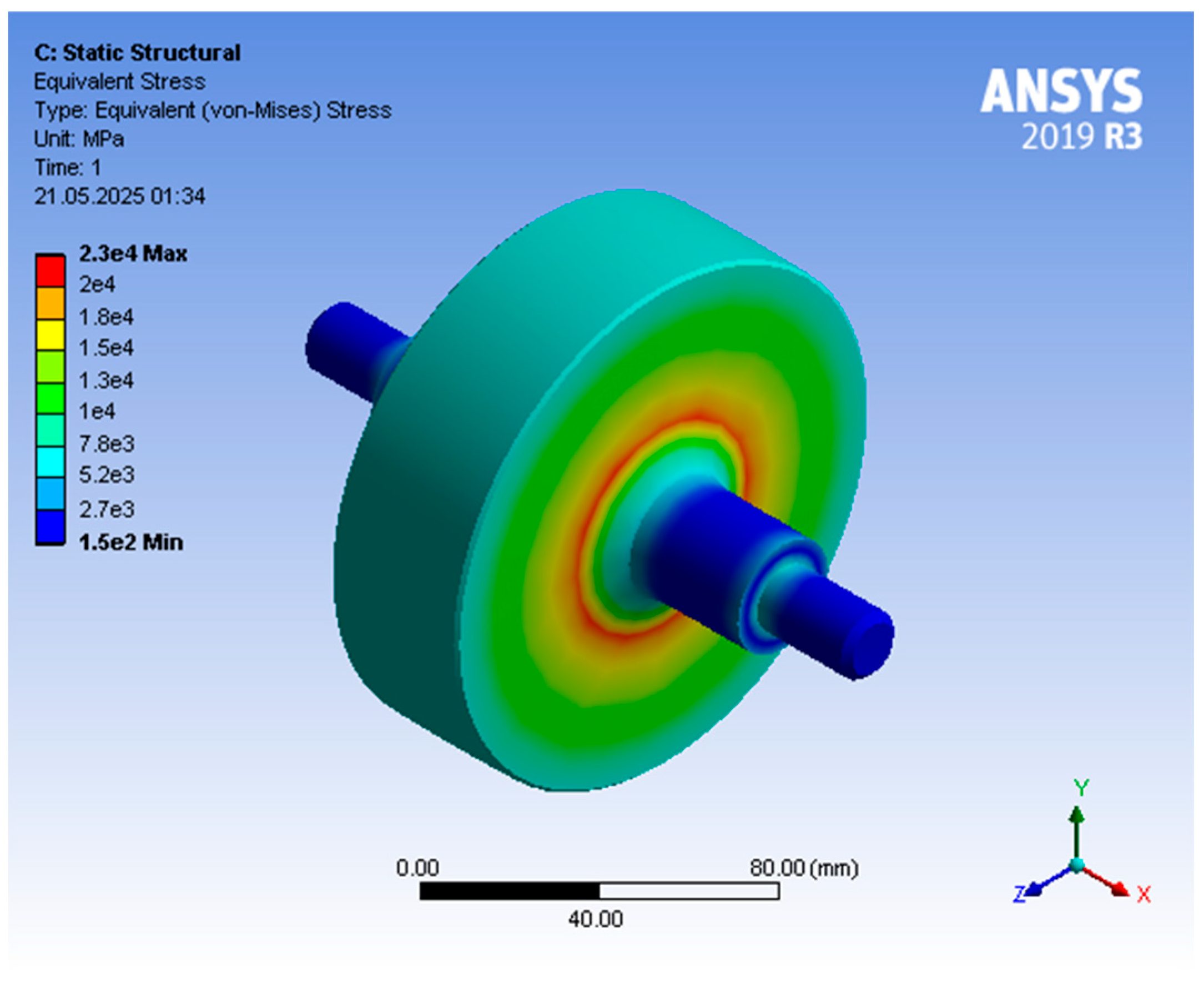
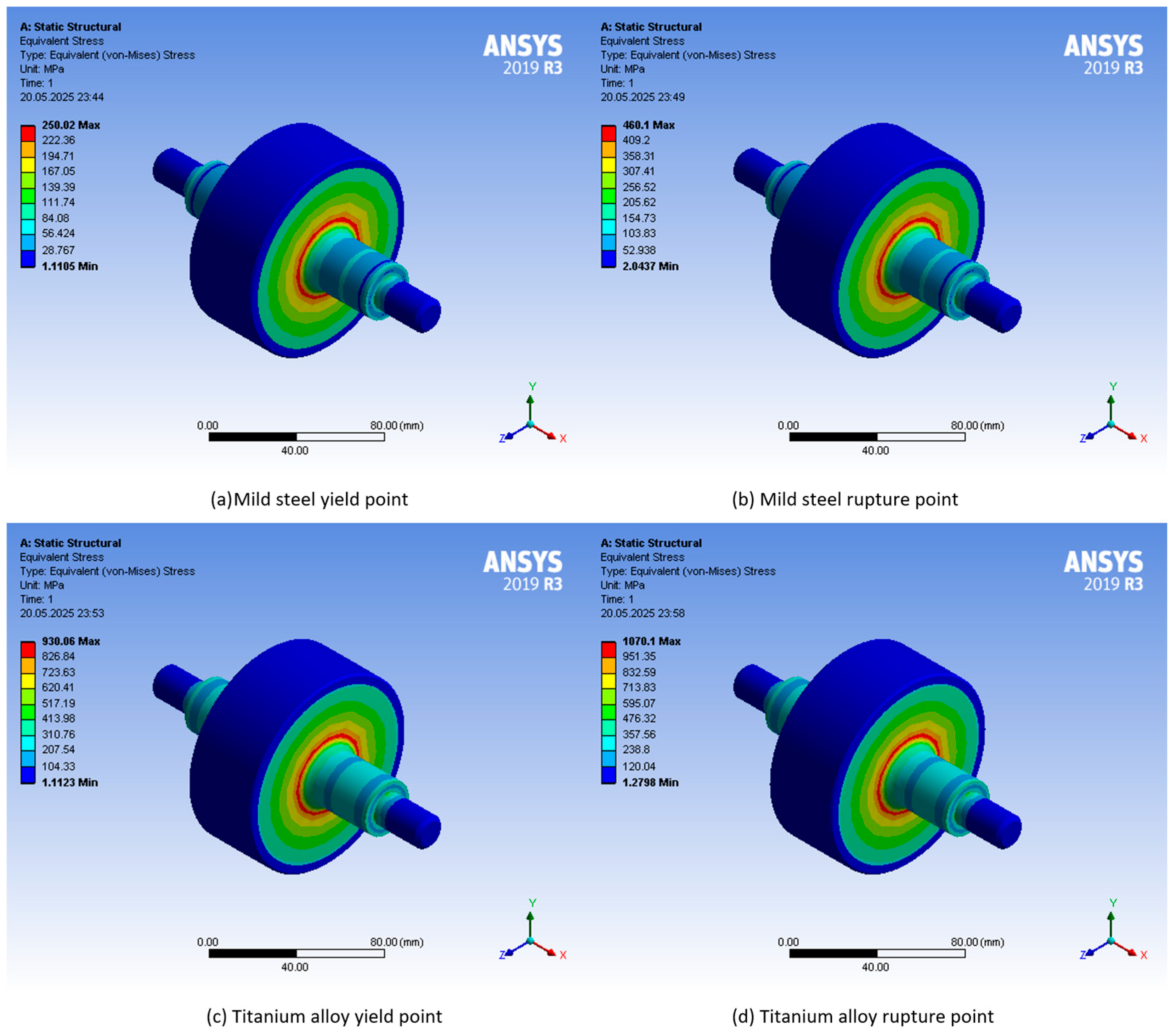
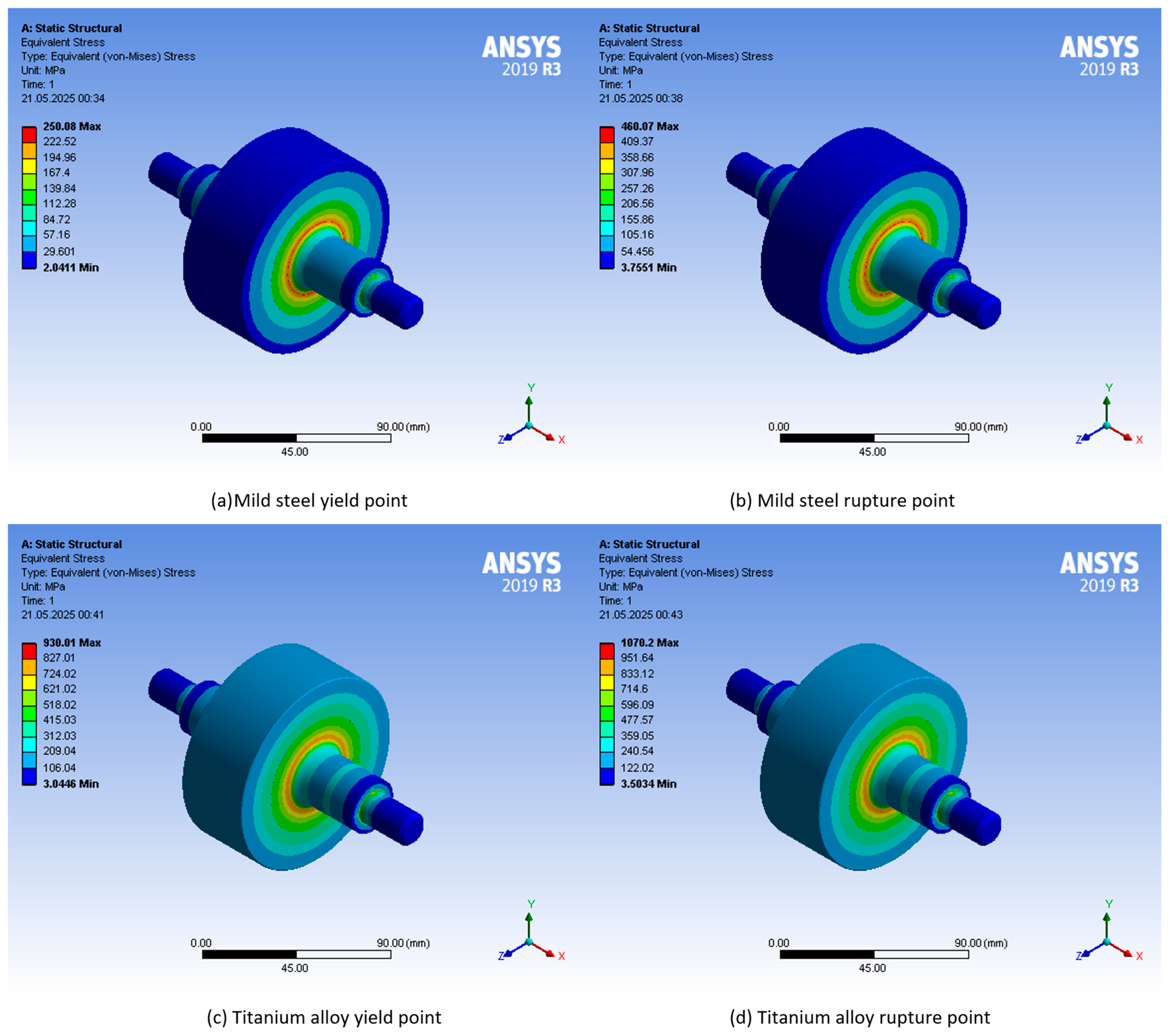
3.1. Solid Rotor Simulation Results

For mild steel and titanium alloy materials, the maximum speeds corresponding to the yield point and rupture point are simulated. For CFRP material, only the maximum speed for the rupture point value is simulated. Visuals of the simulation results are given in Figure 6 and Figure 7. As expected, the lowest speed belongs to mild steel with 50,700–68,740 RPM. Titanium alloy was able to reach the 125,700–137,000 RPM speed band due to its high strength. This value is more than twice that of mild steel. The highest speed can be reached with CFRP composite material due to having the highest strength. This shows why CFRP is preferred in aviation, space and military technologies. The data obtained with the solid rotor given in Table 5 constitute the base data for making comparisons with layered structures. With this comparison, the performance increase provided by the hybrid structure compared to the solid structure will be determined.

3.1.1. 3 mm Layered Hybrid Rotor Simulation Results

The performance obtained with the rotor structure with a 3 mm CFRP outer layer is higher than the solid rotor structure. The simulation results given in Table 6 clearly show that the RPM value that can be reached with the rotor with the 3 mm CFRP layer is 9.1% more than the solid rotor for mild steel. This ratio is 9.6% for titanium alloy.
In terms of weight, the mild-steel rotor with a 3 mm CFRP layer is 8% lighter than the solid steel rotor. Similarly, the titanium alloy rotor with a 3 mm CFRP layer is 5% lighter than the solid titanium alloy rotor. This means that the energy that can be stored with the hybrid rotor is 10–13% more (considering the correlation between the RPM value, rotor mass and the stored energy given in Equation (1)). Visuals of the simulation results are given in Figure 8.

3.1.2. 5 mm Layered Hybrid Rotor Simulation Results

The performance obtained with the rotor structure with a 5 mm CFRP outer layer is higher than the solid and 3 mm layered rotor structure. The simulation results given in Table 7 show that the RPM value that can be reached with the rotor with a 5 mm CFRP layer is 12.7% more than the solid rotor for mild steel. This ratio is 12.4% for titanium alloy. In terms of weight, the mild-steel rotor with a 5 mm CFRP layer is 11% lighter than the solid steel rotor. Similarly, the titanium alloy rotor with a 5 mm CFRP layer is 8% lighter than the solid titanium alloy rotor. This means that the energy that can be stored with the hybrid rotor is 12–14% higher. Visuals of the simulation results are given in Figure 9.

3.1.3. 10 mm Layered Hybrid Rotor Simulation Results

The performance obtained with the rotor structure with a 10 mm CFRP outer layer is higher than the solid and thinner multi-layered rotor structure. The simulation results given in Table 8 clearly show that the RPM value that can be reached with the rotor with the 10 mm CFRP layer is 20% more than the solid rotor for mild steel. This ratio is 15% for titanium alloy. In terms of weight, the mild-steel rotor with the 10 mm CFRP layer is 23% lighter than the solid steel rotor. Similarly, the titanium alloy rotor with the 10 mm CFRP layer is 18% lighter than the solid titanium alloy rotor. This means that the energy that can be stored with the hybrid rotor is 8–10% higher. At this point, when comparing the 10 mm CFRP layer with the 5 mm CFRP layer, the 10 mm layer shows lower performance. This is because the decrease in rotor mass has a greater effect than the increase in speed. These results show that there is an optimum point in terms of performance increase in the multi-layered structure. Visuals of the simulation results are given in Figure 10.

3.1.4. 20 mm Layered Hybrid Rotor Simulation Results

The performance obtained with the rotor structure with the 20 mm CFRP outer layer is higher than the solid and thinner multi-layered rotor structure. The simulation results given in Table 9 clearly show that the RPM value that can be reached with the rotor with the 20 mm CFRP layer is 45% higher than the solid rotor for mild steel. This ratio is 30% for titanium alloy. In terms of weight, the mild-steel rotor with a 20 mm CFRP layer is 41% lighter than the solid steel rotor. Similarly, the titanium alloy rotor with a 20 mm CFRP layer is 33% lighter than the solid titanium alloy rotor. This means that the energy that can be stored with the mild-steel CFRP hybrid rotor is 23% higher. This value is 14% for the titanium alloy–CFRP hybrid rotor. Similar to the 10 mm layered mild-steel-CFRP structure, a performance decrease is observed in the 20 mm layered rotor in the titanium alloy–CFRP structure. Visuals of the simulation results are given in Figure 11.
In the obtained results, it is observed that increasing the CFRP layer thickness above a certain value does not provide the expected increase in performance (in terms of stored energy). The reason for this is that the thick CFRP layer increases the maximum speed but lightens the mass. However, the fact that the composite structure lightens the total mass by up to 46% is an advantage in terms of mobility, aviation and space applications.

3.2. Analytical Calculations for the Solid Rotor

The ANSYS analysis results are validated by comparing them with the analytical solutions to confirm the accuracy of the simulation. In the calculations performed using Equation (3), the maximum rotor speeds are obtained and presented in Table 10. When the analytical calculations are compared with the analysis results, it is observed that the values coincide. This demonstrates the accuracy of the analysis results.

4. Discussion

When the obtained results are evaluated, the use of the multi-layer hybrid flywheel structure increases the maximum RPM value and reduces the total system weight. It is also observed that the energy storage capacity of these systems has increased to a certain extent. The studies are first carried out for the steel rotor structure. In order to prevent the rotor from breaking apart by exceeding the elasticity limit of the steel, carbon fiber layers of different thicknesses are added to the outside of the steel rotor, and simulations are performed accordingly. These simulations are repeated for 2 mm, 5 mm, 10 mm and 20 mm carbon fiber thicknesses. As the thickness of the carbon fiber layer increases, the maximum RPM value that the system can withstand also increases. As a result, the energy storage capacity of the system also increases. This situation is also valid for the titanium alloy rotor material. When Table 11 is examined carefully, it is clearly seen that the maximum RPM that the rotor can withstand increases with the tensile strength properties of the material and the thickness of the carbon fiber layer. The highest RPM value was obtained when the rotor was made entirely of carbon fiber. However, carbon composite material has a significantly higher manufacturing cost. The findings show that it is necessary to select the rotor structure and material according to the specific application and requirements of the FESS.
Another important point is that, when Equation (1) is taken into account, the decrease in rotor mass and the increase in speed without changing the geometric dimensions and the amount of stored energy result in a decrease in the moment of inertia of the rotor. Reducing the moment of inertia in mobile systems can be said to be a reduction in the counterforce applied during maneuvers (gyro effect).

Comparative Analysis of Systems

A comparison is given in Table 11 for different rotor materials. When evaluated in terms of yield and rupture strength, the manufacturing steel has the lowest values. However, it also has the highest weight. As stated in Equation (1), the energy stored in FESS increases linearly with the rotor weight. However, it increases proportionally with the square of the rotor speed. Therefore, the rotor weight and rotor speed should be evaluated together in the calculation of the stored energy. Although the titanium alloy weighs 58.85% of the manufacturing steel, its yield and rupture strength values are significantly higher. The carbon composite material weighs 23% of the manufacturing steel and 39% of the titanium alloy. However, the carbon composite material has the highest strength among these materials due to its physical structure. Despite its low weight, its ability to reach very high speeds allows it to store the highest energy among all other materials. Despite its high cost, its high energy density makes it highly strategic in mobility applications.
In hybrid structures, the total system weight varies depending on the percentage of materials used, as shown in Table 11. As the thickness of the carbon fiber increases, the total weight of the rotor decreases. However, RPM, manufacturing costs, and manufacturing difficulties also increase. The situations are similar for steel–carbon fiber and titanium alloy–carbon fiber hybrid structures. Table 12 shows the maximum RPM and peripheral speed (km/h) values that can be achieved by considering the yield and rupture values according to different rotor materials. Carbon fiber is the rotor material that can reach the highest RPM, with a value of 950,000. This is equal to a peripheral speed of 18,000 km/h. The rotor with the lowest RPM is manufactured with manufacturing steel, and its peripheral speed is equivalent to 1300 km/h. In the hybrid structure, the peripheral speed value increases as the carbon fiber thickness increases.
Table 13 shows the maximum kinetic energy values that can be stored according to rotor materials in “Watt-hour (Wh)”. As given in Equation (1), the kinetic energy stored on the rotating mass is proportional to the square of the speed, while it changes linearly with the weight. The energy stored for the equivalent rotor geometry depending on the rupture point stress for manufacturing steel is 26 Wh. The stored energy value of titanium alloy is 63 Wh, more than twice that of manufacturing steel.
Since the RPM corresponding to the rupture stress for the carbon composite rotor is quite high, the stored energy increases very significantly. However, in order to reach these revolutions with the carbon composite rotor, not only the material strength but also the other parts of the storage system must be able to withstand these speeds. For example, when dynamic and static loads are considered, it is not possible to find a ready-made bearing that can withstand these speeds. The bearings to be used in a system reaching these speeds must be specially developed.
When the stored energy is theoretically examined, there is a difference of approximately 45-times between the carbon composite and steel and 19-times with titanium alloy. In terms of speed, the carbon composite rotor rotates 14-times faster than steel and 7-times faster than titanium alloy. The energy stored in the hybrid structure varies between 29 Wh and 32 Wh depending on the thickness of the steel–carbon composite rotor and between 67 and 68 Wh depending on the thickness of the titanium alloy–carbon composite.
Table 14 shows values, such as material cost, manufacturing cost, energy storage capacity, energy density, total system weight and maximum speed, for different rotor materials. The manufacturing costs and material costs of different rotors are rated on a Likert scale between 1 and 5. In this scaling system, 1 indicates the lowest cost and 5 indicates the highest cost. Manufacturing steel is determined as 1, titanium alloy as 2, manufacturing steel–carbon composite hybrid structure as 3, titanium alloy–carbon composite hybrid structure as 4 and all carbon fiber as 5 in terms of material and ease of processing.
The comparison table is prepared by looking at the maximum RPM equivalent to the rupture point stresses. A ranking is made depending on the Likert scale. The rotor made of manufacturing steel is the heaviest rotor, as well as the material with the lowest RPM, manufacturing cost, material cost, and energy storage capacity. Carbon fiber is seen to be the opposite. At the same time, the rotor with the highest carbon thickness is seen to be the lightest rotor in the hybrid structure. Although multi-rim rotors exhibit up to 200% higher energy density compared to steel and titanium rotors, their reliability may be compromised due to their complex structure. The metal core and the carbon fiber layers—either bonded or wound around it—may gradually separate over time as a result of aging, leading to further degradation. Hybrid rotor systems are anticipated to achieve higher rotational speeds than solid rotors. This advancement necessitates the fabrication of multi-layer systems with more precise and advanced manufacturing technologies.

5. Conclusions

Composite flywheels represent a challenging field of study due to factors, such as the technical properties of materials, design criteria, various geometric shapes, and manufacturing methods. As an innovation in this study, a system was designed with a metal core and a composite outer layer. Analyses were conducted for both steel and titanium as the metal core. Additionally, the effects of carbon composite layer thicknesses on the system’s energy and speed values were observed.
When the obtained data are evaluated, it is seen that manufacturing steel alone is sufficient for applications requiring a peripheral speed of up to 250 m/s. However, to reach a value of 500 m/s, a titanium alloy or a titanium–carbon composite multi-layer structure would be preferred. For peripheral speeds ranging from 500 m/s to 2500 m/s, a fully carbon composite rotor structure is required. According to the results, the hybrid use of titanium and carbon composite materials does not significantly contribute to an energy enhancement, as the increase is only around 15%. Taking the risks associated with a hybrid structure for a mere 15% energy increase is not considered worthwhile. However, if the goal is to enhance energy density, a 65% increase is observed in the hybrid structure. Furthermore, in steel rotor structures, the energy density increase can exceed 100%.
In conclusion, carbon composite represents the highest level of performance in terms of lightness, strength, and energy density. However, high manufacturing and material costs make it challenging to choose for low-performance and cost-sensitive applications. In sectors where cost is a secondary concern, such as aerospace, aviation, and military technologies, carbon fiber rotor structures are frequently preferred. Due to their mechanical strength properties, steel rotors are disadvantaged compared to titanium and carbon composite materials in terms of performance and durability. However, owing to their ease of manufacturing and reasonable material costs, steel rotors can be used in grid-based energy storage solutions and relatively low-speed applications. The multi-layer hybrid rotor structure examined in this study and presented as an original contribution is found to enhance energy density due to the resulting weight reduction.

Author Contributions

Methodology, C.Y.; Formal analysis, C.Y.; Investigation, K.E.; Writing—original draft, K.E.; Writing—review & editing, K.E.; Visualization, C.Y.; Supervision, K.E. All authors have read and agreed to the published version of the manuscript.

Funding

This research received no external funding.

Institutional Review Board Statement

Not applicable.

Informed Consent Statement

Not applicable.

Data Availability Statement

The original contributions presented in this study are included in the article. Further inquiries can be directed to the corresponding author.

Conflicts of Interest

The authors declare no conflict of interest.

References

  1. Choudhury, S. Flywheel energy storage systems: A critical review on technologies, applications, and future prospects. Int. Trans. Electr. Energy Syst. 2021, 31, e13024. [Google Scholar] [CrossRef]
  2. Amiryar, M.E.; Pullen, K.R. A review of flywheel energy storage system technologies and their applications. Appl. Sci. 2017, 7, 286. [Google Scholar] [CrossRef]
  3. Hedlund, M.; Lundin, J.; De Santiago, J.; Abrahamsson, J.; Bernhoff, H. Flywheel energy storage for automotive applications. Energies 2015, 8, 10636–10663. [Google Scholar] [CrossRef]
  4. Erhan, K. Investigation of Flywheel and Ultracapacitor Technologies Used in Electric and Hybrid Electric Vehicles and Prototype Production of Flywheel Energy Storage Unit; Kocaeli University: İzmit, Turkey, 2018. [Google Scholar]
  5. Ayaz, M.; Icer, Y.; Karabinaoglu, M.S.; Erhan, K. Energy management algorithm development for smart car parks including charging stations, storage, and renewable energy sources. Comput. Electr. Eng. 2024, 119, 109478. [Google Scholar] [CrossRef]
  6. Akram, U.; Nadarajah, M.; Shah, R.; Milano, F. A review on rapid responsive energy storage technologies for frequency regulation in modern power systems. Renew. Sustain. Energy Rev. 2020, 120, 109626. [Google Scholar] [CrossRef]
  7. Sebastián, R.; Alzola, R.P. Flywheel energy storage systems: Review and simulation for an isolated wind power system. Renew. Sustain. Energy Rev. 2012, 16, 6803–6813. [Google Scholar] [CrossRef]
  8. Karrari, S.; Noe, M.; Geisbuesch, J. High-speed flywheel energy storage system (FESS) for voltage and frequency support in low voltage distribution networks. In Proceedings of the 2018 IEEE 3rd International Conference on Intelligent Energy and Power Systems (IEPS), Kharkiv, Ukraine, 10–14 September 2018; pp. 176–182. [Google Scholar]
  9. Available online: https://interestingengineering.com/energy/china-world-largest-flywheel-energy-storage (accessed on 20 December 2024).
  10. Erhan, K.; Özdemir, E. Prototype production and comparative analysis of high-speed flywheel energy storage systems during regenerative braking in hybrid and electric vehicles. J. Energy Storage 2021, 43, 103237. [Google Scholar] [CrossRef]
  11. Li, X.; Palazzolo, A. A review of flywheel energy storage systems: State of the art and opportunities. J. Energy Storage 2022, 46, 103576. [Google Scholar] [CrossRef]
  12. Kim, S.J.; Hayat, K.; Nasir, S.U.; Ha, S.K. Design and fabrication of hybrid composite hubs for a multi-rim flywheel energy storage system. Compos. Struct. 2014, 107, 19–29. [Google Scholar] [CrossRef]
  13. Rastegarzadeh, S.; Mahzoon, M.; Mohammadi, H. A novel modular designing for multi-ring flywheel rotor to optimize energy consumption in light metro trains. Energy 2020, 206, 118092. [Google Scholar] [CrossRef]
  14. Li, X.; Mittelstedt, C.; Binder, A. A review of critical issues in the design of lightweight flywheel rotors with composite materials. E I Elektrotechnik Informationstechnik 2022, 139, 204–221. [Google Scholar] [CrossRef]
  15. Ha, S.K.; Kim, D.J.; Sung, T.H. Optimum design of multi-ring composite flywheel rotor using a modified generalized plane strain assumption. Int. J. Mech. Sci. 2001, 43, 993–1007. [Google Scholar]
  16. Wen, S.; Jiang, S. Optimum design of hybrid composite multi-ring flywheel rotor based on displacement method. Compos. Sci. Technol. 2012, 72, 982–988. [Google Scholar] [CrossRef]
  17. Hu, D.; Dai, X.; Li, W.; Zhu, Y.; Zhang, X.; Chen, H.; Zhang, Z. A review of flywheel energy storage rotor materials and structures. J. Energy Storage 2023, 74, 109076. [Google Scholar]
  18. Chen, H.; Cong, T.N.; Yang, W.; Tan, C.; Li, Y.; Ding, Y. Progress in electrical energy storage system: A critical review. Prog. Nat. Sci. 2009, 19, 291–312. [Google Scholar] [CrossRef]
  19. Arslan, M.A. Flywheel geometry design for improved energy storage using finite element analysis. Mater. Des. 2008, 29, 514–518. [Google Scholar] [CrossRef]
  20. Molina, M.G. Dynamic modelling and control design of advanced energy storage for power system applications. Dyn. Model. 2010, 300, 49–92. [Google Scholar]
  21. Brockbank, C.; Greenwood, C. Fuel economy benefits of a flywheel & CVT based mechanical hybrid for city bus and commercial vehicle applications. SAE Int. J. Commer. Veh. 2009, 2, 115–122. [Google Scholar]
  22. Wang, P.; Gu, T.; Sun, B.; Liu, R.; Zhang, T.; Yang, J. Design and Performance Analysis of Super Highspeed Flywheel Rotor for Electric Vehicle. World Electr. Veh. J. 2022, 13, 147. [Google Scholar] [CrossRef]
  23. Cross, D.; Brockbank, C. Mechanical Hybrid System Comprising a Flywheel and CVT for Motorsport and Mainstream Automotive Applications; SAE Technical Paper; SAE: Warrendale, PA, USA, 2009. [Google Scholar] [CrossRef]
  24. Akhil, A.A.; Huff, G.; Currier, A.B.; Kaun, B.C.; Rastler, D.M.; Chen, S.B.; Gauntlett, W.D. DOE/EPRI 2013 Electricity Storage Handbook in Collaboration with NRECA; Sandia National Laboratories: Albuquerque, NM, USA, 2013; Volume 1, p. 340. [Google Scholar]
  25. Ragheb, M.; Tung, M.T. Kinetic Energy Flywheel Energy Storage; University of Illinois at Urbana Champaign: Champaign, IL, USA, 2013. [Google Scholar]
  26. Kamf, T. High Speed Flywheel Design: Using Advanced Composite Materials. Master’s Thesis, Uppsala University, Uppsala, Sweden, 2012. [Google Scholar]
  27. Genta, G. Kinetic Energy Storage: Theory and Practice of Advanced Flywheel Systems; Butterworth-Heinemann: Oxford, UK, 2014. [Google Scholar]
  28. Conteh, M.A.; Nsofor, E.C. Composite flywheel material design for high-speed energy storage. J. Appl. Res. Technol. 2016, 14, 184–190. [Google Scholar] [CrossRef]
  29. Olabi, A.G.; Wilberforce, T.; Abdelkareem, M.A.; Ramadan, M. Critical review of flywheel energy storage system. Energies 2021, 14, 2159. [Google Scholar] [CrossRef]
  30. Kale, V.; Thomas, M.; Secanell, M. On determining the optimal shape, speed, and size of metal flywheel rotors with maximum kinetic energy. Struct. Multidiscip. Optim. 2021, 64, 1481–1499. [Google Scholar] [CrossRef]
  31. Kale, V.; Secanell, M. A comparative study between optimal metal and composite rotors for flywheel energy storage systems. Energy Rep. 2018, 4, 576–585. [Google Scholar] [CrossRef]
  32. Pihulkar, A.A.; Sarje, S.H. Design of Composite Material Flywheel. IJSTE Int. J. Sci. Technol. Eng. 2017, 3, 191–197. [Google Scholar]
  33. Ji, P.; Nie, W.-W.; Liu, J.-L. Research on Magnetic Coupling Flywheel Energy Storage Device for Vehicles. Appl. Sci. 2023, 13, 6036. [Google Scholar] [CrossRef]
  34. Floris, A.; Porru, M.; Damiano, A.; Serpi, A. Energy Management and Control System Design of an Integrated Flywheel Energy Storage System for Residential Users. Appl. Sci. 2021, 11, 4615. [Google Scholar] [CrossRef]
  35. Skinner, M.; Mertiny, P. Effects of Viscoelasticity on the Stress Evolution over the Lifetime of Filament-Wound Composite Flywheel Rotors for Energy Storage. Appl. Sci. 2021, 11, 9544. [Google Scholar] [CrossRef]
  36. Mittelstedt, M.; Hansen, C.; Mertiny, P. Design and Multi-Objective Optimization of Fiber-Reinforced Polymer Composite Flywheel Rotors. Appl. Sci. 2018, 8, 1256. [Google Scholar] [CrossRef]
  37. Anand, A.; Roy, H. Static and dynamic analysis of lathe spindle using ANSYS. Int. J. Appl. Eng. Res. 2018, 13, 6994–7000. [Google Scholar]
  38. Afane, N.E.B.; Zahaf, S.; Dahmane, M.; Belaziz, A.; Noureddine, R. Modal and harmonic analysis of the rotor system involving four different materials by finite element code: Ansys workbench. Mater. Phys. Mechanics 2023, 51, 63–98. [Google Scholar]
  39. Liu, D.P.; Zhang, H.; Tao, Z. Analysis of Static and Dynamic Characteristics of Milling Motorized Spindle Based on ANSYS. Adv. Mater. Res. 2011, 154, 179–183. [Google Scholar] [CrossRef]
  40. Jalali, M.H.; Ghayour, M.; Ziaei-Rad, S.; Shahriari, B. Dynamic analysis of a high-speed rotor-bearing system. Measurement 2014, 53, 1–9. [Google Scholar] [CrossRef]
Figure 1. Flywheel energy storage system structure [20].
Applsci 15 05759 g001
Figure 2. Bus application of FESS [23].
Applsci 15 05759 g002
Figure 3. Shape factors of different rotor geometries for FESS [29].
Applsci 15 05759 g003
Figure 4. Technical drawing and dimensions of Ø 100 mm FESS rotor.
Applsci 15 05759 g004
Figure 5. Rotor designs utilized in simulations: one-piece, 3 mm, 5 mm, 10 mm, and 20 mm layered structure.
Applsci 15 05759 g005
Figure 6. Simulation visuals: stress and rupture values for steel and titanium alloys.
Applsci 15 05759 g006
Figure 7. Simulation visuals: stress and rupture values for carbon fiber-reinforced polymer (CFRP).
Applsci 15 05759 g007
Figure 8. Simulation visuals: stress and rupture values for steel and titanium alloys with 3 mm CFRP layer.
Applsci 15 05759 g008
Figure 9. Simulation visuals: stress and rupture values for steel and titanium alloys with 5 mm CFRP layer.
Applsci 15 05759 g009
Figure 10. Simulation visuals: stress and rupture values for steel and titanium alloys with 10 mm CFRP layer.
Applsci 15 05759 g010
Figure 11. Simulation visuals: stress and rupture values for steel and titanium alloys with 20 mm CFRP layer.
Applsci 15 05759 g011
Table 1. Material specifications for rotor of FESS [17,27,28].
MaterialDensity (kg/m3), ρTensile Strength (MPa), σEnergy Density (Wh/kg)Cost (USD/lb)
Grey Cast Iron (GCI 25)7340220n/an/a
Steel (AICI 4340)78001800641
Aluminum Alloy (AlMnMg)2800600613
Titanium (TiAl6Zr5)45001200759
Carbon fiber (S2)1920147021324.6
Carbon fiber (M30S)15532760493n/a
Carbon fiber composite (T1000G)16643620604101.8
Table 2. Structural properties of mild steel.
Density7850 kg/m3
Young’s Modulus2 × 108 Pa
Poisson’s ratio0.3000
Bulk modulus1.6667 × 1011 Pa
Slip modulus7.6923 × 1011 Pa
Thermal coefficient of expansion1.2 × 10−5 1/°C
Yield stress2.5 × 108 Pa
Ultimate tensile strength4.6 × 108 Pa
Tensile stress2.05 × 108 Pa
Thermal conductivity60.500 W/m·°C
Specific heat434.00 J/kg·°C
Specific strength26 kPa/(kg/m3)
Table 3. Structural properties of titanium alloy.
Density4620 kg/m3
Young’s Modulus9.6 × 1010 Pa
Poisson’s ratio0.36000
Bulk modulus1.1429 × 1011 Pa
Slip modulus3.5294 × 1010 Pa
Thermal coefficient of expansion9.4 × 10−6 1/°C
Yield stress9.3 × 108 Pa
Ultimate tensile strength1.07 × 109 Pa
Tensile stress9.0 × 108 Pa
Thermal conductivity21.900 W/m·°C
Specific heat522.00 J/kg·°C
Specific strength200 kPa/(kg/m3)
Table 4. Structural properties of carbon composite material.
Density1800 kg/m3
Young’s Modulus X-axis2.3 × 1011 Pa
Young’s Modulus Y-axis2.3 × 1010 Pa
Young’s Modulus Z-axis2.3 × 1010 Pa
Poisson’s ratio XY0.20000
Poisson’s ratio YZ0.40000
Poisson’s ratio XZ0.20000
Slip modulus XY9 × 109 Pa
Slip modulus YZ8.2143 × 109 Pa
Slip modulus XZ9 × 109 Pa
Specific strength12.8 MPa/(kg/m3)
Table 5. Rupture and yield stress values of 100 mm rotor.
Amb. Temp.: 22 °C
Ø 100 mm Rotor
Mild SteelMild SteelTitanium AlloyTitanium AlloyCarbon Fiber-Reinforced Polymer
Yield PointRupture PointYield PointRupture PointRupture Point
Speed (RPM)50,70068,740125,700137,000952,520
Weight (kg)2.92.91.71.70.67
Minimum (MPa)0.751.380.871.03145.7
Maximum (MPa)250460901107123,000
Table 6. Rupture and yield stress values of 100 mm rotor with 3 mm CFRP layer.
Amb. Temp.: 22 °C
Ø 100 mm Rotor with 3 mm CFRP Layer
Mild Steel
+
3 mm CFRP
Mild Steel
+
3 mm CFRP
Titanium Alloy
+
3 mm CFRP
Titanium Alloy
+
3 mm CFRP
Yield PointRupture PointYield PointRupture Point
Speed (RPM)55,35075,080137,850147,900
Weight (kg)2.64 + 0.0652.64 + 0.0651.55 + 0.0651.55 + 0.065
Minimum (MPa)0.991.820.951.1
Maximum (MPa)2504609301071
Table 7. Rupture and yield stress values of 100 mm rotor with 5 mm CFRP layer.
Amb. Temp.: 22 °C
Ø 100 mm Rotor with 5 mm CFRP Layer
Mild Steel
+
5 mm CFRP
Mild Steel
+
5 mm CFRP
Titanium Alloy
+
5 mm CFRP
Titanium Alloy
+
5 mm CFRP
Yield PointRupture PointYield PointRupture Point
Speed (RPM)57,15077,520141,260151,500
Weight (kg) 2.46 + 0.112.46 + 0.111.45 + 0.111.45 + 0.11
Minimum (MPa)1.12.11.11.3
Maximum (MPa)2504609301070
Table 8. Rupture and yield stress values of 100 mm rotor with 10 mm CFRP layer.
Amb. Temp.: 22 °C
Ø 100 mm Rotor with 10 mm CFRP Layer
Mild Steel
+
10 mm CFRP
Mild Steel
+
10 mm CFRP
Titanium Alloy
+
10 mm CFRP
Titanium Alloy
+
10 mm CFRP
Yield PointRupture PointYield PointRupture Point
Speed (RPM)60,60082,140144,850155,350
Weight (kg)2.04 + 0.22.04 + 0.21.2 + 0.21.2 + 0.2
Minimum (MPa)0.961.771.371.58
Maximum (MPa)2504609301070
Table 9. Rupture and yield stress values of 100 mm rotor with 20 mm CFRP layer.
Amb. Temp.: 22 °C
Ø 100 mm Rotor with 20 mm CFRP Layer
Mild Steel
+
20 mm CFRP
Mild Steel
+
20 mm CFRP
Titanium Alloy
+
20 mm CFRP
Titanium Alloy
+
20 mm CFRP
Yield PointRupture PointYield PointRupture Point
Speed (RPM)73,50096,650163,860175,800
Weight (kg)1.33 + 0.361.33 + 0.360.8 + 0.360.8 + 0.36
Minimum (MPa)2.13.831.5
Maximum (MPa)2504609301071
Table 10. Comparison of analytical calculation results and simulation results for a 100 mm solid rotor, considering the yield stress values.
Amb. Temp.: 22 °C
Ø 100 mm Rotor
Mild SteelTitanium AlloyCarbon Fiber-Reinforced Polymer
Yield PointYield PointRupture Point
Speed (RPM) (Analytical)53,047132,2201,047,211
Speed (RPM) (ANSYS)50,700125,700952,520
Weight (kg)2.91.70.67
Maximum (MPa)25090123,000
Table 11. Maximum RPM and total rotor weight values of different rotor materials.
Rotor MaterialYield Stress
(RPM)
Rupture Stress
(RPM)
Total Rotor Weight
(kg)
Mild steel50,70068,7402.9203
Titanium alloy125,700137,0001.7187
CFRP (230 GPA)-952,5000.6696
Hybrid structure
Mild steel—3 mm CFRP55,35075,0802.7023 (M: 97.6% C: 2.4%)
Mild steel—5 mm CFRP57,15077,5202.5634 (M: 95.8% C: 4.2%)
Mild steel—10 mm CFRP60,60082,1402.2413 (M: 91% C: 9%)
Mild steel—20 mm CFRP73,50099,6501.7115 (M: 77.7% C: 22.3%)
Titanium alloy—3 mm CFRP137,580147,9001.6173 (T: 96% C: 4%)
Titanium alloy—5 mm CFRP141,260151,5001.5526 (T: 93.1% C: 6.9%)
Titanium alloy—10 mm CFRP144,850155,3501.4025 (T: 85.5% C: 14.5%)
Titanium alloy—20 mm CFRP163,860175,8001.1558 (T: 68.8% C: 31.2%)
C: Mass ratio for CFRP. M: Mass ratio for mild steel. T: Mass ratio for titanium alloy.
Table 12. Maximum RPM and peripheral speed values of different rotor materials.
Rotor MaterialYield Stress
(RPM)
Yield Stress
(km/h)
Rupture Stress
(RPM)
Rupture Stress
(km/h)
Mild steel50,700955.6768,7401295.72
Titanium alloy125,7002369.4137,0002582.4
CFRP (230 GPA)--952,50017,954.2
Hybrid structure
Mild steel—3 mm CFRP55,3501043.3275,0801415.22
Mild steel—5 mm CFRP57,1501077.2577,5201461.22
Mild steel—10 mm CFRP60,6001142.2882,1401548.3
Mild steel—20 mm CFRP73,5001385.4499,6501878.36
Titanium alloy—3 mm CFRP137,5802593.32147,9002787.85
Titanium alloy—5 mm CFRP141,2602662.7151,5002855.7
Titanium alloy—10 mm CFRP144,8502730.36155,3502928.28
Titanium alloy—20 mm CFRP163,8603088.7175,8003313.75
Table 13. Stored energy according to the flywheel structure.
Rotor MaterialYield Stress
(RPM)
Stored Energy
(Wh)
Rupture Stress
(RPM)
Stored Energy
(Wh)
Mild steel50,70014.2968,74026.27
Titanium alloy125,70051.7137,00061.42
CFRP (230 GPA)--952,5001156.63
Hybrid structure
Mild steel—3 mm CFRP55,35015.7675,08029
Mild steel—5 mm CFRP57,15015.9477,52029.3
Mild steel—10 mm CFRP60,60015.6782,14028.8
Mild steel—20 mm CFRP73,50017.699,65032.32
Titanium alloy—3 mm CFRP137,58058.28147,90067.35
Titanium alloy—5 mm CFRP141,26059151,50067.85
Titanium alloy—10 mm CFRP144,85056155,35064.44
Titanium alloy—20 mm CFRP163,86059.1175,80068
Table 14. Comparison of systems according to different rotor materials.
Rotor MaterialMaximum
RPM
Production CostMaterial CostStored Energy
(Wh)
Total Rotor Weight (kg)Energy Density (Wh/kg)
Mild steel68,7401126.272.929
Titanium alloy137,0002261.421.7235.7
Mild steel—20 mm CFRP99,6503332.321.7118.9
Titanium alloy—20 mm CFRP175,80044681.1658.8
CFRP (23 GPA)952,500551156.630.671727
Disclaimer/Publisher’s Note: The statements, opinions and data contained in all publications are solely those of the individual author(s) and contributor(s) and not of MDPI and/or the editor(s). MDPI and/or the editor(s) disclaim responsibility for any injury to people or property resulting from any ideas, methods, instructions or products referred to in the content.

