
Experimental Behavior and FE Modeling of Buckling Restrained Braced Frame with Slip-Critical Connection

Abstract
1. Introduction
2. Materials and Methods
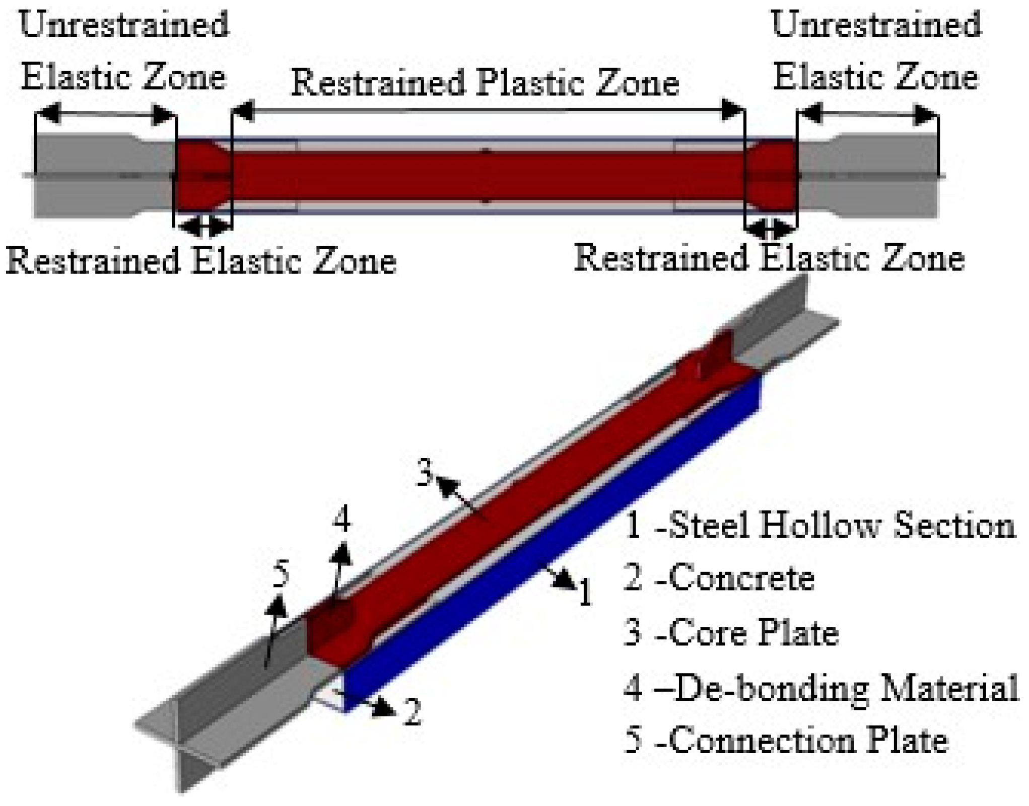
2.1. BRB Test Specimens
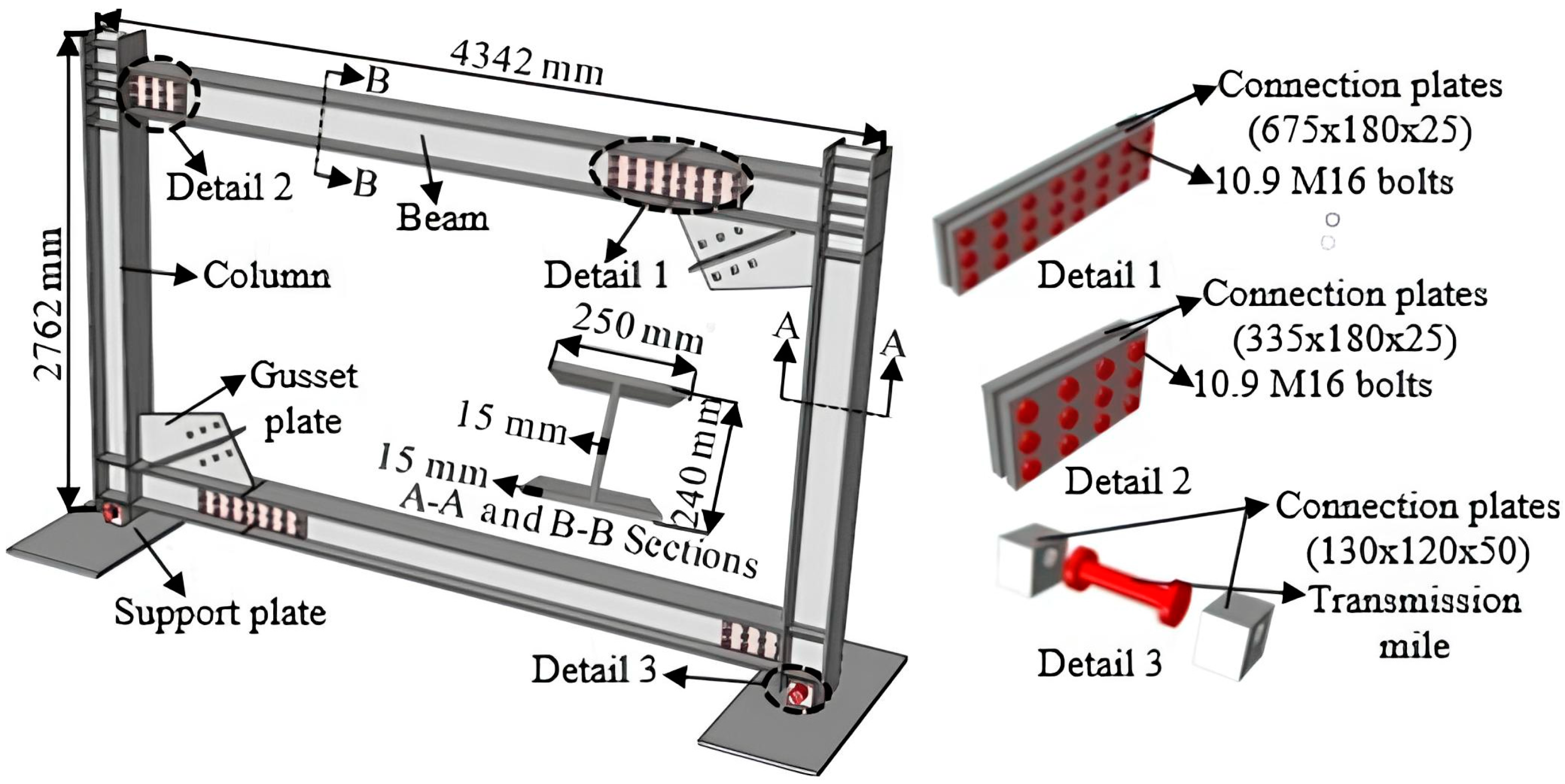
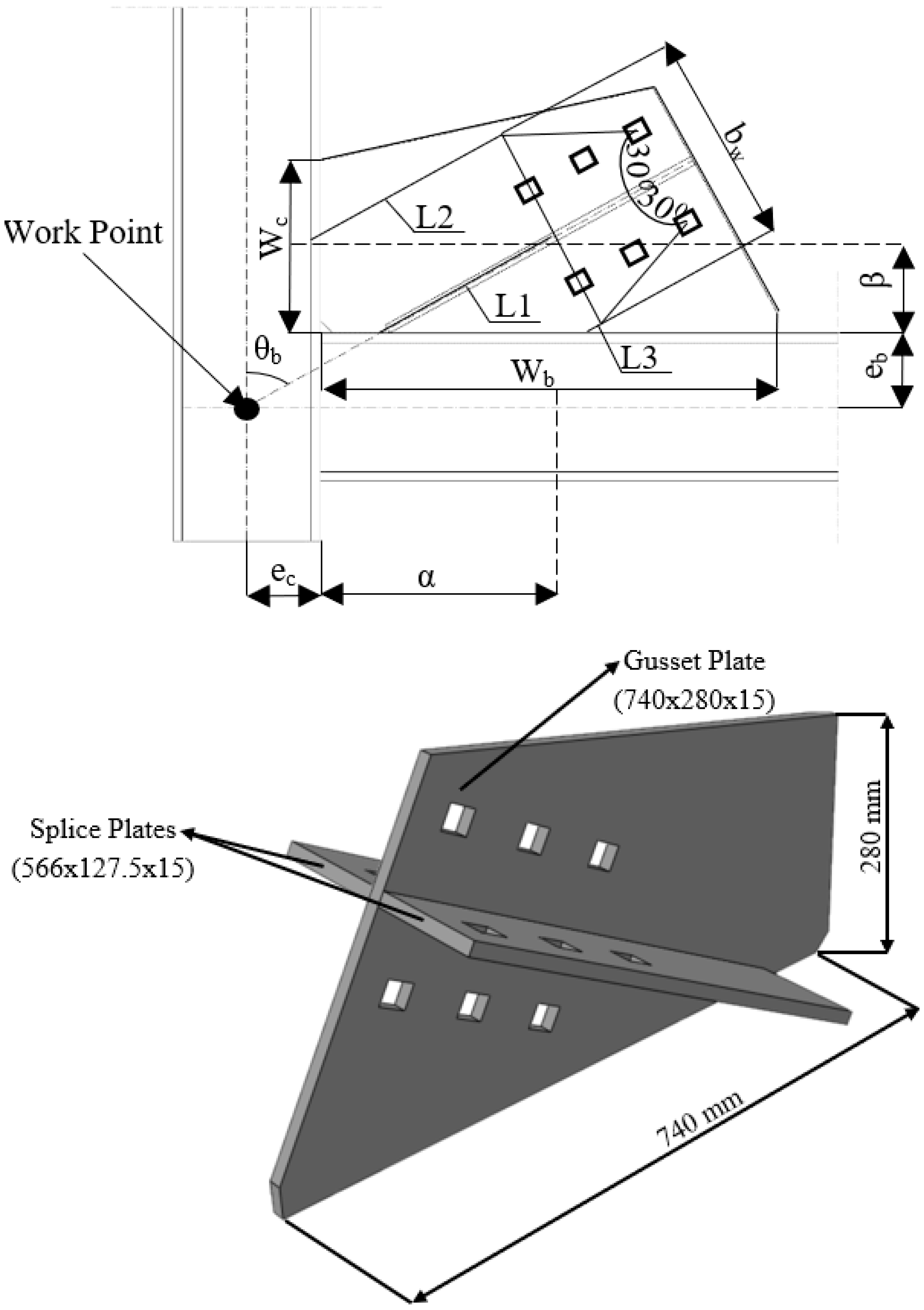
2.2. Steel Frame
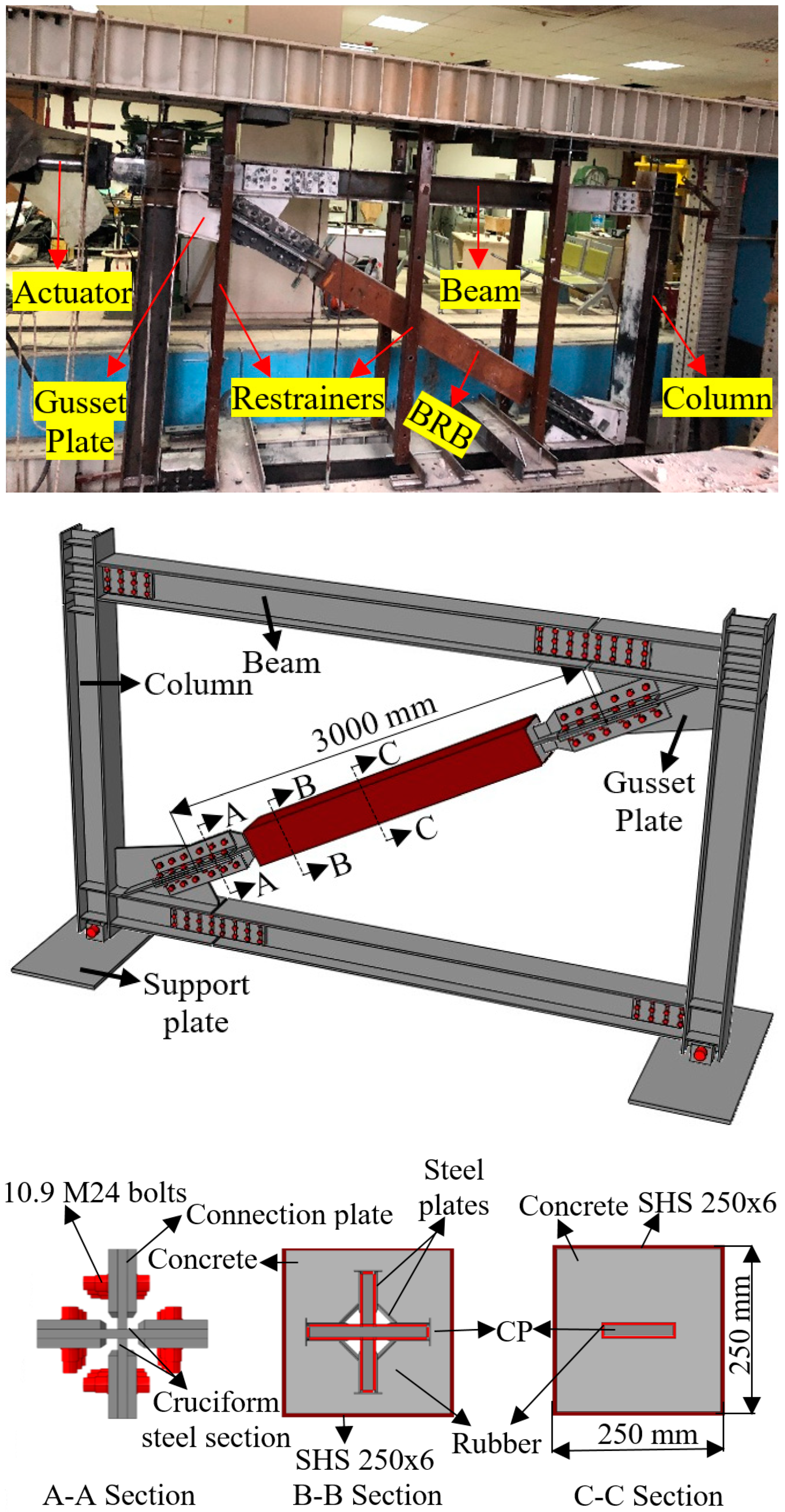
2.3. The BRBF
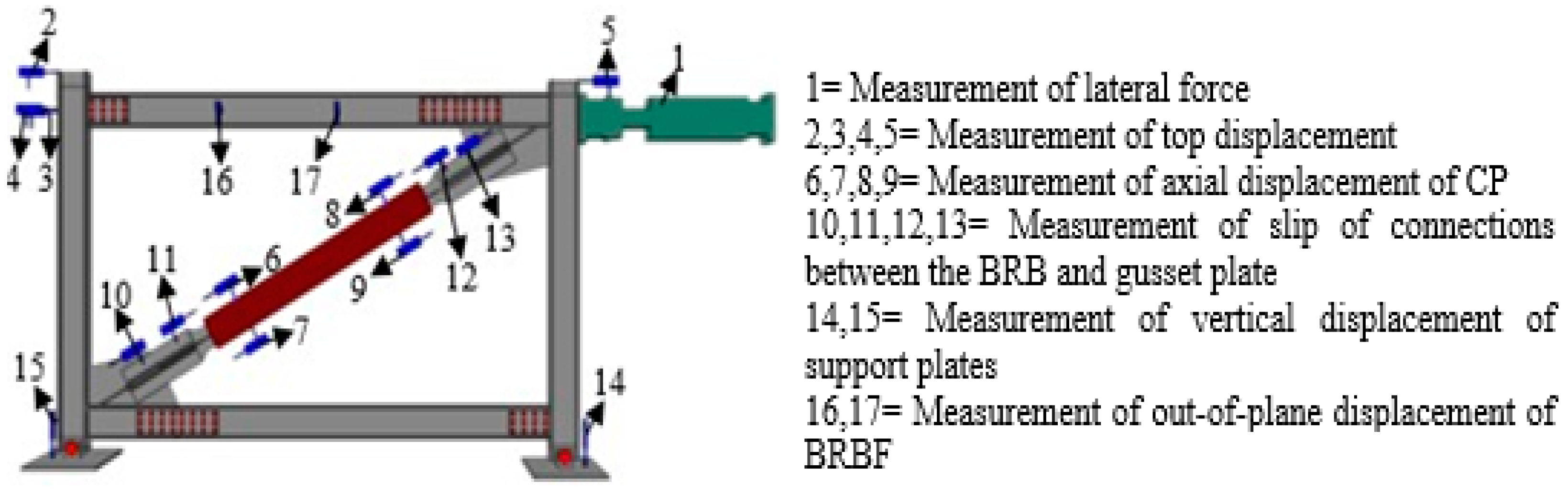
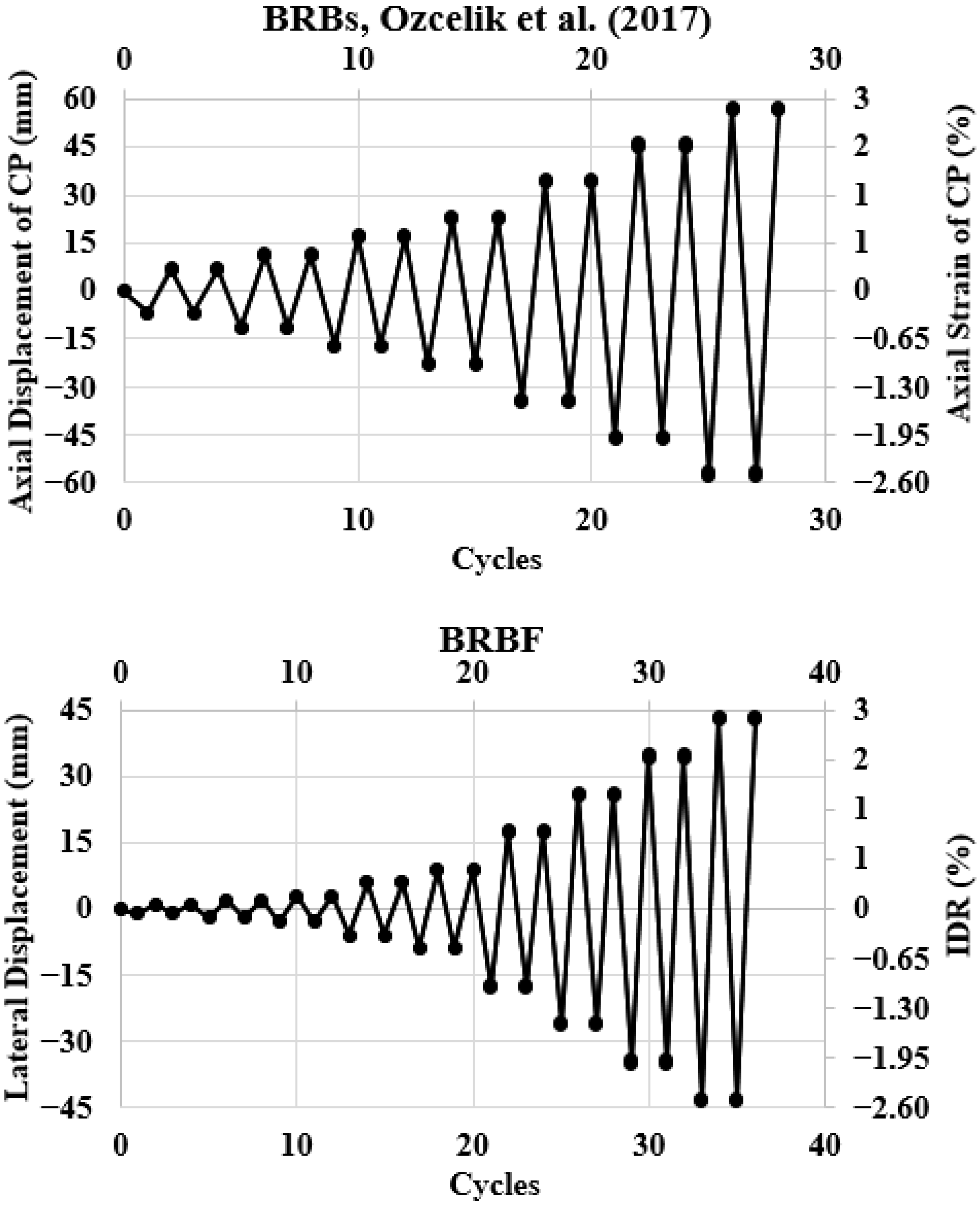
2.4. Loading Protocol
3. FE Study
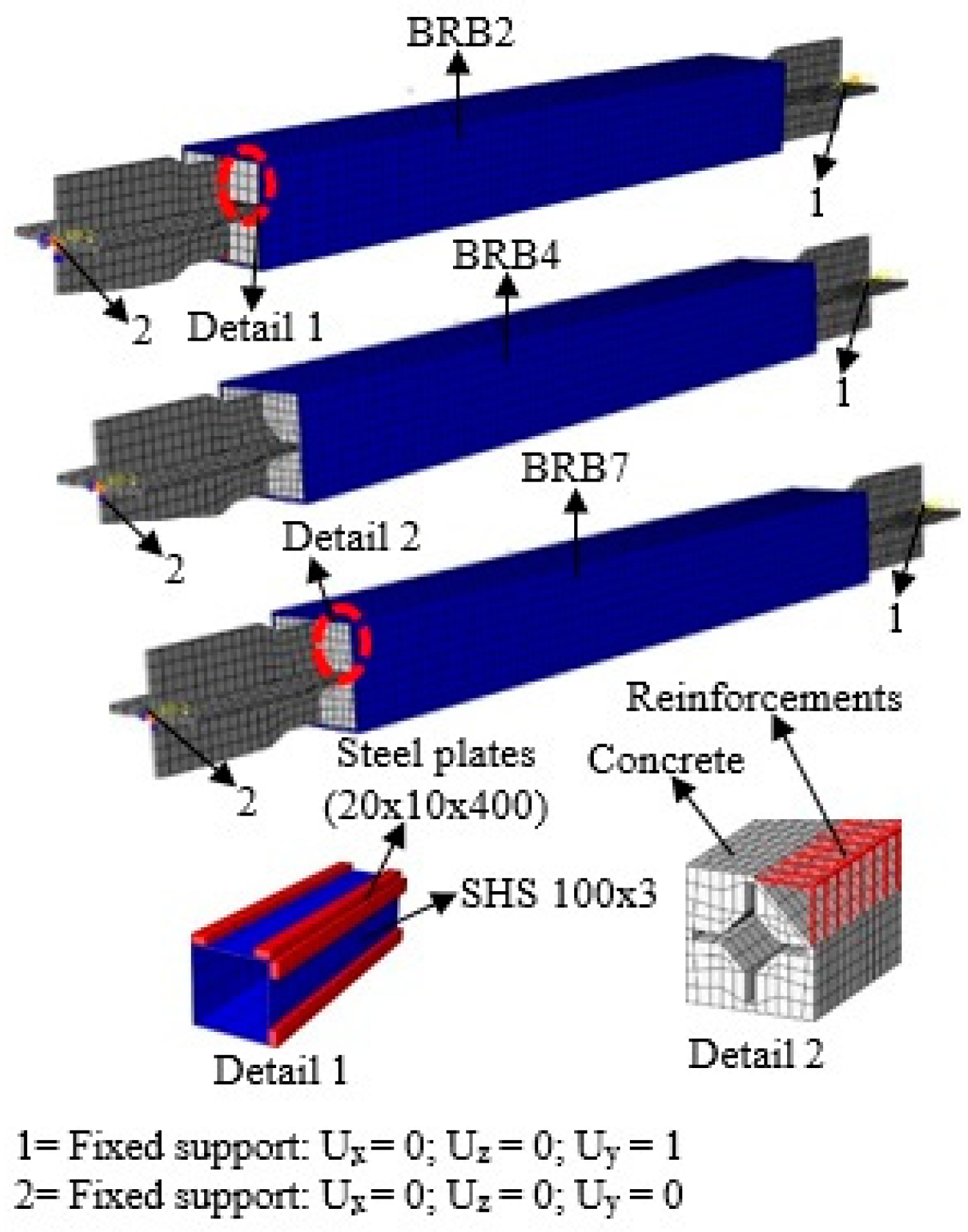
3.1. FEM of BRBs
3.2. FEM of Steel Frame
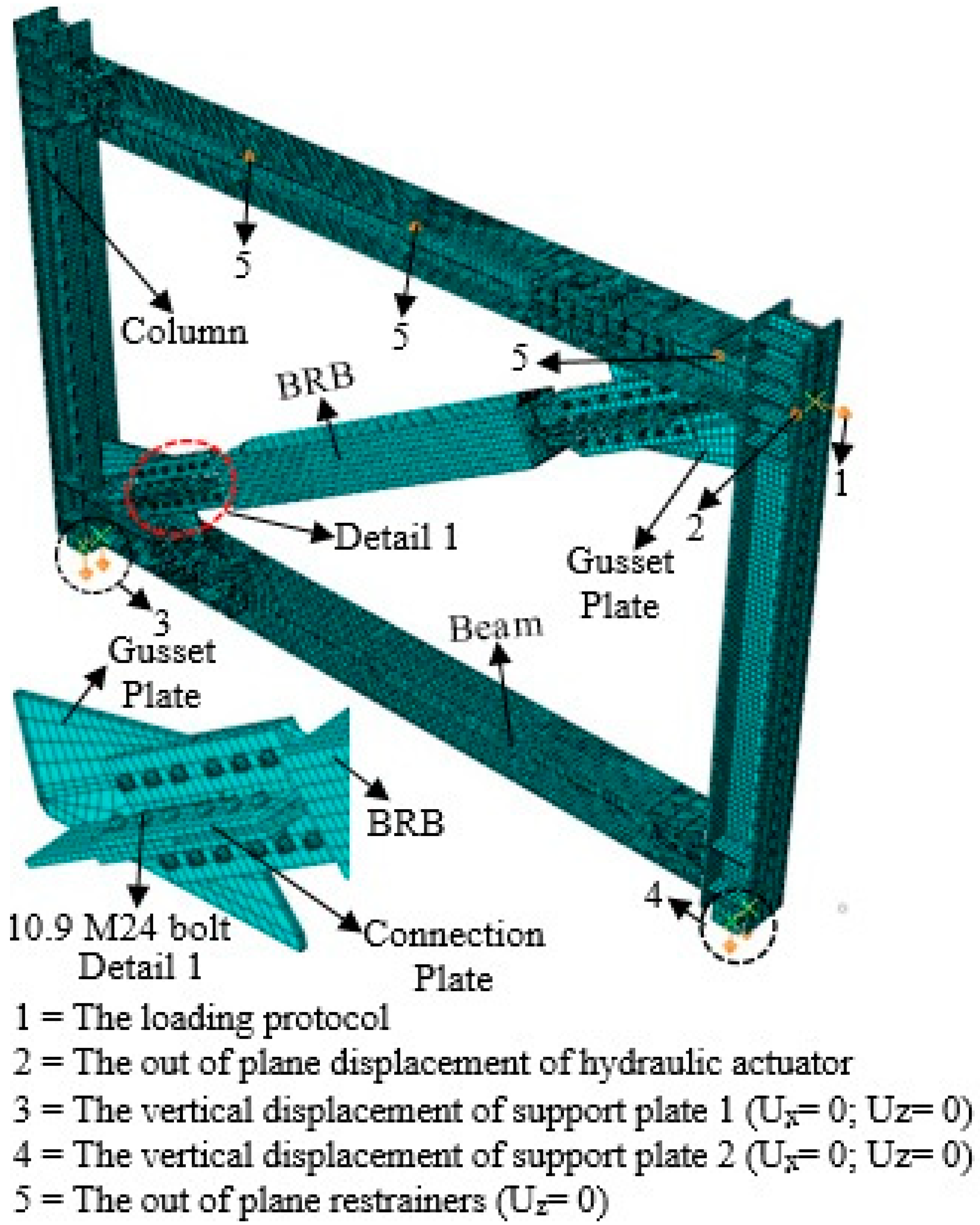
3.3. FEM of BRBF
4. Results and Discussion
4.1. Test Results
4.2. FEM Results
4.2.1. The BRBs
4.2.2. Steel Frame
4.2.3. The BRBF
4.3. Discussion
5. Conclusions
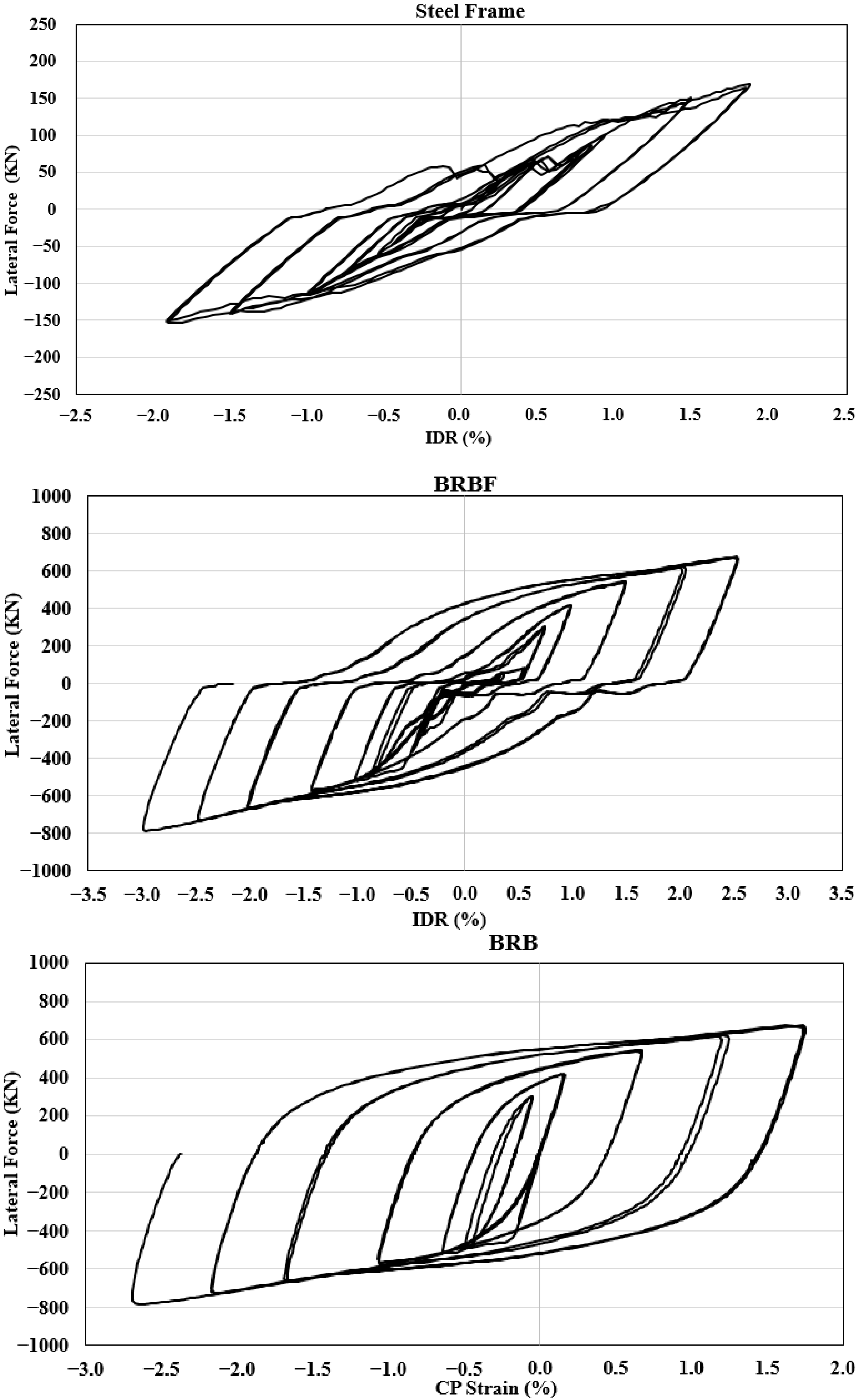
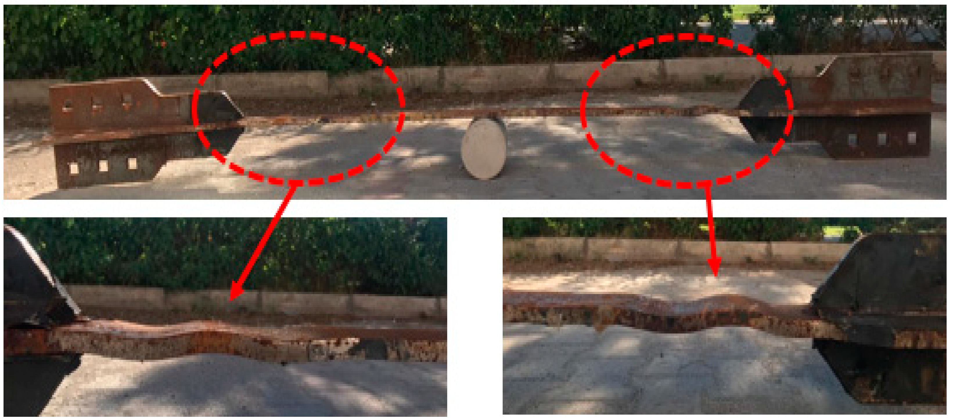
- Although the BRB inside the steel frame was subjected to 2.69% strain of the CP under the axial compression demands, local and global deformations were not observed. For this reason, it provided symmetrical hysteretic behavior to the steel frame. The construction details of the BRB are hence acceptable. This can be useful for further studies and design provisions.
- The test results indicated that the well-detailed BRBF can resist significant drift demands, while the BRB exhibited significant yielding without severe damage. This is important since BRBFs in critical applications where drift demands play a vital role can offer more resilience.
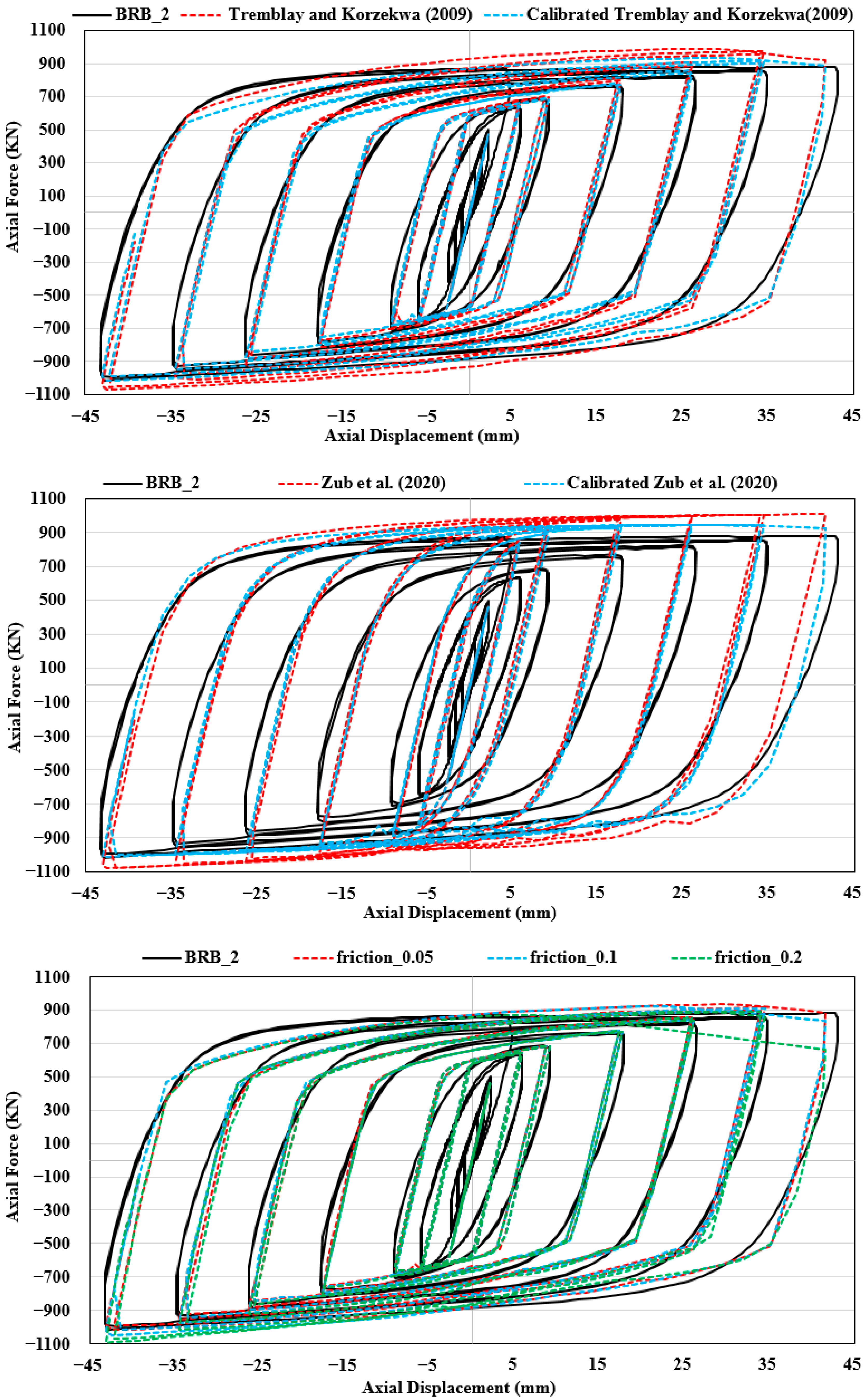
- The parametric study based on material parameters indicated that the isotropic and kinematic hardening parameters had a significant effect on the hysteretic behavior of the BRB. Therefore, a fatigue test needs to be performed together with coupon tests to determine material parameters of the CP. This approach can greatly enhance the resistance of BRB against dynamic loading as well as provide a safer design.
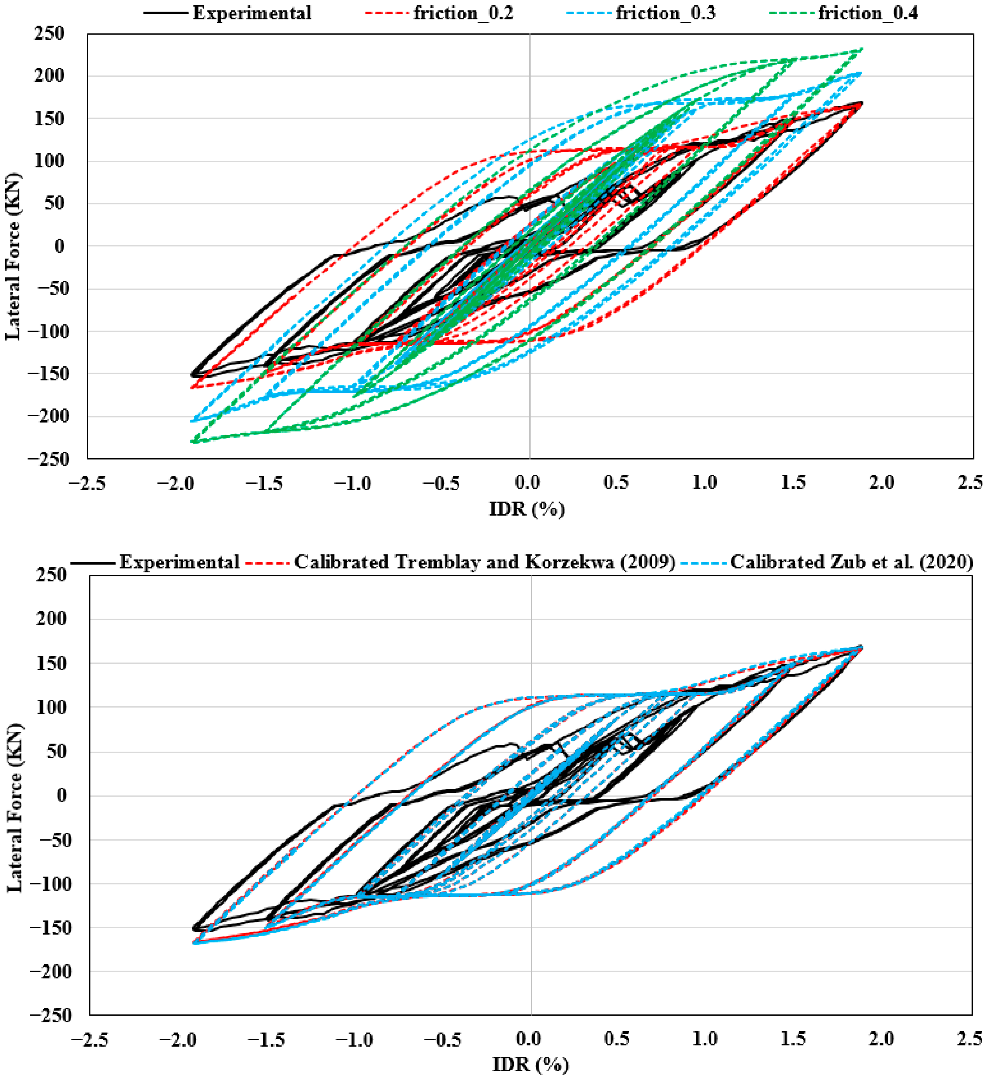
- The sufficient pretension load applied to bolts in the FEM of the steel frame resulted in no slip in the bolted connection. Therefore, the value of the friction coefficient was determined from the ultimate load capacity of the steel frame. The value of the friction coefficient between the contact surfaces of steel plates seems to be determined experimentally for further studies. Furthermore, the pretension load also has significant effects on the hysteretic behavior of the BRBF.
- The value of the friction coefficient between the CP and the CM in the FEMs of BRBs and between the contact surfaces of steel plates in the FEM of the steel frame was taken as 0.05 and 0.2, respectively. The best numerical results were obtained for the BRBs and the steel frame by using these values. In addition, while the pretension load of 75 kN provided the best numerical behavior for the BRBF under the compression demands, its behavior under the tension demands was obtained by the pretension load of 35 kN.
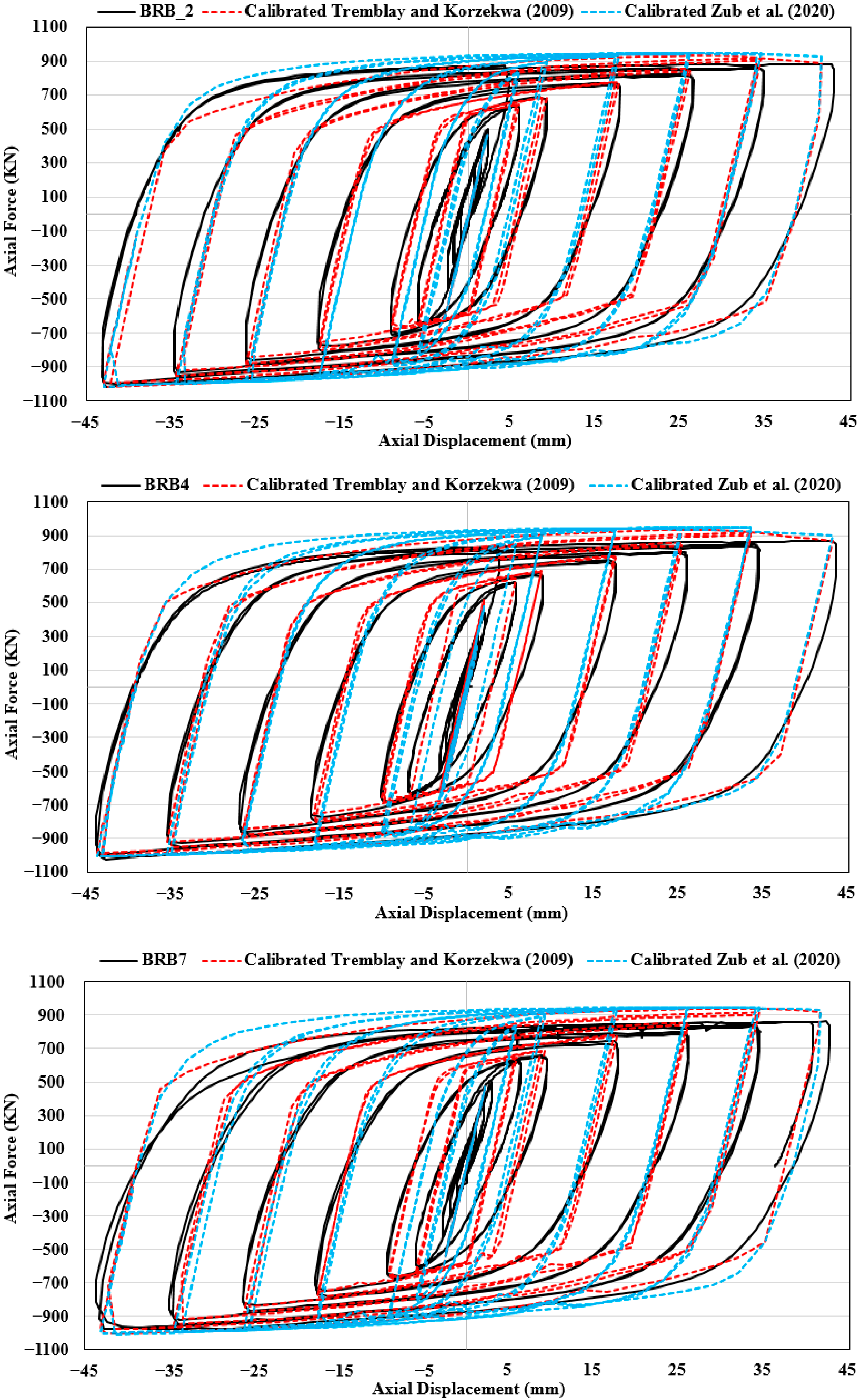
- The steel frame and BRBF were modeled by using a micro-modeling technique. The numerical results indicated that the numerical hysteretic behavior of the steel frame and BRBF was highly affected by the pretension load applied to bolts and the value of the friction coefficient between the contact surfaces of steel plates, which were parameters of micro-modeling techniques. Both calibrated material models by Korzekwa and Tremblay [46] and Zub et al. [36] provided approximately the same numerical hysteretic response for all the FEMs. The developed and validated FE model can be used as a tool to predict the structural behavior of BRBFs.
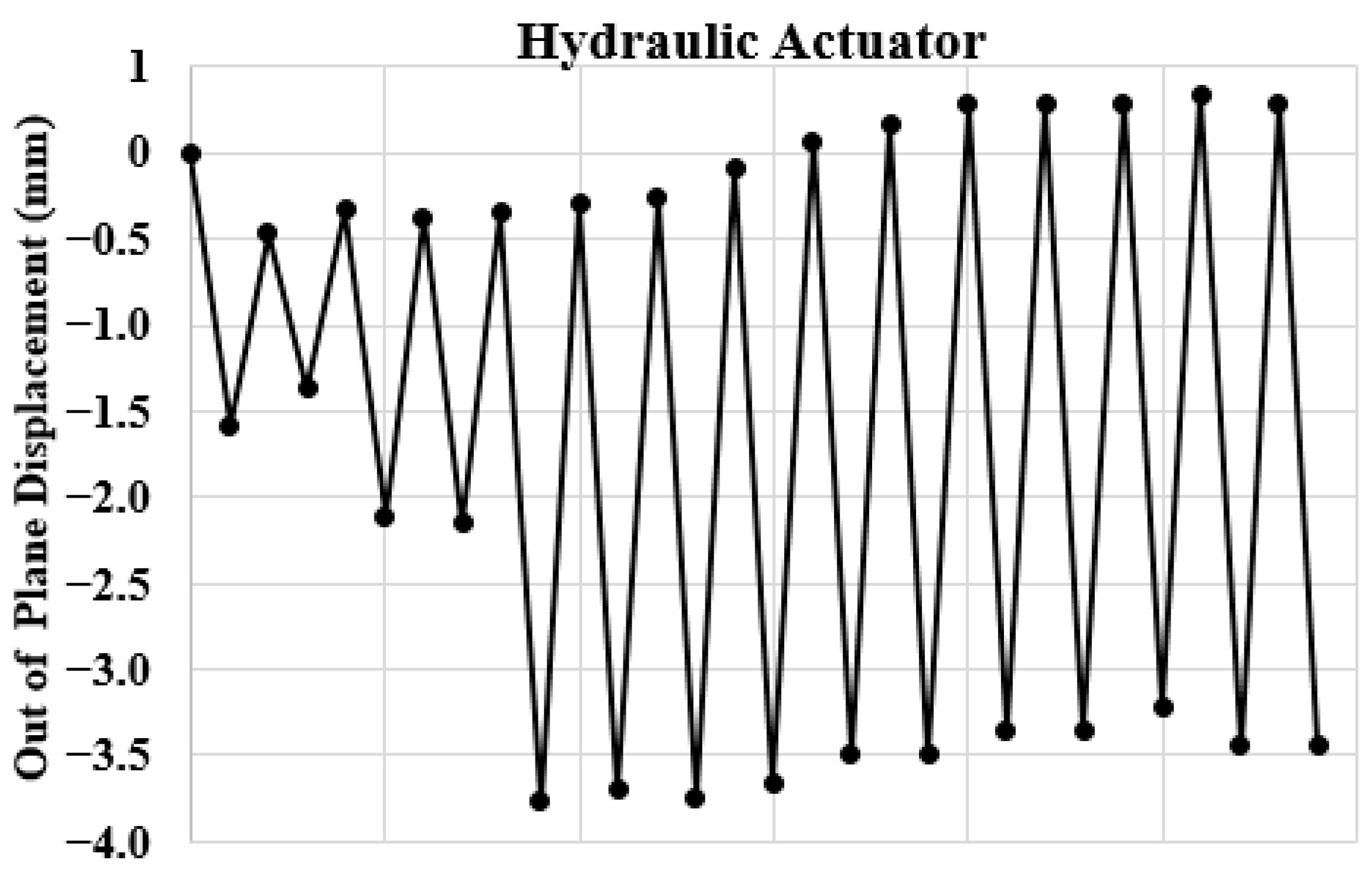
- The numerical investigations of the behavior of BRBF in the literature are generally focused on the friction between the CP and CM. This paper has demonstrated that the numerical behavior of the BRBF is significantly affected not only by the friction between the CP and CM but also by the friction between contact surfaces of steel plates in the slip-critical connections, the pretension load of bolts, vertical displacements of the support, and the out-of-plane displacements of the frame.
- In this study, the subassembly test of BRB, whose geometrical properties are identical to BRB4 tested by Ozcelik et al. [2], was performed. The test results demonstrated that the friction between CP and CM was acceptable and the BRB had stable hysteretic behavior. For this reason, it is thought that the BRB tested in this paper can constitute a basis for its practice as an energy damper in the structures.
Author Contributions
Funding
Institutional Review Board Statement
Informed Consent Statement
Data Availability Statement
Conflicts of Interest
References
- Black, R.G.; Wenger, W.A.B.; Popov, E.P. Inelastic Buckling of Steel Struts under Cyclic Load Reversal; Technical Report UCB/EERC-80/40; National Science Foundation: Alexandria, VA, USA, 1980.
- Ozcelik, R.; Dikiciasik, Y.; Erdil, E.F. The Development of the Buckling Restrained Braces with New End Restrains. J. Constr. Steel Res. 2017, 138, 208–220. [Google Scholar] [CrossRef]
- Iwata, M.; Kato, T.; Wada, A. Buckling-Restrained Braces as Hysteretic Dampers. In Proceedings of the STESSA, Quebec, PQ, Canada, 21–24 August 2000; pp. 33–38. [Google Scholar]
- Clark, P.; Aiken, I.; Kasai, K.; Ko, E.; Kimura, I. Design Procedures for Buildings Incorporating Hysteretic Damping Devices. In Proceedings of the International Post-SMiRT Conference, Cheju, Republic of Korea, 23–25 August 1999. [Google Scholar]
- Black, C.; Makris, N.; Aiken, I. Component Testing, Stability Analysis and Characterization of Buckling Restrained Braces; Pacific Earthquake Engineering Research Center: Berkeley, CA, USA, 2002. [Google Scholar]
- Hong, H.P.; Somo, S. Probabilistic Assessment of Pavement Conditions. Can. J. Civ. Eng. 2001, 28, 813–822. [Google Scholar] [CrossRef]
- Higgins, C.C.; Newell, J.D. Confined Steel Brace for Earthquake Resistance Design. AISC Eng. J. 2004, 4th, 187–202. [Google Scholar] [CrossRef]
- Ju, Y.K.; Kim, M.H.; Kim, J.; Kim, S.D. Component Tests of Buckling-Restrained Braces with Unconstrained Length. Eng. Struct. 2009, 31, 507–516. [Google Scholar] [CrossRef]
- Takeuchi, T.; Hajjar, J.F.; Matsui, R.; Nishimoto, K.; Aiken, I.D. Effect of Local Buckling Core Plate Restraint in Buckling Restrained Braces. Eng. Struct. 2012, 44, 304–311. [Google Scholar] [CrossRef]
- Eryasar, M.E.; Topkaya, C. An Experimental Study on Steel-Encased Buckling-Restrained Brace Hysteretic Dampers. Earthq. Eng. Struct. Dyn. 2010, 39, 561–581. [Google Scholar] [CrossRef]
- Tsai, K.C.; Hwang, Y.C.; Weng, C.S.; Shirai, T.; Nakamura, H. Experimental Tests of Large Scale Buckling Restrained Braces and Frames. In Proceedings of the Passive Control Symposium, Tokyo, Japan, 13–14 December 2002; Tokyo Institute of Technology: Tokyo, Japan, 2002. [Google Scholar]
- Tremblay, R.; Degrange, G. Blouin Seismic Rehabilitation of a Four-Storey Building with a Stiffened Bracing System. In Proceedings of the 8th Canadian Conference on Earthquake Engineering, Vancouver, Canada, 13–16 June 1999; pp. 549–554. [Google Scholar]
- Tremblay, R.; Bolduc, P.; Neville, R.; DeVall, R. Seismic Testing and Performance of Buckling-Restrained Bracing Systems. Can. J. Civ. Eng. 2006, 33, 183–198. [Google Scholar] [CrossRef]
- Uriz, P.; Mahin, S.A. Toward Earthquake-Resistant Design of Concentrically Braced Steel-Frame Structures; Pacific Earthquake Engineering Research Center: Berkeley, CA, USA, 2008. [Google Scholar]
- López, W.A.; Gwie, D.S.; Lauck, T.W.; Mark Saunders, C. Structural Design and Experimental Verification of a Buckling-Restrained Braced Frame System. Eng. J. 2004, 41, 177–186. [Google Scholar] [CrossRef]
- Merritt, S.; Uang, C.-M.; Benzoni, G. Subassemblage Testing of Starseismic Buckling-Restrainedbraces; University of California: Berkeley, CA, USA, 2003. [Google Scholar]
- Okazaki, T.; Hikino, T.; Kajiwara, K. Out-of-Plane Stability of Buckling-Restrained Braces. In Proceedings of the 15th World Conference Earthquake Engineering, Lisbon, Protugal, 24–28 September 2012. [Google Scholar]
- Hikino, T.; Okazaki, T.; Kajiwara, K.; Nakashima, M. Out-of-Plane Stability of Buckling-Restrained Braces Placed in Chevron Arrangement. J. Struct. Eng. 2013, 139, 1812–1822. [Google Scholar] [CrossRef]
- Kasai, K.; Ooki, Y.; Ishii, M.; Ozaki, H.; Ito, H.; Motoyui, S.; Hikino, T.; Sato, E. Value-Added 5-Story Steel Frame and Its Components: Part 1-Full-Scale Damper Tests and Analyses. In Proceedings of the 14th World Conference on Earthquake Engineering, Beijing, China, 12–17 October 2008. [Google Scholar]
- Christopulos, A.S. Improved Seismic Performance of Buckling Restrained Braced Frames; University of Washington: Seattle, WA, USA, 2005. [Google Scholar]
- Tsai, K.C.; Hsiao, P.C.; Wang, K.J.; Weng, Y.T.; Lin, M.L.; Lin, K.C.; Chen, C.H.; Lai, J.W.; Lin, S.L. Pseudo-Dynamic Tests of a Full-Scale CFT/BRB Frame—Part I: Specimen Design, Experiment and Analysis. Earthq. Eng. Struct. Dyn. 2008, 37, 1081–1098. [Google Scholar] [CrossRef]
- Tsai, K.C.; Hsiao, P.C. Pseudo-Dynamic Test of a Full-Scale CFT/BRB Frame—Part II: Seismic Performance of Buckling-Restrained Braces and Connections. Earthq. Eng. Struct. Dyn. 2008, 37, 1099–1115. [Google Scholar] [CrossRef]
- Mazzolani, F.M. Innovative Metal Systems for Seismic Upgrading of RC Structures. J. Constr. Steel Res. 2008, 64, 882–895. [Google Scholar] [CrossRef]
- Di Sarno, L.; Manfredi, G. Seismic Retrofitting of Existing RC Frames with Buckling Restrained Braces. In Improving the Seismic Performance of Existing Buildings and Other Structures—Proceedings 2009 ATC and SEI Conference on Improving the Seismic Performance of Existing Buildings and Other Structures, San Francisco, CA, USA, 9–11 December 2009; Amer Society of Civil Engineers: Reston, VA, USA, 2009; pp. 741–752. [Google Scholar]
- Parry Brown, A.; Aiken Ian, D.; Jafarzadeh, F.J. Buckling Restrained Braces Provide the Key to the Seismic Retrofit of the Wallace F. Bennett Federal Building. Mod. Steel Constr. 2001, 41, 29–37. [Google Scholar]
- Wu, K.; Wei, G.; Lin, C.; Zhang, L.; Yu, W.; Lan, X. Experimental Study on the Seismic Performance of Buckling-Restrained Braces with Different Lengths. Buildings 2025, 15, 154. [Google Scholar] [CrossRef]
- Alemayehu, R.W.; Kim, Y.; Park, M.J.; Park, M.; Ju, Y.K. Experimental and Finite Element Study of Polymer Infilled Tube-in-Tube Buckling Restrained Brace. Metals 2021, 11, 1358. [Google Scholar] [CrossRef]
- Li, J.; Sun, H.; Guo, L.; Wang, Y.; Zhang, S. Experimental Investigation on Seismic Behavior of Composite Frames without and with BRBs. Structures 2025, 71, 108050. [Google Scholar] [CrossRef]
- Oyguc, E.; Oyguc, R.; Seker, O.; Hayir, A.; Shen, J.; Akbas, B. Improving Seismic Performance of RC Structures with Innovative TnT BRBs: A Shake Table and Finite Element Investigation. Appl. Sci. 2025, 15, 3844. [Google Scholar] [CrossRef]
- Lu, J.; Ji, P.; Cheng, P.; Xu, G. Numerical Study on Seismic Performance of Buckling-Restrained Braced Double-Pier RC Bridge with Bolted Gusset Connections. Appl. Sci. 2023, 13, 4391. [Google Scholar] [CrossRef]
- Chen, R.; Qiu, C.; Hao, D. Seismic Response Analysis of Multi-Story Steel Frames Using BRB and SCB Hybrid Bracing System. Appl. Sci. 2019, 10, 284. [Google Scholar] [CrossRef]
- Naqi, A.; Roy, T.; Saito, T. Time-Dependent Damage Estimation of a High-Rise Steel Building Equipped with Buckling-Restrained Brace under a Series of Earthquakes and Winds. Appl. Sci. 2021, 11, 9253. [Google Scholar] [CrossRef]
- Li, X.M.; Liu, Y.; Wu, H.; Ding, C.Y.; Dong, J.; Peng, W.; Zhang, D.H.; Sun, J. A Comprehensive Analytical Model for Tensile-Bending Straightening in Strip Processing by Coupling Residual Stress and Buckling Deformation. J. Mater. Process. Technol. 2025, 339, 118802. [Google Scholar] [CrossRef]
- Yao, S.; Chen, Y.; Sun, C.; Zhao, N.; Wang, Z.; Zhang, D. Dynamic Response Mechanism of Thin-Walled Plate under Confined and Unconfined Blast Loads. J. Mar. Sci. Eng. 2024, 12, 224. [Google Scholar] [CrossRef]
- AlHamaydeh, M.; Abed, F.; Mustapha, A. Key Parameters Influencing Performance and Failure Modes for BRBs Using Nonlinear FEA. J. Constr. Steel Res. 2016, 116, 1–18. [Google Scholar] [CrossRef]
- Zub, C.I.; Stratan, A.; Dubina, D.; Zub, C.I.; Stratan, A.; Dubina, D. Steel and Composite Structures. Steel Compos. Struct. 2020, 34, 561. [Google Scholar]
- Pandikkadavath, M.S.; Sahoo, D.R. Analytical Investigation on Cyclic Response of Buckling-Restrained Braces with Short Yielding Core Segments. Int. J. Steel Struct. 2016, 16, 1273–1285. [Google Scholar] [CrossRef]
- Guo, Y.L.; Tong, J.Z.; Wang, X.A.; Zhang, B.H. Subassemblage Tests and Numerical Analyses of Buckling-Restrained Braces under Pre-Compression. Eng. Struct. 2017, 138, 473–489. [Google Scholar] [CrossRef]
- ABAQUS. ABAQUS 6.14 Analysis and Theory Manual; Dassault Systemes Simulia Corp.: Santa Clara, CA, USA, 2014. [Google Scholar]
- Hoveidae, N.; Rafezy, B. Overall Buckling Behavior of All-Steel Buckling Restrained Braces. J. Constr. Steel Res. 2012, 79, 151–158. [Google Scholar] [CrossRef]
- Ghowsi, A.F.; Sahoo, D.R. Effect of Loading History and Restraining Parameters on Cyclic Response of Steel BRBs. Int. J. Steel Struct. 2019, 19, 1055–1069. [Google Scholar] [CrossRef]
- Chou, C.C.; Chen, S.Y. Subassemblage Tests and Finite Element Analyses of Sandwiched Buckling-Restrained Braces. Eng. Struct. 2010, 32, 2108–2121. [Google Scholar] [CrossRef]
- Turkish Government. Turkish Steel Design Code. In Calculation and Construction Details for Steel Structure; Resmi Gazete; Turkish Government: Ankara, Turkey, 2018. [Google Scholar]
- AISC (American Institute of Steel Construction). Seismic Provisions for Structural Steel Building; American Institute of Steel Construction: Chicago, IL, USA, 2005. [Google Scholar]
- Thornton, W.A. Bracing Connections for Heavy Construction. Eng. J. Am. Inst. Steel Constr. 1984, 21, 139–148. [Google Scholar] [CrossRef]
- Korzekwa, A.; Tremblay, R. Numerical Simulation of the Cyclic Inelastic Behaviour of Buckling Restrained Braces. In Proceedings of the STESSA, Philadelphia, PA, USA, 16–20 August 2009; pp. 653–658. [Google Scholar]
- Shi, Y.; Wang, M.; Wang, Y. Analysis on Shear Behavior of High-Strength Bolts Connection. Int. J. Steel Struct. 2011, 11, 203–213. [Google Scholar] [CrossRef]
- Lacey, A.W.; Chen, W.; Hao, H.; Bi, K. Experimental and Numerical Study of the Slip Factor for G350-Steel Bolted Connections. J. Constr. Steel Res. 2019, 158, 576–590. [Google Scholar] [CrossRef]
- Chen, Y.; Yamaguchi, T.; Hayashi, G.; Yamauchi, M.; Ueno, K. Mechanical Behavior of Hybrid Joint with Bearing-Type and Slip-Critical Bolted Connections. J. Constr. Steel Res. 2023, 211, 108172. [Google Scholar] [CrossRef]
- Xie, J.; Zhang, W. Numerical Analysis on Steel Bracing Members with Bolted Gusset Plate Connections. J. Constr. Steel Res. 2024, 222, 108960. [Google Scholar] [CrossRef]
- Bursi, O.S.; Jaspart, J.P. Basic Issues in the Finite Element Simulation of Extended End Plate Connections. Comput. Struct. 1998, 69, 361–382. [Google Scholar] [CrossRef]
- Bursi, O.S.; Jaspart, J.P. Calibration of a Finite Element Model for Isolated Bolted End-Plate Steel Connections. J. Constr. Steel Res. 1997, 44, 225–262. [Google Scholar] [CrossRef]
- Soo Kim, T.; Kuwamura, H. Finite Element Modeling of Bolted Connections in Thin-Walled Stainless Steel Plates under Static Shear. Thin-Walled Struct. 2007, 45, 407–421. [Google Scholar] [CrossRef]
- Li, J.; He, Q.; Zhang, K.; Lin, Z.; Ding, M.; Ju, J. Slipping Coefficient Study of Frictional High Strength Bolt Joint. Comput. Model. New Technol. 2014, 18, 133–137. [Google Scholar]
- Huang, Y.; Tian, H.; Wang, X.; Wang, Y.; Yang, H. The Effects of Secondary Pre-Tightening of the Clamping Cable Nodes on Yielding U-Shaped Steel Supports for Use in Deep Soft Rock Roadways. Appl. Sci. 2025, 15, 3803. [Google Scholar] [CrossRef]
- Guo, H.; Xiao, F.; Liu, Y.; Liang, G. Experimental and Numerical Study on the Mechanical Behavior of Q460D High-Strength Steel Bolted Connections. J. Constr. Steel Res. 2018, 151, 108–121. [Google Scholar] [CrossRef]
- Abdelrahman, A.H.A.; Liu, Y.P.; Chan, S.L. Advanced Joint Slip Model for Single-Angle Bolted Connections Considering Various Effects. Adv. Struct. Eng. 2020, 23, 2121–2135. [Google Scholar] [CrossRef]
- Khandel, O.; Tamimi, M.F.; Soliman, M.; Russell, B.W.; Waite, C.D. Reliability Assessment of Connections with Slip-Critical Bolts and Fillet Welds in Combination. J. Constr. Steel Res. 2022, 188, 107036. [Google Scholar] [CrossRef]
- Lyu, Y.F.; Li, G.Q.; Wang, Y.B.; Li, H.; Wang, Y.Z. Effect of Bolt Pre-Tension on the Bearing Behavior of High Strength Steel Connections. Eng. Struct. 2021, 241, 112491. [Google Scholar] [CrossRef]
- Han, Q.; Li, Y.; Lu, Y.; Wang, P. Effect of Faying Surface Treatments and Bolt Tightened Levels on Fretting Fatigue Performance of Slip Critical Connections with High Strength Bolts. Tribol. Int. 2025, 201, 110257. [Google Scholar] [CrossRef]
- Jiang, K.; Li, S.; Zhong, Y.; Zhao, O. Bearing–Curling Interaction of Austenitic Stainless Steel Thin Sheet Bolted Connections. Thin-Walled Struct. 2024, 200, 111912. [Google Scholar] [CrossRef]
- Kim, J.; Yoon, J.C.; Kang, B.S. Finite Element Analysis and Modeling of Structure with Bolted Joints. Appl. Math. Model. 2007, 31, 895–911. [Google Scholar] [CrossRef]
- Shi, Y.; Wang, M.; Wang, Y. Experimental and Constitutive Model Study of Structural Steel under Cyclic Loading. J. Constr. Steel Res. 2011, 67, 1185–1197. [Google Scholar] [CrossRef]
- Ostovar, N.; Hejazi, F. Buckling-Restrained Bracing System with Ultra-High-Performance Fiber Concrete. Appl. Sci. 2023, 13, 8250. [Google Scholar] [CrossRef]
- Jia, M.; Chen, Y.; Jin, P. Development and Validation Analysis of a Steel-Lead Hybrid Dual-Yield BRB for Multi-Stage Seismic Energy Dissipation. Thin-Walled Struct. 2024, 199, 111822. [Google Scholar] [CrossRef]
- Yu, X.Y.; Li, Y.W.; Zhao, J.; Zhao, X.Y. A Unified Low Cycle Fatigue Model of Axial-Loaded Buckling-Restrained Fe-SMA Plates in High-Performance Metallic Dampers. Eng. Struct. 2025, 325, 119461. [Google Scholar] [CrossRef]


| Spec. No. | End Restrainers | Thickness of Rubber | Area (mm2) | ||
|---|---|---|---|---|---|
| Cruciform Sec. | Cruciform Sec. | CP | |||
| Section A-A | Section B-B | Section C-C | |||
| BRB2 [2] | 40 cm-SHS 100 × 3 | 4 | 7875 | 6375 | 2250 |
| BRB4 [2] | 40 cm-Steel Plates | 4 | 7875 | 6375 | 2250 |
| BRB7 [2] | 40 cm-Steel Plates | 4 | 7875 | 6375 | 2250 |
| BRB * | 40 cm-Steel Plates | 4 | 7875 | 4875 | 1500 |
| Material Model | Kinematic Hardening Parameters (Mpa) | Isotropic Hardening Parameters (Mpa) | |||||||||||
|---|---|---|---|---|---|---|---|---|---|---|---|---|---|
| σ0 | C1 | γ1 | C2 | γ2 | C3 | γ3 | C4 | γ4 | C5 | γ5 | Q∞ | b | |
| Korzekwa and Tremblay [46] | 270 | 8000 | 75 | - | - | - | - | - | - | - | - | 110 | 4 |
| Zub et al. [36] | 270 | 95,000 | 1300 | 40,500 | 680 | 5000 | 120 | 500 | 2.5 | 200 | 2 | - | - |
| Calibrated Korzekwa and Tremblay [46] | 270 | 8000 | 75 | - | - | - | - | - | - | - | - | 110 | 2 |
| Calibrated Zub et al. [36] | 270 | 87,000 | 1300 | 32,500 | 680 | 4600 | 120 | 275 | 2.5 | 160 | 2 | - | - |
| Components | Young’s Modulus (MPa) | Poisson’s Ratio | Fy (MPa) | Fu (MPa) | fc (MPa) |
|---|---|---|---|---|---|
| CP | 210,000 | 0.3 | 270 | 401 | - |
| SHS 250X6 | 210,000 | 0.3 | 235 | - | - |
| SHS 100X3 | 210,000 | 0.3 | 235 | - | - |
| Concrete | 25,000 | 0.2 | - | - | 25 |
| Slip (mm) | Out-of-Plane Displacement (mm) | |||||
|---|---|---|---|---|---|---|
| LVDTs (in Figure 6) | LVDTs (in Figure 6) | |||||
| 10 | 11 | 12 | 13 | 16 | 17 | |
| Max. | 0.065 | 0.075 | 0.098 | 0.08 | 1.08 | 1.08 |
| Min. | −0.005 | −0.033 | −0.048 | −0.072 | −1.06 | −1.06 |
| Demands | Calibrated Korzekwa and Tremblay [46] | Calibrated Zub et al. [36] | ||||||||
|---|---|---|---|---|---|---|---|---|---|---|
| Tension | IDR | Max. Lateral Force (KN) | Error | R2 | Drift Ratio | Max. Lateral Force (KN) | Error | R2 | ||
| Exp. | Num. | Exp. | Num. | |||||||
| 1.00% | 471 | 529 | 12.31% | 92.21% | 1.00% | 471 | 546 | 15.92% | 87.36% | |
| 1.50% | 592 | 638 | 7.77% | 1.50% | 592 | 627 | 5.91% | |||
| 2.00% | 617 | 624 | 1.13% | 2.00% | 617 | 633 | 2.59% | |||
| 2.50% | 677 | 669 | 1.18% | 2.50% | 677 | 668 | 1.33% | |||
| Compression | 1.00% | 576 | 585 | 1.56% | 1.00% | 576 | 651 | 13.02% | ||
| 1.50% | 612 | 652 | 6.54% | 1.50% | 612 | 678 | 10.78% | |||
| 2.00% | 660 | 683 | 3.48% | 2.00% | 660 | 697 | 5.61% | |||
| 2.50% | 737 | 718 | 2.57% | 2.50% | 737 | 719 | 2.44% | |||
| 3.00% | 788 | 726 | 7.87% | 3.00% | 788 | 735 | 6.73% | |||
Disclaimer/Publisher’s Note: The statements, opinions and data contained in all publications are solely those of the individual author(s) and contributor(s) and not of MDPI and/or the editor(s). MDPI and/or the editor(s) disclaim responsibility for any injury to people or property resulting from any ideas, methods, instructions or products referred to in the content. |
© 2025 by the authors. Licensee MDPI, Basel, Switzerland. This article is an open access article distributed under the terms and conditions of the Creative Commons Attribution (CC BY) license (https://creativecommons.org/licenses/by/4.0/).
Share and Cite
Sogut, H.; Ozcelik, R.; Sogut, K.; Erdal, F. Experimental Behavior and FE Modeling of Buckling Restrained Braced Frame with Slip-Critical Connection. Appl. Sci. 2025, 15, 5626. https://doi.org/10.3390/app15105626
Sogut H, Ozcelik R, Sogut K, Erdal F. Experimental Behavior and FE Modeling of Buckling Restrained Braced Frame with Slip-Critical Connection. Applied Sciences. 2025; 15(10):5626. https://doi.org/10.3390/app15105626
Chicago/Turabian StyleSogut, Huseyin, Ramazan Ozcelik, Kagan Sogut, and Ferhat Erdal. 2025. "Experimental Behavior and FE Modeling of Buckling Restrained Braced Frame with Slip-Critical Connection" Applied Sciences 15, no. 10: 5626. https://doi.org/10.3390/app15105626
APA StyleSogut, H., Ozcelik, R., Sogut, K., & Erdal, F. (2025). Experimental Behavior and FE Modeling of Buckling Restrained Braced Frame with Slip-Critical Connection. Applied Sciences, 15(10), 5626. https://doi.org/10.3390/app15105626