Abstract
In this study, to optimize the lightweight design of power battery cases for new energy vehicles and meet impact resistance requirements, the mechanical properties of honeycomb sandwich composites were experimentally investigated by varying carbon/glass fiber hybrid ratios. Carbon fiber and glass fiber hybrid laminates were used as the panel, and the aluminum honeycomb was used as the core layer to prepare sandwich composite materials through vacuum-assisted resin infusion (VARI). Then, the flexural and impact properties of honeycomb sandwich composites with different hybrid ratios were tested, respectively. The damage morphology and the damage mechanism of the hybrid composites were analyzed by 3D profile scanning. The results demonstrated that compared to glass fiber-reinforced panels, hybrid panels significantly enhanced the flexural load-bearing capacity of the sandwich composites, exhibiting maximum increases of 26.5% and 34.38% in the L direction and W direction, respectively. Carbon fiber effectively improved the impact resistance of specimens, with the maximum impact load increasing by 53.09% and energy absorption showing measurable enhancement, while glass fiber improves toughness and reduces the severity of damage. This study includes damage analysis and mechanical behavior change analysis of composite materials, which can provide a reference for the application of composite materials in the battery box shell.
1. Introduction
The honeycomb structure, as a bionic design mimicking the hexagonal architecture of natural honeycombs, demonstrates a high strength-to-weight ratio [1,2], excellent flexural and compressive rigidity, and enhanced stability compared to homogeneous solid plates of equivalent mass. Aluminum honeycomb [3,4] is a composite sheet [5,6] made of aluminum alloy material with good bending stiffness. The bending stiffness of the same quality aluminum honeycomb plate is about 5 times that of aluminum alloy. The honeycomb structure composites are widely used in aerospace, transportation, construction, packaging, furniture manufacturing, and other fields [7,8,9,10].
With global environmental protection gradually gaining attention, new energy is also developing rapidly [11,12,13]. This change has put forward higher requirements for the battery box, promoting the battery box in terms of material, structure, performance, and other aspects of innovation and improvement [14]. Lightweighting new energy vehicle battery casings through new materials and structural optimization is the mainstream approach. Casing materials have transitioned from steel dominance to a new era featuring steel–aluminum hybrids, full aluminum alloys, magnesium–aluminum alloys, and fiber-reinforced composites. In response to the concept of energy saving and environmental protection, Zhao et al. [15] proposed a new BF/PLA composite battery box. The mechanical properties of the BF/PLA composite were tested, and subsequently, the static analysis and constraint modal analysis of the traditional metal battery box were carried out under the typical working conditions of rapid turning and braking under vertical bumping. Compared with traditional metal battery enclosures under identical operating conditions, the composite battery box demonstrates enhanced reliability, showing improved performance in flammability resistance [16], corrosion tolerance [17], temperature stability [18], and crashworthiness [19], while maintaining compliance with rigidity and strength requirements across diverse operational scenarios. In addition, Zhao et al. [20] also proposed a honeycomb sandwich battery box composed of a high-strength steel outer layer, an aluminum alloy honeycomb sandwich, and an inner layer. At the same time, aluminum alloy honeycomb samples were made to verify the accuracy of the finite element simulation and theoretical model under quasi-static compression. Then, the optimum thickness of the three-layer plate was optimized under the constraint condition that the first mode frequency is greater than 30 Hz. Finally, the mass of the optimized battery box was reduced by 37.26%, and its static performance was greatly improved compared with the traditional battery box.
The common battery box shell is mainly composed of carbon fiber [21,22] and glass fiber [23], and its hybrid ratio affects the mechanical properties of the battery box shell, such as impact and bending [24,25]. Li et al. [26] studied the effect of mixing on the vibration response of carbon/glass hybrid composite laminates by using analytical and numerical models. They studied nine types of four-layer hybrid composite laminates, and studied in detail the effects of layering sequence, material properties, and geometry on vibration response. The results show that the natural frequency increases with the increase in the mixing ratio due to the increase in the stiffness of the composite laminates. Hasan Ikbal et al. [27] compared the properties of intralayer and interlayer hybrid materials with carbon/epoxy and glass/epoxy composites. It was found that the intralayer hybrid showed better compression performance than that of the interlayer hybrid; in addition, percentage enhancement in compressive failure strain was noticed. Negative hybrid effects on compressive strength were noticed for both intralayer and interlayer hybrid configurations. Shi et al. [28] studied the low-speed impact behavior of intralayer hybrid carbon/glass braided composite pipes under internal pressure. The effects of intralayer fiber arrangement and internal pressure on mechanical response, damage propagation, and material cost-effectiveness were analyzed. It was found that yarn splitting of brittle carbon fiber and ductile glass fiber can induce in-yarn unsticking and delamination damage to prevent each other, and it easily produces out-of-plane displacement and shear stress under impact load. Hu et al. [29] found that the fracture energy and delamination degree of the center carbon fiber layer could be controlled by adjusting the structural parameters to design the pseudo-ductility of carbon/glass (C/G) hybrid laminates and obtain the higher pseudo-yield stress. The highlights revealed the pseudo-ductility behavior of carbon/glass hybrid composites. The pseudo-ductility of carbon/glass hybrid composites is controllable. The pseudo-ductility strain increases with the increase in C/G ratio.
The smaller hybrid fiber alternating unit avoids the aggregation of pure reinforced fiber material under the impactor, which is conducive to the hybrid impact toughening effect. The aluminum honeycomb panel plays an increasingly important role in modern industry due to its unique structure and performance, especially in the pursuit of lightweight and environmental protection. However, research on the mechanical properties of aluminum honeycomb sandwich panels remains limited both domestically and internationally. Nguyen et al. [30] developed a finite element model based on higher-order shear deformation theory to investigate the free vibration and low-velocity impact transient response of doubly curved shallow sandwich shells integrated with laminated three-phase polymer/GNP/fiber face sheets and an auxetic honeycomb core resting on elastic foundations, unveiling the coupling mechanisms between material parameters and impact loads on the structure’s dynamic behavior. William et al. [31] systematically investigated pre-implanted core damage effects on aluminum honeycomb-reinforced composite sandwich structures through integrated experimental and numerical approaches. Quasi-static flexural/compression testing protocols quantified core damage-induced degradation in shear modulus (G) and Young’s modulus (E). Mechanical characterization reveals that the carbon/glass hybrid ratio directly modulates bending–impact performance synergies, necessitating further exploration of hybrid configuration effects on multifunctional carbon–glass honeycomb sandwich panels.
In this paper, the mechanical behavior of aluminum honeycomb panels was studied deeply on the basis of the previous study. Based on the VARI molding process, sandwich structural composite faces were prepared by carbon plain weave fiber as the surface layer, glass fiber plain weave fabric as the core layer, and epoxy resin as the matrix, and then the carbon/glass mixed sandwich composite was prepared by bonding it with AL honeycomb core. Four kinds of samples with different hybrid ratios [32] were prepared, the effects of different hybrid ratios on the bending and low-velocity impact properties were analyzed. This study includes damage analysis and mechanical behavior change analysis of composite materials, which can provide a reference for the application of composite materials in the battery box shell.
2. Material and Characterization
2.1. Material
In this study, carbon fiber and glass fiber plain preform were provided by Wuxi Shengtai Carbon Fiber Products Co., Ltd. (Wuxi, China), and Anqing Kaful New Material Technology Co., Ltd. (Anqing, China), respectively. The aluminum honeycomb cores were provided by Foshan Shunde District Huiyu Honeycomb Material Co., Ltd. (Foshan, China). The specific performance parameters of fiber and honeycomb core are shown in Table 1 and Table 2. The epoxy resin matrix with curing agent (mass ratio of 100:30) was provided by No. 1 Advanced Materials Co., Ltd. (Shenzhen, China). The aluminum honeycomb-to-face sheet interfaces were bonded using N6292N0-20 epoxy adhesive film, provided by Luchen Advanced Materials Co., Ltd. (Chengdu, China).

Table 1.
Performance parameters of plain fabric.
Table 2.
Performance parameters of honeycomb cores.
2.2. Composite Preparation
In this paper, the mass ratio of carbon fiber in the hybrid fiber reinforcement system was used as the hybrid ratio, and the hybridization was carried out according to the hybridization method shown in Table 3 and Figure 1, where “C” and “G”, respectively, represent carbon fiber preform and glass fiber preform. The hybrid ratio calculation accounts solely for the areal density of fiber layers. Then, the composite laminate was prepared with epoxy resin by the vacuum-assisted resin infiltration (VARI) molding process. Finally, the composites bonded with laminate served as the face panel and the honeycomb served as the core layer.
Table 3.
Hybrid ratio and stacking sequence.
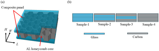
Figure 1.
Sample diagram and hybrid scheme: (a) sample diagram; (b) hybrid scheme.
2.3. Testing and Characterization
Three-point bending tests were performed on a Shimadzu (Kyoto, Japan) AGS-100kN universal testing machine in accordance with ASTM C393/C393M-20 [33]. The size of the sample was 200 × 75 × 12.5 mm, and the span ratio was 16. The loading speed was 2 mm/min, and five specimens of each composite were tested. The impact property was tested by a T752Z-OM-202111A drop hammer device (Shenzhen, China). Following the standard of ASTM D7136/D7136M-20 [34], the size of the sample was 150 × 100 × 12.5 mm, and 30 J was selected as the impact energy.
3. Results and Discussions
3.1. Bending Properties
The three-point bending load–displacement curve of the samples with different hybrid ratios are shown in Figure 2. According to the load–displacement curve of the three-point bending of the sample in Figure 2, it can be seen that the tensile process of the sample node is divided into three stages, namely, the elastic stage, the plastic stage, and the sudden change stage of the strength peak. When the indenter begins to contact the specimen, the specimen begins to bear the load; at this time, it is in the elastic stage, and the specimen does not appear to have any damage. With the increase in load, the specimen enters the plastic stage, cracks begin to appear on the surface of the sample, and the sample begins to show irreversible damage, as shown in Figure 2a. When the applied load reaches the peak value, the load carried by the sample drops sharply, and the sample fails under severe damage (Figure 2a). Because of the existence of the honeycomb core, the sample still has a certain carrying capacity after the load redistribution, which is shown in Figure 2b,c.
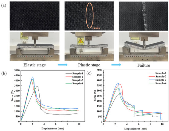
Figure 2.
The three-point bending load–displacement curve of samples with different hybrid ratios: (a) sample damage in the bending process; (b) bending load–displacement curve in the L direction; (c) bending load–displacement curve in the W direction.
As demonstrated in Figure 3a,d, the progressive addition of carbon fibers significantly enhances the flexural performance of hybrid composites. When the carbon/glass fiber hybrid ratio increases incrementally from 0 to 1, the longitudinal (L) direction (Figure 3a) exhibits peak load improvements of 16.21% (S-2), 26.54% (S-3), and 19.88% (S-4), accompanied by energy absorption (EA) enhancements (Figure 3b) from 11.62 J (S-1) to 14.20 J (S-2), 17.18 J (S-3), and 15.49 J (S-4), corresponding to increases of 22.20%, 47.85%, and 33.30%, respectively. The specific energy absorption (SEA) in the L direction (Figure 3c) rises from 0.17 J/g (S-1) to 0.21 J/g (S-2), 0.25 J/g (S-3), and 0.24 J/g (S-4), representing 23.53%, 47.06%, and 41.18% improvements. In the transverse (W) direction (Figure 3d), peak load increases by 30.99% (S-2), 34.38% (S-3), and 17.27% (S-4), while EA elevates (Figure 3e) from 11.77 J (S-1) to 12.63 J (S-2), 14.58 J (S-3), and 13.78 J (S-4), with percentage gains of 7.31%, 23.87%, and 17.08%. The SEA for the W direction (Figure 3f) progresses from 0.16 J/g (S-1) to 0.18 J/g (S-2), 0.21 J/g (S-3), and 0.20 J/g (S-4), showing increments of 12.50%, 31.25%, and 25.00%. By comparing the bending properties of the samples in different directions, it can be observed that as the hybrid ratio increases, the high strength of carbon fiber becomes more dominant during the bending process, resulting in a significant improvement in the bending properties of the sample. When the carbon fiber content in the sample reaches the limit, the toughness of the sample decreases due to the high carbon fiber content, and thus, the bending property of the sample decreases. Therefore, with the increase in the hybrid ratio, the overall performance shows a rise-then-decline trend. The adjacent units of the aluminum honeycomb core are connected by the adhesive mode and are more prone to failure under external load. When testing the W bending property of the sample, the bonding part between the adjacent core of the honeycomb is more prone to failure than the honeycomb wall under load. So, the bending properties of the sample in the L direction are greater than that in the W direction.
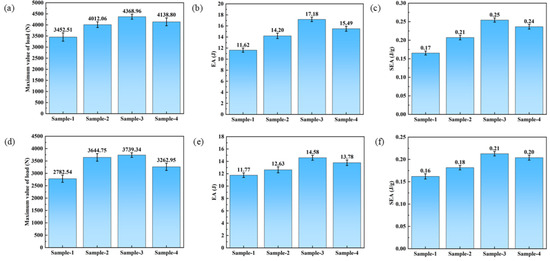
Figure 3.
The three-point bending properties of samples with different hybrid ratios: (a) load–displacement curve along the L direction; (b) comparison of EA along the L direction; (c) comparison of SEA along the L direction; (d) load–displacement curve along the W direction; (e) comparison of EA along the W direction; (f) comparison of SEA along the W direction.
3.2. Low-Velocity Impact Properties
Figure 4 shows the low-velocity impact performance of samples with different mixing ratios. In the initial stage of impact, due to the load transferred by the punch to the specimen, the impact surface produces compressive deformation, and the specimen stiffness is redistributed [35]. During this stage, the specimen transitions from the undamaged state to the damaged state, which manifests as a sudden drop of load in the load–time diagram of impact. The brittle carbon fibers in the core layer begin to fracture and small cracks begin to appear simultaneously, as the impactor continues to move downwards, resulting in oscillation in the process, as shown in Figure 4a. Taking sample S-3 as an example, once the punch contacts the sample, the impact process initiates Phase I loading as the penetration depth increases. When the impact load reaches the extreme value, the impact enters the second stage, and the curve oscillation intensifies. Plastic failure such as reinforcement fiber fracture, extraction, pits, and delamination occurred in the composite, resulting in load decrease. The impact of the punch continues, and the impact enters Stage III. The load rapidly drops, and the impact process of the sample ends, as shown in Figure 4b.
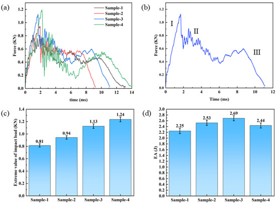
Figure 4.
The low-velocity impact properties of samples with different hybrid ratios: (a) force–time curve; (b) impact process curve; (c) comparison of peak load; (d) comparison of EA.
It can be seen that the extreme value of the impact load of the sample was positively correlated with the hybrid ratio of the sample in Figure 4c. The loading capacity of the sample to the impact load was improved by inserting carbon fiber into the glass fiber preform. This reduction in strength caused significant oscillations in the load–time curve. The damage progression in the hybrid composite remains gradual owing to the toughening effect of glass fibers. The load–time curve displayed no pronounced oscillations during Stage I, with Stage III exhibiting gradual load decay devoid of significant fluctuations. Therefore, it can be seen that the sandwich hybrid composite has better impact resistance. Compared with S-1 (2.25 J), the impact energy absorption of S-2, S-3, and S-4 increased to 2.53 J (S-2), 2.69 J (S-3), and 2.44 J (S-4), respectively, by 12.44%, 19.56%, and 8.44%. The comparative evaluation of the impact performance of the sample shows that fiber mixing has a significant impact on the impact performance of the sample, and with the increase in the mixing ratio, the impact performance of the sample is significantly improved. Due to the high brittleness of carbon fiber, the impact performance of S-4 is decreased compared with that of S-3. In summary, similar to the bending properties, as the hybrid ratio increases, impact resistance increases initially but declines after a certain hybrid ratio, with a significant deterioration observed when the hybrid ratio exceeds a critical threshold.
3.3. Damage Morphology
3.3.1. Damage Morphology of Three-Point Bending
Figure 5 shows the macroscopic three-point bending damage morphologies of samples with different hybrid ratios. Damage first appeared on the compression surface under the impact point during the bending process. With the increase in load, the crack of the specimen expanded along the width direction, causing delamination and finally failure. By comparing the surface damage of samples with different hybrid ratios after bending failure, it was found that the most serious damage of S-1 occurred, with a large area of fiber buckling damage on the compression surface, matrix cracks, continuous fiber breakage on the tensile surface, obvious delamination between the panel and the core, and serious folding buckling. When carbon fiber is mixed in the glass fiber in the way of sandwich mixing, the panel can withstand greater loads and absorb more energy in the bending process, thus significantly improving the bending damage of the sample. Therefore, the damage of the sample is arranged according to the severity of S-1, S-2, S-4, and S-3. A comparative analysis of the damage patterns in samples 2, 3, and 4 reveals that the samples’ bending resistance improves with increasing hybrid ratio. However, beyond a critical threshold (>0.67), the enhancing effect of promiscuity on bending properties diminishes significantly, ultimately transitioning to detrimental impact. Therefore, it is necessary to obtain the optimal confounding ratio with the bending property as the target value, so that the wall confounding has a negative effect.
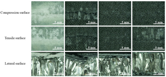
Figure 5.
The macroscopic damage morphology of samples in different hybrid ratios (from left to right: S-1, S-2, S-3, and S-4).
3.3.2. Low-Velocity Impact
Figure 6 demonstrates that composites with varying fiber hybrid ratios exhibited distinct damage morphologies on both front and back surfaces post-impact, including matrix cracking and delamination, with severity correlating to carbon/glass fiber content ratios. It can be seen that the damage decreased first and then increased with the increase in the hybrid ratio. The impacted surface exhibits a hemispherical crater morphology. Proximal to the S-1 impact locus, complete fiber fracture with cruciform failure patterns is observed, accompanied by extensive perforation zones near the punch contact area. The front panel underwent complete structural failure, with impact energy dissipation occurring through sequential absorption by the face sheet–core–back sheet sandwich configuration. Residual energy transfer induced discernible convex deformation on the rear surface. The cavity near the impact point of the punch of the impacted face of S-2 is reduced, while there is no cavity near the impact point of the punch of the impacted face of S-3. The damage of the impacted face of S-2 and S-3 is significantly improved compared with that of S-1. The damage degree of S-4 is more serious than that of S-3. Due to the greater brittleness of carbon fiber, the uniform fracture of the fibers on the impacted surface has a very obvious cross-shaped damage. The impact damage morphology of samples with different hybrid ratios can be seen. S-3 has the smallest damage degree and uniform damage surface distribution, indicating that the promiscuous ratio can better absorb the impact energy. This improvement can be attributed to the use of carbon fibers with higher mechanical strength as the surface layer. These fibers absorb significant energy and constrain impact damage to the core layer of glass fibers during the impact process. Furthermore, the glass fiber core layer plays a critical role in stress transfer and bridging after the carbon fibers fracture. Consequently, the hybrid fiber structure enhances the impact resistance of the composites.
Figure 6.
Impact damage morphology of the sample: (a) S-1 impacted surface; (b) S-2 impacted surface; (c) S-3 impacted surface; (d) S-4 impacted surface; (e) S-1 backwash surface; (f) S-2 backwash surface; (g) S-3 backwash surface; (h) S-4 backwash surface.
3.4. Fitting to Mechanical Strength
Through nonlinear regression analysis of experimental data (as shown in Figure 7), the optimal carbon/glass fiber hybrid ratio for SEA was determined. The derived constitutive equation enables mechanical property prediction of honeycomb sandwich composites based on specific hybrid ratios. The fitting equation is expressed as follows:
where y is the SEA of sample, J/g, x is the hybrid ratio, and A, B, C and D are constants.
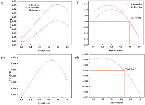
Figure 7.
Fitting of the SEA to hybrid ratio of samples and its first derivative curve: (a) Bending SEA fitting; (b) derivative of bending fitting; (c) impact SEA fitting; (d) derivative of impact fitting.
Table 4 shows the R2 values of 0.99 and 0.97 for specific energy absorption (SEA) in bending and impact processes, respectively, across specimens with different hybrid ratios. The theoretical curves demonstrate excellent agreement with experimental data, validating the constitutive equation’s predictive capability for energy absorption variation across hybrid ratios. Therefore, the fitted equation could be used to predict the variation in the energy absorption of samples with the hybrid ratio variation. First derivative analysis of the fitted curves (Figure 7b,d) yields optimal mass ratios of 0.79 and 0.68 for maximum energy absorption in bending and impact processes, respectively. The hybrid ratio obtained with the impact SEA as the target value is very close to the experimental hybrid ratio, so the optimal hybrid ratio with the impact SEA as the target value is 0.67. Samples with a 0.79 hybrid ratio were experimentally validated through bidirectional (L/W) bending tests (Table 5), confirming the constitutive equation’s accuracy. Nonlinear regression analysis established optimal hybrid ratios of 0.79 (bending) and 0.67 (impact) with experimental verification.
Table 4.
Fitting constants for SEA.
Table 5.
Comparison of SEA between samples with a hybrid ratio of 0.67 and optimum hybrid ratio.
4. Conclusions
In this study, the VARI technique was used to prepare carbon/glass sandwich hybrid composites faces with different confounding ratios, and then the carbon/glass mixed sandwich composite was prepared by bonding with AL honeycomb core, and the effects of the hybrid ratio on bending and low-velocity impact performance of the honeycomb battery housing were studied. The following conclusions were drawn:
- (1)
- The hybrid ratio of carbon/glass hybrid composite materials has a significant impact on their mechanical properties. As the hybrid ratio increases, the bending property of the material increases first and then decreases. Compared to S-1, composite samples with different hybrid ratios show an increase of 22.20–47.85% (L direction) and 7.31–23.87% (W direction) in EA and 23.53–47.06% (L direction) and 12.50–31.25% (W direction) in SEA, reaching an optimal state when the hybrid ratio was 0.67.
- (2)
- The sandwich blending of carbon fiber and glass fiber can significantly improve the impact resistance of the sample. When evaluating the overall impact of the hybrid ratio on the impact properties of the samples, it was found that the impact performance at 0.67 was the best. Compared to the results at S-1, the EA increases by 12.44%, 19.56%, and 8.44%, respectively.
- (3)
- With the increase in the mixture ratio of carbon fiber and glass fiber, the impact resistance decreases at first and then increases. This is attributed to the fact that carbon fibers with higher mechanical strength are selected as the surface layer, which provides the main mechanical strength, absorbs a lot of energy, and protects the core layer of glass fibers from impact damage during the impact process. The bottom layer of glass fibers plays a role in stress transfer and bridging after the carbon fibers break.
The current research remains at a preliminary stage, with limited application-specific testing on battery enclosures for new energy vehicles. Further electro-thermal validation experiments will be conducted in subsequent phases to address this critical aspect.
Author Contributions
Conceptualization, Y.H. and Y.Q.; methodology, Y.H.; validation, Y.L. and Y.H.; formal analysis, Y.H.; investigation, Y.Q.; resources, Y.Q.; data curation, Y.H.; writing—original draft preparation, Y.H.; writing—review and editing, Y.H.; supervision, Y.L.; project administration, Y.Q.; All authors have read and agreed to the published version of the manuscript.
Funding
This research received no external funding.
Institutional Review Board Statement
Not applicable.
Informed Consent Statement
Not applicable.
Data Availability Statement
The original contributions presented in this study are included in the article. Further inquiries can be directed to the corresponding author.
Conflicts of Interest
The authors declare no conflict of interest.
References
- Sinha, A.K.; Narang, H.K.; Bhattacharya, S. Mechanical properties of hybrid polymer composites: A review. J. Braz. Soc. Mech. Sci. Eng. 2020, 42, 431. [Google Scholar] [CrossRef]
- Das, T.K.; Ghosh, P.; Das, N.C. Preparation, development, outcomes, and application versatility of carbon fiber-based polymer composites: A review. Adv. Compos. Hybrid Mater. 2019, 2, 214–233. [Google Scholar] [CrossRef]
- Xing, Y.; Deng, B.; Qiu, T.; Cao, M.; An, Y.; Zhao, E.; Yang, S. Axial mechanical properties of welded orthogonal trapezoidal aluminum honeycomb as filler material for nuclear equipment impact limiter. Sci. Rep. 2024, 14, 27741. [Google Scholar] [CrossRef] [PubMed]
- Niu, W.; Yan, X.; He, Q.; Guo, Z. Experimental study on compression properties of composite aluminum honeycomb sandwich structures. Polym. Compos. 2024, 45, 14706–14714. [Google Scholar] [CrossRef]
- Prasad, B.; Gautam, V. Experimental and Numerical Investigations of Formability of Two-Ply Clad Sheet of Stainless Steel and Aluminium Alloy. MAPAN 2024, 39, 887–900. [Google Scholar] [CrossRef]
- Bogin, W.; Śliwa, R.E.; Ziaja, W.; Ostrowski, R. The influence of modification of the geometry of the front surface of the RFSSW tool inner sleeve on the fatigue life of joints during joining clad sheets made of aluminum alloy 2024-T3. Arch. Civ. Mech. Eng. 2024, 25, 17. [Google Scholar]
- Turlin, R.; Le Grognec, P. Analytical solutions for the buckling/wrinkling of anisotropic sandwich structures: Application to honeycomb cores. Compos. Struct. 2025, 351, 118618. [Google Scholar] [CrossRef]
- Xiang, H.; Shi, Y.; Yang, Q.; Wang, X.; He, Y. Optimization Design of Honeycomb Absorbing Structure and Its Application in Aircraft Inlet Stealth. Aerospace 2024, 11, 796. [Google Scholar] [CrossRef]
- Di Giulio, E.; Nguyen, C.T.; Gloria, A.; Perrot, C.; Dragonetti, R. Three-dimensional cellular structures for viscous and thermal energy control in acoustic and thermoacoustic applications. Int. J. Heat Mass Transf. 2024, 234, 126076. [Google Scholar] [CrossRef]
- Yuan, Y.; Liu, B.; Sha, Z.; Zhang, Z.; Wang, Z. Zero group velocity feature in CFRP-Nomex honeycomb structure and its use for debonding detection. Mech. Syst. Signal Proc. 2024, 216, 111479. [Google Scholar] [CrossRef]
- Fang, G.; Zhou, H.; Meng, A.; Tian, L. How to crack the impossible triangle of new energy coupled system—Evidence from China. Appl. Energy 2024, 374, 124065. [Google Scholar] [CrossRef]
- Jun, D.; Dongran, L.; Xihao, D.; Bo, L.; Shiyao, L.; Yuzheng, J.; Tongtao, M. Key Issues and Technical Applications in the Study of Power Markets as the System Adapts to the New Power System in China. Sustainability 2021, 13, 13409. [Google Scholar] [CrossRef]
- Jiang, W.; Du, L.; Wei, H.; Sun, H. The influence of urban new energy development orientation on new energy technology innovation in firms. Renew. Energy 2024, 237, 121873. [Google Scholar] [CrossRef]
- Xie, Y.; Xu, X.; Liu, S. Machine vision-based detection of surface defects in cylindrical battery cases. J. Energy Storage 2024, 101, 113949. [Google Scholar] [CrossRef]
- Zhao, Y.; Zheng, S.; Yan, M.; Liu, X.; Wang, B.; Shi, J.; Yin, J.; Ma, F. Experimental analysis on mechanical properties of BF/PLA composites and its lightweight design on power battery box. Proc. Inst. Mech. Eng. Part D J. Automob. Eng. 2022, 236, 2894–2913. [Google Scholar] [CrossRef]
- Toldy, A.; Szolnoki, B.; Marosi, G. Flame retardancy of fibre-reinforced epoxy resin composites for aerospace applications. Polym. Degrad. Stabil. 2011, 96, 371–376. [Google Scholar] [CrossRef]
- Wang, B.; Fang, X.; Xue, Y. Study on aramid short fiber reinforced CFRP/aluminum layered structure and its galvanic corrosion resistance. J. Adhes. Sci. Technol. 2023, 37, 469–485. [Google Scholar] [CrossRef]
- Mao, Y.; Dong, G.; Fu, Y.; Li, Y.; Huang, P.; Fu, S. High performance shape-adjustable structural lithium-ion battery based on hybrid fiber reinforced epoxy composite. Compos. Struct. 2023, 325, 117598. [Google Scholar] [CrossRef]
- Mudassir, M.; Tarlochan, F.; Mansour, M.A. Nature-Inspired Cellular Structure Design for Electric Vehicle Battery Compartment: Application to Crashworthiness. Appl. Sci. 2020, 10, 4532. [Google Scholar] [CrossRef]
- Zhao, Y.; Shi, J.; Wang, K.; Wang, B.; He, C.; Deng, X. Mechanical Properties and Optimization Analysis on Battery Box with Honeycomb Sandwich Composite Structure. Int. J. Automot. Technol. 2023, 24, 1–14. [Google Scholar] [CrossRef]
- Feng, G.; Xiao, C.; Wang, H.; Zhang, H.; Liu, B.; Wang, C. Enhancing mechanical properties of 3D-printed continuous carbon fibre-reinforced composites via bio-inspired design. Thin-Walled Struct. 2025, 207, 112737. [Google Scholar] [CrossRef]
- Zhu, W.; Wang, N.; Zhi, Q.; Zhang, Z.; Fu, L.; Zhang, Y.; Li, D. Highly protective and functional strengthening strategies for 3D printed continuous carbon fiber reinforced polymer composites: Manufacturing and properties. Compos. Commun. 2024, 52, 102145. [Google Scholar] [CrossRef]
- Zhu, X.; Deng, J.; Heidari, A.; Jamei, M.; Alizadeh, A. Mechanical performance evaluation of optimal hybrid composite fabricated with glass and carbon fibers and thermoplastic polypropylene matrix or fencing sports athletes. Int. Commun. Heat Mass Transf. 2025, 160, 108346. [Google Scholar] [CrossRef]
- Niranjan, C.A.; Kar, S.; Srinivas, S.; Jain, V.K.S.; Siddaraju, C. Effect of Al2O3 and ZrO2 nanoparticles on microstructure and mechanical properties of Mg-AZ91 hybrid nanocomposites. Mater. Today Commun. 2024, 41, 110988. [Google Scholar]
- Mashhadzadeh, A.H.; Mashhadzadeh, A.H.; Golman, B.; Spitas, C.; Faroughi, S.A.; Kostas, K.V. Recent advancements in mechanical properties of graphene-enhanced polymer nanocomposites: Progress, challenges, and pathways forward. J. Mol. Graph. Model. 2025, 135, 108908. [Google Scholar] [CrossRef]
- Li, M.; Zhang, P.; Cui, J.; Liu, Z.; Zhao, Y.; Qiu, Y.; Li, H. Effect of hybridization on free vibration response of Carbon/Glass hybrid composite laminates. J. Reinf. Plast. Compos. 2024, 43, 818–830. [Google Scholar] [CrossRef]
- Ikbal, H.; Wang, Q.; Azzam, A.; Li, W. Effect of hybrid ratio and laminate geometry on compressive properties of carbon/glass hybrid composites. Fiber. Polym. 2016, 17, 117–129. [Google Scholar] [CrossRef]
- Shi, L.; Yang, H.; Wu, Z.; Peng, L.; Ni, Q.; Li, Q. Effect of fiber layout on low-velocity impact response of intralaminar hybrid carbon/glass fiber braided composite pipes under internal pressure. Thin-Walled Struct. 2024, 198, 111711. [Google Scholar] [CrossRef]
- Hu, J.; Ma, J.; Jin, K.; Huang, Y.; Zhang, X.; Zheng, X.; Lu, W.; Zhao, J.; Chen, D. Pseudo-ductility behavior of carbon/glass hybrid composites with unidirectionally arrayed chopped strands: Experimental and numerical research. Polym. Compos. 2024, 45, 14741–14756. [Google Scholar] [CrossRef]
- Thi, H.N. Transient Response of Auxetic Honeycomb Sandwich Shell Integrated with Laminated Three-Phase Polymer/GNP/Fiber Face Sheets Subjected to Low-Velocity Impact Load. J. Vib. Eng. Technol. 2025, 13, 71. [Google Scholar] [CrossRef]
- King, W.T.; Guin, W.E.; Jordon, J.B.; Barkey, M.E.; Allison, P.G. Effects of honeycomb core damage on the performance of composite sandwich structures. J. Compos. Mater. 2020, 54, 2159–2171. [Google Scholar] [CrossRef]
- Zhang, L.; Che, Z.; Zhu, Y.; Hou, P.; Liu, Z.; Wang, Y.; Wang, J.; Zhang, T.; Hong, Y. Preparation and mechanical properties of the 2.5D carbon glass hybrid woven composite materials. Sci. Eng. Compos. Mater. 2024, 31, 20240026. [Google Scholar] [CrossRef]
- ASTM C393/C393M-20; Standard Test Method for Core Shear Properties of Sandwich Constructions by Beam Flexure. ASTM International: West Conshohocken, PA, USA, 2020.
- ASTM D7136/D7136M-20; Standard Test Method for Measuring the Damage Resistance of a Fiber-Reinforced Polymer Matrix Composite to a Drop-Weight Impact Event. ASTM International: West Conshohocken, PA, USA, 2020.
- Yao, H.; Hui, W.J.; Yunzhong, L.; Jiamin, N. Impact protection enhancement by negative mass meta-honeycombs with local resonance plates. Compos. Struct. 2023, 321, 117330. [Google Scholar]
Disclaimer/Publisher’s Note: The statements, opinions and data contained in all publications are solely those of the individual author(s) and contributor(s) and not of MDPI and/or the editor(s). MDPI and/or the editor(s) disclaim responsibility for any injury to people or property resulting from any ideas, methods, instructions or products referred to in the content. |
© 2025 by the authors. Licensee MDPI, Basel, Switzerland. This article is an open access article distributed under the terms and conditions of the Creative Commons Attribution (CC BY) license (https://creativecommons.org/licenses/by/4.0/).