1. Introduction
The demand for spaceborne GNSS (Global Navigation Satellite System) real-time orbit determination technology is growing steadily in fields such as spacecraft orbit control, precise positioning, and flight monitoring. As satellite science and technology advance, the accuracy requirements for spaceborne GNSS orbit determination are becoming increasingly stringent. A technical framework based on post-mission precise orbit determination (POD) and real-time precise orbit determination (RTOD) has been developed [
1].
In recent years, post-mission precise orbit determination (POD) has advanced significantly, with orbit determination accuracy reaching centimeters. In 1982, LANDSAT-4 became the first resource satellite with a GNSS receiver, as well as the first LEO satellite to successfully use GNSS-based orbit determination. Although its accuracy was limited to several tens of meters, it was a significant advancement in the field [
2]. In 1992, the TOPEX/Poseidon satellite, developed in collaboration between the United States and France, carried a GPS receiver and achieved the first centimeter-level orbit determination using post-processed ground techniques, demonstrating the potential for high-precision satellite positioning [
3]. Germany’s GFZ launched the CHAMP satellite in 2000, which was equipped with NASA’s Jet Propulsion Laboratory’s (JPL) Black Jack GPS receiver. Ijssel et al. (2003) used a reduced-dynamic orbit determination technique using ionosphere-free phase combinations to show that CHAMP’s 3D orbit accuracy approached sub-decimeter levels [
4]. Zhao Qile et al. (2005) achieved centimeter-level orbit precision with the CHAMP and GRACE satellites [
5]. Yang Yuanxi et al. (2013) improved the study of relative orbit determination for GPS satellite formations, achieving an accuracy of 5 mm [
6]. Guo Xiang et al. (2013) confirmed the HY-2A orbit determination results using Satellite Laser Ranging (SLR), obtaining an accuracy of 1–2 cm [
7]. Zhou Xuhua et al. (2015) used a reduced-dynamic method and obtained a mean radial accuracy of 1.3 cm and a 3D accuracy of 6.2 cm [
8]. Xu Na (2019) combined geometric and dynamic approaches to achieve centimeter-level precision [
9]. Jiang Kecai (2020) determined a long-arc orbit for the high-altitude satellite TJS-2. The non-differenced overlapping orbit approach had a precision of 1.3 m, but the epoch-differenced method successfully reduced slowly varying geometric errors, increasing orbit determination accuracy to more than 0.7 m [
10].
With the rapid advancement of space technology, real-time orbit determination research evolved in response to the growing demand for autonomous satellite navigation, notably the independent functioning of low Earth orbit (LEO) satellites. This field has made steady international advancement. For example, Goldstein et al. (2001) at NASA’s Goddard Space Flight Center used dual-frequency GPS pseudorange measurements from the TOPEX/Poseidon satellite to obtain meter-level real-time orbit accuracy [
11]. Reichert et al. (2022) at JPL obtained an accuracy of about 1.5 m using onboard dual-frequency GPS data from the SAC-C satellite [
12]. Montenbruck et al. (2008) developed a method for absorbing mistakes from broadcast ephemerides by modeling carrier phase ambiguities as random-walk parameters, resulting in a real-time accuracy of 0.5 m [
13]. More recently, Montenbruck et al. (2022a) used onboard GPS and Galileo observations from the Sentinel-6A satellite to achieve a real-time orbit determination accuracy of 0.1 m, outperforming other satellites with onboard GNSS real-time orbit determination capabilities [
14].
In recent years, the development of multi-frequency, multi-constellation GNSS systems (such as GPS and BDS) has accelerated research into real-time orbit determination utilizing spaceborne GNSS data. Several research groups have made significant progress, particularly in the integration of multi-source observations, model refining, and filtering strategy optimization. With the implementation of dual-system fusion, real-time orbit determination precision has progressively increased, from meter-level in the early 2000s to centimeter- and even sub-centimeter-level beyond 2020. This tendency represents the ongoing technological improvement and maturation of real-time orbit determination, bringing it closer to the international standard. Wang Fuhong et al. (2006) used the CHAMP spacecraft to achieve an onboard GPS real-time orbit determination accuracy of 1.5–3 m [
15]. Wang et al. (2015) presented a “pseudo-ambiguity” methodology to absorb broadcast ephemeris errors, achieving an accuracy of 0.39 m utilizing dual-mode (GPS+BDS) observations from the FY3C satellite [
16]. Li et al. (2022) achieved a 0.2 m precision using BDS-3 B1C/B2a readings from the HY2D satellite [
17]. Zhang Wanwei et al. (2024) used a numerical stepwise search and comparison method to optimize the random process parameters for pseudo-ambiguities. Using two low-Earth orbit satellites, GRACE-C and SWARM-A, they achieved a real-time exact orbit determination 3D position error (RMS) of around 4.62 to 7.56 cm [
18]. Zheng Yongai et al. [
19] used ultra-rapid forecast ephemerides from the ground-based IGS (International GNSS Service) to replace broadcast ephemerides and performed real-time orbit determination of LEO satellite positions and velocities. Compared to traditional airborne orbit determination methods, the sub-meter precision method suggested in this study has substantial advantages, especially in real-time orbit determination in high-dynamic settings. While other investigations, like Sentinel-3A, have demonstrated good orbit accuracy, traditional and novel approaches may perform similarly in some circumstances [
20,
21,
22]. Wang Fuhong et al. [
23] improved real-time orbit determination accuracy by reasonably setting the random model of pseudo-ambiguity parameters, achieving a roughly 10% improvement over GPS. However, the introduction of additional parameters during the numerical integration phase increased the computational load, which may make this algorithm unsuitable for spaceborne GNSS receivers.
The research on sub-meter-level orbit determination discussed above has only been validated in ground-based tests and has yet to be verified on spaceborne GNSS receiver platforms. In existing gravity field models, the degree of expansion at different orders significantly impacts orbit determination accuracy. However, as the order increases, the computational load required grows exponentially [
24,
25,
26]. To match the computational capabilities of spaceborne receivers, it is essential to strike the right balance between computational efficiency and orbit determination accuracy. By selecting an appropriate gravity field model order, accuracy can be ensured while minimizing the consumption of system resources as much as possible. Therefore, optimizing orbit determination accuracy under limited system resources has become a critical challenge that needs to be addressed.
2. Materials and Methods
The current mainstream spaceborne receiver products rely on GPS/COMPASS dual-frequency observation data to establish pseudo-ambiguities of carrier phase observations, the parameters to be estimated, and their corresponding random models, which are used to compensate for errors in broadcast ephemerides. These error parameters can absorb the propagation path delay of broadcast ephemerides due to their inherent slow-varying characteristics and the constraints imposed by the dynamic model. However, if the dynamic model loses its constraining effect, the error parameters will no longer be able to absorb the propagation path delay of the broadcast ephemerides. The accuracy of the dynamic model is primarily determined by the gravity field model [
27,
28].
2.1. Satellite Observation Equation
In spaceborne GNSS receiver orbit determination, pseudorange and carrier phase are the most important observables for locating (Lou et al., 2022) [
29]. After thoroughly evaluating all sources of inaccuracy, the observation models for pseudorange and carrier phase may be developed. The pseudorange observation equation is shown in Equation (1).
In this equation,
represents the pseudorange observation value, where the superscript “
s” refers to GPS satellites, the subscript “
” indicates the
and
frequencies (with
i = 1 for
), and the subscript “
Leo” denotes the spaceborne GNSS receiver.
represents the geometric distance between the LEO satellite’s GNSS receiver and the GPS satellite.
is the speed of light in a vacuum,
represents the clock bias,
represents the ionospheric delay,
represents the tropospheric delay,
represents hardware delay, and
represents the observation phase noise. The carrier phase observation model is:
In this equation, represents the carrier phase observation value, represents the GPS signal wavelength, and represents the integer cycle carrier phase ambiguity. The meanings of the other symbols are the same as those defined above.
Two main categories can be used to describe the forces operating on an artificial satellite while it is in orbit around the Earth:
- (1)
Conservative forces: These include the gravitational pull from third bodies like the Sun and Moon, the perturbations from the Earth’s non-spherical gravity field because of its ellipsoidal shape and heterogeneous mass distribution, and the central gravitational field produced by the Earth’s mass center—assuming that the Earth’s mass is concentrated at a point at the geocenter. These forces are the main and most important elements in orbit determination models, and they are distinguished by well-defined potential functions.
- (2)
Non-conservative forces: These include atmospheric drag caused by interactions with rarefied atmospheric particles at orbital altitudes, solar radiation pressure acting on the satellite’s surface, recoil forces caused by the satellite’s thermal emissions, interactions with the geomagnetic field, tidal effects, and other non-conservative disturbances. Accurate modeling of these forces necessitates precise information about the satellite’s surface material qualities, geometric configuration, real-time attitude data, and surrounding environmental variables.
The combined impact of the aforementioned conservative and nonconservative forces regulates the satellite’s orbital dynamics [
30]. The solution strategy is presented in
Table 1 below [
31,
32,
33,
34,
35]:
2.2. Error Model Analysis
LEO satellites operate at relatively low altitudes in a complicated orbital environment characterized by multiple perturbative factors, many of which are challenging to accurately model. While the majority of these pressures can be adequately compensated using existing models, certain non-conservative perturbations remain difficult to precisely quantify and require further investigation to improve overall orbit determination accuracy [
36]. Montenbruck et al. completed a thorough examination of the perturbative forces operating on an LEO spacecraft at 500–1000 km altitude. The typical magnitudes of these forces are summarized in
Table 2 [
37].
Effect of Atmospheric Density Models on Orbit Determination Accuracy
Atmospheric drag perturbation refers to the aerodynamic resistance exerted by the atmosphere on a satellite and is one of the most common perturbation sources for LEO satellites [
38,
39,
40]. This can be expressed as:
In this context, and represent the atmospheric drag perturbations on the satellite body and the solar panels, respectively.
can be expressed as:
In this equation, denotes the area-to-mass ratio of the satellite, defined as the ratio of its reference cross-sectional area to its mass, denotes atmospheric density, and represents the velocity of atmospheric motion.
Satellites use varying installation angles for their solar panels and sun-pointing control systems. As a result, the direction and amount of air drag vary correspondingly. This section describes the method for calculating the atmospheric drag acceleration acting on solar panels in a full sun-pointing control mode, where the panels are constantly pointed toward the Sun. In this design, the atmospheric drag acceleration on the solar panels
is given by:
In this equation, represents the solar panel’s air drag coefficient, is the panel area, and is the unit normal vector of the surface. The atmospheric drag coefficient is difficult to properly calculate due to factors such as satellite surface material, shape, and atmospheric composition. Furthermore, the satellite’s cross-sectional size is not constant; when the attitude changes, the projected area perpendicular to the velocity vector fluctuates over time. As a result, in orbit determination, the product is often handled as an unknown quantity to be estimated with the satellite’s state variables.
The present atmospheric density models are primarily dependent on years of observational data, and each model has a limited range of applications. In this part, the DTM-94 atmospheric density model, the initial set of six orbital elements, the EIGEN-6C gravity field model, Earth Orientation Parameters (EOP), and other necessary inputs are utilized to simulate the satellite’s orbital state under actual operational conditions. This orbit is used as a reference trajectory to assess the performance of different atmospheric density models. The orbit is then determined using the DTM-78, MSISE-90, and NRLMSISE-00 models, and the results are compared. The results are presented in
Table 3.
In addition to atmospheric density, the solar panel area has an impact on atmospheric drag during satellite operation. Satellites in LEO occasionally travel into the Earth’s shadow. The software determines the solar panel’s effective area based on satellite, Earth, and Sun locations. This section uses the DTM-94 atmospheric model to simulate an orbit with a solar panel area of 2 m
2 as the reference value. To evaluate the impact of panel area variation on orbit determination findings, we performed a comparative accuracy investigation using area parameters of 4 m
2 and 6 m
2. The results are presented in
Table 4.
The results indicate that the orbit determination accuracy achieved from various atmospheric density models is relatively similar. This is due to two main reasons: first, the differences between these models are relatively small for LEO satellites; second, while there are differences between the models, the addition of atmospheric drag parameters and empirical force model parameters for radial, tangential, and normal directions allows these empirical parameters to account for the majority of the unmodeled atmospheric drag. As a result, the accurate orbit determination results are remarkably consistent. This study focuses specifically on the effect of solar panel area variation on orbit determination accuracy. The simulation results reveal that changes in panel area can dramatically increase atmospheric drag, resulting in orbit inaccuracies of up to a meter—far beyond the discrepancies reported across various atmospheric density models. These findings highlight the vital relevance of precisely modeling solar panel properties in orbit determination, and they also validate the effectiveness of empirical force parameters in adjusting for unmodeled disturbances.
2.3. Satellite Motion Equations
According to Newton’s law of universal gravitation, two objects exert a gravitational force on each other, with the magnitude of the force being directly proportional to the product of their masses and inversely proportional to the square of the distance between them. For satellites, the Earth’s gravitational force is the dominant central force. However, to fully describe the satellite’s motion, other forces must also be considered. While these additional forces are relatively small, they cannot be neglected in precise orbit calculations. The satellite’s motion is primarily governed by the Earth’s central gravitational force, and the satellite’s motion equation is [
41]:
In this expression,
represents the satellite’s position vector in the inertial reference frame;
is the total perturbing acceleration acting on the satellite, including both conservative and non-conservative forces. These forces include, for example, the Earth’s non-spherical gravitational field, atmospheric drag, solid tides, and ocean tides. To simplify numerical computation, this can be converted into a system of first-order differential equations:
In this equation, V stands for the satellite’s velocity vector. Given the initial state vector at time and the forces acting on the satellite, the state vector at the next time , can be determined through numerical integration. As a result, the numerical solution to the satellite’s motion equation becomes an initial value problem for an ordinary differential equation.
2.4. Non-Spherical Earth Gravitational Perturbation
The gravitational field of the Earth plays a significant role in satellite orbit determination. Accurately detecting the satellite’s acceleration within the Earth’s gravitational field is crucial for improving orbit determination precision. The spherical harmonic expansion of the gravitational field is an effective method for representing the Earth’s gravitational potential and hence for calculating the satellite’s acceleration. The spherical harmonic expansion of gravitational potential V is shown below [
15].
is the distance from the Earth’s center; is the geocentric latitude; is the geocentric longitude; is the Earth’s standard gravitational coefficient; is the reference radius (usually the Earth’s average radius); and are the spherical harmonic coefficients, corresponding to the cosine and sine components, respectively. represents the symmetric part of the Earth’s mass distribution, while represents the asymmetric part; is the normalized associated Legendre polynomial. Using the spherical harmonic expansion of the gravitational potential , the gravitational acceleration acting on the satellite can be obtained by computing the gradient of the gravitational potential: . By substituting the spherical harmonic-expanded gravitational potential into this equation, the radial, tangential, and normal components of the gravitational acceleration in three-dimensional space can be computed from the gradient of the potential.
Radial acceleration
:
Tangential acceleration
:
Normal acceleration
:
By combining these components, the satellite’s total acceleration at any given position can be determined.
2.5. Numerical Integration
The satellite motion equation is an extremely complex differential equation due to the multiple changing variables. Although an analytical solution is theoretically conceivable, the process is extremely complex and time-consuming, and some perturbing factors are challenging to represent and solve. As a result, analytical methodologies are inadequate for practical engineering applications. Thus, numerical integration is employed to solve the motion equation. Numerical integration enables a full estimation of the parameters involved in orbit determination, with the resulting accuracy meeting engineering standards.
This paper employs the Runge–Kutta–Fehlberg single-step integration method to integrate the orbit and state transition matrix. The classical Runge–Kutta method approximates the derivative of the function
by a linear combination of the right-hand function values at several points within the integration interval [
,
]. The coefficients of this approximation are then determined using a Taylor expansion, which allows for avoiding the calculation of higher-order derivatives while maintaining accuracy. If F(k) represents the highest order achieved by calculating the function
k times, then F(k) = k, where
, and F(5) = 4, F(6) = 5, F(7) = 6, and so on. The classical Runge–Kutta method has a fixed integration step size, complicating the treatment of local truncation errors. In contrast, the Runge–Kutta–Fehlberg technique enables dynamic adjustment of the step size by supplying two sets of Runge–Kutta formulas: one of order m and one of order m + 1. The local truncation error can be calculated using both formulas, which will help determine the size of the next integration step. The related RKF4(5) formula is given below:
The values of the coefficients
can be found in detail in reference [
42].
2.6. Real-Time Filtering Method
A significant problem in real-time orbit determination for low Earth orbit (LEO) satellites is choosing appropriate estimation parameters and methodologies depending on the underlying dynamical and observational models. This work uses a simplified dynamic orbit determination approach for real-time applications. The method combines the dynamical model with geometric GNSS observations to enable the estimate of model parameters and empirical accelerations using observation data. These empirical accelerations help to correct flaws in the dynamic model. In situations where GNSS readings are interrupted or deteriorated in quality, orbit propagation via numerical integration can continue to deliver orbital forecasts, maintaining excellent stability. As a result, the reduced dynamic technique is naturally less sensitive to both model and observational mistakes. This technique builds on the satellite. This approach extends the previously introduced satellite dynamical equations and the GNSS observation model given in
Section 2.1. The state vector
, reflecting the estimated parameters in onboard GNSS real-time orbit determination, can be expressed as follows:
In this expression,
and
are the position and velocity of the satellite’s center of mass;
and
are the scale factors for solar radiation pressure and air drag, respectively;
and
are the empirical accelerations in the along-track and cross-track directions within the orbital frame;
are the ambiguity parameters of the ionosphere-free (IF) combined carrier phase measurements; and m is the number of GNSS satellites involved in the solution. Using the defined set of estimated parameters, the carrier phase observation equation in Equation (1) is enlarged using a first-order Taylor series approximation, yielding the linearized observation equation:
In the equation,
represents the epoch;
and
denote the residuals between the observed and computed pseudorange and carrier phase measurements, respectively;
is the observation noise;
and
are the linearized observation matrices for pseudorange and carrier phase, respectively; and
denotes the initial state vector. Incorporating the dynamical model, the functional model of the filter can be expressed as:
In the equation, and denote the process noise.
In real-time data processing, filtering is commonly used to estimate parameters. For the functional model mentioned above, we use the Square Root Information Filter (SRIF) as an estimator. The JPL created SRIF, an improved form of the Kalman filter, which provides greater computing efficiency and numerical stability. Householder transformations are used during the filtering process, which is an important component of SRIF (Bierman, 1977) [
43]. The real-time orbit determination process based on SRIF is described in
Figure 1.
3. Results
3.1. Data Source
The Gaofen-7 satellite is a high-resolution Earth observation satellite that operates in a sun-synchronous orbit at an altitude of about 506 km. The observation data used in this study are spaceborne GPS dual-frequency data with a 1 s sampling interval, and the observation arc lasts for 24 h. The reference orbit is based on post-mission precise orbit data provided by Wuhan University. This study compares and analyzes the orbit determination accuracy of the same gravity field model at different orders using on-orbit data from the Gaofen-7 satellite collected between 20 March 2022, and 28 April 2022. The Gaofen-7 satellite has a repeat cycle of about 60 days. Although only 40 days of on-orbit observation data have been acquired thus far, this timeframe adequately captures the fundamental aspects of the orbital cycle, ensuring strong representativeness. It accurately depicts the satellite’s operating behavior and orbit determination accuracy throughout this stage of its orbit.
3.2. Data Preprocessing
Data preprocessing is used to identify excessive mistakes and cycle lapses in GNSS measurements. The Geometry-Free (GF) [
44] and Melbourne–Wübbena (MW) [
45] combinations are popular methods for detecting cycle slip, and they are frequently employed jointly. Blewitt (1990) [
46] proposed the TurboEdit approach, which detects gross errors and cycle slippage using dual-frequency GF and MW combinations. Its usefulness in GNSS-based positioning and orbit determination has been well tested (Li Min 2011) [
41]. As a result, this work uses the TurboEdit approach to preprocess dual-frequency GNSS data and then finds gross mistakes using dual-frequency pseudorange observations.
Figure 2 depicts the whole data preprocessing method.
3.3. Components of the GNSS System
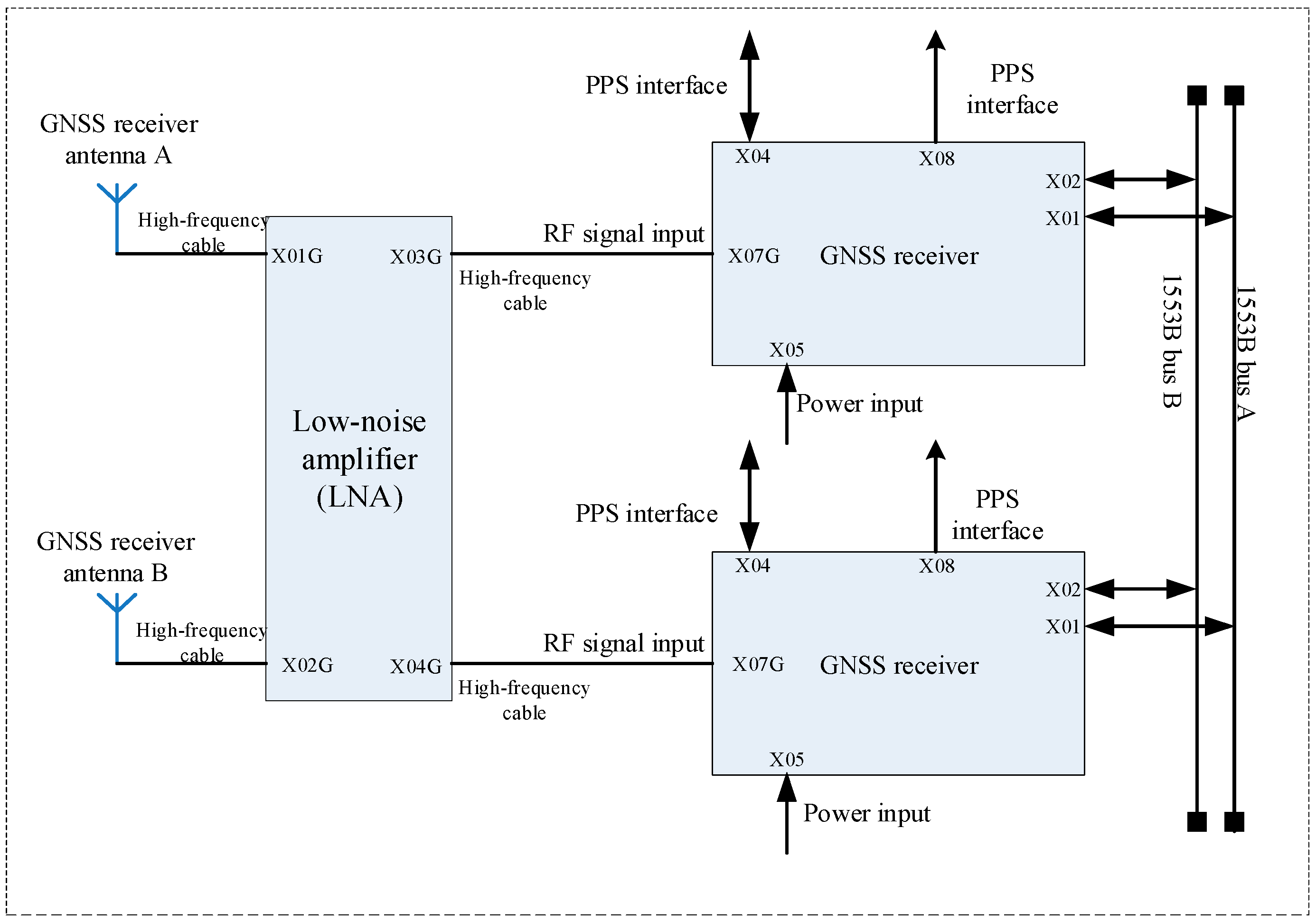
The onboard GNSS receiver system consists of two GNSS receiving antennas, one low-noise front-end amplifier, and two GNSS navigation receivers. The GNSS antennae collect navigation signals, which are first filtered and boosted by the front-end amplifier before being routed to the navigation receivers. These receivers perform signal processing functions like down-conversion, digital sampling, demodulation, despreading, acquisition, and tracking in order to obtain raw navigation observation data. These data allow the satellite to execute key activities such as positioning, orbit determination, and timing. The GNSS system architecture is illustrated in
Figure 3.
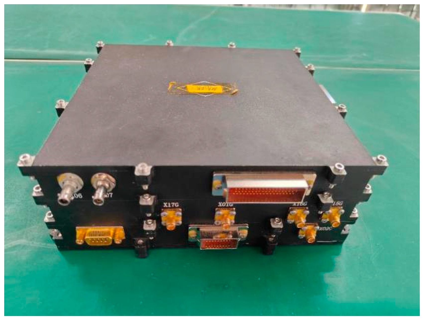
The Gaofen-7 satellite’s onboard receiver has an FT601 floating-point DSP processor with a 32-bit external bus and word-access mode. With a clock speed of 160 MHz, the CPU can achieve up to 960 MFLOPS in floating-point operations and 1280 MIPS in fixed-point performance. The device features two multichannel buffered serial ports (MCBSP), 1 Mbit of on-chip SRAM, and two 32-bit timers. The processor’s EMIF interface allows for connectivity with a variety of external memory types, including SBSRAM, SDRAM, and asynchronous memory. In this investigation, the DSP operates at a frequency of 112 MHz. The BOOTMODE pin is set to allow MAPI memory mapping, and the system initializes programs using a 16-bit FLASH loading method. Several critical operations in spaceborne GNSS receivers must be done in under a second, including inter-board communication, data packaging, and clock disciplining. Among these jobs, the sub-meter-level orbit determination technique normally requires a large amount of computer power.
Figure 4 provides an overview of the Gaofen-7 receiver system architecture, while
Figure 5 outlines the software execution flow of the orbit determination module.
3.4. Analysis of Orbit Determination Accuracy for Different Orders
The accuracy evaluation in this study starts 60 min after the orbit determination starts in order to account for the filter’s notable convergence characteristic during the initial phase. This method removes the impact of initial state mistakes on the accuracy evaluation and guarantees that the results represent the filter’s stable performance. Using the EIGEN6C model as an example, when the gravity field order is 50, the radial, tangential, and normal position accuracies are 0.523 m, 0.233 m, and 0.290 m, respectively, with a three-dimensional position accuracy of 0.654 m. When the order is increased to 60, the radial, tangential, and normal position accuracies improve to 0.420 m, 0.191 m, and 0.225 m, respectively, with a three-dimensional position accuracy of 0.522 m. The radial, tangential, and normal accuracy improves by around 0.01 m, 0.004 m, 0.007 m, respectively, while the three-dimensional position accuracy improves by about 0.013 m. The accuracy of orbit determination increased by over 20% overall. Further study demonstrates that, while orbit determination accuracy improves with increasing gravity field model degree, the rate of progress gradually slows. Given the trade-off between accuracy increases and computational expense, a degree of 60 is suggested as the ideal choice. This strikes a sensible compromise between orbit precision and resource consumption, providing an effective and feasible optimization technique for onboard processing systems. The next stage is to determine whether the receiver can handle the system resources required by changes in the gravity field order.
Figure 6 and
Table 5 below show the specific results for orbit determination accuracy at different orders.
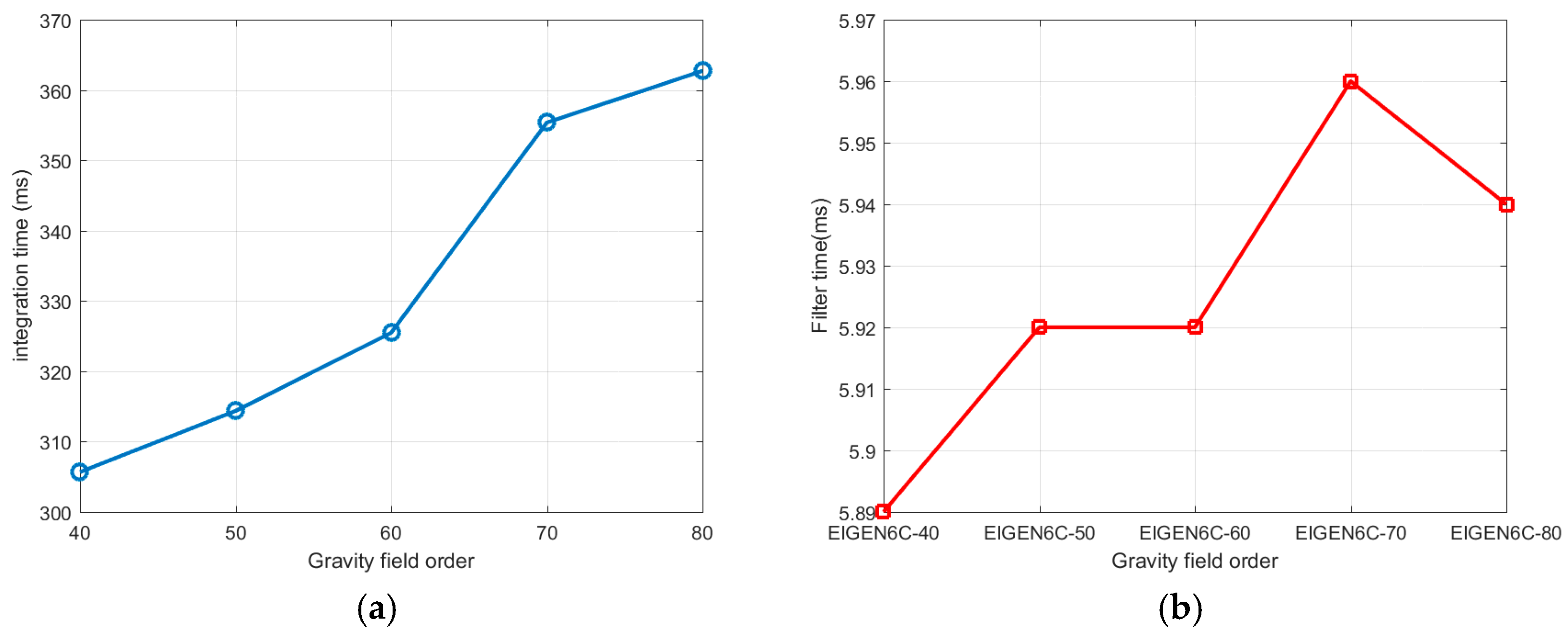
3.5. Comparison of CPU Resources for Different Orders
This section investigates the computing efficiency of models at different orders. Higher-order gravity field models produce more precise orbit determination results, but they also add significant computing complexity. This is especially true for spaceborne GNSS receivers with limited CPU power, where computational efficiency is important. Thus, in addition to comparing accuracy, it is critical to assess the computational efficiency of various gravity field models. To accomplish this, this section examines the computation times of various order models for processing identical data.
3.5.1. Verification of CPU Resources on PC
The current study looks at two important computing phases linked to gravity field order: numerical integration and filtering. The goal of comparison analysis is to discover the optimal balance of accuracy and efficiency, giving theoretical support for enhancing the orbit determination performance of spaceborne GNSS receivers. The validation results for the personal computer (PC) are shown in
Figure 7 and
Table 6:
The receiver currently features a built-in gravity field model of order 50. After testing on a personal computer (PC), it was discovered that increasing the order from 40 to 60 resulted in a significant improvement in accuracy while incurring no notable increase in computing time. As a result, raising the gravitational field order is a realistic strategy. The next step is to move the code to the spaceborne GNSS receiver and ensure that it works properly.
3.5.2. Verification of CPU Resources in the Receiver
To verify that the receiver can satisfy all task time restrictions while performing high-precision orbit determination, a complete examination of the orbit determination algorithm’s computation time under various gravity field models is required [
47,
48]. By measuring the calculation time for each model order, we can ensure that all receiver duties work properly, ensuring the system’s overall stability. Next, we evaluate the performance of each order model on the spaceborne receiver and investigate how to strike the best balance between orbit determination accuracy and computational efficiency with limited computational resources. Verification results from the receiver are shown in
Figure 8 and
Table 7:
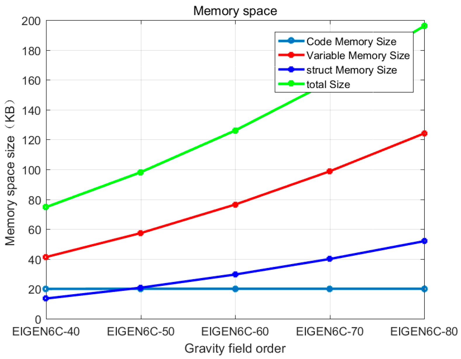
3.6. Memory Resource Analysis
On spaceborne GNSS receivers, memory resources are constrained, and gravity field models with excessively high orders may result in memory overflow. As a result, optimizing memory use while preserving orbit determination accuracy has become a significant topic that demands in-depth investigation. The structure of the gravity field in the programming implementation is depicted in
Table 8:
The gravitational mass coefficient of the celestial body is approximately 3,986,004,415
, and the Earth’s reference radius is about 6,378,136.46 m. The order and degree of the spherical harmonic coefficients are the main subjects of this investigation. In this comparison, KB (kilobytes) is used as the unit of measurement to examine the memory space occupied by different orders, with a particular focus on the space occupied by the code (.text), static variables and global variables (.bss), and the memory used by the gravity field definition structures. The memory usage for different orders is shown in
Table 9 and
Figure 9.
The experimental results reveal that when the order grows from 40 to 80, the memory space required by static variables, global variables, and structures gradually increases, as does the memory demand throughout the computation process. Comparing memory consumption at different orders reveals that the existing system’s memory allocation is sufficient to enable gravity field model calculations up to order 80, although this is approaching the memory limit. To allow calculations at even higher levels, memory allocation must be further optimized or system memory resources increased to ensure that the calculations run smoothly. This analysis gives critical information for carrying out high-order gravity field model calculations in resource-constrained contexts.


