
Microstructure of Mortar with Ballast Waste as a Cement Replacement


Abstract
1. Introduction
2. Materials and Methods
2.1. Materials
2.2. Methods
3. Results and Discussion
3.1. Initial Samples
3.1.1. Mineralogical Composition
3.1.2. Chemical Composition
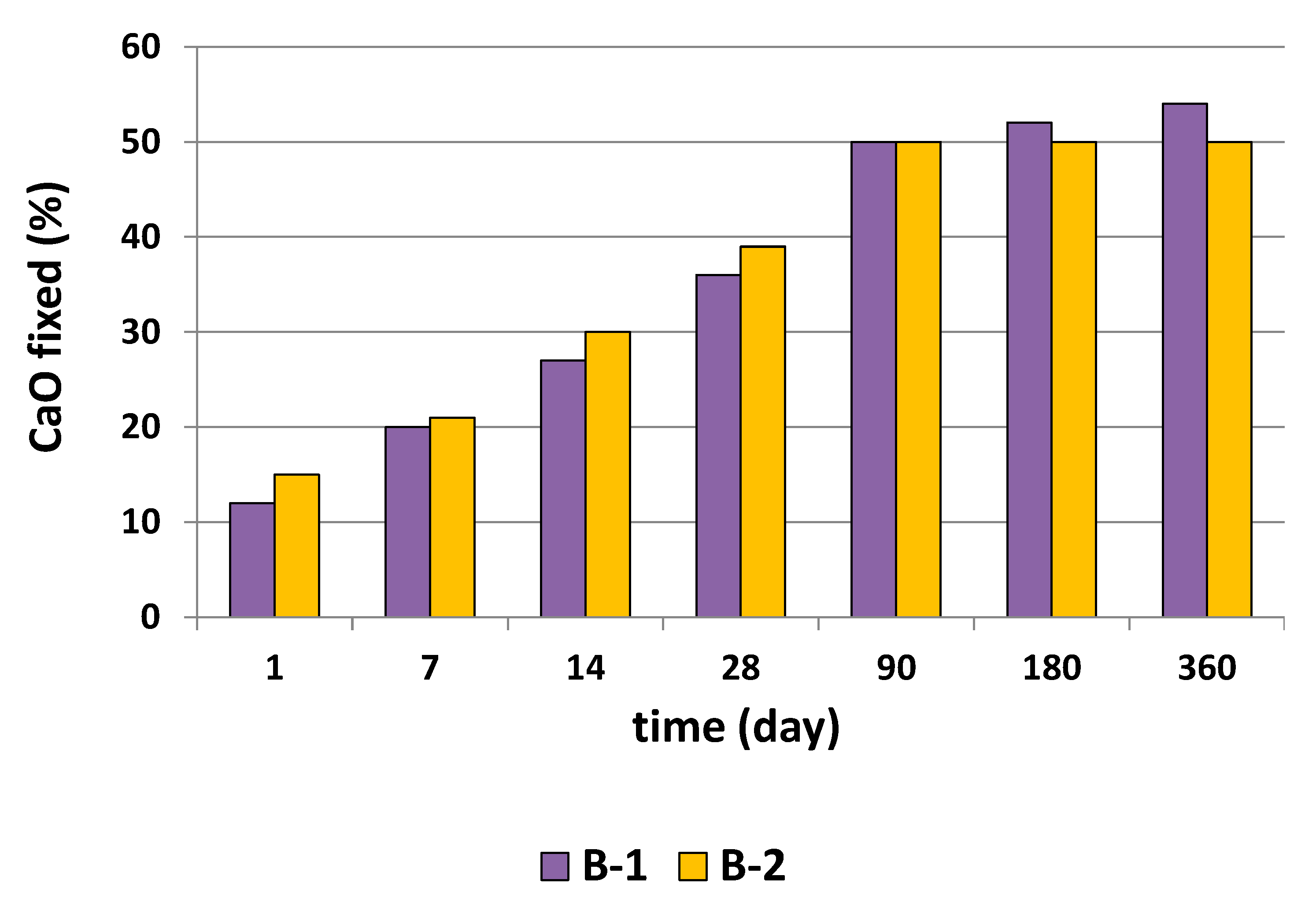
3.1.3. Pozzolanicity
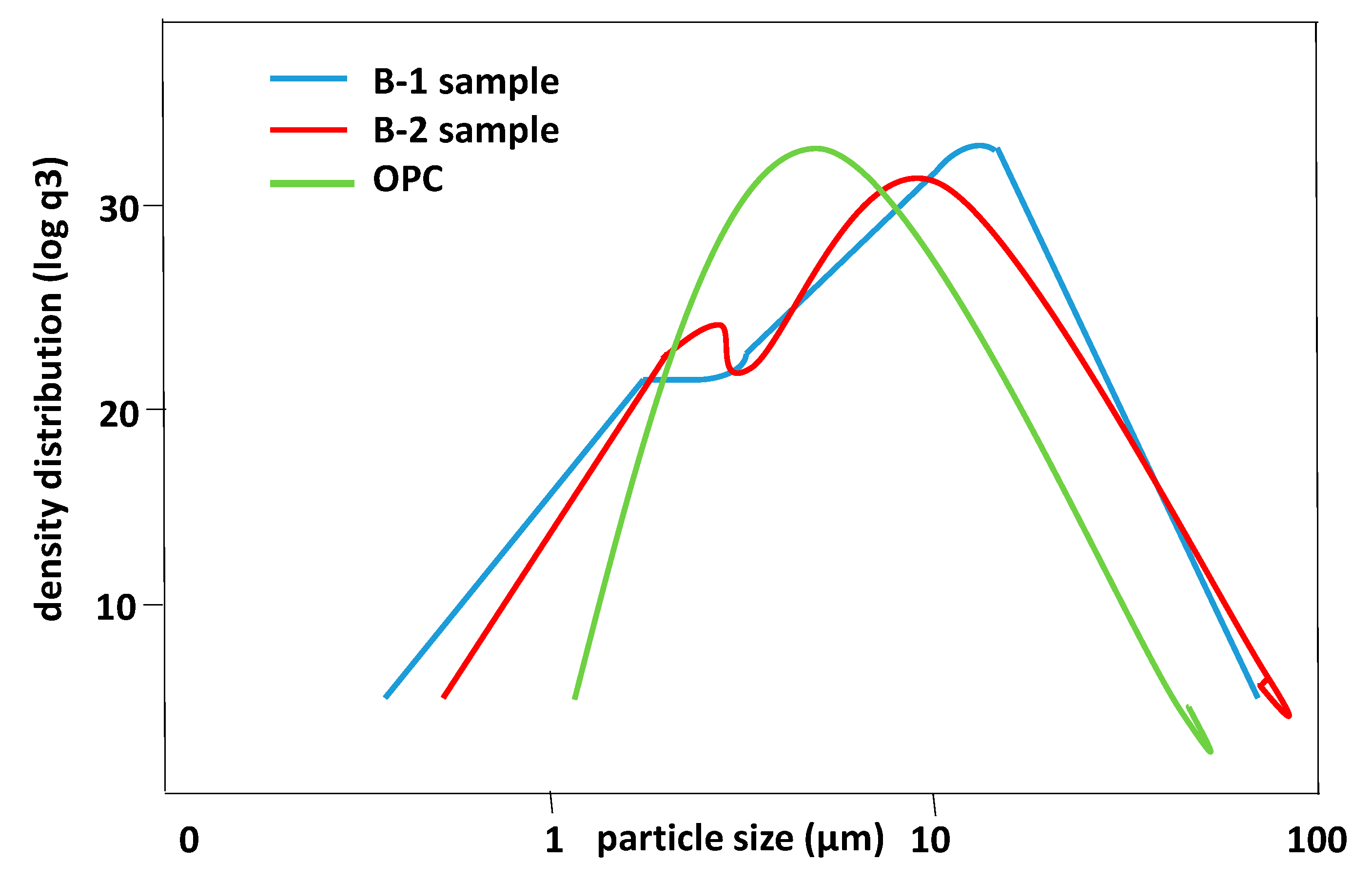
3.1.4. Particle Size
3.2. Preparation of Mortars with Ballast Waste
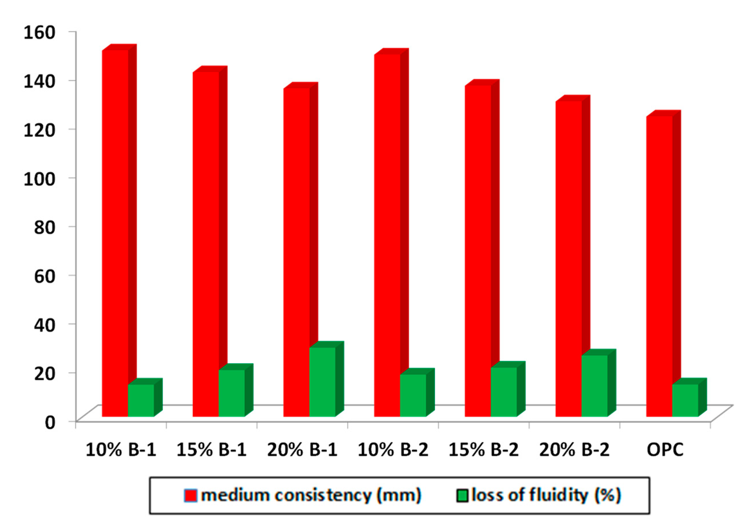
3.2.1. Workability
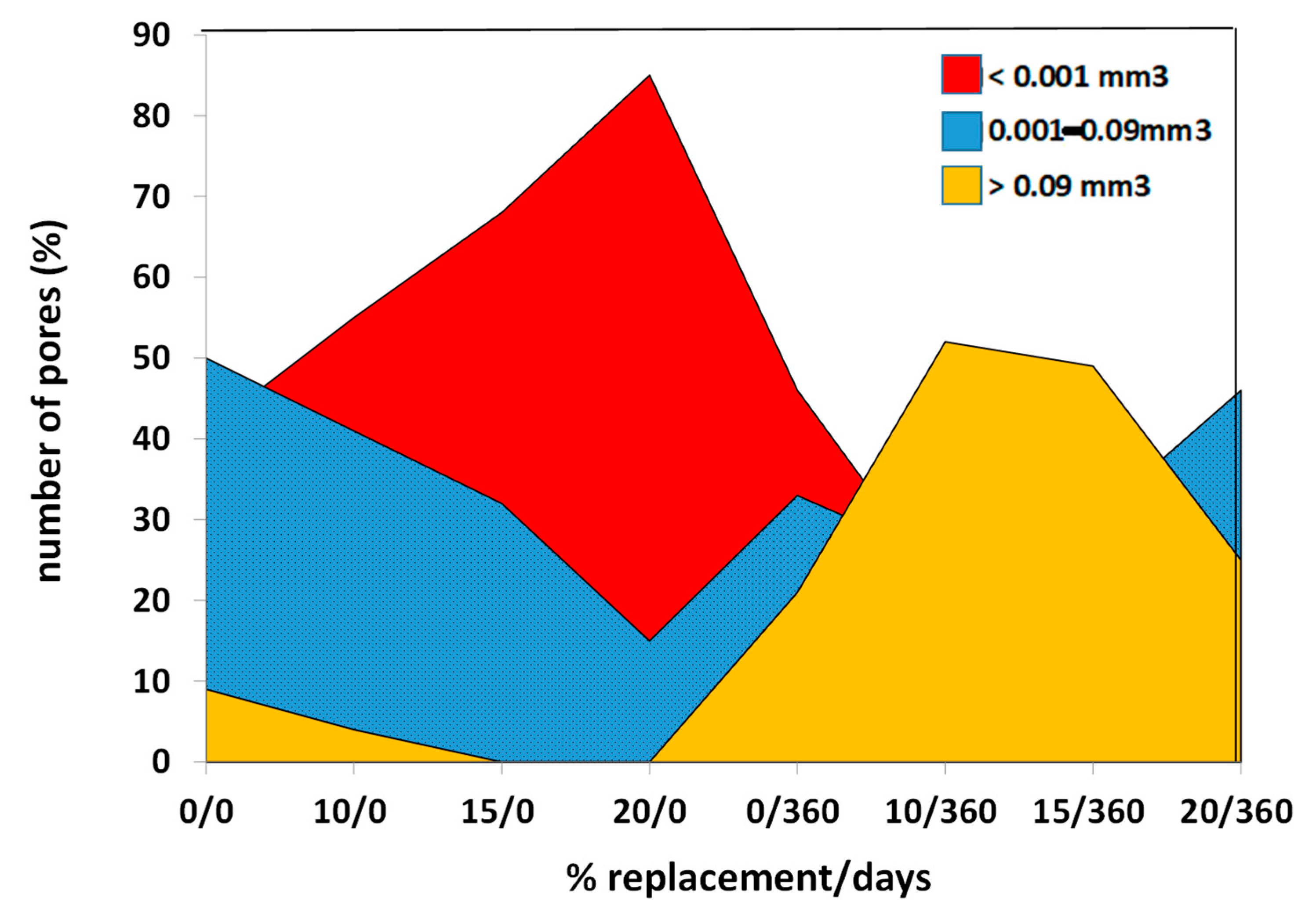
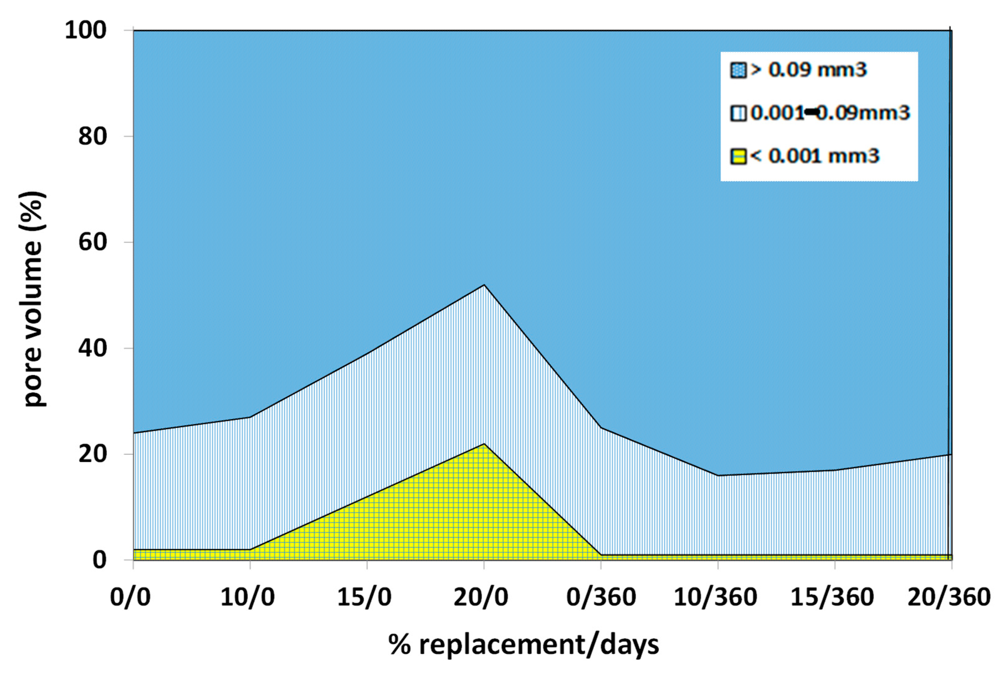
3.2.2. Porosity
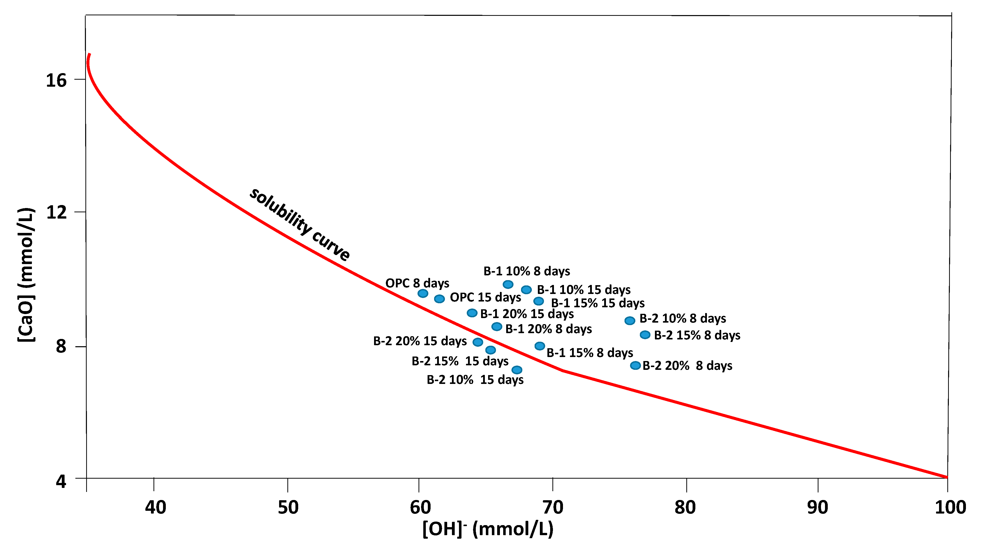
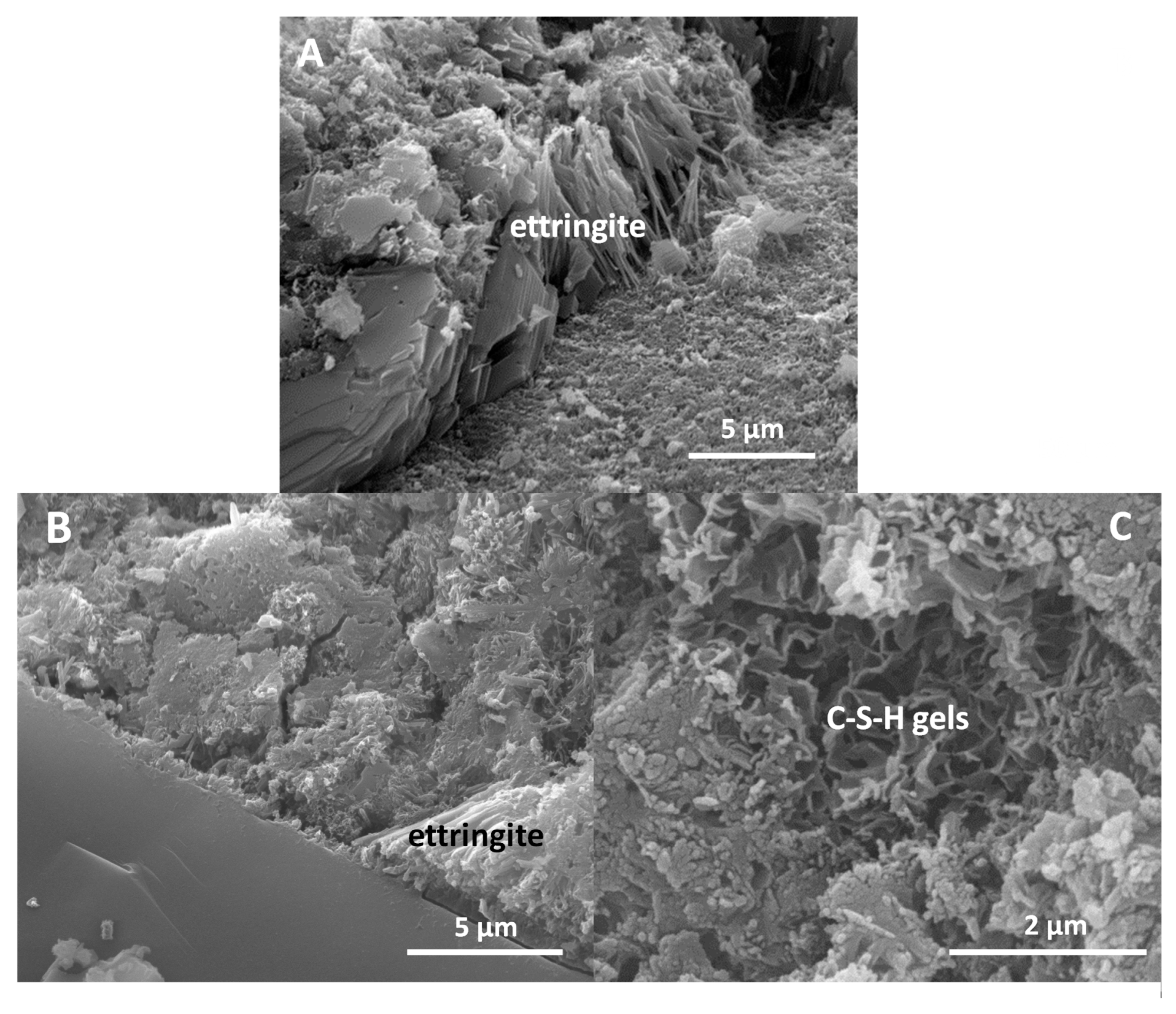
3.2.3. Pore Connectivity and Tortuosity
4. Conclusions
Author Contributions
Funding
Institutional Review Board Statement
Informed Consent Statement
Data Availability Statement
Conflicts of Interest
References
- Nimbalkar, S.; Indraratna, B.; Dash, S.K.; Christie, D. Improved Performance of Railway Ballast under Impact Loads Using Shock Mats. J. Geotech. Geoenviron. Eng. 2012, 138, 281–294. [Google Scholar] [CrossRef]
- Sheng, X.W.; Zheng, W.Q.; Zhu, Z.H.; Qin, Y.P.; Guo, J.G. Full-scale fatigue test of unit-plate ballastless track lay on long-span cable-stayed bridge. Constr. Build. Mater. 2020, 247, 118601. [Google Scholar] [CrossRef]
- Yagüe García, S.; Gonzalez Gaya, C. Durability analysis of pozzolanic cements containing recycled track ballast: Sustainability under extreme environmental conditions. Constr. Build. Mater. 2020, 242, 117999. [Google Scholar] [CrossRef]
- Neville, A.M. Properties of Concrete; Wiley: Chichester, UK, 2012. [Google Scholar]
- Kumar, R.; Bhattacharjee, B. Study on some factors affecting the results in the use of MIP method in concrete research. Cem. Concr. Res. 2003, 33, 417–424. [Google Scholar] [CrossRef]
- Elinwa, A.U.; Umar, M. X-ray diffraction and microstructure studies of gum arabic-cement concrete. Constr. Build. Mater. 2017, 156, 632–638. [Google Scholar] [CrossRef]
- Wang, X.S.; Wu, B.S.; Wang, Q.Y. Online SEM investigation of microcrack characteristics of concretes at various temperatures. Cem. Concr. Res. 2005, 35, 1385–1390. [Google Scholar] [CrossRef]
- Wyrzykowski, M.; McDonald, P.J.; Scrivener, K.L.; Lura, P. Water redistribution within the microstructure of cementitious materials due to temperature changes studied with 1H NMR. J. Phys. Chem. C 2017, 121, 27950–27962. [Google Scholar] [CrossRef]
- Zhang, J.; Bian, F.; Zhang, Y.; Fang, Z.; Fu, C.; Guo, J. Effect of pore structures on gas permeability and chloride diffusivity of concrete. Constr. Build. Mater. 2018, 163, 402–413. [Google Scholar] [CrossRef]
- Chung, S.Y.; Han, T.S.; Kim, S.Y. Reconstruction and evaluation of the air permeability of a cement paste specimen with a void distribution gradient using CT images and numerical methods. Constr. Build. Mater. 2015, 87, 45–53. [Google Scholar] [CrossRef]
- Sokhansefat, G.; Ley, M.T.; Cook, M.D.; Alturki, R.; Moradian, M. Investigation of concrete workability through characterization of aggregate gradation in hardened concrete using X-ray computed tomography. Cem. Concr. Compos. 2019, 98, 150–161. [Google Scholar] [CrossRef]
- Chung, S.Y.; Elrahman, M.A.; Stephan, D. Investigation of the effects of anisotropic pores on material properties of insulating concrete using computed tomography and probabilistic methods. Energy Build. 2016, 125, 122–129. [Google Scholar] [CrossRef]
- Zhang, H.; Šavija, B.; Lukovic, M.; Schlangen, E. Experimentally informed micromechanical modelling of cement paste: An approach coupling X-ray computed tomography and statistical nanoindentation. Compos. Part B Eng. 2019, 157, 109–122. [Google Scholar] [CrossRef]
- Han, J.; Liu, W.; Wang, S.; Du, D.; Xu, F.; Li, W.; de Schutter, G. Effects of crack and its and aggregate on carbonation penetration based on 3D micro x-ray CT microstructure evolution. Constr. Build. Mater. 2016, 128, 256–271. [Google Scholar] [CrossRef]
- Liu, J.; Ba, M.; Du, Y.; He, Z.; Chen, J. Effects of chloride ions on carbonation rate of hardened cement paste by x-ray CT techniques. Const. Build. Mater. 2016, 122, 619–627. [Google Scholar] [CrossRef]
- Cui, D.; Banthia, N.; Wang, Q.; Sun, W. Investigation on porosity of partly carbonated paste specimens blended with fly ash through dual CT scans. Constr. Build. Mater. 2019, 196, 692–702. [Google Scholar] [CrossRef]
- Shields, Y.; Garboczi, E.; Weiss, J.; Farnam, Y. Freeze-thaw crack determination in cementitious materials using 3D X-ray computed tomography and acoustic emission. Cem. Concr. Compos. 2018, 89, 120–129. [Google Scholar] [CrossRef]
- Qi, B.; Gao, J.; Chen, F.; Shen, D. Chloride penetration into recycled aggregate concrete subjected to wetting-drying cycles and flexural loading. Constr. Build. Mater. 2018, 174, 130–137. [Google Scholar] [CrossRef]
- Gallucci, E.; Scrivener, K.; Groso, A.; Stampanoni, M.; Margaritondo, G. 3D experimental investigation of the microstructure of cement pastes using synchrotron X-ray microtomography. Cem. Concr. Res. 2007, 37, 360–368. [Google Scholar] [CrossRef]
- Bossa, N.; Chaurand, P.; Vicente, J.; Borschneck, D.; Levard, C.; Chariol, O.A.; Rose, J. Micro- and nano-X-ray computed-tomography: A step forward in the characterization of the pore-network of a leached cement paste. Cem. Concr. Res. 2015, 67, 138–147. [Google Scholar] [CrossRef]
- du Plessis, A.; Olawuyi, B.; Boshoff, W.; le Roux, S. Simple and fast porosity analysis of concrete using X-ray computed tomography. Mater. Struct. 2016, 49, 553–562. [Google Scholar] [CrossRef]
- Lu, S.; Landis, E.; Keane, D. X-ray microtomographic studies of pore structure and permeability in Portland cement concrete. Mater. Struct. 2006, 36, 11–20. [Google Scholar]
- Chotard, T.; Boncoeur-Martel, M.; Smith, A.; Dupuy, J.; Gault, C. Application of X ray computed tomography to characterise the early hydration of calcium aluminate cement. Cem. Concr. Compos. 2003, 25, 145–152. [Google Scholar] [CrossRef]
- Helfen, L.; Dehn, F.; Mikulik, P.; Baumbach, T. Three-dimensional imaging of cement microstructure evolution during hydration. Adv. Cem. Res. 2007, 17, 103–111. [Google Scholar] [CrossRef]
- Gastaldi, D.; Canonico, F.; Capelli, L.; Boccaleri, E.; Milanesio, M.; Palin, L.; Croce, G.; Marone, F.; Mader, K.; Stampanoni, M. In situ tomographic investigation on the early hydration behaviors of cementing systems. Constr. Build. Mater. 2012, 29, 284–290. [Google Scholar] [CrossRef]
- Zhang, M.; Jivkov, A. Micromechanical modelling of deformation and fracture of hydrating cement paste using X-ray computed tomography characterisation. Compos. Part B Eng. 2016, 88, 64–72. [Google Scholar] [CrossRef]
- Yang, Y.; Zhang, Y.; She, W.; Wu, Z.; Liu, Z.; Ding, Y. Nondestructive monitoring the deterioration process of cement paste exposed to sodium sulfate solution by X-ray computed tomography. Constr. Build. Mater. 2018, 186, 182–190. [Google Scholar] [CrossRef]
- Zhang, M.; He, Y.; Lange, D.; Breggel, K. Computational investigation on mass diffusivity in Portland cement paste based on X-ray computed microtomography image. Constr. Build. Mater. 2012, 27, 472–481. [Google Scholar] [CrossRef]
- Ghiasvand, E.; Ramezanianpour, A.A.; Ramezanianpour, A.M. Effect of grinding method and particle size distribution on the properties of Portland-pozzolan cement. Constr. Build. Mater. 2014, 53, 547–554. [Google Scholar] [CrossRef]
- Mehta, P.K. Studies on blended Portland cements containing santorin earth. Cem. Concr. Res. 1981, 11, 507–518. [Google Scholar] [CrossRef]
- Taylor, H.F.W. Cement Chemistry; Thomas Telford: London, UK, 1997. [Google Scholar]
- Lea, F.M. The Chemistry of Cement and Concrete; First Amer: New York, NY, USA, 1971. [Google Scholar]
- John, E.; Lothenbach, B. Cement hydration mechanisms through time-a review. J. Mater. Sci. 2023, 58, 9805–9833. [Google Scholar] [CrossRef]
- Deschner, F.; Winnefeld, F.; Lothenbach, B.; Seufert, S.; Schwesig, P.; Dittrich, S.; Goetz Neunhoeffer, F.; Neubauer, J. Hydration of Portland cement with high replacement by siliceous fly ash. Cem. Concr. Res. 2012, 42, 1389–1400. [Google Scholar] [CrossRef]
- Ardoğa, M.K.; Erdoğan, S.T.; Tokyay, M. Effect of particle size on early heat evolution of interground natural pozzolan blended cements. Constr. Build. Mater. 2019, 206, 210–218. [Google Scholar] [CrossRef]
- Hamada, H.M.; Abdulhaleem, K.N.; Majdi, A.; Al Jawahery, M.S.; Skariah Thomas, B.; Yousif, S.T. The durability of concrete produced from pozzolan materials as a partially 625 cement replacement: A comprehensive review. Mat. Today Proc. 2023. [Google Scholar] [CrossRef]
- Uzal, B.; Turanli, L. Studies on blended cements containing a high volume of natural pozzolans. Cem. Concr. Res. 2003, 33, 1777–1781. [Google Scholar] [CrossRef]
- UNE-EN 1097-2; Ensayos para Determinar las Propiedades Mecánicas y Físicas de los Áridos; Parte 2: Métodos para la Determinación de la Resistencia a la Fragmentación. Asociación Española de Normalización y Certificación: Madrid, Spain, 2010.
- UNE-EN 13450; Áridos para Balasto. Asociación Española de Normalización y Certificación: Madrid, Spain, 2003.
- Martín Serrano, A.; del Olmo Sanz, A.; Bellido Mulas, F.; Fuster, J.; Navidad, M.; de Pablo Macía, J.; Villaseca, C. Hoja 1:50.000, el Espinar; Serie Magna; IGME: Madrid, Spain, 1991. [Google Scholar]
- Martín Parra, L.; Martínez Salanova, I.; Moreno, F. Hoja 1:50.000, Ávila de los Caballeros; Serie Magna; IGME: Madrid, Spain, 2008. [Google Scholar]
- ISO/TC 74; Cement and Lime. International Organization for Standardization: Geneva, Switzerland, 2009.
- C150-07; Standard Specification for Portland Cement. ASTM International: West Conshohocken, PA, USA, 2007.
- ASTM C666-97; Standard Test Method for Resistance of Concrete to Rapid Freezing and Thawing. ASTM International: West Conshohocken, PA, USA, 2017.
- ASTM C469; Standard Test Method for Static Modulus of Elasticity and Poisson’s Ratio of Concrete in Compression. ASTM International: West Conshohocken, PA, USA, 2010.
- Ostrowski, K.; Stefaniuk, D.; Sadowski, L.; Krzywinski, K.; Rozanska, M. Potential use of granite waste sourced from rock processing for the application as coarse aggregate in high-performance self-compacting concrete. Constr. Build. Mat. 2020, 238, 117–794. [Google Scholar] [CrossRef]
- UNE-EN 196-1; Métodos de Ensayo de Cementos. Parte I. Determinación de Resistencias Mecánicas. Asociación Española de Normalización y Certificación: Madrid, Spain, 2018.
- UNE-EN 196-5; Métodos de Ensayo de Cementos. Parte 5: Ensayo de Puzolanicidad para los Cementos Puzolánicos. Asociación Española de Normalización y Certificación: Madrid, Spain, 2011.
- Souri, A.; Kazemi-Kamyab, H.; Snellings, R.; Naghizadeh, R.; Golestani-Fard, F.; Scrivener, K. Pozzolanic activity of mechanochemically and thermally activated kaolins in cement. Cem. Concr. Res. 2015, 77, 47–59. [Google Scholar] [CrossRef]
- Medina, G.; Sáez del Bosque, I.F.; Frías, M.; Sánchez de Rojas, M.I.; Medina, C. Mineralogical study of granite waste in a pozzolan/Ca(OH)2 system. Influence of the activation process. Appl. Clay Sci. 2017, 135, 362–371. [Google Scholar] [CrossRef]
- Richardson, I.G. The nature of the hydration products in hardened cement pastes. Cem. Concr. Comp. 2000, 22, 97–113. [Google Scholar] [CrossRef]
- Sabir, B.B.; Wild, S.; Bai, J. Metakaolin and a calcined clays as pozzolans for concrete: A review. Cem. Concr. Comp. 2001, 23, 441–454. [Google Scholar] [CrossRef]
- Qian, X.; Li, Z. The relationships between stress and strain for high performance concrete with metakaolin. Cem. Concr. Res. 2001, 31, 1607–1611. [Google Scholar] [CrossRef]
- Sabir, B.B.; Wild, S.; Khabit, J.M. On the workability and strength development of metakaolin concrete. In Proceedings of the International Conference Concrete in the Service of Mankind, Dundee, UK, 24–28 June 1996; pp. 651–661. [Google Scholar]
- Jones, T.R. Metakaolin as a Pozzolanic Addition to Concrete. In Structure and Performance of Cements, 2nd ed.; Bensted, J., Barnes, P., Eds.; Spon Press: London, UK, 2002; pp. 372–398. [Google Scholar]
- UNE-EN 197-1; Cemento. Parte I: Composición, Especificaciones y Criterios de Conformidad de los Cementos Comunes. Asociación Española de Normalización y Certificación: Madrid, Spain, 2011.
- Juenger, M.C.G.; Siddique, R. Recent advances in understanding the role of supplementary cementitious materials in concrete. Cem. Concr. Res. 2015, 78, 71–80. [Google Scholar] [CrossRef]
- Shah, V.; Mackechnie, J.; Scott, A. Determination of carbonation resistance of concrete through a combination of cement content and tortuosity. J. Build. Eng. 2022, 60, 105176. [Google Scholar] [CrossRef]
- Fonseca, P.C.; Jennings, H.M. The effect of drying on early-age morphology of C-S-H as observed in environmental SEM. Cem. Concr. Res. 2010, 40, 1673–1680. [Google Scholar] [CrossRef]
- Bullard, J.W.; Jennings, H.M.; Livingston, R.A.; Nonat, A.; Scherer, G.W.; Schweitzer, J.S.; Scrivener, K.L.; Thomas, J.J. Mechanisms of cement hydration. Cem. Concr. Res. 2011, 41, 1208–1223. [Google Scholar] [CrossRef]
- Gallucci, E.; Zhang, X.; Scrivener, K.L. Effect of temperature on the microstructure of calcium silicate hydrate (C-S-H). Cem. Concr. Res. 2013, 53, 185–195. [Google Scholar] [CrossRef]
- Gartner, E.; Maruyama, I.; Chen, J. A new model for the C-S-H phase formed during the hydration of Portland cements. Cem. Concr. Res. 2017, 97, 95–106. [Google Scholar] [CrossRef]
- Vervoort, R.W.; Cattle, S.R. Linking hydraulic conductivity and tortuosity parameters to pore space geometry and pore-size distribution. J. Hydrol. 2003, 272, 36–49. [Google Scholar] [CrossRef]
- Salmas, C.E.; Androutsopoulos, G.P. A novel pore structure tortuosity concept based on nitrogen sorption hysteresis data. Ind. Eng. Chem. Res. 2001, 40, 721–730. [Google Scholar] [CrossRef]
- Bernardo, G.; Telesca, A.; Valenti, G.L. A porosimetric study of calcium sulfoaluminate cement pastes cured at early ages. Cem. Concr. Res. 2006, 36, 1042–1047. [Google Scholar] [CrossRef]
- Mohan, M.K.; Rahul, A.V.; Van Stappen, J.F.; Cnudde, V.; De Schutter, G.; Van Tittelboom, K. Assessment of pore structure characteristics and tortuosity of 3D printed concrete using mercury intrusion porosimetry and X-ray tomography. Cem. Concr. Comp. 2023, 140, 105104. [Google Scholar] [CrossRef]


| Ballast Waste | RB | Χ2 | Biotite (%) | Kaolinite (%) | Quartz (%) | Orthoclase (%) | Albite (%) | Amorphous Material (%) | Hematite (%) | Labradorite (%) |
|---|---|---|---|---|---|---|---|---|---|---|
| B-1 | 16.5 | 3.3 | 30 | 7 | 29 | 6 | 14 | 10 | 4 | n.d. |
| B-2 | 12.3 | 3.5 | 35 | 6 | 21 | 5 | n.d. | 6 | 4 | 23 |
| Oxides (%) | B-1 Sample | B-2 Sample |
|---|---|---|
| Na2O | 2.97 | 4.78 |
| MgO | 1.72 | 0.95 |
| Al2O3 | 13.79 | 19.60 |
| K2O | 2.85 | 4.06 |
| CaO | 2.77 | 3.26 |
| MnO | 0.11 | 0.03 |
| TiO2 | 0.80 | 0.37 |
| Fe2O3 | 6.72 | 3.49 |
| SiO2 | 68.27 | 63.49 |
| LOI | 0.67 | 1.22 |
Disclaimer/Publisher’s Note: The statements, opinions and data contained in all publications are solely those of the individual author(s) and contributor(s) and not of MDPI and/or the editor(s). MDPI and/or the editor(s) disclaim responsibility for any injury to people or property resulting from any ideas, methods, instructions or products referred to in the content. |
© 2025 by the authors. Licensee MDPI, Basel, Switzerland. This article is an open access article distributed under the terms and conditions of the Creative Commons Attribution (CC BY) license (https://creativecommons.org/licenses/by/4.0/).
Share and Cite
Yagüe-García, S.; García-Giménez, R. Microstructure of Mortar with Ballast Waste as a Cement Replacement. Appl. Sci. 2025, 15, 5605. https://doi.org/10.3390/app15105605
Yagüe-García S, García-Giménez R. Microstructure of Mortar with Ballast Waste as a Cement Replacement. Applied Sciences. 2025; 15(10):5605. https://doi.org/10.3390/app15105605
Chicago/Turabian StyleYagüe-García, Santiago, and Rosario García-Giménez. 2025. "Microstructure of Mortar with Ballast Waste as a Cement Replacement" Applied Sciences 15, no. 10: 5605. https://doi.org/10.3390/app15105605
APA StyleYagüe-García, S., & García-Giménez, R. (2025). Microstructure of Mortar with Ballast Waste as a Cement Replacement. Applied Sciences, 15(10), 5605. https://doi.org/10.3390/app15105605