Abstract
With the rapid development of renewable energy technologies, large numbers of photovoltaic (PV) and battery energy storage systems (BESS) have been connected to distribution networks. However, both PV and the BESS are inverter interfaced power sources, which may cause the traditional protection relays to mis-operate or mal-operate. Moreover, according to the latest grid connection specifications, PV and BESS are required to absorb negative sequence current during asymmetric faults of distribution networks, indicating that they both must adopt new control strategies during the fault ride through period. In response to the above challenges, this work first studies the fault ride through control strategies of PV and BESS when different phase-to-phase faults occur according to the latest grid connection requirements. Second, it analyzes the negative sequence impedance characteristics of PV and BESS under asymmetric faults and quantitatively calculates its variation range. Third, during symmetric faults, the differences in fault current provided by PV and BESS and those provided by the large power grid are compared. Then, this work proposes a fault direction detection principle for the distribution network with PV and BESS. For asymmetric phase-to-phase faults, this principle detects the fault direction by using the negative sequence power angle; for symmetric faults, it detects the fault direction by using the reactive current and active current. Finally, simulation tests are carried out to verify the operation performance of the proposed principle.
1. Introduction
To achieve the “dual-carbon” goals, China is accelerating the development of the power grid with a high percentage of renewable energy. BESS can balance the intermittency of PV generation by storing excess electricity during periods of sufficient sunlight and releasing it during peak demand or insufficient sunlight, thereby ensuring stable power supply and enhancing grid reliability and flexibility. Under these circumstances, an increasing number of PV and BESS are being connected to the distributed networks every year. However, the large scale of PV and BESS has obviously increased the complexity of the power grid [1,2,3,4]. PV and BESS belong to the category of inverter interfaced resources (IIR) [5]. In a distribution network with IIR connected, the directional overcurrent protection may suffer from protection failure issues due to the altered fault current characteristics of the distribution network caused by the IIR connection [6,7]. This brings a series of new technical challenges to the protection of the power system [8,9,10].
References [11,12] analyzed the fault characteristics of PV employing negative sequence current suppression strategies for FRT, respectively. However, recent grid connection specifications require PV and BESS to absorb negative sequence current during asymmetric faults to suppress the negative sequence voltage at the point of Common Coupling (PCC). In response to the new grid connection requirements, References [13,14] proposed an FRT control strategy to comply with the newly emerging grid codes and FRT requirements. In addition, current research on directional elements mainly focuses on distribution networks connected with PV or wind power [15,16,17], and there is relatively little research on new directional elements for distribution networks connected with PV and BESS. Reference [18] presented an approach for identifying fault for distribution networks with PV through negative sequence current magnitude analysis during asymmetric faults. However, the applicability of this approach to PV and BESS systems implementing different FRT control strategies remains undetermined. Reference [19] introduced a directional protection scheme utilizing both amplitude and phase attributes of injected negative-sequence impedance for asymmetric fault orientation. For balanced fault scenarios, Reference [20] established a detection mechanism based on positive-sequence impedance variations combined with active power angle measurements, integrated with supplementary directional estimation logic. Notably, the strategies in References [19,20] were specifically designed for negative sequence current suppression control architectures, leaving their validity under negative sequence current absorption control strategies unverified.
Aiming at the above-mentioned deficiencies, this work discusses the fault characteristics and protection principle for the distribution networks with PV and BESS. First, it studies the FRT control strategy of PV and BESS under negative sequence current absorption. Then, it analyzes the negative sequence impedance characteristics of PV and BESS connected to the distribution network during asymmetric phase-to-phase faults and the distribution of active and reactive currents during symmetric faults. Finally, a fault direction detection principle is proposed, which is based on the negative sequence impedance angle during asymmetric faults and uses the reactive current and the active current during symmetric faults. The proposed principle is verified by simulation results.
2. Fault Characteristics of the Distribution Networks with PV and BESS
The structural diagram of a distribution network at a certain location in Tianjin connected with PV and BESS is shown in Figure 1. Due to the connection of PV and BESS, the traditional single source radial distribution network has transformed into a complex network with dual power sources or even multiple power sources. Therefore, for a transmission line with dual power sources, the overcurrent relay on the side of the inverter interfaced resource (IIR) requires a directional element to form a directional overcurrent relay [21], such as PR4. Since PV and BESS belong to the IIR category, and the fault characteristics of PV and BESS are significantly different from those of synchronous power sources, the traditional power distribution element either malfunctions or refuses to operate. To solve this problem, this section analyzes the fault characteristics when a symmetric fault or asymmetric phase-to-phase fault occurs in a distribution network at a certain location in Tianjin connected with PV and BESS. Table 1 shows the specific parameters of the system:
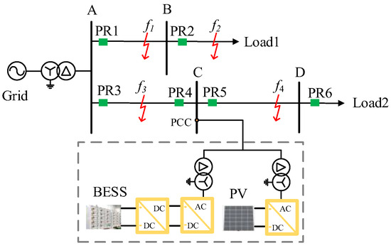
Figure 1.
Structural diagram of a distribution network at a certain location in Tianjin connected with PV and BESS.

Table 1.
Specific parameters of the distribution network with PV and BESS.
2.1. FRT Control Strategy of PV and BESS
2.1.1. Symmetric Faults
According to the current grid connection standard GB/T 34120-2023 [22], “Technical requirements for power conversion system of electrochemical energy storage system”, during symmetric faults, the PV and BESS should operate in FRT mode and inject positive sequence reactive current into the network to support the voltage at the PCC. Since the inverters used in both the PV and the BESS adopt the constant power control method, their control strategies during the fault period are similar. The details are as follows: During symmetric faults, similar to the conventional negative sequence current suppression control strategy, priority is typically given to controlling reactive power to provide voltage support for the system. Since the PV and BESS controls the reactive power magnitude by adjusting the reactive current component, when a fault occurs causing a voltage variation at the PCC, the positive sequence reactive current reference value can be adjusted based on the voltage sag level at the PCC of the PV and BESS system to regulate the reactive power delivered by the PV and BESS, with specific values specified in the grid connection standards. Meanwhile, due to the output current limitations of PV and BESS, the positive sequence active current reference value is determined by , as shown in Equation (1).
Among them, is the phase voltage vector at PCC; is the rated line voltage of the distribution network; is the rated phase current of the PV and the BESS output; is the positive sequence active power current command value given by the DC voltage outer loop when the system is not in a fault state; and are the proportional and integral coefficients of the DC voltage outer loop in the constant power control mode; and are the reference and actual values of the DC voltage under constant power control mode respectively; is the output current limit.
2.1.2. Asymmetrical Phase-to-Phase Faults
Since the new grid connection specifications require the adoption of a negative sequence current absorption strategy, during asymmetric phase-to-phase faults, the PV and BESS should not only output positive sequence reactive current but also absorb negative sequence reactive current to limit the negative sequence voltage at the PCC. During asymmetric faults, when the output reactive current does not exceed the limit, the positive sequence reactive current reference value and the positive sequence active current reference value are determined by the same method as during symmetric faults. However, unlike the conventional negative sequence current suppression control strategy, the negative sequence current absorption strategy specifies the negative sequence reactive current reference value through the grid connection standards. Nevertheless, when the reactive current exceeds the limit, proportional redistribution of A and B is required to prevent single-phase overcurrent. The corresponding FRT strategy is shown in Equation (2).
where and are the reference values before the redistribution of positive sequence reactive current and negative sequence reactive current; is the negative sequence phase voltage vector at PCC; and are the reference values after the redistribution of positive sequence reactive current and negative sequence reactive current; and are the actual reference values of positive sequence reactive current and negative sequence reactive current; represents the reference value of positive sequence active power current.
2.2. Negative Sequence Impedance Characteristics of the Network During Asymmetric Faults
When an asymmetric fault occurs on the line and the positive sequence voltage at the PCC of the PV and the BESS drops below 0.9 p.u., the PV and BESS need to absorb a certain amount of negative sequence reactive current to suppress the negative sequence voltage at the PCC. It should be made clear that, to absorb negative sequence reactive power for negative sequence voltage suppression, the phase of the negative sequence current vector emitted should lead the negative sequence voltage vector at the PCC by 90°. This means that the negative sequence impedance of the PV and the BESS is purely inductive, with an impedance angle of 90°. When the output reactive current of the PV and the BESS does not reach the limit value, the negative sequence impedance of the PV and the BESS remains constant, as Equation (3) shows:
Among them, is the negative sequence impedance of the PV and the BESS; is a constant, and its value is taken as 2 in this work; defines the rated capacity of the PV and BESS.
When the output reactive current of the PV and BESS reaches the limit value, the negative sequence reactive current output is redistributed according to Equation (2), and the negative sequence impedance exceeds the value specified in Equation (3).
Next, taking the topological structure in Figure 1 as an example, the negative sequence impedance measured by PR4 is analyzed when a two-phase short-circuit fault occurs in the forward direction area or the reverse direction area of PR4. The forward protection zone is designated from Bus C to A, while the reverse protection zone is designated from Bus C to D. Figure 2 illustrates the composite sequence network associated with the two-phase short-circuit fault occurring in the system depicted in Figure 1.
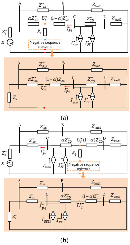
Figure 2.
(a) Composite sequence network when two-phase short-circuit faults occur at f3. (b) Composite sequence network when two-phase short-circuit faults occur at f4.
For PR4, if a fault occurs on line AB or line AC, the measured negative sequence impedance is opposite to the equivalent negative sequence impedance downstream of bus C. Since the negative sequence impedance angle of PV and BESS is 90°, the equivalent impedance obtained by paralleling it with the line and load impedance remains resistive-inductive, and the impedance angle is within the range from 0° to 90°. Therefore, when a forward fault occurs, the phase angle of the negative sequence impedance measured at PR4 is within the range from −180° to −90°. When a fault occurs on line CD, the measured impedance of PR4 reflects the equivalent negative sequence impedance upstream of bus C, and its phase angle is approximately equal to the angle of the line impedance. This implies that, when a forward fault occurs, the negative sequence impedance angle measured by PR4 at this time is within the range from 0° to 90°. From the above analysis, it can be seen that, in the case of asymmetric faults, it is feasible to estimate the fault direction by using the negative sequence power flow detected at PR4.
When a reverse fault occurs, the change in the negative sequence measured impedance of PR4 is determined by the operation mode of the system and can be obtained from the system parameters. However, when a forward fault occurs, the specific boundaries of the amplitude and phase changes of the negative sequence measured impedance of PR4 are not clear. Therefore, it is necessary to determine the variation range of the negative sequence impedance of PV and BESS.
Under the same transition resistance, the closer the fault location is to bus C, the smaller the positive sequence voltage at bus C, and the larger the negative sequence voltage. At this time, the PV and BESS need to output more positive sequence active current and absorb more negative sequence reactive current, and it is very likely to reach the reactive current limit, thus making the negative sequence impedance of the PV and the BESS greater than the value in Equation (3).
When the fault location is the same, the smaller the transition resistance, the smaller the positive sequence voltage at bus C and the larger the negative sequence voltage. Similarly, in this case, it is also easier to reach the reactive current limit, making the negative sequence impedance of the PV and BESS greater than the value in Equation (3). In conclusion, the negative sequence impedance of the PV and the BESS is the largest when the system is in the minimum operation mode and a forward outlet metallic two-phase short-circuit fault occurs.
2.3. Reactive Current Distribution in Fault Network Under Symmetrical Faults
It is not practical to determine the fault direction merely using negative sequence quantities during symmetric faults, and the PV, BESS, and the synchronous power source all output reactive current during faults. Therefore, the flow direction of reactive current can be utilized to identify the fault direction.
As shown in Figure 1, when a forward fault occurs, in most cases, the reactive current will flow from the bus C to the fault point, and the reactive current detected at PR4 will be larger than zero. In a few cases, when the fault location is far from bus C and the fault resistance is large, the reactive current from the PV and BESS is low, and at this time, the reactive current detected by PR4 will be less than zero.
When a reverse fault occurs, in most cases, the reactive current flows from line AC to bus C. At this time, the reactive current detected by PR4 is less than zero. In a few cases, when the fault point is located in line CD close to bus C, the voltage drop of bus C is large, and the reactive current emitted by the PV and BESS is large while the reactive current consumed downstream of bus C is low, then the reactive current detected by PR4 will be greater than zero.
2.4. Active Current Distribution in Fault Network Under Symmetrical Faults
Since it is impossible to distinguish between a forward fault and a reverse near end fault solely based on the flow direction of reactive current, and considering the limited ability of PV and BESS to provide fault current and the priority of outputting reactive current during faults, further analysis is required to compare the difference between the amplitude of the active current output by the PV and BESS and the amplitude of the active current output by the synchronous power source.
If a forward fault occurs, the active current flowing through PR4 is the active current output by the PV and BESS minus the active current of the downstream load, and the amplitude of the active current detected by PR4 at this time is limited. If a reverse near end fault occurs, the fault current flowing through PR4 is provided by the synchronous power source, and its amplitude is determined by the fault network. At this time, the amplitude of the active current detected by PR4 is usually much larger than that during normal operation.
Considering the extreme situation, when the system is in the minimum operation mode, the installed capacity of the PV and BESS increases to 18 MVA, so that the system short circuit ratio reaches 3. The fault location and fault resistance are changed, and the above iterative method is used to solve the maximum amplitude of the active current flowing through PR4 when a forward fault occurs, and the minimum amplitude of the active current flowing through PR4 when a reverse near end (15%) fault occurs. The calculation results are 0.86 kA and 1.6 kA, respectively.
3. The Proposed Fault Direction Detection Principle
3.1. Principle for Detecting Fault Direction Under Asymmetric Phase-to-Phase Faults
3.1.1. Voltage Blocking Criterion for Asymmetric Phase-to-Phase Faults
The fault direction detection principle described in this section is specifically for two-phase short-circuit faults. Therefore, after the protection device is activated, it should first determine the type of fault according to the amplitude of the negative sequence voltage. When it is determined that the fault is not a two-phase short-circuit fault, the direction criterion should be blocked. At the same time, since the above analysis is carried out based on the FRT process of the PV and BESS, the direction criterion will only be enabled when the positive sequence voltage at the PCC is detected to be lower than 0.9 p.u. In summary, for PR4, when the detected positive sequence voltage and negative sequence voltage satisfy the equation shown in Formula (4), the negative sequence power direction criterion is activated; otherwise, the direction criterion will be blocked.
The voltage blocking criterion is as follows:
Among them, and are reliability coefficients, with values of 0.98 and 0.95 respectively. is the maximum value of the positive sequence voltage at the protection installation point, which is set according to the maximum positive sequence voltage when the PV and BESS enter the FRT state. is the minimum value of the negative sequence voltage at the protection installation point, which refers to the negative sequence voltage value measured at the protection relay location when a fault with the maximum fault resistance (10 Ω) occurs at the end of the forward or reverse region under the maximum operating mode of the system. After substituting the system parameters for the calculation, and are set as 5.0964 kV and 0.2952 kV, respectively.
3.1.2. Negative Sequence Impedance Angle Direction Criterion
The negative sequence impedance angle direction criterion is shown in Equation (5):
Among them, and are the upper and lower boundaries of the operating region during forward faults, and they can be calculated using Equations (6) and (7):
where and are the maximum and minimum negative sequence impedance upstream of PR4, and and are the maximum and minimum negative sequence impedance downstream of PR4. Substituting the system parameters into Equations (6) and (7) yields values of −15.19° for and −178.78° for .
The flowchart of the proposed principle in this section is shown in Figure 3.
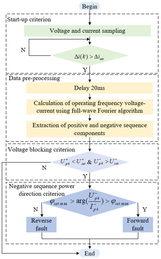
Figure 3.
Principle for detecting fault direction during asymmetric phase-to-phase faults.
3.2. Principle for Detecting Fault Direction Under Symmetric Faults
3.2.1. Voltage Blocking Criterion for Symmetric Faults
Similar to the voltage blocking criterion proposed in Section 3.1.1, when the positive sequence voltage and negative sequence voltage at the installation location of the protection device satisfy the equation shown in Equation (8), the reactive current direction criterion should be activated; otherwise, the direction criterion will be blocked.
where and are reliability factors, taking values of 0.98 and 0.95 respectively. is the voltage at the installation point of the protection device when the reactive current detected by PR4 is 0 during a forward fault. is defined in the same way as in Section 3.1.1. After substituting the system parameters for calculation, and are set as 4.6126 kV and 0.2952 kV, respectively.
3.2.2. Reactive Current Direction and Active Current Amplitude Direction Criterion
As analyzed in Section 2.3, during three-phase short-circuit faults, the reactive current through PR4 is positive in its forward area and negative in its reverse area. When a three-phase short-circuit fault occurs in the reverse area of PR4, the reactive current flowing through PR4 is less than 0. Therefore, the fault direction can be judged based on the flow direction of the reactive current. However, considering the calculation error of the short circuit current, 0 cannot be used as the critical value. A critical value needs to be set. Only when the absolute value of the detected reactive current exceeds this threshold does its positive/negative sign reliably indicate the current flow direction. Taking PR4 as an example, at this time, the fault criterion for the reverse area is shown in Equation (9):
where takes the value of 0.05 kA.
If the detected amplitude of the reactive current exceeds the set value and its sign is positive, or the amplitude of the reactive current is less than the set value, then the active current amplitude criterion will be activated, as Equation (10) shows:
where and are calculated by Equation (11) as below:
where and are reliability factors, taking values of 1.05 and 0.95, respectively. The calculations of and are given in Section 2.4.
Figure 4 illustrates the flowchart of the proposed principle.
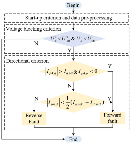
Figure 4.
Principle for detecting fault direction during symmetric faults.
When the fault type is determined to be a three-phase short circuit and the positive sequence voltage at the PCC drops below 0.9 p.u., the direction criterion based on the reactive current will be activated. First, detect the amplitude of the reactive current flowing through the protection device. If the amplitude of the reactive current is less than the set value, activate the active current amplitude criterion. If the amplitude of the reactive current is greater than the setting value, then determine its positive or negative sign. If the sign is negative, it is determined to be a reverse fault; if the sign is positive, activate the active current amplitude criterion. After entering the active current amplitude criterion, if the amplitude of the active current is greater than the set value, it is determined to be a fault in the reverse area; otherwise, it is determined to be a fault in the forward area.
4. Simulation Analysis
4.1. Simulation Tests for Asymmetrical Phase-to-Phase Faults
4.1.1. Operating Performance of the Voltage Blocking Criterion Under Asymmetric Phase-to-Phase Faults
In order to test the operation performance of the voltage blocking criterion, two-phase short-circuit faults are set at the end of line AB in the forward area and at the end of line CD in the reverse area, and the fault resistances are set to 0 Ω and 6 Ω, respectively. The simulation results are shown in Figure 5 and Figure 6. The negative sequence voltage is set to 0.2952 kV. Figure 5 shows that, in the case of metallic or high resistance two-phase short-circuit faults occurring at the ends of the forward and reverse areas, the negative sequence criterion can operate correctly. Figure 6 shows that, when a high resistance fault occurs at a remote location, the proposed direction criterion will be blocked.
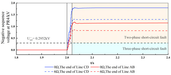
Figure 5.
Negative sequence voltage criterion action performance under asymmetric phase-to-phase faults in diverse fault conditions.
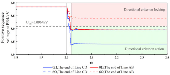
Figure 6.
Positive sequence voltage criterion action performance under asymmetric phase-to-phase faults in diverse fault conditions.
4.1.2. Operating Performance of the Negative Sequence Power Direction Criterion
In order to test the operating performance of the proposed negative sequence power direction criterion when the system operation mode changes, two-phase short-circuit faults are set at the midpoint of line segment AC in the forward area of PR4 and at the midpoint of line segment CD in the reverse area of PR4, with the fault resistance being 0.2 Ω. The influence of the system operation mode on the proposed direction criterion is compared. The simulation results are shown in Figure 7 and Figure 8.
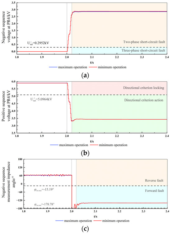
Figure 7.
Fault at line AC under different operating conditions (a) Positive sequence voltage at PR4. (b) Reactive current measured by PR4. (c) Negative sequence impedance angle measured by PR4.
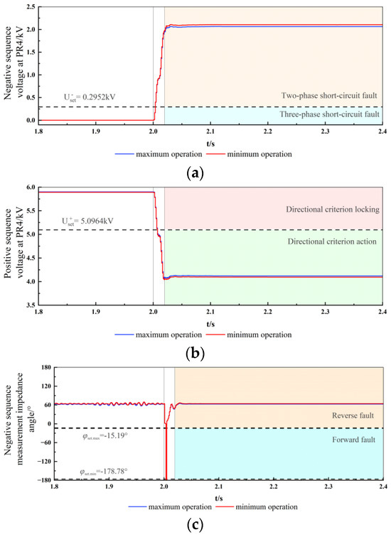
Figure 8.
Fault at line CD under different operating conditions. (a) Positive sequence voltage at PR4. (b) Reactive current measured by PR4. (c) Negative sequence impedance angle measured by PR4.
4.2. Simulation Tests for Symmetrical Faults
4.2.1. Operating Performance of the Voltage Blocking Criterion Under Symmetrical Faults
As can be seen from Figure 9, after the voltage criterion is activated, when high resistance and low resistance faults occur at the ends of the forward area and the reverse area of PR4, the negative sequence voltage criterion can accurately determine that the fault type is a three-phase short-circuit fault. As shown in Figure 10, when a high resistance fault occurs at a remote location, the proposed direction criterion will be blocked.
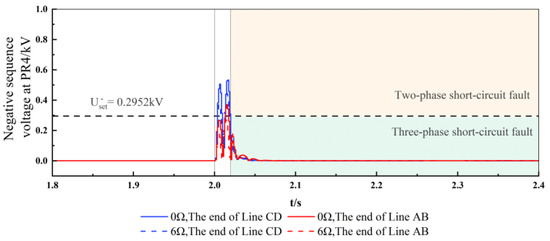
Figure 9.
Negative sequence voltage criterion action performance under symmetrical faults in diverse fault conditions.
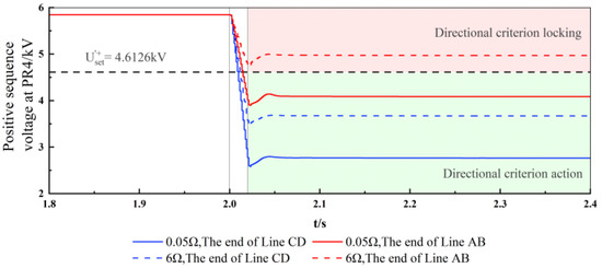
Figure 10.
Positive sequence voltage criterion action performance under symmetrical faults in diverse fault conditions.
4.2.2. Operating Performance of the Reactive Current Direction and Active Current Amplitude Direction Criteria
Three-phase short-circuit faults are respectively set at the exit of the reverse area of PR4 on line CD, at the midpoint of line CD in the reverse area, and at the midpoint of line AC in the forward area. The simulation results are shown in Figure 11, Figure 12 and Figure 13.
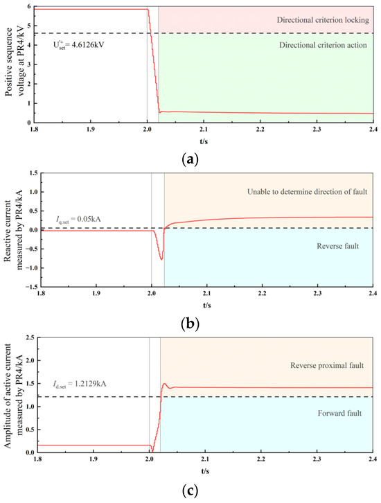
Figure 11.
Reverse proximal fault: Fault on line CD near bus C (a) Positive sequence voltage at PR4. (b) Reactive current measured by PR4. (c) Amplitude of active current measured by PR4.
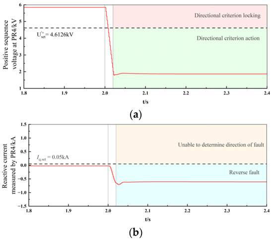
Figure 12.
Reverse fault: Fault at the midpoint of line CD (a) Positive sequence voltage at PR4. (b) Reactive current measured by PR4.
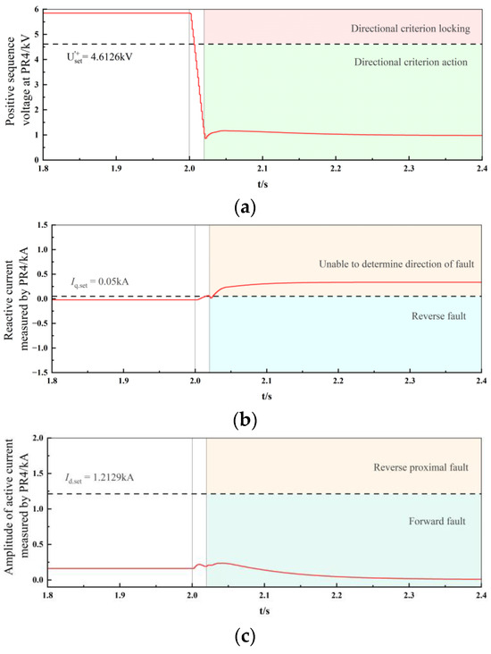
Figure 13.
Forward fault: Fault at the midpoint of line AC (a) Positive sequence voltage at PR4. (b) Reactive current measured by PR4. (c) Amplitude of active current measured by PR4.
Figure 11 shows that when a fault occurs in the proximal area of bus C on line CD, the voltage drops significantly, and the reactive current detected by PR4 is greater than 0. In this case, if only relying on the flow direction of the reactive current, it will be mistakenly judged as a forward fault. At this time, it is detected that the amplitude of the reactive current exceeds the set value and the sign is greater than 0, and the active current amplitude criterion is entered. At this moment, the active current flowing through PR4 is provided by the synchronous power source, and its amplitude is greater than the setting value, so it can be correctly judged as a reverse fault.
When a three-phase short-circuit fault occurs in the non-proximal area of the reverse line, such as at the midpoint of line CD, the simulation results are shown in Figure 12. In this case, the amplitude of the reactive current is greater than the set value, and the sign is negative. The reactive current criterion can correctly determine that a reverse fault has occurred, and there is no need to activate the active current amplitude criterion.
When a three-phase fault occurs at the midpoint of line AC in the forward area of PR4, the voltage criterion detects that the PCC voltage drops below 0.9 p.u., activating the reactive current direction criterion. At this time, the detected amplitude of the reactive current at PR4 is larger than the set value and the sign is positive. Since a positive sign cannot distinguish whether the fault is in the forward area or the reverse proximal area, the active current amplitude criterion is activated. Ultimately, the amplitude of the active current flowing through PR4 being less than the set value allows the fault to be correctly determined as a forward area fault.
5. Conclusions
This work analyzes the fault characteristics of distribution networks with PV and BESS. A protection principle for symmetrical and asymmetrical phase-to-phase faults is proposed, and the performance of the proposed principle is verified using simulation tests. The proposed protection principle operates correctly in selected typical fault scenarios. The main conclusions are as follows:
- (1)
- During asymmetric faults, the fault direction can be detected by utilizing the dynamic characteristics of the PV and BESS negative sequence impedance through monitoring negative sequence impedance angle at the protection relay location.
- (2)
- During symmetric faults, the fault direction can be identified by utilizing the characteristics of both PV and BESS/synchronous sources injecting reactive current and PV and BESS active current output being significantly lower than grid-side active current.
For the distribution network integrated with PV and BESS, this work proposes a fault detection principle applicable to symmetric faults and asymmetric phase-to-phase faults. However, other types of faults, such as single-phase short-circuit faults and two-phase-to-ground short-circuit faults, may also occur in distribution networks. In future work, protection principles suitable for single-phase short-circuit faults and two-phase-to-ground short-circuit faults in PV and BESS integrated distribution networks will be further investigated.
Author Contributions
Conceptualization, J.H. and L.L.; methodology, L.L.; software, J.N.; validation, Y.L., H.L. and Z.Y.; formal analysis, H.L.; investigation, Y.L.; resources, J.N.; data curation, Z.Y.; writing—original draft preparation, Z.Z.; writing—review and editing, Z.Z.; visualization, Z.Z.; supervision, C.L.; project administration, C.L.; funding acquisition, J.H. All authors have read and agreed to the published version of the manuscript.
Funding
This research was funded by the Ningxia Natural Science Foundation grant number [2023 AAC03838] and The APC was funded by the Ningxia Natural Science Foundation.
Institutional Review Board Statement
Not applicable.
Informed Consent Statement
Not applicable.
Data Availability Statement
All data included in this study are available upon request by contact with the corresponding author.
Acknowledgments
This work is supported by the project funded by the Ningxia Natural Science Foundation (2023 AAC03838).
Conflicts of Interest
Authors Jianan He, Lei Li, Jian Niu, Yabo Liang and Haitao Liu were employed by the company State Grid Ningxia Electric Power Co. Ltd. The remaining authors declare that the research was conducted in the absence of any commercial or financial relationships that could be construed as a potential conflict of interest.
References
- Zhang, Z.; Dou, C.; Yue, D.; Zhang, Y.; Zhang, B.; Li, B. Regional Coordinated Voltage Regulation in Active Distribution Networks With PV-BESS. IEEE Trans. Circuits Syst. II Express Briefs 2023, 70, 596–600. [Google Scholar] [CrossRef]
- Ould Amrouche, S.; Rekioua, D.; Rekioua, T.; Bacha, S. Overview of energy storage in renewable energy systems. Int. J. Hydrogen Energy 2016, 41, 20914–20927. [Google Scholar] [CrossRef]
- Zhang, Y.; Ma, T.; Yang, H. A review on capacity sizing and operation strategy of grid-connected photovoltaic battery systems. Energy Built Environ. 2024, 5, 500–516. [Google Scholar] [CrossRef]
- Yang, Y.; Li, H.; Aichhorn, A.; Zheng, J.; Greenleaf, M. Sizing Strategy of Distributed Battery Storage System With High Penetration of Photovoltaic for Voltage Regulation and Peak Load Shaving. IEEE Trans. Smart Grid 2014, 5, 982–991. [Google Scholar] [CrossRef]
- Haddadi, A.; Zhao, M.; Kocar, I.; Karaagac, U.; Farantatos, E. Impact of Inverter-Based Resources on Negative Sequence Quantities-Based Protection Elements. IEEE Trans. Power Deliv. 2021, 36, 289–298. [Google Scholar] [CrossRef]
- Jia, K.; Yang, Z.; Fang, Y.; Bi, T.; Sumner, M. Influence of Inverter-Interfaced Renewable Energy Generators on Directional Relay and an Improved Scheme. IEEE Trans. Power Electron. 2019, 34, 99. [Google Scholar] [CrossRef]
- Liang, Y.; Yang, X.; Wang, Y.; Wang, Y.; Pan, C. Internal fault probability-based time domain differential protection applied to transmission lines connecting battery energy storage stations. J. Energy Storage 2022, 55, 105707. [Google Scholar] [CrossRef]
- The Hoang, T.; Tuan Tran, Q.; Besanger, Y. An advanced protection scheme for medium-voltage distribution networks containing low-voltage microgrids with high penetration of photovoltaic systems. Int. J. Electr. Power Energy Syst. 2022, 139, 107988. [Google Scholar] [CrossRef]
- Kebede, A.A.; Kalogiannis, T.; Van Mierlo, J.; Berecibar, M. A comprehensive review of stationary energy storage devices for large scale renewable energy sources grid integration. Renew. Sustain. Energy Rev. 2022, 159, 112213. [Google Scholar] [CrossRef]
- Zeraati, M.; Golshan, M.E.H.; Guerrero, J.M. Distributed Control of Battery Energy Storage Systems for Voltage Regulation in Distribution Networks With High PV Penetration. IEEE Trans. Smart Grid 2018, 9, 3582–3593. [Google Scholar] [CrossRef]
- Tang, M.; Gao, X. Grid-connected Control of Microgrid with Photovoltaic and Energy Storage Systems Under Unbalanced Grid Voltage Conditions. High Volt. Eng. 2019, 45, 1879–1888. [Google Scholar]
- Yang, Z.; Li, C.; Yang, H.; Shengwei, L.; Bin, L. A direction detection method for the phase-to-phase fault of the distribution networks with BESS. In Proceedings of the 4th Energy Conversion and Economics Annual Forum (ECE Forum 2024), Beijing, China; IET: London, UK, 2025. [Google Scholar]
- Berger, M.; Kocar, I.; Farantatos, E.; Haddadi, A. Dual Control Strategy for Grid-tied Battery Energy Storage Systems to Comply with Emerging Grid Codes and Fault Ride Through Requirements. J. Mod. Power Syst. Clean Energy 2022, 10, 977–988. [Google Scholar] [CrossRef]
- Berger, M.; Kocar, I.; Farantatos, E.; Haddadi, A. Modeling of Li-ion battery energy storage systems (BESSs) for grid fault analysis. Electr. Power Syst. Res. 2021, 196, 107160. [Google Scholar] [CrossRef]
- Jiao, Y.; Liang, X.; Jiang, C. Directional element action area calculation considering LVRT of grid-connected PV plant. Electr. Power Autom. Equip. 2017, 37, 20–24. [Google Scholar]
- Jia, K.; Gu, C.; Xuan, Z.; Li, L.; Lin, Y. Fault Characteristics Analysis and Line Protection Design Within a Large-Scale Photovoltaic Power Plant. IEEE Trans. Smart Grid 2018, 9, 4099–4108. [Google Scholar] [CrossRef]
- Lai, Q.; Zhang, Z.; Yin, X.; Lin, Y. A New Method of Fault Direction Identification for Different Types of Renewable Energy Source Integrations. IEEE Trans. Power Deliv. 2022, 37, 2932–2941. [Google Scholar] [CrossRef]
- Mu, R.; He, J.; Li, B.; Li, L.; Lin, Y. Direction criterion of two-phase short-circuit faults in distribution networks with photovoltaic based on negative sequence current amplitude. Autom. Electr. Power Syst. 2024, 48, 148–161. [Google Scholar]
- Hooshyar, A.; Iravani, R. A New Directional Element for Microgrid Protection. IEEE Trans. Smart Grid 2018, 9, 6862–6876. [Google Scholar] [CrossRef]
- Joshua, A.M.; Vittal, K.P. Protection schemes for a battery energy storage system based microgrid. Electr. Power Syst. Res. 2022, 204, 107701. [Google Scholar] [CrossRef]
- Rezaei, M.F.; Gandomkar, M.; Nikoukar, J. Multi-objective Function Optimization for Locating and Sizing of Renewable Energy Sources and Energy Storages in Radial Distribution Networks with Digital Directional Overcurrent Relays and Digital Dual-setting Directional Overcurrent Relays. J. Electr. Eng. Technol. 2022, 17, 2095–2105. [Google Scholar] [CrossRef]
- GB/T 34120-2023; Technical Requirements for Power Conversion System of Electrochemical Energy Storage System. Standards Press of China: Beijing, China, 2023.
Disclaimer/Publisher’s Note: The statements, opinions and data contained in all publications are solely those of the individual author(s) and contributor(s) and not of MDPI and/or the editor(s). MDPI and/or the editor(s) disclaim responsibility for any injury to people or property resulting from any ideas, methods, instructions or products referred to in the content. |
© 2025 by the authors. Licensee MDPI, Basel, Switzerland. This article is an open access article distributed under the terms and conditions of the Creative Commons Attribution (CC BY) license (https://creativecommons.org/licenses/by/4.0/).