Article

Biomechanical Optimization of Lumbar Fusion Cages with a Porous Design: A Finite Element Analysis

Ningbo Institute of Technology, Beihang University, 399 Kangda Road, Ningbo 315832, China
*
Author to whom correspondence should be addressed.
Appl. Sci. 2025, 15(10), 5384; https://doi.org/10.3390/app15105384
Submission received: 8 April 2025 / Revised: 8 May 2025 / Accepted: 9 May 2025 / Published: 12 May 2025
(This article belongs to the Special Issue Advances in Biomimetic Design and Materials)

Abstract

:
Lumbar interbody fusion (LIF) is a standard treatment for spinal instability, yet postoperative subsidence and adjacent segment degeneration (ASD) remain critical challenges. This study evaluates the biomechanical efficacy of personalized porous fusion cages—featuring Gyroid (G-Cage) and Voronoi (V-Cage) architectures—against classic (C-Cage) and personalized (P-Cage) designs, aiming to enhance stability and mitigate subsidence risks. A finite element model of the L3–L4 segment, derived from CT scans of a healthy male volunteer, was developed to simulate six motion modes (compression, rotation, flexion, extension, and left/right bending). Biomechanical parameters, including range of motion (ROM), cage stress, endplate stress, and displacement, were analyzed. The results demonstrated that the V-Cage exhibited superior performance, reducing ROM by 51% in extension, cage stress by 41.7% in compression, and endplate stress by 63.7% in right bending compared to the C-Cage. The porous designs (G-Cage, V-Cage) exhibited biomimetic stress distribution and minimized micromotion, which was attributed to their trabecular-like architectures. These findings highlight the Voronoi-based porous cage as a biomechanically optimized solution, offering enhanced stability and reduced subsidence risk when compared to classic implants. The study underscores the potential of patient-specific porous designs in advancing LIF outcomes, warranting further clinical validation to translate computational insights into practical applications.

1. Introduction

Lumbar interbody fusion (LIF) is a standard treatment for spinal instability due to degenerative disk disease and spinal deformities. The procedure involves a partial re-section of vertebral elements and soft tissues, followed by the insertion of an interbody fusion cage to restore intervertebral spacing, spinal height, and natural curvature [1]. A variety of surgical techniques, implant designs, and grafting materials are utilized to promote biomechanically robust intervertebral fusion, stabilizing degenerated spinal segments, correcting alignment, and relieving pressure on the spinal canal [2]. Specifically, LIF accesses the L2–L5 intervertebral region via the anatomical corridor between the psoas major muscle and the aorta/inferior vena cava, preserving the structural integrity of the lamina and paraspinal musculature [3]. The deployment of an oversized fusion cage facilitates indirect decompression of neural elements by supporting the intervertebral disk while maintaining the posterior spinal architecture [4].
Despite its clinical success, LIF and the associated implantation of fusion cages can precipitate unintended biomechanical consequences, including adjacent segment degeneration (ASD) and cage subsidence [5]. Subsidence, characterized by the sinking of the cage into the vertebral endplate, is a prevalent complication that diminishes fusion segment height, disrupts spinal curvature, and risks nerve compression. These effects can compromise patient recovery, leading to persistent lower back pain and neurological deficits [6]. Emerging research attributes subsidence to factors such as an incompatible elastic modulus and suboptimal cage geometry, highlighting the need for innovative design solutions. Accordingly, refining fusion cage properties—through material modifications and the integration of microporous architectures—has become a focal point of investigation [7]. The morphological configuration of fusion cages plays a pivotal role in their optimization [8]. Conventional designs prioritize parameters such as contact surface area, intervertebral height restoration, and fixation stability. However, these standardized cages often fail to accommodate the anatomical variability among patients, resulting in suboptimal biomechanical outcomes [9]. Recent advancements in implant design have leveraged principles from bionics and biomechanics to introduce personalized approaches, which are gaining traction in the field. For example, Kang et al. [10] engineered patient-specific multi-segment intervertebral implants tailored to individual spinal anatomies, achieving both safety and favorable clinical outcomes. Such customized designs enhance the conformity between the cage and vertebral endplates, optimize biomechanical performance, ensure even stress distribution across the vertebral interface, and improve load transmission underscoring the value of personalization in reducing postoperative complications.
Beyond shape customization, the incorporation of porous architectures into fusion cage design offers additional advantages. By modulating the geometric properties of pore structures, cage stiffness can be precisely adjusted to prevent stress shielding while providing conduits for bone ingrowth, nutrient diffusion, and enhanced implant stability [11]. Porous configurations also lower the elastic modulus, mitigating stress shielding effects that can impede bone remodeling [12]. Among these structures, the Gyroid (G) scaffold stands out for its biomimetic resemblance to human bone, featuring high interconnectivity and tunable geometric parameters. Adjustments to its form can yield mechanical properties akin to cortical or cancellous bone, positioning it as a leading candidate for skeletal implants [13]. Studies indicate that Gyroid lattices outperform traditional scaffolds in elastic modulus and yield strength [14]. Similarly, the Voronoi pattern—drawing inspiration from natural structures like giraffe skin and turtle shells replicates the anisotropic porosity and connectivity of trabecular bone [15]. Jiao et al. [16] reported that strategic regulation of structural irregularities in Voronoi designs can boost yield strength by up to 30% by minimizing stress concentrations and redirecting load pathways. Through parametric modeling, the Voronoi approach enables fine control over pore size, porosity, and shape, yielding complex structures that closely mirror the morphology and mechanics of natural trabeculae [17].
Despite these innovations, biomechanical evaluations of personalized porous fusion cages with diverse lattice designs remain scarce. The influence of varying structural configurations on subsidence risk post-implantation is yet to be fully elucidated. Finite element (FE) analysis emerges as a robust methodology to bridge this knowledge gap, offering a non-invasive means to simulate and compare implant performance. FE modeling allows for precise alterations to cage geometry, accurately capturing interactions between structures, and facilitating direct comparisons across experimental conditions while minimizing the confounding effects of material variability [18,19]. By forecasting biomechanical behavior, functional outcomes, and potential complications, FE analysis provides insights that are challenging to obtain through traditional in vitro experiments, overcoming limitations such as time constraints and parameter inflexibility [20].
Based on this, this study created a variety of lumbar intervertebral fusion device designs based on the intervertebral fusion devices required for L3–L4 lumbar intervertebral lesions through personalized design combined with Gyroid and Voronoi structural parametric modeling. The biomechanical properties of different fusion devices implanted in the upper and lower end plates of the L3–L4 intervertebral disk were compared based on finite element (FE) analysis, and the risk parameters related to intervertebral fusion device subsidence and adjacent segment degeneration were evaluated based on von Mises stress and displacement changes. These preliminary studies will provide guidance for the design of fusion cages and offer new ideas for solving the problem of fusion cage sinking.

2. Materials and Methods

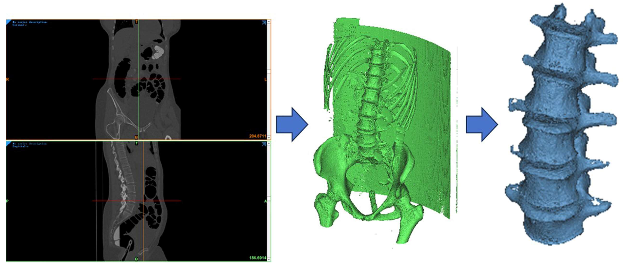
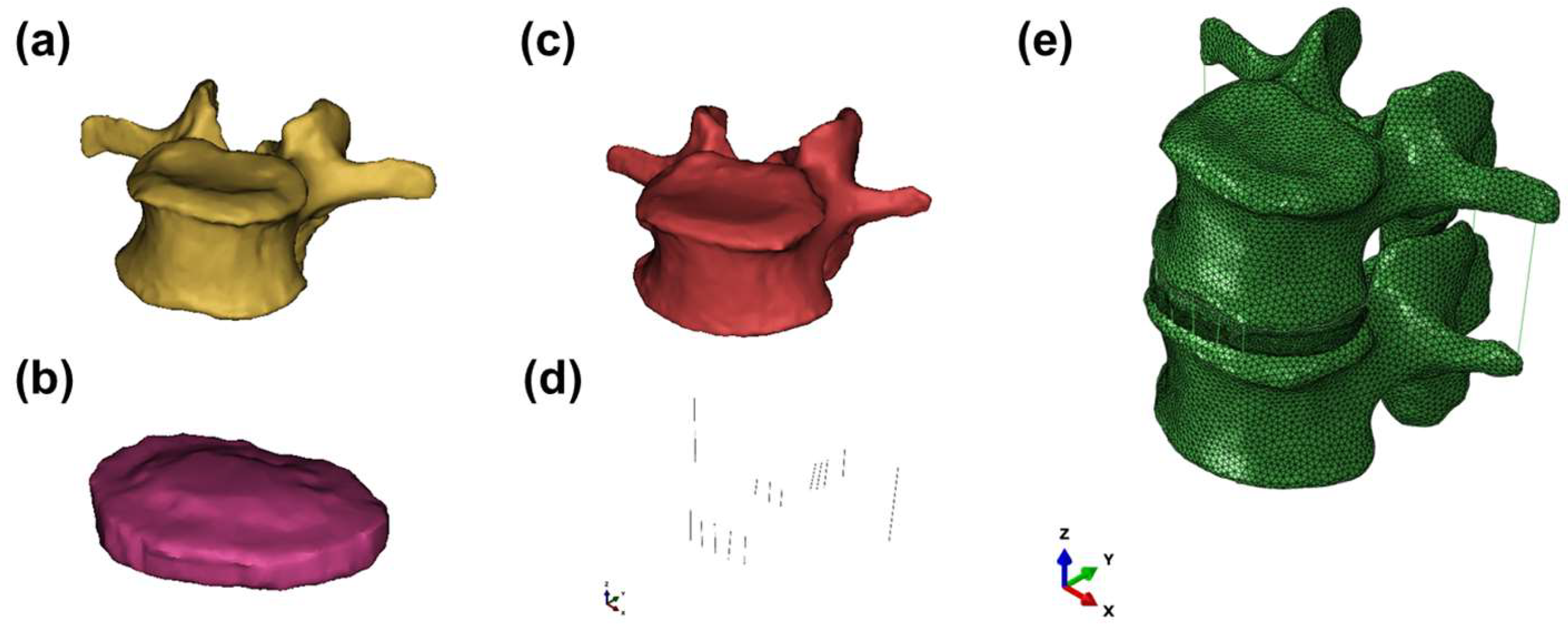
2.1. Development of the Lumbar Spine FE Model

The research object of this paper was a young and healthy male volunteer, aged 25 years old, 177 cm tall, 70 kg in weight, with no history of lumbar disease, and no deformity or degeneration of the lumbar spine was found in the X-ray examination. The study design based on volunteer was supported by Ethics Committee of First Affiliated Hospital of Ningbo University with informed consent obtained from the volunteer. The volunteer’s spine was scanned using a dual-source CT scanner from Siemens CT (scanning conditions: 120 kV, 125 mA, layer thickness: 0.8 mm, top-down spiral axial scanning), and a total of 609 DICOM images of the lumbar spine were extracted.
The L3–L4 lumbar segment was selected for this study due to its significant contribution to lumbar spine mobility and its frequent involvement in degenerative pathologies requiring fusion surgery, making it a clinically relevant and representative segment for comparing the biomechanical performance of different interbody cage designs. Focusing on a single segment allows for a clearer assessment of the cage design’s direct impact while minimizing confounding factors from multi-segmental interactions in this initial comparative analysis.
The CT data were processed in Mimics 21.0 (Materialise, Leuven, Belgium). Image denoising was performed, and optimal thresholds were established to distinguish bone from soft tissue boundaries. Soft tissue surrounding the vertebrae was removed based on the gray value in the range of 226–1672 Hu, followed by regional growth, smoothing, and gap-filling operations to produce a smooth, continuous vertebral outer contour. Cortical and cancellous bones were assigned using the gray value formula in Mimics, and intervertebral disks and cartilage were built in a preliminary three-dimensional model (Figure 1).
The model was exported in STL format to Geomagic Studio 2016 (Geomagic Inc., Cary, NA, USA) for refinement. Protrusions and depressions were eliminated, surfaces were smoothed, and triangular meshes were fitted to create a continuous surface model. Solid models of cortical bone, cancellous bone, intervertebral disks, and endplates were then constructed using SolidWorks 2016 (Dassault Systèmes, Paris, France), as shown in Figure 2.
The assembled solid model was imported into Abaqus 2020 (Dassault Systèmes, France) in IGES format for finite element analysis. In the L3–L4 segment, ligaments—including the anterior longitudinal, posterior longitudinal, supraspinous, interspinous, and intertransverse ligaments—were reconstructed. Material properties were assigned as follows: cortical bone, cancellous bone, and endplates were modeled as isotropic homogeneous elastic materials with thicknesses of 1.0 mm, 0.5 mm, and 0.5 mm (facet joint space), respectively.
Facet joint cartilage was set to 0.25 mm thick with a surface-to-surface contact and friction coefficient of 0.1. The nucleus pulposus was modeled as an incompressible fluid using fluid elements to simulate its hydrostatic behavior, constituting 45% of the intervertebral disk volume, while the annulus fibrosus was modeled with 8 layers of fibers oriented at ±30° to the transverse plane, comprising 55% of the intervertebral disk [21]. Ligaments, including the anterior longitudinal, posterior longitudinal, supraspinous, interspinous, and intertransverse ligaments, were modeled using nonlinear spring elements to simulate their physiological behavior (see Figure 2d) [22]. The finite element model of the L3–L4 single segment was generated using tetrahedral unit [23], convergence based on h-refinement with a 5% tolerance for stress and displacement, thus a total of 618,054 elements and 684,028 nodes, with an average mesh size of 0.1 mm. The properties of components in the lumbar spine model designed in this study were presented in Table 1.

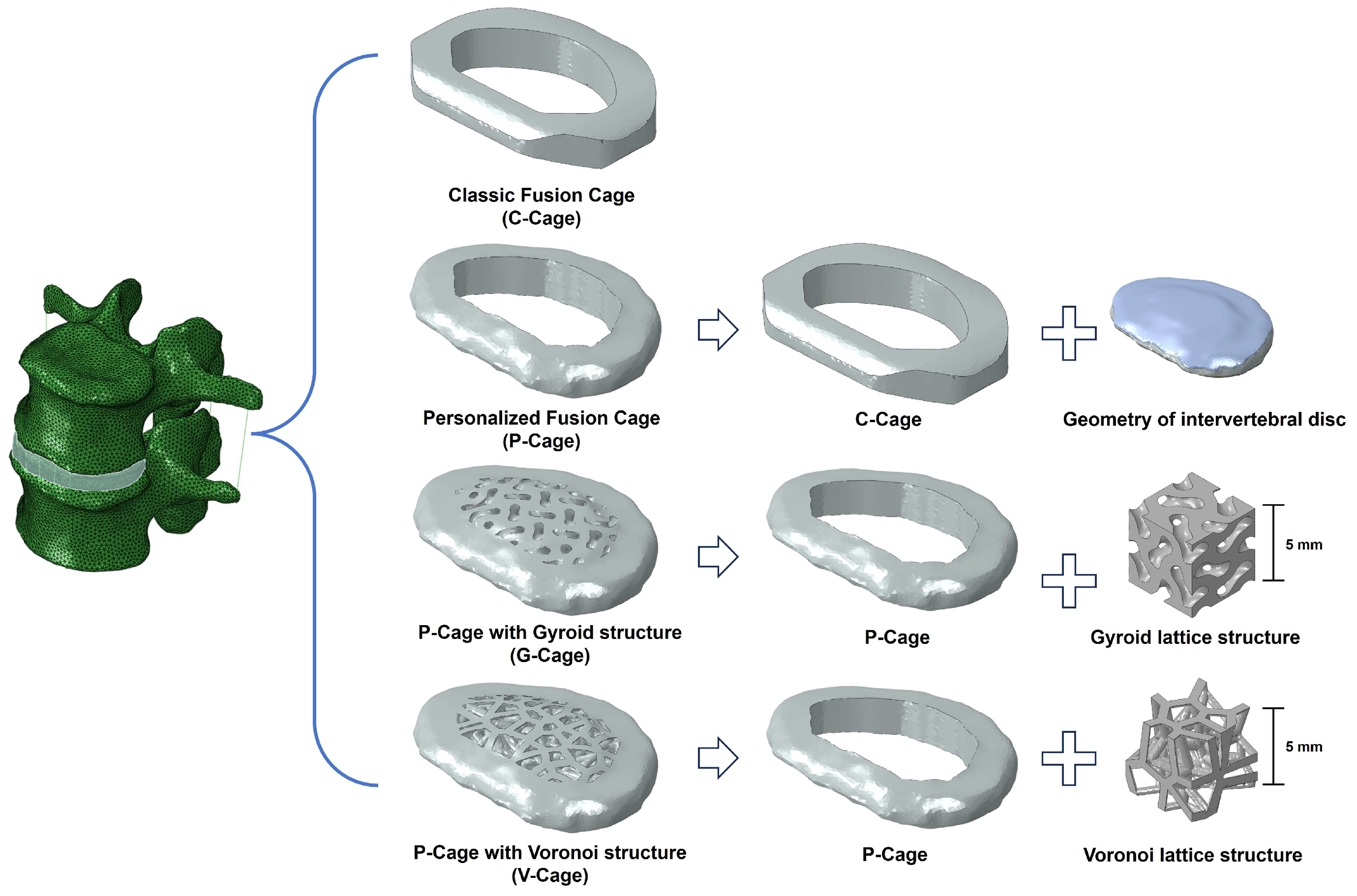
2.2. Design of Customized Lumbar Fusion Cage

The customized lumbar fusion cage was developed by adapting a standard classic cage model to incorporate biomimetic principles, ensuring compatibility with the anatomical features of the lumbar intervertebral space and vertebral bodies. The superior and inferior surfaces of the cage were manually contoured to precisely match the inferior endplate of L3 and the superior endplate of L4, ensuring optimal fit and stability. This precise customization enhances contact with the vertebral surfaces, improving stability and fit within the interbody space.
To achieve optimal biomechanical performance and biological integration, the cage design incorporated Gyroid and Voronoi lattice structures to mimic the trabecular bone’s anisotropic porosity and interconnectivity, enhancing mechanical stability and bone ingrowth. This biomimetic lattice was created using Gyroid and Voronoi parametric modeling techniques within Rhinoceros 6 (Robert McNeel & Associates, Seattle, WA, USA) and the Grasshopper plug-in (v.0.9.0076). For the detail modeling process, the region of interest based on the cage geometry was defined, and then distributed random seed points were established in the three-dimensional porous network (recorded in Table 2). After applying a scaling function with an adjustable scaling factor, the structure was refined into a mesh of pores and solid trabeculae, then the mesh was smoothed to form an interconnected lattice in order to mirror natural bone.
As can be seen from Figure 3, the final biomimetic trabecular porous cage was constructed by integrating the porous lattice with the solid cage geometry using Boolean operations. Target porosity and average pore size were optimized by adjusting the number of cell size (Gyroid) or seed distance (Voronoi), striking a balance between mechanical strength and bone in growth potential. This innovative design enhances both the structural integrity and biological functionality of the cage, positioning it as a promising solution for lumbar interbody fusion applications. All porous structures of G-Cage and V-Cage were developed with a similar relative density of 27% (porosity of 73%), and more details of the parameters used in the modeling are shown in Table 2.
All cage designs (C-Cage, P-Cage, G-Cage, and V-Cage) were assumed to be made of Magnesium alloy (Mg Alloy), a commonly used material for 3D-printed spinal implants due to its favorable biocompatibility and mechanical properties. For the finite element analysis, the material properties assigned to the cages were as follows: Young’s Modulus = 42,000 GPa and Poisson’s ratio = 0.31.

2.3. Boundary and Loading Conditions of the FE Model

The boundary conditions indicated degrees of freedom constraining the motion of all nodes for the lower surface of the L4 segment. To replicate physiological conditions, a vertical load of 400 N—approximating two-thirds of the body weight acting on the lumbar spine in an upright posture—was applied to the superior surface of L3 to simulate axial compression [29]. In addition, the torque of 10 N·m was also applied based on vertical load, to simulate axial rotation, flexion, extension, and lateral bending (left and right) by varying the torque direction [29]. The cage–bone interface was modeled with surface contact and a friction coefficient of 0.5 [30]. Contacts between vertebral bodies, intervertebral disks, and endplates were defined as tied, while facet joint contacts were set as sliding.

3. Results

3.1. Validation of the Intact Lumbar Spine Model

In this study, the finite element model of the segment (L3–L4) has a total of 618,054 units and 684,028 nodes. We compared the ROM measurement results of the finite element model with those of the literature and listed in Table 3. It was found that the results were basically within the variation range. This proved the effectiveness and robustness of the model and can be applied to the next step of lumbar biomechanical analysis.

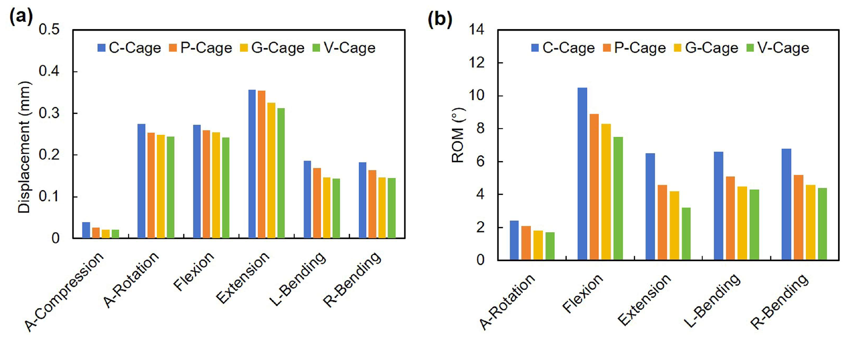
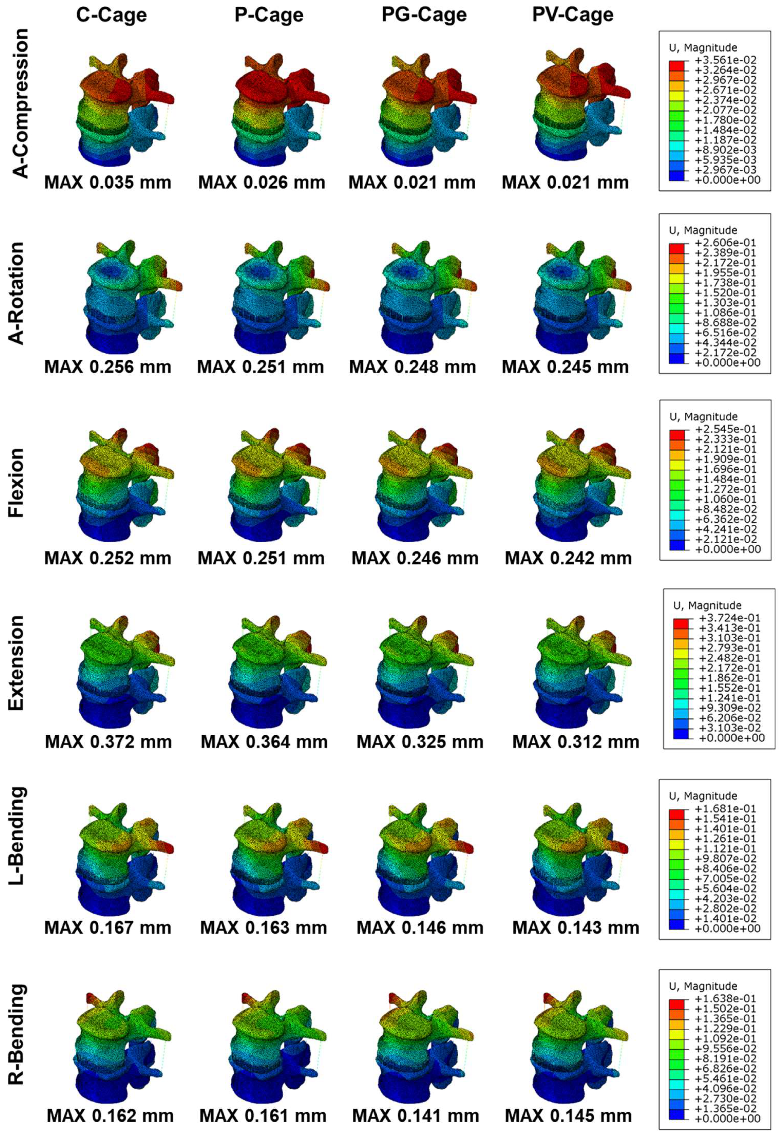
3.2. Stability of Endplates

The stability of the endplates following implantation of lumbar interbody fusion cages was evaluated through the range of motion (ROM) and displacement of the L3–L4 segment under motion conditions of axial compression (A-Compression), axial rotation (A-Rotation), flexion, extension, left bending (L-Bending), and right bending (R-Bending). These biomechanical parameters are essential for assessing the ability of fusion cages to maintain spinal stability and reduce the risk of subsidence. The results of displacement and ROM are detailed in Tables S1 and S2, respectively, and visually represented in Figure 4 and Figure 5, comparing the performance of four cage designs: C-Cage, P-Cage, G-Cage, and V-Cage.
The stability of the endplates was evaluated through the range of motion (ROM) based on simulated displacement of the L3–L4 segment. These displacement values, obtained from the finite element simulation output, serve as indicators to evaluate potential micromotion at the cage–endplate interface and subsequent subsidence risks. According to Figure 4a and Figure 5, the C-Cage exhibited the largest displacements across all load conditions, suggesting heightened susceptibility to interfacial micromotion and subsidence. While a slight decrease in displacement was observed for P-Cage with a value of 0.026 mm, 0.251 mm, 0.251 mm, 0.364 mm, 0.163 mm, and 0.161 mm, for A-Compression, A-Rotation, flexion, extension, L-bending, and R-Bending, respectively. Remarkably, both G-Cage and V-Cage were found to demonstrate exceptional performance, a decline of 16% in extension displacement was reported for the V-Cage when compared to the C-Cage. The porous architectures facilitated uniform stress distribution across the endplate interface, effectively suppressing micromotion and lowering subsidence propensity.
Range of motion (ROM) serves as a critical indicator for evaluating spinal kinematic stability, reflecting the ability of interbody fusion cages to constrain segmental motion and their impact on fusion efficacy and subsidence risks. In this study, ROM values were measured for the L3–L4 segment across five motion directions. According to Figure 4b and Table S2, the C-Cage exhibited the highest ROM values of 2.4°, 10.5°, 6.5°, 6.6°, and 6.8° for A-Rotation, flexion, extension, L-bending, and R-bending, respectively, indicating insufficient motion control and potential postoperative instability risks. The P-Cage with personalized morphology achieved marginal ROM reduction through optimized endplate congruency, though its efficacy remained limited. In contrast, both Gyroid-based porous cage (G-Cage) and Voronoi-inspired porous cage (V-Cage) significantly enhanced stabilization. Notably, V-Cage demonstrated superior performance, reducing ROM values to 1.7°, 7.5°, and 3.2° in a-rotation, flexion, and extension directions, respectively, representing reductions of approximately 29%, 29%, and 51% compared to C-Cage. The biomimetic Voronoi architecture effectively improved load distribution and spinal kinematic stability.

3.3. Cage Stress

The maximum von Mises stress within the cages was quantified across six motion modes as well as displacement of L3–L4 segment simulation, as visualized in Figure 6a and details in Table S3. The classic fusion cage (C-Cage) exhibited the highest stress levels across all loading conditions, with values ranging from 18.14 MPa in A-Compression to a peak of 63.04 MPa in flexion, indicative of the substantial mechanical demand placed on its structure. In contrast, the personalized P-Cage demonstrated a moderate reduction in stress, with values decreasing to 13.08 MPa in A-Compression and 52.9 MPa in flexion, suggesting that personalization alone offers some biomechanical advantage. Further reductions were observed with the porous designs, where the G-Cage recorded stresses of 11.43 MPa in A-Compression and 49.09 MPa in flexion, and the V-Cage achieved the lowest values, at 10.58 MPa and 45.41 MPa, respectively. Compared to the C-Cage, the V-Cage reduced maximum stress by 41.7% in A-Compression and 28.0% in flexion, underscoring its superior load-bearing capacity.
Stress distribution contour maps (Figure 6b) revealed that the C-Cage experienced pronounced stress concentrations, particularly at the cage–endplate interface, which could predispose it to fatigue failure. Conversely, the V-Cage displayed a more uniform stress distribution across its surface, attributable to its Voronoi-inspired porous architecture, which enhances load transfer efficiency and mitigates stress peaks. The G-Cage, while also porous, exhibited intermediate stress levels and distribution patterns, suggesting that the Gyroid structure, though effective, is less optimal than the Voronoi design in minimizing stress concentrations.

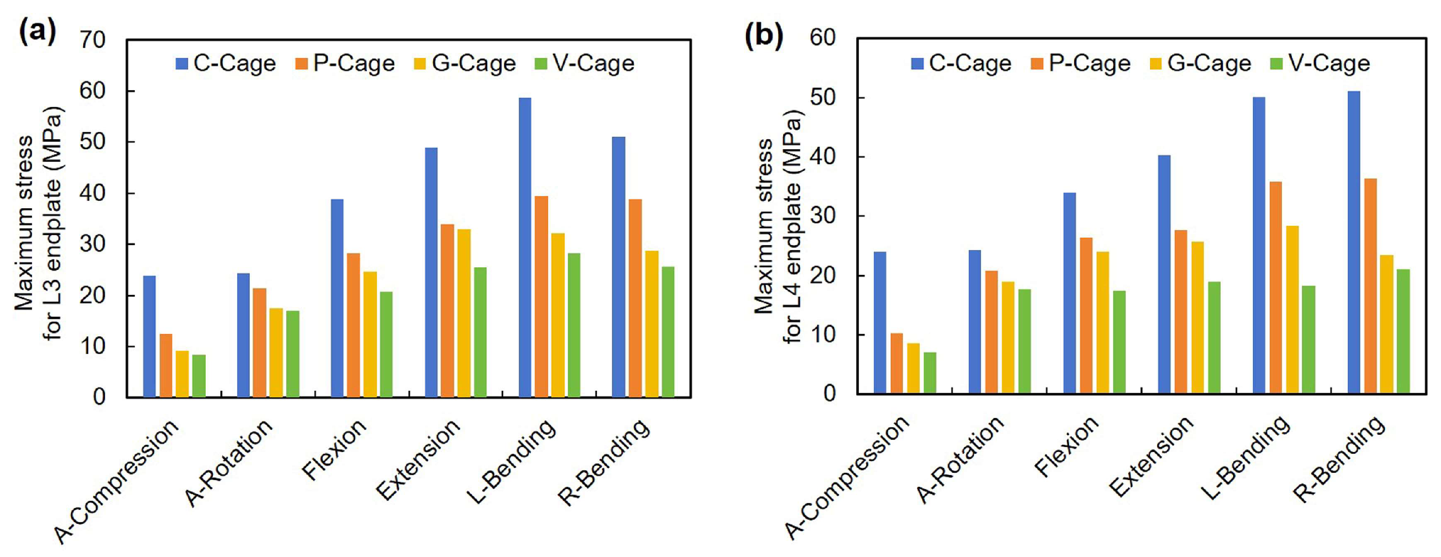
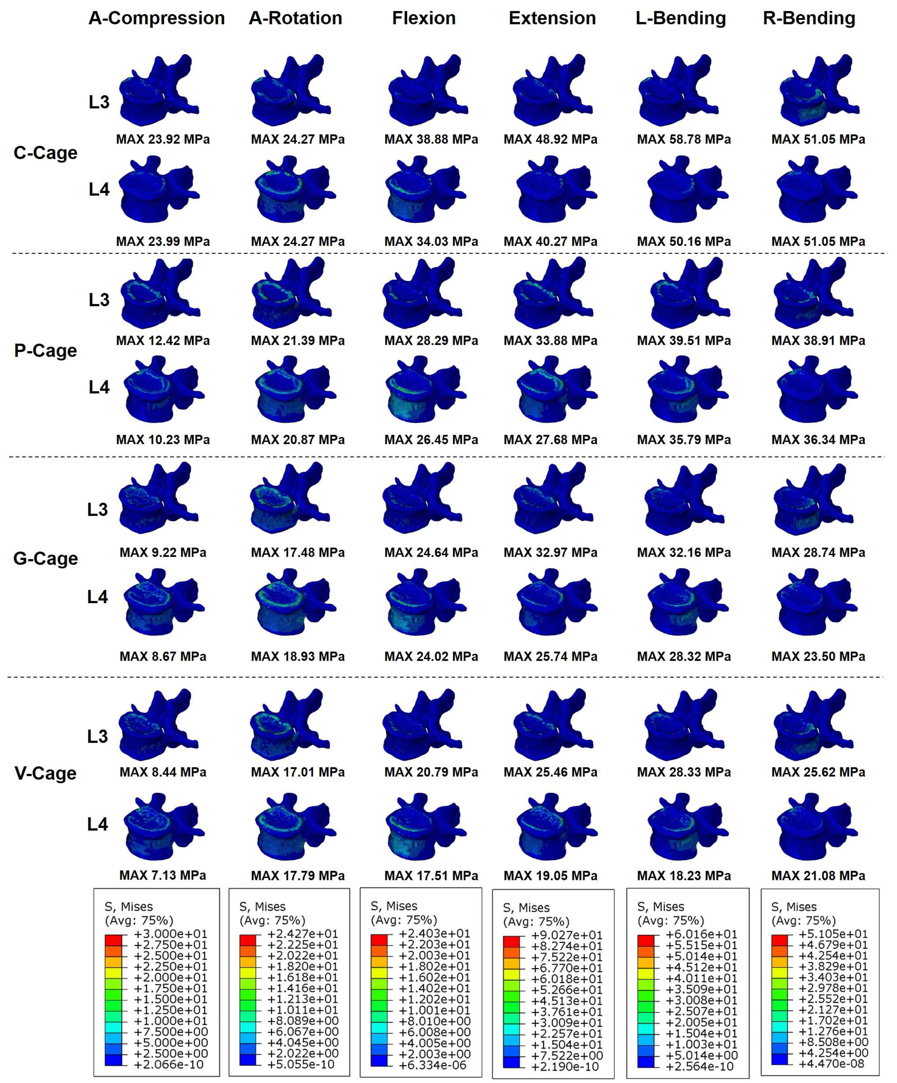
3.4. Endplate Stress

The maximum von Mises stress on the L3 and L4 endplates was evaluated under the same motion modes and the results were illustrated in Figure 7 and Figure 8, and the recorded data are listed in Table S4 and Table S5, respectively. For the L3 endplate, the C-Cage induced the highest stresses across all motion modes, peaking at 58.78 MPa in L-Bending and 51.05 MPa in R-Bending, reflecting significant mechanical loading that could compromise endplate integrity. The P-Cage reduced these values to 39.51 MPa and 38.91 MPa, respectively, indicating that personalized morphology mitigates stress to some extent. The G-Cage further lowered stresses to 32.16 MPa in L-Bending and 28.74 MPa in R-Bending, while the V-Cage achieved the most substantial reductions, with stresses of 28.33 MPa and 25.62 MPa, representing decreases of 51.8% and 49.8% compared to the C-Cage. A similar trend was observed for the L4 endplate, where the C-Cage recorded a maximum stress of 51.05 MPa in R-Bending and 50.16 MPa in L-Bending, contrasted by the values for the V-Cage of 21.08 MPa and 18.23 MPa, representing reductions of 58.7% and 63.7%, respectively.
Stress contour maps (as shown in Figure 8) highlight that the C-Cage generated localized high-stress zones on both endplates, particularly at contact points, increasing the risk of endplate failure and subsidence. In contrast, the V-Cage promoted a more even stress distribution, likely due to its biomimetic porous structure, which mirrors trabecular bone and optimizes load dissemination. The G-Cage and P-Cage exhibited intermediate stress profiles, with the former benefiting from its porous design and the latter from its tailored fit, though neither matched the efficacy of V-Cage. These findings suggest that the V-Cage not only withstands lower internal stresses but also significantly alleviates the mechanical burden on the endplates, a critical factor in preventing subsidence and enhancing fusion outcomes.

4. Discussion

The biomechanical performance of interbody fusion cages is fundamental to achieving postoperative spinal stability and minimizing subsidence risk. Our finite element (FE) analysis evaluated four distinct cage designs—C-Cage (classic), P-Cage (personalized), G-Cage (Gyroid), and V-Cage (Voronoi)—revealing that the Voronoi-based porous architecture offers superior mechanical and biological compatibility. These findings resonate with the growing emphasis on biomimetic and patient-specific implant designs, providing a framework to enhance clinical outcomes in lumbar interbody fusion.
Segmental stability, assessed via ROM, is a critical indicator of fusion success and long-term spinal health. The V-Cage exhibited the lowest ROM across all motion modes, including a 51% reduction in extension compared to the C-Cage. This enhanced stability arises from the interconnected pores of the Voronoi structure, which promote mechanical interlocking with the surrounding bone while retaining controlled flexibility. This behavior reflects the concept of “balanced stiffness” where porous implants stabilize spinal segments without imposing excessive rigidity, thus preserving physiological load transfer [34]. In contrast, the C-Cage and P-Cage displayed higher micromotion, which is associated with delayed fusion and pseudarthrosis [30]. These findings align with clinical evidence that overly rigid implants may accelerate adjacent segment disease (ASD) by disrupting spinal kinematics, reinforcing the biomechanical advantages of porous designs in maintaining segmental harmony [35].
The V-Cage, inspired by the anisotropic trabecular architecture of natural bone, exhibited exceptional stress dispersion compared to its solid and Gyroid-based counterparts. Its Voronoi porous structure reduced peak von Mises stress by 41.7% in compression and 28.0% in flexion relative to the C-Cage. This improvement stems from the irregular pore geometry, which redistributes mechanical loads more uniformly, mitigating stress concentrations. Such behavior aligns with prior studies demonstrating that Voronoi lattices enhance yield strength by up to 30% over uniform porous designs by mimicking the stress transfer pathways of cancellous bone [36]. In contrast, the G-Cage, with its isotropic Gyroid scaffold, achieved intermediate stress reduction but lacked the anisotropic adaptability of the V-Cage, limiting its ability to fully replicate the mechanical properties of bone. These results underscore the critical role of biomimetic irregularity in optimizing porous cage design, a principle increasingly validated in additively manufactured implants [37]. Effective load distribution across the vertebral endplates is essential to prevent subsidence, a common complication in interbody fusion. The V-Cage significantly lowered endplate stresses, reducing peak values on the L3 and L4 endplates by 51.8% and 63.7%, respectively, under bending modes. This reduction is attributable to the Voronoi structure, which likely provides a larger effective contact area, leading to reduced localized pressure and minimizing the risk of endplate microfractures [38]. Conversely, the classic C-Cage induced pronounced stress concentrations at the cage–endplate interface, consistent with clinical reports linking solid implants to increased subsidence risk [39]. Although the P-Cage improved geometric fit through personalization, it failed to address the stiffness mismatch between the implant and bone, underscoring the limitations of solid designs [32]. The V-Cage’s integration of porosity and patient-specific geometry aligns with proposals for using porous materials (such as titanium alloys) that harmonize elastic moduli with native bone, reducing stress shielding and enhancing endplate stability [39].
The superior performance of the V-Cage highlights the transformative potential of parametric modeling and additive manufacturing in interbody fusion. Current classic cages often adopt a standardized approach, potentially overlooking individual variations in vertebral anatomy and bone quality [40]. By integrating patient-specific geometry with biomimetic porosity, as demonstrated here and in prior multi-segment implant studies, the V-Cage optimizes both load-bearing capacity and osseointegration. Future advancements could leverage bioactive coatings or degradable materials such as bioresorbable magnesium alloy to further enhance osteoconductivity and implant longevity [41]. Such innovations could pave the way for fully personalized spinal implants tailored to individual biomechanical and biological profiles.
Due to the complex structure of the lumbar spine, the establishment of the finite element model and the corresponding analysis have certain limitations and can only reflect some movement patterns and biomechanical changes. The FE model was based on the L3–L4 segment of a single, healthy young male volunteer. This idealized model does not account for patient-specific variations or pathological conditions commonly encountered in clinical practice, such as degenerative disk disease, osteoporosis, or deformities. In unhealthy spines, factors like reduced bone mineral density, altered disk height, ligament laxity, and musculature could significantly influence cage stability, stress distribution, and subsidence risk, potentially leading to different biomechanical outcomes compared to those observed here. Therefore, the results should be interpreted as a comparative assessment under idealized conditions [42]. In addition, the simulation represented immediate postoperative conditions and did not capture long-term biological processes like bone ingrowth, remodeling, or implant fatigue [43]. Future studies are warranted to incorporate patient-specific pathological features (e.g., osteoporotic bone properties) and potentially multi-segmental models to provide a more comprehensive biomechanical evaluation relevant to diverse clinical scenarios. Despite these limitations, the current study provides valuable foundational insights into how personalized porous designs influence immediate postoperative biomechanics compared to traditional cages.
Nevertheless, the effectiveness of the finite element model in this experiment has been verified and has a certain predictive effect. Validation through in vitro mechanical testing and in vivo animal studies is essential to corroborate these computational predictions. Moreover, the manufacturing complexity and cost of Voronoi-based cages pose translational hurdles, reflecting broader challenges in scaling personalized implants for widespread clinical use [35]. In summary, this study delineates a clear hierarchy among interbody fusion cage designs, with the V-Cage emerging as the most biomechanically advantageous due to its Voronoi-based porous structure. By reducing stress concentrations, enhancing endplate stability, and optimizing segmental kinematics, this design offers a compelling foundation for improving fusion outcomes. These insights advocate for the continued exploration of porous, personalized implants to address the unmet needs of spinal surgery. Future studies should investigate how degenerative conditions, such as osteoporosis, might affect subsidence risk in pathological spine models.

5. Conclusions

This study utilized finite element analysis to evaluate the biomechanical performance of four lumbar interbody fusion cage designs (C-cage, P-cage, G-cage, and V-cage) in the L3–L4 spinal segment. The results demonstrated that the V-Cage, with its biomimetic Voronoi porous structure, outperforms other designs by significantly reducing the range of motion (51% in Extension), cage stress (41.7% in A-Compression), and endplate stress (63.7% in L-Bending) when compared to the C-Cage. These improvements were attributed to its ability to distribute mechanical loads uniformly, mimicking the anisotropic properties of natural trabecular bone, thereby enhancing spinal stability and minimizing subsidence risk. Additionally, the G-Cage also exhibited notable benefits over the control C-cage design, though it was less effective than the V-Cage due to its isotropic Gyroid structure. In contrast, the P-Cage, featuring personalization but lacking porosity, showed limited biomechanical advantages. These findings underscore the transformative potential of integrating patient-specific geometry with porous architectures in interbody fusion cages. As such, the V-Cage design investigated in this work offers a compelling alternative for potentially improving fusion outcomes and reducing postoperative complications, thus providing a foundation for advancing personalized, porous implant designs in spinal surgery.

Supplementary Materials

The following supporting information can be downloaded at: https://www.mdpi.com/article/10.3390/app15105384/s1, Table S1. Comparison of the displacement of the complete finite element model (mm); Table S2. Comparison of the ROM of the complete finite element model (Deg); Table S3. Maximum stress for cages of L3–L4 segment in six motion modes (MPa); Table S4. Maximum stress for L3 endplate with different cages in six motion modes (MPa); Table S5. Maximum stress for L4 endplate with different cages in six motion modes (MPa).

Author Contributions

Conceptualization, C.Z.; methodology, K.D.; software, K.D.; validation, Z.S.; formal analysis, Y.W.; investigation, C.Z.; resources, C.Z.; writing—original draft preparation, C.Z.; writing—review and editing, Z.S.; supervision, C.Z.; project administration, C.Z.; funding acquisition, C.Z. All authors have read and agreed to the published version of the manuscript.

Funding

This work was supported in part by Ningbo Key Projects of Science and Technology (No. 2023Z192).

Institutional Review Board Statement

The study was conducted in accordance with the Declaration of Helsinki, and approved by the Ethics Committee of First Affiliated Hospital of Ningbo University (Approval Number: 2024-05-1, Date: 5 June 2024).

Informed Consent Statement

Informed consent was obtained from all subjects involved in the study.

Data Availability Statement

Data available on request due to restrictions of privacy: the data presented in this study are available on request from the corresponding author.

Conflicts of Interest

The authors declare no conflicts of interest.

References

  1. de Kunder, S.L.; Rijkers, K.; Caelers, I.J.; de Bie, R.A.; Koehler, P.J.; van Santbrink, H. Lumbar interbody fusion: A historical overview and a future perspective. Spine 2018, 43, 1161–1168. [Google Scholar] [CrossRef] [PubMed]
  2. Schnake, K.; Rappert, D.; Storzer, B.; Schreyer, S.; Hilber, F.; Mehren, C. Lumbale spondylodese–indikationen und techniken. Orthopade 2019, 48, 50–58. [Google Scholar] [CrossRef] [PubMed]
  3. Taba, H.A.; Williams, S.K. Lateral lumbar interbody fusion. Neurosurg. Clin. 2020, 31, 33–42. [Google Scholar] [CrossRef] [PubMed]
  4. Olivares-Navarrete, R.; Gittens, R.A.; Schneider, J.M.; Hyzy, S.L.; Haithcock, D.A.; Ullrich, P.F.; Schwartz, Z.; Boyan, B.D. Osteoblasts exhibit a more differentiated phenotype and increased bone morphogenetic protein production on titanium alloy substrates than on poly-ether-ether-ketone. Spine J. 2012, 12, 265–272. [Google Scholar] [CrossRef]
  5. Du, C.-F.; Cai, X.-Y.; Gui, W.; Sun, M.-S.; Liu, Z.-X.; Liu, C.-J.; Zhang, C.-Q.; Huang, Y.-P. Does oblique lumbar interbody fusion promote adjacent degeneration in degenerative disc disease: A finite element analysis. Comput. Biol. Med. 2021, 128, 104122. [Google Scholar] [CrossRef]
  6. Yuan, W.; Kaliya-Perumal, A.-K.; Chou, S.M.; Oh, J.Y.-L. Does lumbar interbody cage size influence subsidence? A biomechanical study. Spine 2020, 45, 88–95. [Google Scholar] [CrossRef]
  7. Suh, P.B.; Puttlitz, C.; Lewis, C.; Bal, B.S.; McGilvray, K. The effect of cervical interbody cage morphology, material composition, and substrate density on cage subsidence. JAAOS-J. Am. Acad. Orthop. Surg. 2017, 25, 160–168. [Google Scholar] [CrossRef]
  8. Li, S.; Huan, Y.; Zhu, B.; Chen, H.; Tang, M.; Yan, Y.; Wang, C.; Ouyang, Z.; Li, X.; Xue, J. Research progress on the biological modifications of implant materials in 3D printed intervertebral fusion cages. J. Mater. Sci. Mater. Med. 2022, 33, 2. [Google Scholar] [CrossRef]
  9. Yu, Y.; Robinson, D.L.; Ackland, D.C.; Yang, Y.; Lee, P.V.S. Influence of the geometric and material properties of lumbar endplate on lumbar interbody fusion failure: A systematic review. J. Orthop. Surg. Res. 2022, 17, 224. [Google Scholar] [CrossRef]
  10. Kang, J.; Dong, E.; Li, X.; Guo, Z.; Shi, L.; Li, D.; Wang, L. Topological design and biomechanical evaluation for 3D printed multi-segment artificial vertebral implants. Mater. Sci. Eng. C 2021, 127, 112250. [Google Scholar] [CrossRef]
  11. Zadpoor, A.A. Mechanical performance of additively manufactured meta-biomaterials. Acta Biomater. 2019, 85, 41–59. [Google Scholar] [CrossRef] [PubMed]
  12. Al-Tamimi, A. 3D topology optimization and mesh dependency for redesigning locking compression plates aiming to reduce stress shielding. Int. J. Bioprinting 2021, 7, 339. [Google Scholar] [CrossRef] [PubMed]
  13. Ma, S.; Tang, Q.; Feng, Q.; Song, J.; Han, X.; Guo, F. Mechanical behaviours and mass transport properties of bone-mimicking scaffolds consisted of gyroid structures manufactured using selective laser melting. J. Mech. Behav. Biomed. 2019, 93, 158–169. [Google Scholar] [CrossRef]
  14. Zhang, L.; Feih, S.; Daynes, S.; Chang, S.; Wang, M.Y.; Wei, J.; Lu, W.F. Energy absorption characteristics of metallic triply periodic minimal surface sheet structures under compressive loading. Addit. Manuf. 2018, 23, 505–515. [Google Scholar] [CrossRef]
  15. Sotomayor, O.E.; Tippur, H.V. Role of cell regularity and relative density on elastoplastic compression response of 3-D open-cell foam core sandwich structure generated using Voronoi diagrams. Acta Mater. 2014, 78, 301–313. [Google Scholar] [CrossRef]
  16. Jiao, C.; Xie, D.; He, Z.; Liang, H.; Shen, L.; Yang, Y.; Tian, Z.; Wu, G.; Wang, C. Additive manufacturing of Bio-inspired ceramic bone Scaffolds: Structural Design, mechanical properties and biocompatibility. Mater. Des. 2022, 217, 110610. [Google Scholar] [CrossRef]
  17. Luo, L.; Li, J.; Lin, Z.; Cheng, X.; Wang, J.; Wang, Y.; Yang, Y.; Li, S.; Ling, Q.; Dai, J.; et al. Anisotropic biomimetic trabecular porous three-dimensional-printed Ti-6Al-4V cage for lumbar interbody fusion. Mater. Des. 2023, 233, 112254. [Google Scholar] [CrossRef]
  18. Jain, P.; Rana, M.; Biswas, J.K.; Khan, M.R. Biomechanics of spinal implants—A review. Biomed. Phys. Eng. Express 2020, 6, 042002. [Google Scholar] [CrossRef]
  19. Cai, X.Y.; Sun, M.S.; Huang, Y.P.; Liu, Z.X.; Liu, C.J.; Du, C.F.; Yang, Q. Biomechanical effect of L4–L5 intervertebral disc degeneration on the lower lumbar spine: A finite element study. Orthop. Surg. 2020, 12, 917–930. [Google Scholar] [CrossRef]
  20. Welch-Phillips, A.; Gibbons, D.; Ahern, D.P.; Butler, J.S. What is finite element analysis? Clin. Spine Surg. 2020, 33, 323–324. [Google Scholar] [CrossRef]
  21. Cai, X.-Y.; Bian, H.-M.; Chen, C.; Ma, X.-L.; Yang, Q. Biomechanical study of oblique lumbar interbody fusion (OLIF) augmented with different types of instrumentation: A finite element analysis. J. Orthop. Surg. Res. 2022, 17, 269. [Google Scholar] [CrossRef] [PubMed]
  22. Du, C.-F.; Yang, N.; Guo, J.-C.; Huang, Y.-P.; Zhang, C. Biomechanical response of lumbar facet joints under follower preload: A finite element study. BMC Musculoskelet. Dis. 2016, 17, 126. [Google Scholar] [CrossRef] [PubMed]
  23. Andrea, B.-F.; Elena, N.; Bentivoglio, D.; Aprato, A.; Terzini, M.; Bignardi, C.; Giaretta, S.; Momoli, A. In Silico Evaluation of the Primary Stability of Acetabular Revision Cups: Standard Versus Locking Screws. ASME J. Biomech. Eng. 2025, 147, 051007. [Google Scholar]
  24. Schmidt, H.; Heuer, F.; Simon, U.; Kettler, A.; Rohlmann, A.; Claes, L.; Wilke, H.-J. Application of a new calibration method for a three-dimensional finite element model of a human lumbar annulus fibrosus. Clin. Biomech. 2006, 21, 337–344. [Google Scholar] [CrossRef] [PubMed]
  25. Wu, T.-K.; Meng, Y.; Wang, B.-Y.; Rong, X.; Hong, Y.; Ding, C.; Chen, H.; Liu, H. Biomechanics following skip-level cervical disc arthroplasty versus skip-level cervical discectomy and fusion: A finite element-based study. BMC Musculoskelet. Dis. 2019, 20, 49. [Google Scholar] [CrossRef]
  26. Shirazi-Adl, S.A.; Shrivastava, S.C.; Ahmed, A.M. Stress analysis of the lumbar disc-body unit in compression a three-dimensional nonlinear finite element study. Spine 1984, 9, 120–134. [Google Scholar] [CrossRef]
  27. Goel, V.K.; Monroe, B.; Gilbertson, L.; Brinckmann, P. Interlaminar shear stresses and laminae separation in a disc: Finite element analysis of the L3-L4 motion segment subjected to axial compressive loads. Spine 1995, 20, 689–698. [Google Scholar] [CrossRef]
  28. Shirazi-Adl, A.; Ahmed, A.M.; Shrivastava, S.C. Mechanical response of a lumbar motion segment in axial torque alone and combined with compression. Spine 1986, 11, 914–927. [Google Scholar] [CrossRef]
  29. Ganbat, D.; Kim, Y.H.; Kim, K.; Jin, Y.J.; Park, W.M. Effect of mechanical loading on heterotopic ossification in cervical total disc replacement: A three-dimensional finite element analysis. Biomech. Model. Mechanobiol. 2016, 15, 1191–1199. [Google Scholar] [CrossRef]
  30. Lin, M.; Shapiro, S.Z.; Doulgeris, J.; Engeberg, E.D.; Tsai, C.-T.; Vrionis, F.D. Cage-screw and anterior plating combination reduces the risk of micromotion and subsidence in multilevel anterior cervical discectomy and fusion—A finite element study. Spine J. 2021, 21, 874–882. [Google Scholar] [CrossRef]
  31. Yamamoto, I.; Panjabi, M.M.; Crisco, T.; Oxland, T. Three-dimensional movements of the whole lumbar spine and lumbosacral joint. Spine 1989, 14, 1256–1260. [Google Scholar] [CrossRef] [PubMed]
  32. Xu, Z.; Zheng, Q.; Zhang, L.; Chen, R.; Li, Z.; Xu, W. Biomechanical evaluation of different oblique lumbar interbody fusion constructs: A finite element analysis. BMC Musculoskelet. Dis. 2024, 25, 97. [Google Scholar] [CrossRef] [PubMed]
  33. Nan, C.; Ma, Z.; Liu, Y.; Ma, L.; Li, J.; Zhang, W. Impact of cage position on biomechanical performance of stand-alone lateral lumbar interbody fusion: A finite element analysis. BMC Musculoskelet. Dis. 2022, 23, 920. [Google Scholar] [CrossRef] [PubMed]
  34. Zhang, H.; Fu, R.; Zhu, X. Multi-scale topology optimisation design and mechanical property analysis of porous interbody fusion cage. Bio-Med. Mater. Eng. 2024, 36, 110–123. [Google Scholar] [CrossRef]
  35. Talpeanu, G.; Awaja, F. Optimizing spinal fusion implants: Advanced biomaterials and technologies for improved outcomes. Biomed. Mater. Devices 2024, 1–33. [Google Scholar] [CrossRef]
  36. Han, C.; Wang, Y.; Wang, Z.; Dong, Z.; Li, K.; Song, C.; Cai, C.; Yan, X.; Yang, Y.; Wang, D. Enhancing mechanical properties of additively manufactured voronoi-based architected metamaterials via a lattice-inspired design strategy. Int. J. Mach. Tools Manuf. 2024, 202, 104199. [Google Scholar] [CrossRef]
  37. Kiselevskiy, M.V.; Anisimova, N.Y.; Kapustin, A.V.; Ryzhkin, A.A.; Kuznetsova, D.N.; Polyakova, V.V.; Enikeev, N.A. Development of bioactive scaffolds for orthopedic applications by designing additively manufactured titanium porous structures: A critical review. Biomimetics 2023, 8, 546. [Google Scholar] [CrossRef]
  38. Cheloni, J.P.M.; Zluhan, B.; Silveira, M.E.; Fonseca, E.B.; Valim, D.B.; Lopes, E.S. Mechanical behavior and failure mode of body-centered cubic, gyroid, diamond, and Voronoi functionally graded additively manufactured biomedical lattice structures. J. Mech. Behav. Biomed. 2025, 163, 106796. [Google Scholar] [CrossRef]
  39. Zhang, Z.; Li, H.; Fogel, G.R.; Xiang, D.; Liao, Z.; Liu, W. Finite element model predicts the biomechanical performance of transforaminal lumbar interbody fusion with various porous additive manufactured cages. Comput. Biol. Med. 2018, 95, 167–174. [Google Scholar] [CrossRef]
  40. Logroscino, G.; Proietti, L.; Pola, E. Spine fusion: Cages, plates and bone substitutes. In Biomaterials for Spinal Surgery; Elsevier: Amsterdam, The Netherlands, 2012; pp. 265–294. [Google Scholar]
  41. Cheers, G.M.; Weimer, L.P.; Neuerburg, C.; Arnholdt, J.; Gilbert, F.; Thorwächter, C.; Holzapfel, B.M.; Mayer-Wagner, S.; Laubach, M. Advances in implants and bone graft types for lumbar spinal fusion surgery. Biomater. Sci.-UK 2024, 12, 4875–4902. [Google Scholar] [CrossRef]
  42. Reisener, M.-J.; Pumberger, M.; Shue, J.; Girardi, F.P.; Hughes, A.P. Trends in lumbar spinal fusion—A literature review. J. Spine Surg. 2020, 6, 752–761. [Google Scholar] [CrossRef]
  43. Shah, A.A.; Devana, S.K.; Lee, C.; Bugarin, A.; Lord, E.L.; Shamie, A.N.; Park, D.Y.; van der Schaar, M.; SooHoo, N.F. Prediction of major complications and readmission after lumbar spinal fusion: A machine learning–driven approach. World Neurosurg. 2021, 152, e227–e234. [Google Scholar] [CrossRef]
Figure 1. A complete 3D model of the lumbar spine preparing process, from skeletal structure CT data of the lumbar spine to the final smoothed model with a repaired surfaced.
Applsci 15 05384 g001
Figure 2. The constructed 3D model for finite element analysis. A 3D model of (a) L3 segment, (b) intervertebral disk, (c) L4 segment, (d) ligaments, and (e) final assembled single segment model for FE analysis.
Applsci 15 05384 g002
Figure 3. The work flow diagram of the lumbar fusion cage with different structure designs implanted into the spine model.
Applsci 15 05384 g003
Figure 4. (a) Displacement and (b) range of motion (ROM) comparison for the L3–L4 segment implanted with different cage in the five common directions of motion.
Applsci 15 05384 g004
Figure 5. Simulation plots of displacement of the L3–L4 segment model implanted with the fusion cage under six different motion condition.
Applsci 15 05384 g005
Figure 6. The comparison of the stress for cages on six motion modes (a) maximum stress and (b) stress distribution on the cage surface.
Applsci 15 05384 g006
Figure 7. The comparison of the maximum stress on endplates for (a) L3 and (b) L4 on six motion modes.
Applsci 15 05384 g007
Figure 8. The stress distribution on the endplates of L3 and L4 surface on six motion modes.
Applsci 15 05384 g008
Table 1. Properties of different components in the lumbar spine model [24,25,26,27,28].
ComponentsYoung’s Modulus (MPa)Poisson’s RatioCross-Section Area (mm2)
Cortical bone12,0000.3/
Cancellous bone1000.2/
Bone endplate5000.25/
Nucleus pulposus10.499/
Annulus fibrosus40.45/
Anterior longitudinal ligament (ALL)80.3549.1
Posterior longitudinal ligament (PLL)100.3522.2
Intertransverse ligaments (ITL)50.354
Interspinous ligament (ISL)50.3549.2
Supraspinal ligament (SSL)50.3570.3
Table 2. Parameters used in the development of the 3D models of the cage structures in this study.
Cage DesignCell SizeSeed DistancePorosity DetailPersonalized Design
C-Cage///N
P-Cage///Y
G-Cage2.5 mm/73.3%Y
V-Cage/3 mm73.5%Y
Table 3. Comparison of the ROM of the complete finite element model in the present study (Deg).
FlexionExtensionL-BendingR-BendingRotationRef.
9.44.35.55.32.2Yamamoto et al. [31]
8.74.15.25.32.0 Xu et al. [32]
7.83.85.55.52.0Nan et al. [33]
9.24.15.35.22.1Present study
Disclaimer/Publisher’s Note: The statements, opinions and data contained in all publications are solely those of the individual author(s) and contributor(s) and not of MDPI and/or the editor(s). MDPI and/or the editor(s) disclaim responsibility for any injury to people or property resulting from any ideas, methods, instructions or products referred to in the content.

