Article

Physical Adaptation of Articulated Robotic Arm into 3D Scanning System

by
Mirko Sokovic
1,
Dejan Bozic
2,
Dejan Lukic
2,
Mijodrag Milosevic
2,
Mario Sokac
2 and
Zeljko Santosi
2,*
1
University of Ljubljana, Kongresni trg 12, 1000 Ljubljana, Slovenia
2
Faculty of Technical Science, University of Novi Sad, Trg Dositeja Obradovica 6, 21000 Novi Sad, Serbia
*
Author to whom correspondence should be addressed.
Appl. Sci. 2025, 15(10), 5377; https://doi.org/10.3390/app15105377
Submission received: 21 February 2025 / Revised: 5 May 2025 / Accepted: 9 May 2025 / Published: 12 May 2025
(This article belongs to the Special Issue Cyber-Physical Systems for Smart Manufacturing)

Abstract

:
Robots and 3D scanning systems are essential in modern industrial production, enhancing quality control, reducing costs, and improving production efficiency. Such systems align with Industry 4.0 trends, incorporating the Internet of Things (IoT), Big Data, Cyber–Physical Systems, and Artificial Intelligence to drive innovation. This paper focuses on the physical adaptation of old or out-of-use articulated robot arms for new tasks such as manipulation with a handheld 3D scanner, with the goal of automated quality control. The adaptation was carried out using a methodology that features the application of several techniques such as 3D digitization (photogrammetry), reverse engineering and 3D modeling (SolidWorks), the CAD search engine (3Dfindit), and 3D printing (fused deposition modeling—FDM). Reconstructed 3D models were used to design connecting elements, such as gripper jaws. The final results show that it is possible to create a connecting element utilizing this approach with very little expenditure of resources and time.

1. Introduction

Industrial robots represent a crucial link for mass production within traditional industrial production [1]. Also, they can be found in almost every segment of modern industry, Industry 4.0 [2], the Internet of Things (IoT), Big Data (BD), and Cyber–Physical Systems [3,4], including Artificial Intelligence (AI), where data analytics, automation, and real-time monitoring are key factors [5,6]. Here, 3D digital models are an integral part of digital twins, enabling the simulation of real-world issues [7,8,9]. According to ISO 8373:2021 [10], an industrial robot is understood as an automatically controlled, reprogrammable, multipurpose manipulator, programmable in three or more axes, which can be either fixed in place or fixed to a mobile platform for use in an industry. Industrial robots can be divided into six types: Polar Coordinate, Cylindrical Coordinate, Cartesian Coordinate, Vertically Articulated, Selective Compliance Assembly Robot Arm (SCARA), and Parallel-Link Robots [11,12]. The widespread application of such robots is becoming economically justified across various fields, and it has been approved through numerous experiments and evaluations in scientific studies [1,13,14,15]. Robotic three-dimensional (3D) scanning systems are crucial in modern industrial production to maintain competitive advantage in industries by enhancing the quality control of products, enabling faster production times, and reducing operational costs [16,17,18,19].

Background

As the progress and development of robots are constantly advancing, upgrading existing robots is the key to sustainability. Boosting the existing robots using modern software frameworks is the first common solution. Outdated robotic systems can be revitalized by replacing their control systems with new ones that enhance motion planning capabilities and allow for much more sophisticated tasks [10]. Moreover, the integration of IoT facilitates remote control of a robot. This approach allows the control of a robotic arm from remote locations via a mobile application [20].
Old robotic arms can be used for basic educational purposes. Educational institutions can provide practical training on robots substituted in the industry by new ones. An articulated robotic arm can be involved in projects where students learn about programming, control systems, and sensors, improving the learning experience [21].
From an industry perspective, robotic arms can be adapted for specific tasks such as sorting, welding, or assembly [22]. Even older robotic arm models can be redesigned to achieve high performance in simple tasks [23]. The manufacturing industry has a desire to move from mass production to mass customization or personalized manufacturing. Therefore, there are several challenges with reconfigurable manufacturing systems (RMSs) due to their dynamic nature, where robots and other manufacturing machines can be moved and rearranged [24]. This approach promotes sustainability in robotics by encouraging the reuse of existing robots.
Automated robotic 3D scanning systems are a significant part of industrial quality control, especially in the metrology sector where 3D scanners capture 3D data and ensure precision and accuracy in production [25]. Considering the increasing use of free-form surfaces across various industries and the fact that worn parts with such surfaces are often no longer used, Ma et al. [26] proposed a method that utilizes a combination of a Linear Laser Scanner and a Laser Cladding Nozzle installed on an industrial robot. It allows worn free-form surface parts to be scanned, and based on the analyzed wear, damaged areas can be filled up and restored to their original state. Moreover, a vision-based method for positioning parts uses multi-camera images to reconstruct 3D point clouds and align them with the part’s computer-aided design (CAD) model, achieving high positioning accuracy and enhancing the robot’s flexibility in dynamic conditions [27]. In industry, robots are used to investigate the influence of cutting process parameters on the cutting forces and fabric quality of woven fibers during ultrasonic cutting [28]. Also, investigations of the application of industrial robots in the additive manufacturing of thermoplastics emphasize the benefits of free-form fabrication and the integration of fused deposition modeling (FDM) technology with robotic systems [29].
Thanks to grippers, robots are highly adaptable to new tasks, which is one of their key advantages. They can be classified into several categories based on their design and purpose. Traditional hard grippers, which often utilize rigid components, are effective for grasping well-defined objects’ geometry, but they may have difficulty interacting with irregularly shaped surfaces [30]. Moreover, soft robotic grippers offer more flexibility for the shape of the objects they grasp. They provide a gentler touch that is particularly beneficial for applications on fragile items [3]. These soft grippers are usually driven using pneumatic systems and cable-driven mechanisms, but nowadays, even shape memory alloys are used [31]. Using the principles of customization, robotic arms with appropriate executive parts and control systems can be tailored to the specific needs of a production line, thus maximizing its productivity.
Unlike previous research, this research focuses on solving connection issues between an articulated robotic arm and a handheld 3D scanner. Old robots have poor performance in comparison to new sophisticated robotic arms. Many of those robots often do not have a new purpose in the production process. They are usually stored and not used. But if they are adapted to carry a new executive body such as a handheld 3D scanner, they can be operated again for quality control. Handheld 3D scanners are not designed to be mounted on a robotic arm, and this is exactly the challenge in finding an adequate and simple solution to connecting them together. The proposed innovative approach involves several complex methods, including 3D digitization (photogrammetry), reverse engineering (RE) and 3D modeling (SolidWorks), CAD search engines (3Dfindit), and additive manufacturing (FDM 3D printing). The main research contributions are as follows:
  • Adaptation methodology approach for any robotic arm and handheld 3D scanner.
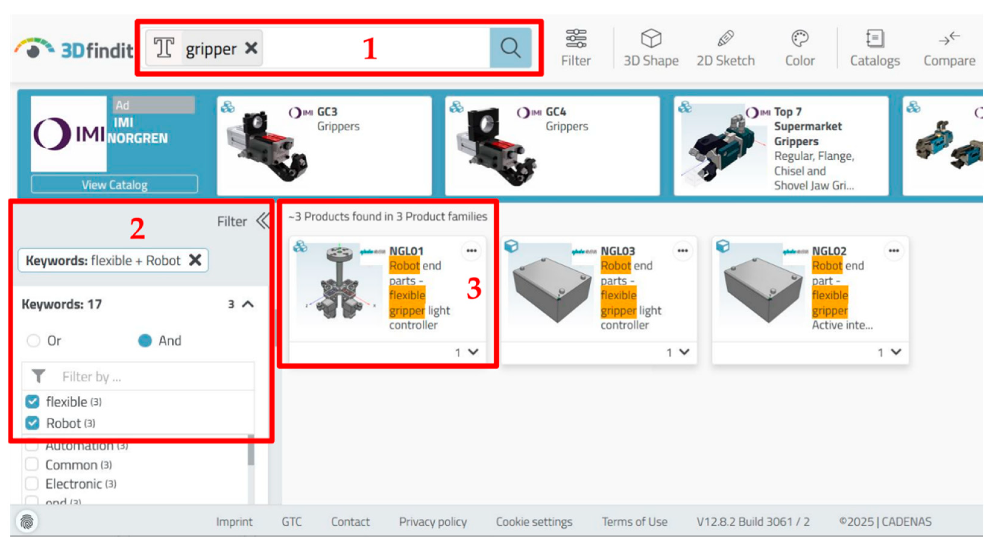
  • The application and use of a CAD search engine for searching existing commercial solutions for robotic grippers and other standard components.
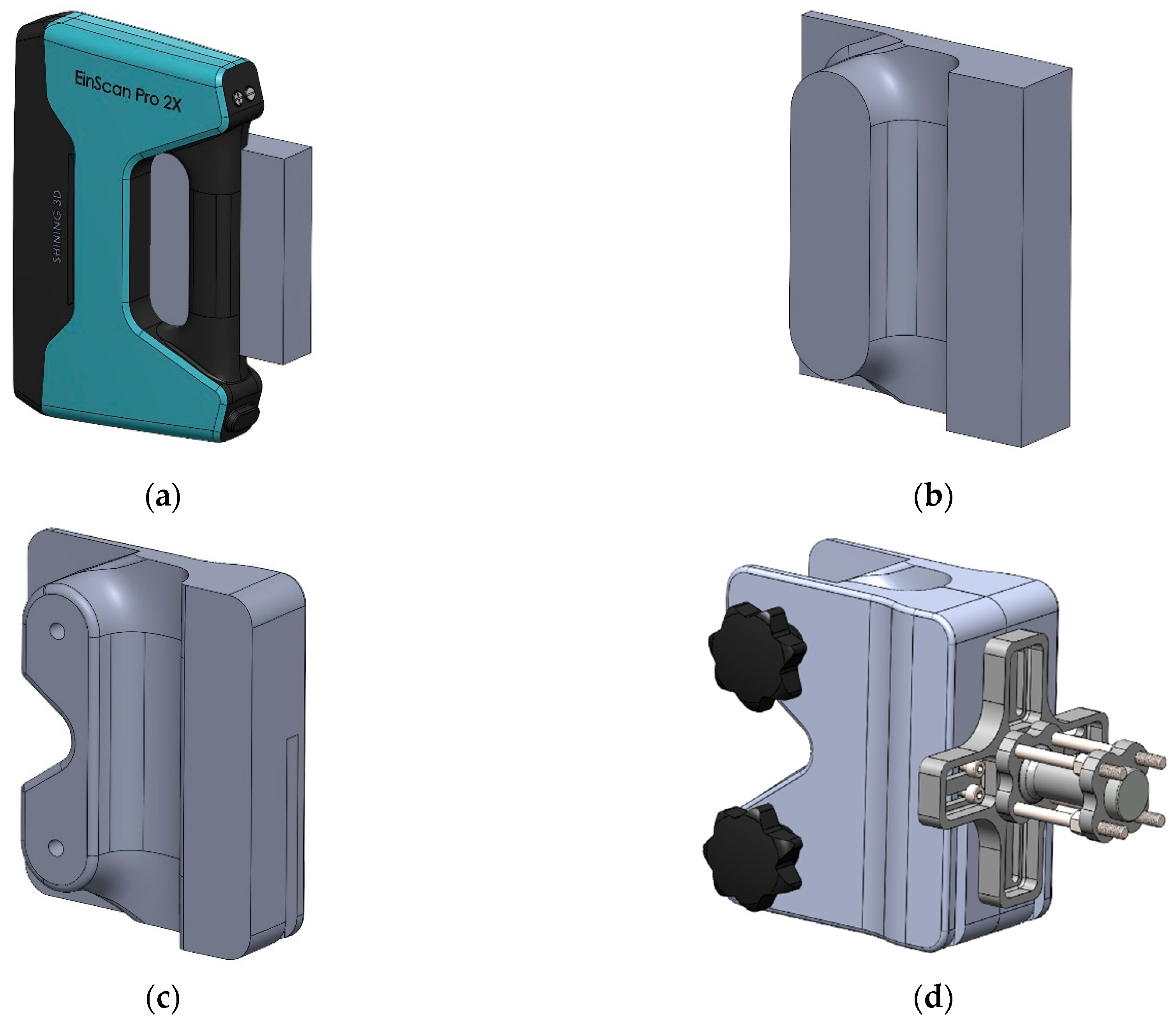
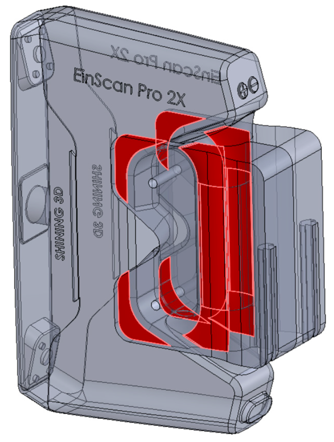
  • The development of a fully useable 3D-printed connection element that consists of gripper jaws and a gripper body.
  • Storing the designed 3D models on the 3Dfindit CAD search engine platform for free download and use.

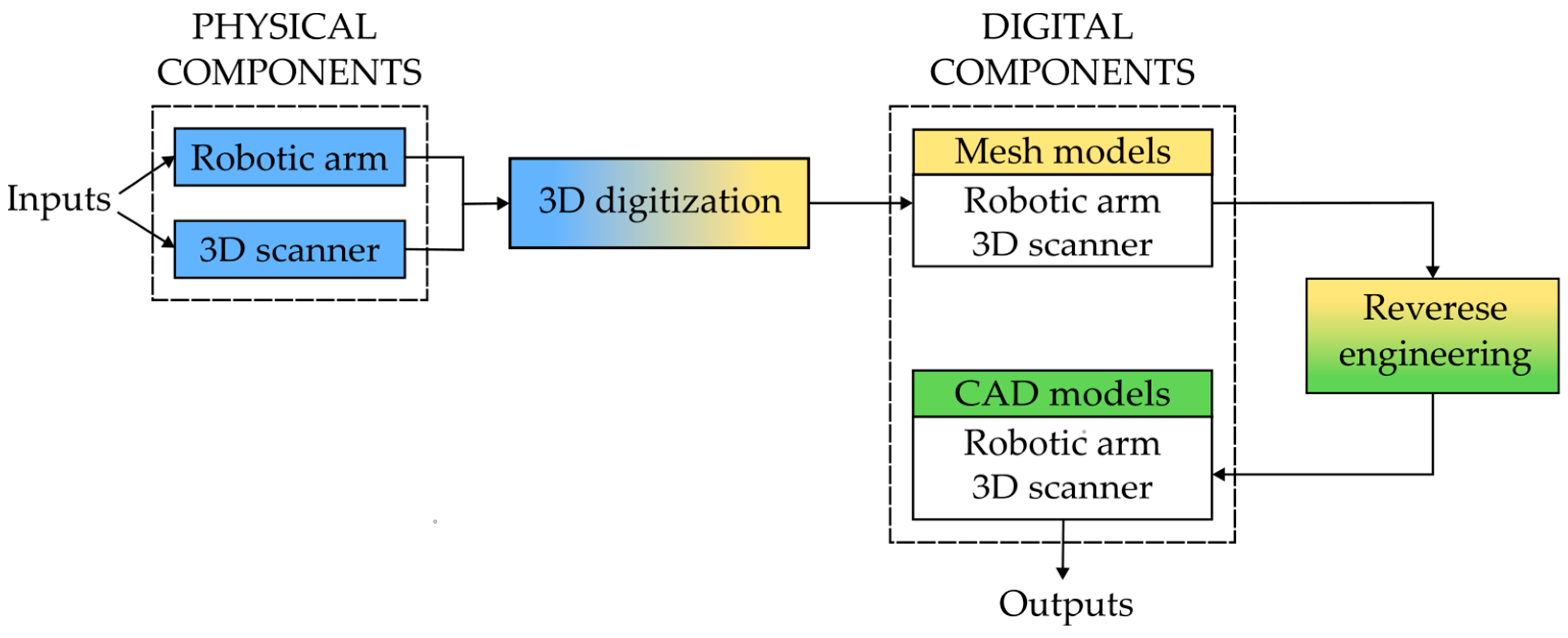
2. Materials and Methods

The adaptation methodology consists of two methods that contribute to the physical adaptation of a robotic arm into a 3D scanning system. This innovative approach solves the first issue of creating a 3D scanning system, which is the physical connection between the robotic arm and the handheld 3D scanner. Of course, there are closed solutions from large manufacturers who independently develop their own automated 3D scanning systems [32,33,34]. Figure 1 shows a workflow diagram of the digital transformation method, which refers to the input physical components and the creation of output digital components.
A robotic 3D scanning system comprises several integral components, with the two primary elements being an articulated robotic arm and a handheld 3D scanner. The second step represents the transition, i.e., the translation of physical components into digital ones through 3D digitization. Today, numerous 3D digitization methods have been developed that have certain possibilities when it pertains to translating physical components into digital ones. It is possible to divide them according to various criteria, such as the principle of operation, accuracy, range, and speed [35,36]. Choosing a 3D digitization method requires a complex engineering approach that includes many other additional influencing factors [37]. Based on the available equipment, the speed of 3D digitization, and the required accuracy, the photogrammetric method was chosen because only a digital camera is needed, it is suitable for 3D digitization of large (larger than 0.5 m) and small objects (less than 0.5 m), it does not require expensive equipment, and it uses free photo processing software. The disadvantages of this technique are reflected in the accuracy, ranging from 0.1 mm to approximately 0.5 mm (depending on the size of the object), compared to laser and structured light scanners, whose accuracy is around or below 0.04 mm. As a result of 3D digitization, a point cloud is obtained, which is subsequently transformed into a 3D polygonal mesh model. After that, an RE technique is applied. RE in mechanical engineering refers to the process of extracting knowledge or design information from existing products and available data. This practice is particularly valuable when original design documentation is unavailable, allowing the recreation of missing components. The essence of RE lies in its ability to generate a geometric 3D model from a physical object [38,39]. RE is used to convert scanned data (polygonal mesh models) into precise, editable CAD models. There are no instances where this was a limitation in the study. RE is preferred for providing more detailed 3D reconstructions than ordinary direct CAD modeling. Handheld 3D scanners are rich in complex surfaces that are consequences of ergonomic design. These complex surfaces can be easily reconstructed by RE.
Figure 2 shows a workflow diagram of the development of a fully useable 3D-printed connection element. Today, 3D models are available for downloading through online CAD search engine platforms, or directly from manufacturers. One of the free CAD search engines is 3Dfindit (CADENAS GmbH, Augsburg, Germany) [40], which represents the starting point in the gripper development workflow diagram (Figure 2). It offers free downloads of 3D models from thousands of verified manufacturer catalogs [41,42,43]. Query input can be in the form of text, photos, sketches, and existing CAD models [44]. 3Dfindit simplifies the search process by allowing filtration of the results based on specific criteria such as keywords, standards, file format, category, and manufacturer. If the given results do not satisfy expectations, it is always possible to run a new search. The work with a CAD search engine is carried out when the appropriate CAD model has been downloaded (Figure 2). This raises the question of whether geometric modifications are needed to meet the requirements of 3D printing while maintaining the functionality and strength of the gripper. These modifications typically involve increasing dimensions to optimize the strength and lightweight properties inherent to 3D printing [45,46].
If modification of the original gripper is not required or the modification process has been completed, it goes to the question, “Design verification?”. This step determines whether the gripper meets all the necessary geometric requirements to connect with the robotic arm. If the answer is “No”, the process returns to the question, “Modifications?”. This question is provided because commercial gripper jaws do not satisfy the requirements for clamping the handheld 3D scanner properly. Every handheld 3D scanner has a unique design, and gripper jaws must be adjusted to the shape of a 3D scanner. Also, commercial grippers are usually manufactured from stronger materials like metal, not plastic, which is dominant in 3D printing. In contrast, a verified gripper is considered ready for 3D printing and can be stored in a database.
Also, it can serve as the initial input for 3D modeling of the gripper jaw. Due to the specific geometric requirement for clamping the 3D scanner handle, it is necessary to 3D model the hard gripper jaws. The second input is the CAD model of the 3D scanner. Gripper jaws should be designed for easy handling, a firm grip, and 3D printing. After the 3D modeling stage, design verification is performed. If the design passes verification, the jaws are ready for 3D printing and storing in the platform database. If not, the design returns to the modeling stage for adjustments.

3. Results

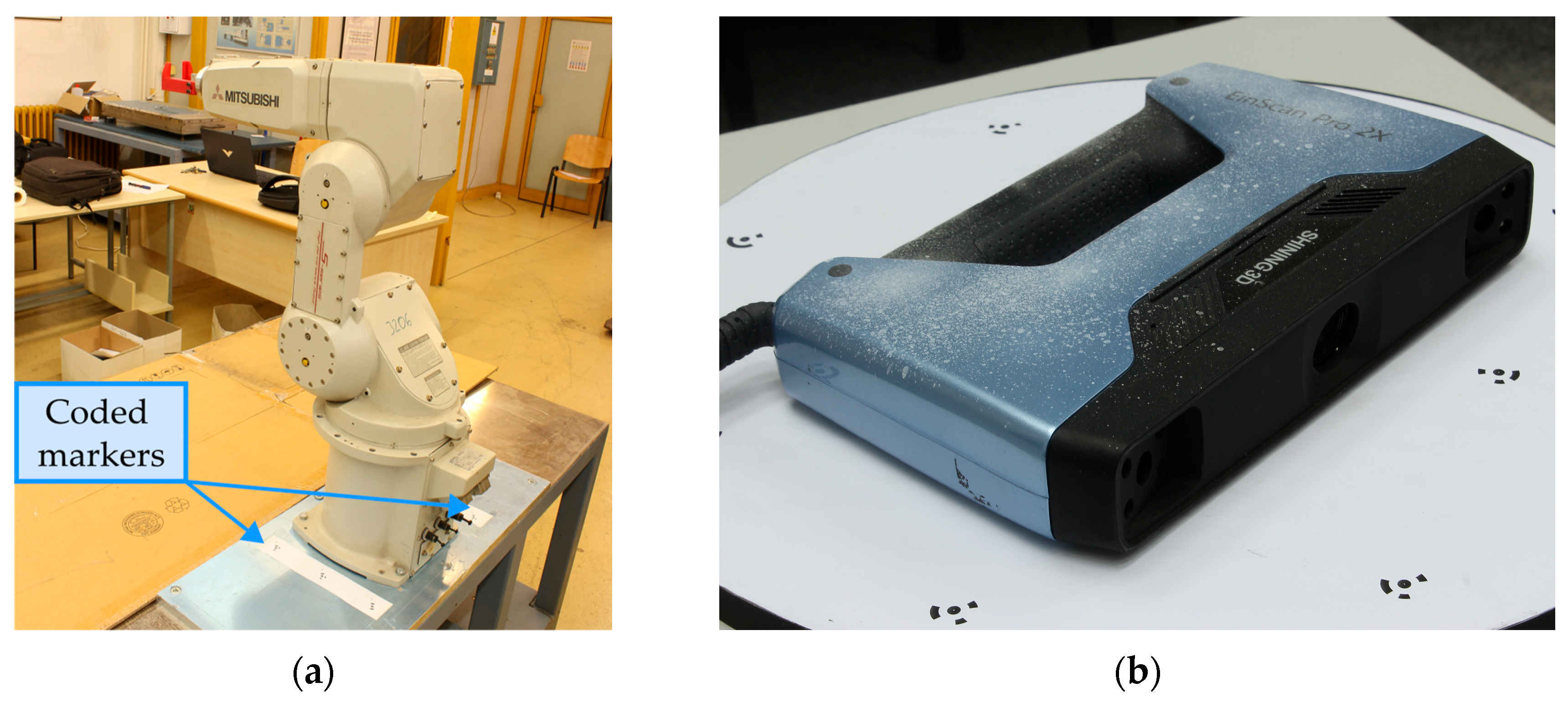
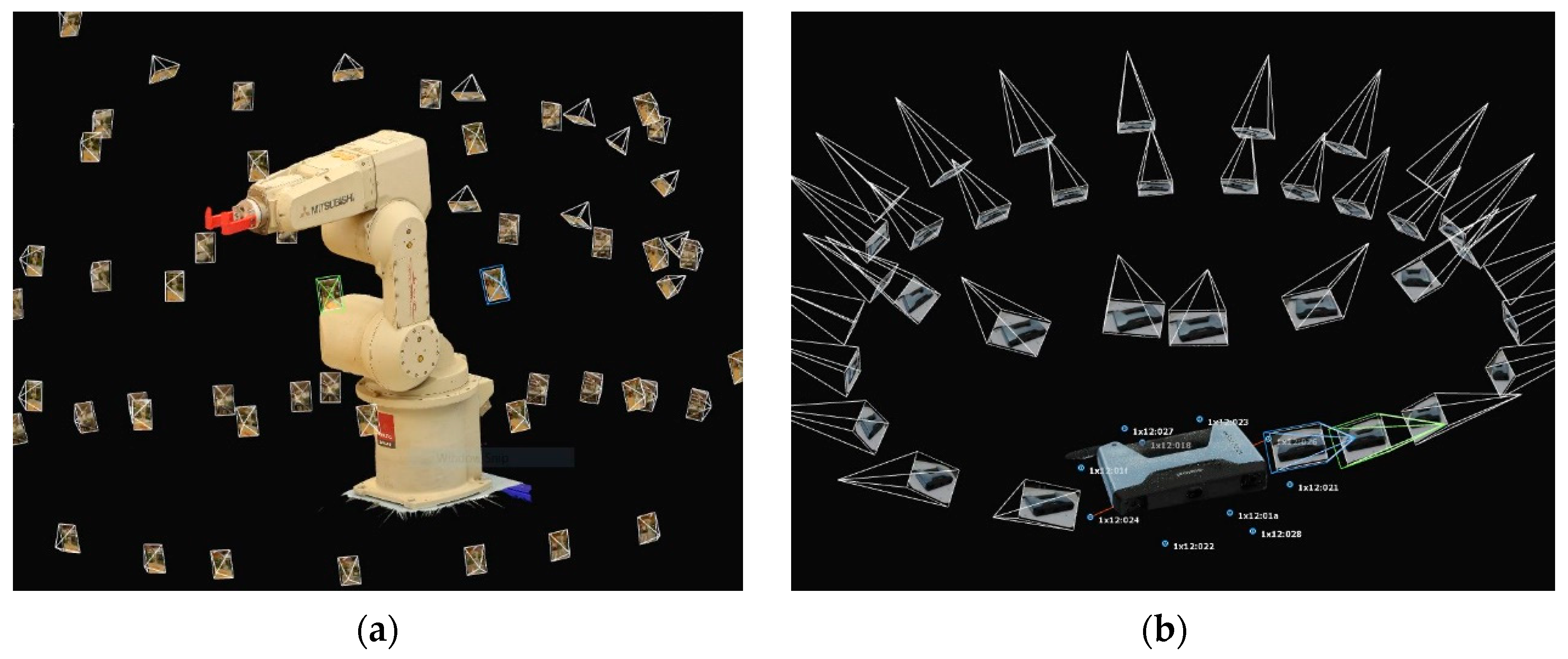
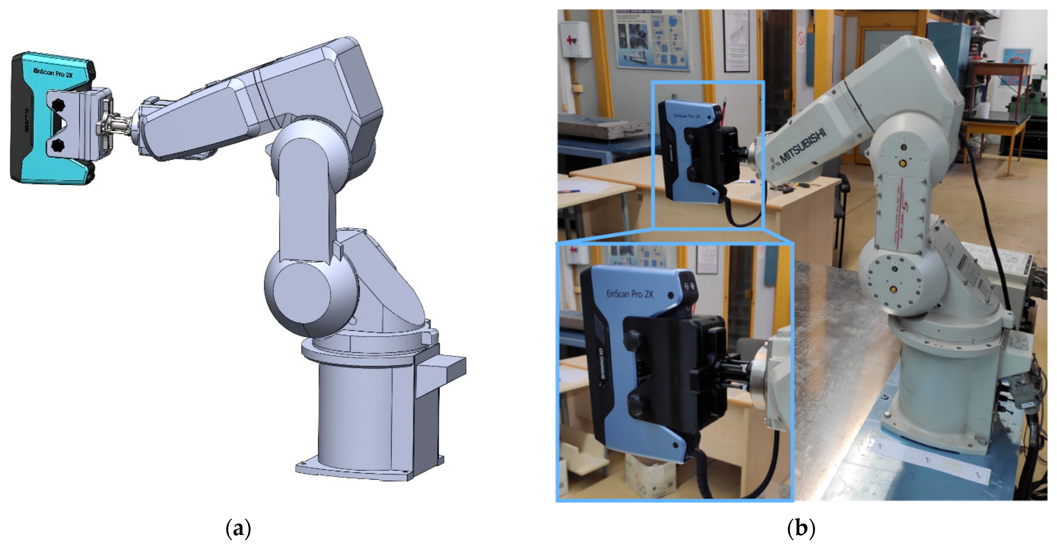
3.1. Photogrammetric 3D Digitization

The 3D digitization process begins with setting up the photo capture equipment and the scene environment. The physical objects used in this process, the Mitsubishi robotic arm, model RV-3SDB-S15 (Mitsubishi Electric, Tokyo, Japan) [47], and the EinScan Pro 2X (Shining 3D, Hangzhou, China) [48] optical 3D scanner, are shown in Figure 3a and Figure 3b, respectively. For photo capturing, a Canon EOS 1200D camera with an APS-C 18-megapixel CMOS sensor and EF-S 18–55 mm f/3.5–5.6 IS II lens was used. There are no limitations in using this camera and the specified lens. The main influence on the photogrammetric accuracy is the image quality, which depends mostly on lighting conditions, image resolution (sensor size), and lens type (fisheye, normal, wide, etc.). The camera was mounted on a tripod and moved around the robotic arm in five concentric rings, moving from bottom to top, and around the 3D scanner in two rings. The increment angle from shot to shot was approximately 10 to 15 degrees. A total of 169 high-resolution photographs (5184 × 3456 px) were captured. The 3D scanner was photographed on a rotary table, where 37 photos were captured, but only one half of the 3D scanner was sufficient for the reconstruction. By using the tripod, potential shake and blur effects were eliminated. The scale of the objects was determined by placing coded markers around the object and placing them on a turntable, with a known and defined distance between them. The coded markers were generated by photogrammetric software and printed on standard A4 white paper. These markers can be automatically detected by photogrammetric software in the image processing stage. Scale validation was conducted by measuring easily accessible features using a caliper with an accuracy of 0.05 mm and comparing with measurements on 3D models.
The lighting conditions were carefully optimized for the photographic camera settings, such as aperture (f11), shutter speed (3/5 s), and ISO (200), which provide the appropriate depth of field, ensuring high-quality images for 3D digitization.
After the photos were successfully acquired, they were processed using Reality Capture v1.5 (Epic Games, Cary, NC, USA) photogrammetric software, and a mesh 3D model was generated. With Reality Capture, it is possible to obtain accurate 3D models, even those with sub-millimeter resolution [49]. The resolution of the 3D model depends on the quality and resolution of the images and the distance of the capturing camera from the object. The basic workflow for photogrammetry reconstruction was used, and it included importing images into software, aligning images, creating a sparse point cloud, mesh reconstruction, and texture application. Figure 4a,b show the 3D models with the texture and camera locations obtained by photogrammetric reconstruction.
An automated marker detection option for marker detection was used, which was based on the markers with which the scale was defined. Photogrammetric 3D models usually require additional post-processing because of the presence of noise and extra geometry generated from the environment. Post-processing involves several key steps, including noise removal, polygon reduction, hole filling, and geometry repair. For noise removal, a smoothing method was used, and the threshold value was set to 0.1 mm, which eliminated most of the noise. The purpose of polygon reduction is to reduce the number of sufficient polygons to maintain accuracy. The smaller holes were filled with an automated tool, while the larger holes were filled manually. This post-processing has a negligible impact on the accuracy but improves the quality of the polygonal model itself and facilitates the next phase.
Figure 5a,b illustrate the post-processed and scaled polygonal mesh models of a robotic arm and 3D scanner, respectively.

3.2. Reverse Engineering

The process of RE is conducted by applying a combination of different CAD modeling techniques. Thus, 3D mesh models of the robotic arm and 3D scanner represent starting references for CAD modeling. For 3D modeling, SolidWorks v2022 (Dassault Systèmes SE, Vélizy-Villacoublay, France) software was used. The sketch geometry was defined by measuring distances and angles from referenced meshes, utilizing basic and advanced CAD features. The resulting CAD models of the robotic arm and 3D scanner are shown in Figure 6a and Figure 6b, respectively. The end of the robotic arm demands accuracy and precision for proper assembly (Figure 6a).
Special attention is given to computer-aided inspection (CAI), which includes a comparison of the 3D polygonal mesh model and reconstructed CAD model of the 3D scanner (Figure 7). Figure 7 shows that the clamping areas are reconstructed with high accuracy.

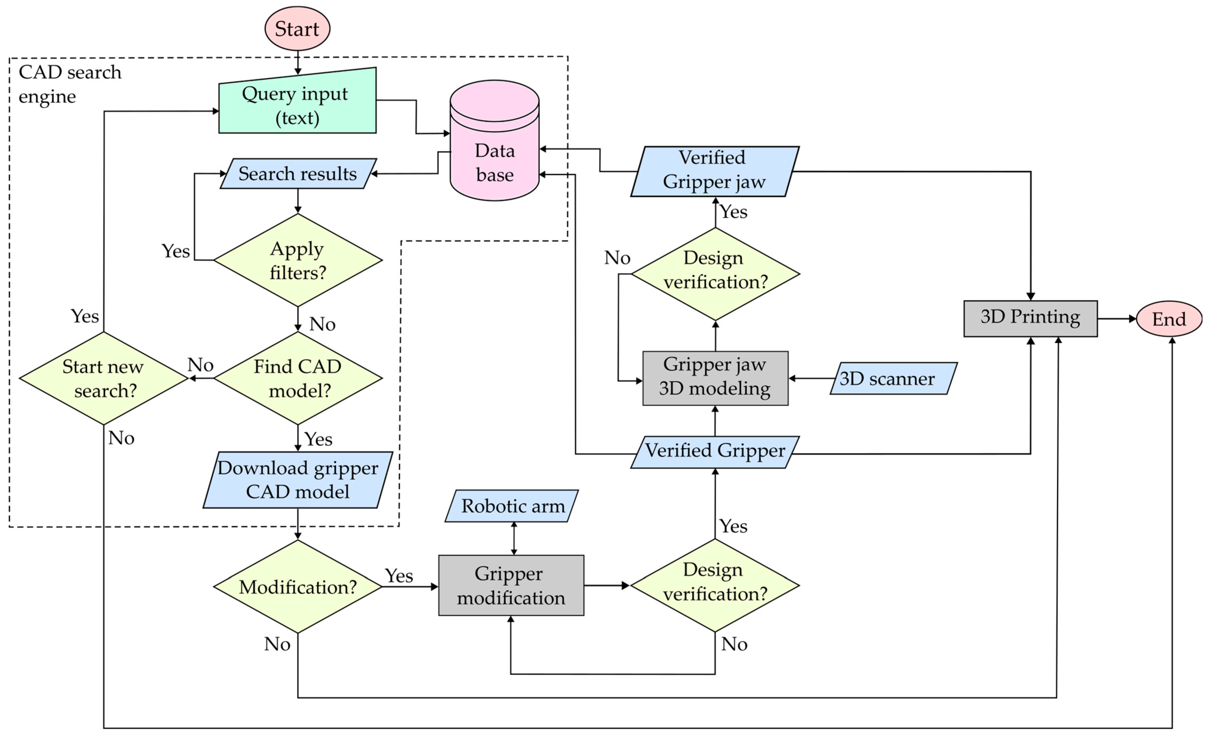
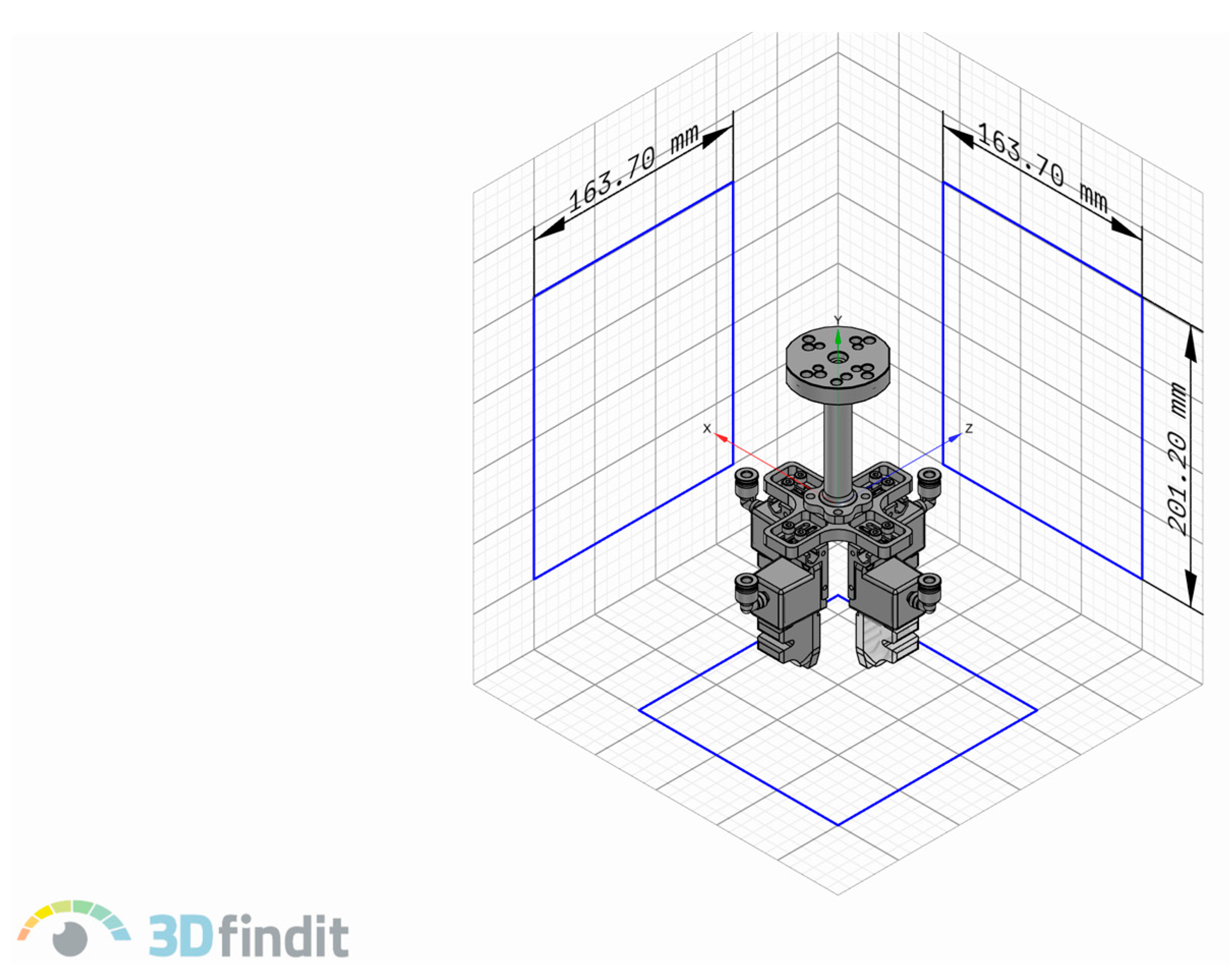
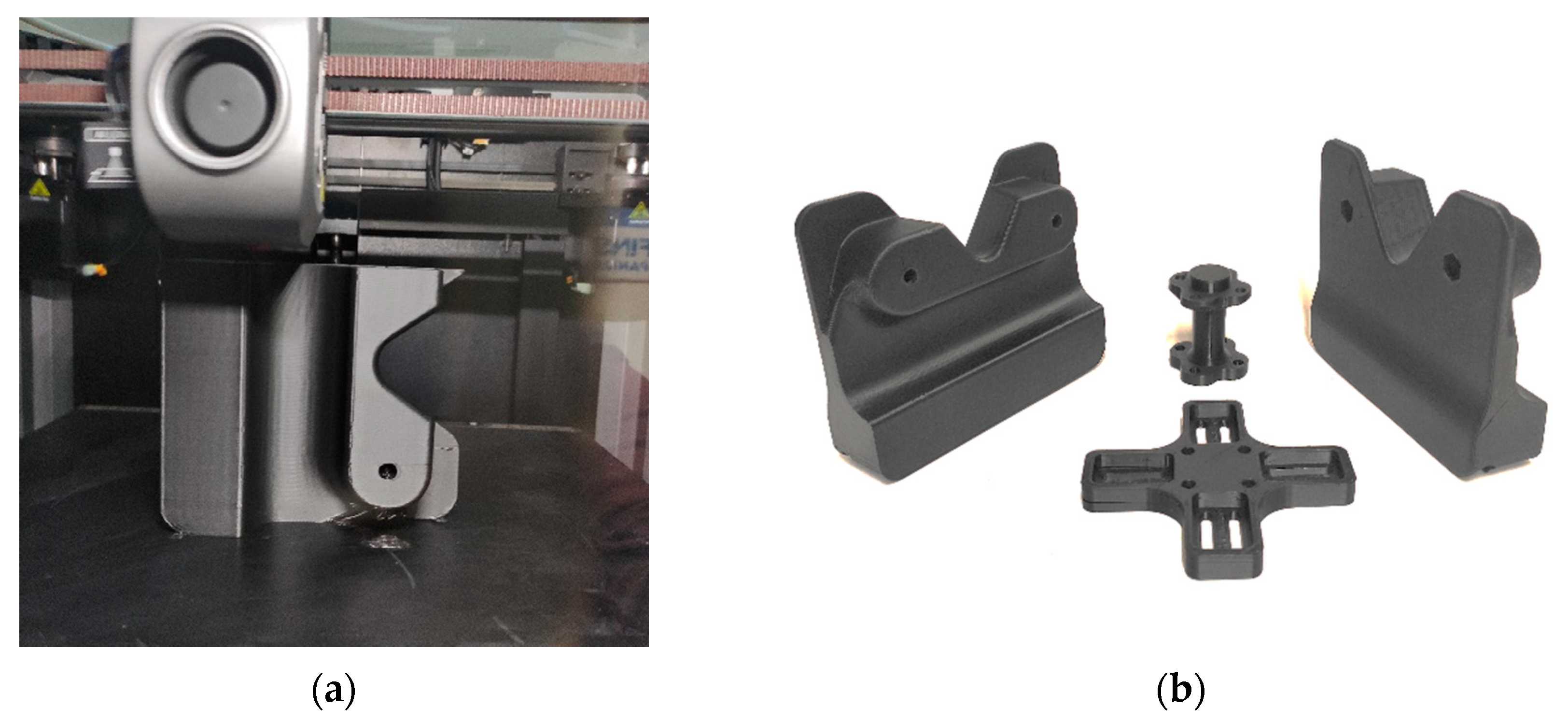
3.3. Gripper Search, 3D Modeling, and 3D Printing

The prerequisites for users to use the 3Dfindit platform are that they must be registered and logged in. Figure 8 shows the interface of the 3Dfindit platform with the final search results. The procedure for the search was as follows: First, in the search query (red frame no. 1), the word “gripper” was typed, after which the platform offered results of around 25,000 matches. To reduce the number of matches, filtering over keywords was applied. In the Keywords field, the words “flexible” and “robot” were entered, and the “and” operators were selected (red frame no. 2). This resulted in three matching hits. The first hit in the list was then chosen for further examination (red frame no. 3).
The selected 3D model of the potential gripper model was opened and examined. Its dimensions were checked and approved, the cross-sections analyzed, and the available 3D documentation evaluated (Figure 9). Based on those data, the examined gripper was then selected and downloaded in CAD file format for further processing. Gripper modification was necessary because the length of the main body had adjusted to the length of the fixing screws. Also, the included flexible jaws were removed.
Figure 10a shows the positioning of the initial jaw block according to the 3D scanner. The block dimensions were adjusted to the handle of the 3D scanner to ensure full utilization of the available surface. Figure 10b presents the result of the applied Boolean intersection function. The final jaw model is shown in Figure 10c, featuring added elements such as fillets, holes, and a cut-extruded groove for mounting to the gripper body. In Figure 10d, the final gripper assembly is presented.
Figure 11 shows the geometry validation of the gripper jaws in comparison to the 3D scanner. The interference detection method in SolidWorks was used for the geometry validation of the gripper jaws. This tool enables the detection of interference regions on parts in the assembly (red regions in Figure 11).
The parts were 3D-printed using an FDM Creality K1 MAX (Shenzhen Creality 3D Technology Co., Ltd., Shenzhen, China) 3D printer (Figure 12a). The printing material was black polylactic acid (PLA) plastic. Table 1 shows the 3D-printed part names and 3D printing parameters, and Table 2 presents the other standard parts used for assembly.
The final stage was the assembly of the 3D scanner and gripper on the robotic arm. Figure 13a shows the assembled CAD model that represents a digital twin, and Figure 13b represents the real condition.

4. Discussion

Based on the presented results, the physical adaptation of an articulated robotic arm and the integration of a handheld optical 3D scanner can be successfully realized with low-cost investments. First of all, the choice of the photogrammetric method for 3D digitization is based on its minimal equipment requirements, free software for image processing, the speed of 3D digitization, and the resulting quality of the 3D model. It is also used to demonstrate the strength, flexibility, and simplicity of the 3D digitization method. Additionally, the potential issues with camera stability and image quality, as mentioned, are reduced by using a turntable and tripod. Establishing the scale and overcoming the inherent dimensionless nature of photogrammetric 3D digitization ensure that the resulting models are dimensionally accurate [50].
The choice of Reality Capture v1.5 software for processing the images into a 3D mesh was based on a lack of literature sources and free access [51]. A small amount of scanning spray was applied to decrease the influence of surface reflection and the lack of texture of the objects before image acquisition. The software obtained dense point clouds and, after that, the 3D polygonal mesh models. Then, textures were applied to improve the realism of the models. In some fields, such as computer graphics, this is considered an advantage, but from a geometric point of view, texture does not influence the accuracy of the models. Post-processing to address the presence of noise and undesired geometry from the environment, with the goal of their elimination, was conducted.
The design intent approach was used for RE to transform a 3D mesh model into a fully detailed and functional CAD model. This step is critical because the size and orientation of geometric elements based on the reference mesh must be assumed. Validation of geometric accuracy was conducted through CAI, which is one of the state-of-the-art methods for validation and comparative analysis. Special attention was given to ensuring accuracy in the design of the robotic arm’s end, which required precision for functional compatibility. Also, the arrangement of the M4 threaded holes as per the Standard Specifications Manual was created [41].
3Dfindit has proven to be a very useful engineering tool for reducing the search time for existing products, but also for the modification and rapid adaptation of existing ones. The types of searches it offers are very diverse, as are the different formats in which models can be downloaded for free. Another great advantage of the 3Dfindit platform is that the user can store the created modified 3D model in the database so that other users can also benefit from it.
The detected interference regions (Figure 11) ensure a satisfactory contact area between the jaws and the 3D scanner, when the jaws are fully closed. The maximal overlap thickness of 0.15 mm in interference regions guarantees acceptable clamping force.
The jaw 3D modeling approach can be easily applied to other types of mobile handheld 3D scanners without changes in the workflow steps. Finally, by applying additive manufacturing technologies, a fully functional product can be produced in a very short time. The FDM 3D printing technique is ideal for the rapid and cost-effective prototyping of medium-complexity components, such as gripper jaws. The most common FDM 3D printing materials are ABS (acrylonitrile butadiene styrene) and PLA (polylactic acid). FDM printers are widely available and easy to use. By varying the 3D printing parameters from Table 1, the mechanical properties of the jaw can be significantly influenced. The selected parameters used for 3D printing the jaw were satisfactory, considering the weight of the 3D scanner of 1.3 kg. This enables quick and easy adaptation of the robotic arm for new tasks such as 3D scanning and quality control.

5. Conclusions

This paper presents a detailed description of a methodology for the physical adaptation of a robotic arm into a 3D scanning system. The methodology consists of two methods. The first method focuses on converting existing physical components into digital ones through 3D digitization and reverse engineering, while the second method aims to find a suitable gripper using available CAD model search platforms. With the necessary jaw modifications, the gripper is adapted to a specific 3D scanner, and all customized elements are obtained using a 3D printer. It can be concluded that such modifications, with very little investment in obsolete robotic arms that can no longer meet production needs, have a chance of being used for other purposes.
Further research will focus on advanced materials investigations of the gripper (different composite and 3D printing materials), which could improve its strength, flexibility, and ability to handle different handheld 3D scanners. Therefore, further work could be conducted to optimize the robotic arm motion control algorithms for precise and faster scanning operation based on scanned part geometry and feature complexity, as well as robot configurations.

Author Contributions

Conceptualization, D.L. and M.M.; methodology, D.B., D.L., M.M. and Z.S.; validation, M.S. (Mirko Sokovic) and D.L.; investigation, D.B. and Z.S.; resources, D.B. and D.L.; data curation, Z.S.; writing—original draft preparation, D.B., M.S. (Mario Sokac) and Z.S.; writing—review and editing, M.S. (Mario Sokac); visualization, M.S. (Mario Sokac); supervision, M.S. (Mirko Sokovic); project administration, M.M.; funding acquisition, M.S. (Mirko Sokovic). All authors have read and agreed to the published version of the manuscript.

Funding

This research received no external funding.

Institutional Review Board Statement

Not applicable.

Informed Consent Statement

Not applicable.

Data Availability Statement

The original contributions presented in this study are included in the article. Further inquiries can be directed to the corresponding author.

Conflicts of Interest

The authors declare no conflict of interest.

References

  1. Yin, X.; He, W.; Wang, J.; Peng, S.; Cao, Y.; Zhang, B. Health State Assessment Based on the Parallel–Serial Belief Rule Base for Industrial Robot Systems. Eng. Appl. Artif. Intell. 2025, 142, 109856. [Google Scholar] [CrossRef]
  2. Milošević, M.; Lukić, D.; Borojević, S.; Antić, A.; Đurđev, M. A Cloud-Based Process Planning System in Industry 4.0 Framework. In Proceedings of the 4th International Conference on the Industry 4.0 Model for Advanced Manufacturing; Lecture Notes in Mechanical Engineering; Springer: Cham, Switzerland, 2019; pp. 202–211. [Google Scholar] [CrossRef]
  3. Xu, Y.; Lv, M.; Xu, Q.; Xu, R. Design and Analysis of a Robotic Gripper Mechanism for Fruit Picking. Actuators 2024, 13, 338. [Google Scholar] [CrossRef]
  4. Oks, S.J.; Jalowski, M.; Lechner, M.; Mirschberger, S.; Merklein, M.; Vogel-Heuser, B.; Möslein, K.M. Cyber-Physical Systems in the Context of Industry 4.0: A Review, Categorization and Outlook. Inf. Syst. Front. 2024, 26, 1731–1772. [Google Scholar] [CrossRef]
  5. Stepanić, P.; Dučić, N.; Stanković, N. Development of Artificial Neural Network Models for Vibration Classification in Machining Process on Brownfield CNC Machining Center. J. Prod. Eng. 2024, 27, 16–20. [Google Scholar] [CrossRef]
  6. Hozdić, E.; Makovec, I. Evolution of the Human Role in Manufacturing Systems: On the Route from Digitalization and Cybernation to Cognitization. Appl. Syst. Innov. 2023, 6, 49. [Google Scholar] [CrossRef]
  7. Kamali, M.; Atazadeh, B.; Rajabifard, A.; Chen, Y. Advancements in 3D Digital Model Generation for Digital Twins in Industrial Environments: Knowledge Gaps and Future Directions. Adv. Eng. Inform. 2024, 62, 102929. [Google Scholar] [CrossRef]
  8. Chen, K.; Zhao, B.; Zhang, Y.; Zhou, L.; Niu, K.; Jin, X.; Xu, B.; Yuan, Y.; Zheng, Y. Digital Twin-Based Vibration Monitoring of Plant Factory Transplanting Machine. Appl. Sci. 2023, 13, 12162. [Google Scholar] [CrossRef]
  9. Wang, Z.; Wang, L.; Martínez-Arellano, G.; Griffin, J.; Sanderson, D.; Ratchev, S. Digital Twin Based Photogrammetry Field-of-View Evaluation and 3D Layout Optimisation for Reconfigurable Manufacturing Systems. J. Manuf. Syst. 2024, 77, 1045–1061. [Google Scholar] [CrossRef]
  10. ISO 8373:2021; Robotics—Vocabulary. International Organization for Standardization: Geneva, Switzerland, 2021.
  11. Singh, G.; Banga, V.K. Robots and Its Types for Industrial Applications. Mater. Today Proc. 2022, 60, 1779–1786. [Google Scholar] [CrossRef]
  12. The Basics of Industrial Robots|Industrial Robots by Kawasaki Robotics. Available online: https://kawasakirobotics.com/asia-oceania/industrial-robots/ (accessed on 4 January 2025).
  13. Onstein, I.F.; Bjerkeng, M.; Martinsen, K. Automated Tool Trajectory Generation for Robotized Deburring of Cast Parts Based on 3D Scans. Procedia CIRP 2023, 118, 507–512. [Google Scholar] [CrossRef]
  14. Khoat, N.X.; Hoa, C.T.V.; Khoa, N.B.N.; Dung, N.M. Trajectory Planning and Tracking Control for 6-DOF Yaskawa Manipulator Based on Differential Inverse Kinematics. J. Robot. Control (JRC) 2024, 5, 2035–2047. [Google Scholar] [CrossRef]
  15. Ulrich, M.; Steger, C.; Butsch, F.; Liebe, M. Vision-Guided Robot Calibration Using Photogrammetric Methods. ISPRS J. Photogramm. Remote Sens. 2024, 218, 645–662. [Google Scholar] [CrossRef]
  16. Vasiljević, S.; Rajković, D.; Đorđević, M.; Kostić, S.; Stanojević, M. Application of Innovative Mechatronic Systems in Product Design, Development and Production. J. Prod. Eng. 2024, 27, 13–21. [Google Scholar] [CrossRef]
  17. Zong, Y.; Liang, J.; Pai, W.; Ye, M.; Ren, M.; Zhao, J.; Tang, Z.; Zhang, J. A High-Efficiency and High-Precision Automatic 3D Scanning System for Industrial Parts Based on a Scanning Path Planning Algorithm. Opt. Lasers Eng. 2022, 158, 107176. [Google Scholar] [CrossRef]
  18. Zheng, Y.; Liu, W.; Zhang, Y.; Ding, H.; Li, J.; Lu, Y. Laser In-Situ Measurement in Robotic Machining of Large-Area Complex Parts. Measurement 2025, 241, 115718. [Google Scholar] [CrossRef]
  19. Itadera, S.; Domae, Y. Motion Priority Optimization Framework towards Automated and Teleoperated Robot Cooperation in Industrial Recovery Scenarios. Robot. Auton. Syst. 2025, 184, 104833. [Google Scholar] [CrossRef]
  20. Laman, E.; Maslan, M.N.; Ali, M.M.; Abdullah, L.; Zamri, R.; Syafiq, M.; Mohamed, S.; Zainon, M.; Noorazizi, M.S.; Sudianto, A. Design of an Internet of Things Based Electromagnetic Robotic Arm for Pick and Place Applications. Malays. J. Compos. Sci. Manuf. 2020, 2, 12–20. [Google Scholar] [CrossRef]
  21. Yusoff, Z.M.; Nordin, S.A.; Markom, A.M.; Mohammad, N.N. Wireless Hand Motion Controlled Robotic Arm Using Flex Sensors. Indones. J. Electr. Eng. Comput. Sci. 2023, 29, 133–140. [Google Scholar] [CrossRef]
  22. Fitria, S.; Nawawi, Z.; Kurnia, R.F.; Yuniarti, D.; Dewi, T. Simulation of Robot Arm System Control Using Fuzzy Logic. Sriwij. Electr. Comput. Eng. J. 2024, 1, 20–29. [Google Scholar] [CrossRef]
  23. Elfasakhany, A.; Yanez, E.; Baylon, K.; Salgado, R. Design and Development of a Competitive Low-Cost Robot Arm with Four Degrees of Freedom. Mod. Mech. Eng. 2011, 1, 47–55. [Google Scholar] [CrossRef]
  24. Arnarson, H. Intelligent Self- and Reconfigurable Manufacturing System. Ph.D. Thesis, UiT The Arctic University of Norway, Tromsø, Norway, 2023. [Google Scholar]
  25. Dzedzickis, A.; Subačiūtė-Žemaitienė, J.; Šutinys, E.; Samukaitė-Bubnienė, U.; Bučinskas, V. Advanced Applications of Industrial Robotics: New Trends and Possibilities. Appl. Sci. 2021, 12, 135. [Google Scholar] [CrossRef]
  26. Ma, W.; Hu, T.; Zhang, C.; Chen, Q. Adaptive Remanufacturing for Freeform Surface Parts Based on Linear Laser Scanner and Robotic Laser Cladding. Robot. Comput.-Integr. Manuf. 2025, 91, 102855. [Google Scholar] [CrossRef]
  27. Wu, J.; Jiang, H.; Wang, H.; Wu, Q.; Qin, X.; Dong, K. Vision-Based Multi-View Reconstruction for High-Precision Part Positioning in Industrial Robot Machining. Measurement 2025, 242, 116042. [Google Scholar] [CrossRef]
  28. Gu Kim, H.; Hwa Hong, T.; Kim, D.; Hyeon Kim, S. An Experimental Study of Ultrasonic-Knife Cutting for a Woven Carbon Fiber Preform by an Industrial Robot. Manuf. Lett. 2024, 41, 581–587. [Google Scholar] [CrossRef]
  29. Toshev, R.; Bengs, D.; Helo, P.; Zamora, M. Advancing Free-Form Fabrication: Industrial Robots’ Role in Additive Manufacturing of Thermoplastics. Procedia Comput. Sci. 2024, 232, 3131–3140. [Google Scholar] [CrossRef]
  30. Diller, E.; Sitti, M. Three-Dimensional Programmable Assembly by Untethered Magnetic Robotic Micro-Grippers. Adv. Funct. Mater. 2014, 24, 4397–4404. [Google Scholar] [CrossRef]
  31. Milojević, A.; Linß, S.; Ćojbašić, Ž.; Handroos, H. A Novel Simple, Adaptive, and Versatile Soft-Robotic Compliant Two-Finger Gripper With an Inherently Gentle Touch. J. Mech. Robot. 2021, 13, 011015. [Google Scholar] [CrossRef]
  32. Automated 3D Scanning and Inspection of High-Precision Stands. Available online: https://www.creaform3d.com/en/solutions/automated-3d-scanning-and-inspection-high-precision-stands (accessed on 13 March 2025).
  33. RoboticScan|Professional 3D Scanning Solutions|Artec 3D. Available online: https://www.artec3d.com/portable-3d-scanners/robotic-scan (accessed on 13 March 2025).
  34. ZEISS ScanBox: Optical 3D Coordinate Measuring Machine|Automation. Available online: https://www.zeiss.com/metrology/en/systems/optical-3d/automated-solutions/scanbox.html (accessed on 13 March 2025).
  35. Peng, Q.; Sanchez, H. 3D Digitizing Technology in Product Reverse Design. Proc. Can. Eng. Educ. Assoc. (CEEA) 2011, 2, 1–10. [Google Scholar] [CrossRef]
  36. Kumar, A.; Jain, P.K.; Pathak, P.M. Reverse Engineering in Product Manufacturing: An Overview. AAAM Int. Sci. Book 2013, 39, 665–678. [Google Scholar] [CrossRef]
  37. Budak, I.; Santosi, Z.; Stojakovic, V.; Korolija Crkvenjakov, D.; Obradovic, R.; Milosevic, M.; Sokac, M. Development of Expert System for the Selection of 3D Digitization Method in Tangible Cultural Heritage. Teh. Vjesn.—Tech. Gaz. 2019, 26, 837–844. [Google Scholar] [CrossRef]
  38. Buonamici, F.; Carfagni, M.; Furferi, R.; Governi, L.; Lapini, A.; Volpe, Y.; Gopinath, G.; Vamsi, B.C.; Vinay, N.; Buonamici, F.; et al. Reverse Engineering of Mechanical Parts: A Template-Based Approach. J. Comput. Des. Eng. 2018, 5, 145–159. [Google Scholar] [CrossRef]
  39. Raja, V.; Fernandes, K.J. Reverse Engineering; Raja, V., Fernandes, K.J., Eds.; Springer Series in Advanced Manufacturing; Springer: London, UK, 2008; Volume 101, ISBN 978-1-84628-855-5. [Google Scholar]
  40. CAD Content Platform for Engineers, Architects, Purchasers. Available online: https://www.3dfindit.com/en/ (accessed on 15 December 2024).
  41. 3D Models and Modelling Software|MacOdrum Library. Available online: https://library.carleton.ca/services/3d-printing/3d-models-and-modelling-software (accessed on 10 January 2025).
  42. 3D Models Search Engines in 2024—Asseter. Available online: https://asseter.ai/3d-models-search-engines-in-2024/ (accessed on 10 January 2025).
  43. 7 Best Search Engines for 3d Printing Models. Available online: https://www.3ddrucklife.de/post/7-best-search-engines-for-3d-printing-models-stl-finder?srsltid=AfmBOoqasBLO9oMsiNokwx2T_uvyL1f2gU2rQsSOU6rttVIAZus7Z2hw (accessed on 10 January 2025).
  44. Get Started with 3Dfindit. Available online: https://www.3dfindit.com/en/engiclopedia/get-started-with-3-dfindit (accessed on 10 January 2025).
  45. Perak, V. Influence of infill density and number of layers on mechanical properties of 3D printed pla and abs sandwich. Adv. Eng. Lett. 2024, 3, 154–163. [Google Scholar]
  46. Hozdić, E. Characterization and Comparative Analysis of Mechanical Parameters of FDM- and SLA-Printed ABS Materials. Appl. Sci. 2024, 14, 649. [Google Scholar] [CrossRef]
  47. Mitsubishi Industrial Robot. RV-3SD/3SDJ/3SDB/3SDBJ Series; Standard Specifications Manual; Mitsubishi Industrial Robot: Ratingen, Germany, 2012. [Google Scholar]
  48. Elfasakhany, A.; Yanez, E.; Baylon, K.; Salgado, R. EinScan Pro 2X Plus—Handheld Industrial Scanner|EinScan. Available online: https://www.einscan.com/handheld-3d-scanner/2x-plus/ (accessed on 15 January 2025).
  49. RealityCapture—3D Models from Photos and/or Laser Scans. Available online: https://www.capturingreality.com/ (accessed on 13 January 2025).
  50. El-Din Fawzy, H. Study the Accuracy of Digital Close Range Photogrammetry Technique Software as a Measuring Tool. Alex. Eng. J. 2019, 58, 171–179. [Google Scholar] [CrossRef]
  51. Kingsland, K. Comparative Analysis of Digital Photogrammetry Software for Cultural Heritage. Digit. Appl. Archaeol. Cult. Herit. 2020, 18, e00157. [Google Scholar] [CrossRef]
Figure 1. Workflow diagram of the digital transformation method.
Applsci 15 05377 g001
Figure 2. Workflow diagram of the development of a fully useable 3D-printed connection element.
Applsci 15 05377 g002
Figure 3. Physical components for 3D digitization: (a) Mitsubishi articulated robotic arm, model RV-3SDB-S15; (b) Shining 3D EinScan Pro 2X optical 3D scanner.
Applsci 15 05377 g003
Figure 4. Photogrammetric 3D digitization: (a) Mitsubishi articulated robotic arm; (b) Shining 3D EinScan Pro 2X Optical 3D scanner.
Applsci 15 05377 g004
Figure 5. Polygonal mesh models: (a) Mitsubishi articulated robotic arm; (b) Shining 3D EinScan Pro 2X Optical 3D scanner.
Applsci 15 05377 g005
Figure 6. CAD models: (a) Mitsubishi articulated robotic arm; (b) Shining 3D EinScan Pro 2X Optical 3D scanner.
Applsci 15 05377 g006
Figure 7. Geometry validation of reconstructed CAD model of 3D scanner by CAI.
Applsci 15 05377 g007
Figure 8. 3Dfindit final search results for gripper with included filters.
Applsci 15 05377 g008
Figure 9. Gripper 3D documentation [40].
Applsci 15 05377 g009
Figure 10. The gripper 3D modeling phases: (a) 3D scanner with initial jaw block; (b) intersection result between jaw block and 3D scanner; (c) finished gripper jaw CAD model; (d) gripper assembly.
Applsci 15 05377 g010
Figure 11. Clamping areas and geometry validation of gripper jaws in comparison to 3D scanner.
Applsci 15 05377 g011
Figure 12. The 3D printing results: (a) 3D printing of gripper jaw; (b) 3D-printed gripper parts.
Applsci 15 05377 g012
Figure 13. Adopted Mitsubishi articulated robotic arm: (a) digital twin; (b) real system.
Applsci 15 05377 g013
Table 1. Three-dimensional printed gripper parts.
Part Name3D Printing Parameters
Infill [%]Weight [g]Time [min]
Left jaw4093155
Right jaw4093155
Cross body202232
Pillar body301134
Table 2. Other standard parts used for gripper assembly (3D models, source 3Dfindit [40]).
Part Name Dimensions [mm]Quantity
Star Nut Knob ϕ25 × 16 M62
Cylindrical Head Socket Cap Screw M5 × 604
Cylindrical Head Socket Cap ScrewM4 × 104
Hexagon Head BoltM6 × 602
T Nut M44
Hexagon Nut M54
Plain WasherFor M5 screw4
Disclaimer/Publisher’s Note: The statements, opinions and data contained in all publications are solely those of the individual author(s) and contributor(s) and not of MDPI and/or the editor(s). MDPI and/or the editor(s) disclaim responsibility for any injury to people or property resulting from any ideas, methods, instructions or products referred to in the content.

