Article

Investigating the Machining Behavior of the Additively Manufactured Polymer-Based Composite Using Adaptive Neuro-Fuzzy Learning

by
Anastasios Tzotzis
1,*,
Dumitru Nedelcu
2,
Simona-Nicoleta Mazurchevici
2 and
Panagiotis Kyratsis
1
1
Department of Product and Systems Design Engineering, University of Western Macedonia, 50100 Kila Kozani, Greece
2
Department of Manufacturing Engineering, “Gheorghe Asachi” Technical University, 700050 Iasi, Romania
*
Author to whom correspondence should be addressed.
Appl. Sci. 2025, 15(10), 5373; https://doi.org/10.3390/app15105373
Submission received: 27 April 2025 / Revised: 8 May 2025 / Accepted: 9 May 2025 / Published: 12 May 2025
(This article belongs to the Special Issue Innovations in Artificial Neural Network Applications)

Abstract

:
This study presents an experimental and computational investigation into the machinability of additively manufactured (AM) fiber-reinforced PETG during external CNC turning. A series of machining trials were conducted under dry conditions, with cutting speed (Vc), feed (f), and depth-of-cut (ap) as the primary input parameters. The corresponding surface roughness (Ra) and tool-tip temperature (T) were recorded as key output responses. An Adaptive Neuro-Fuzzy Inference System (ANFIS) was developed to model the process behavior, utilizing a 3–3–3 architecture with triangular membership functions. The resulting models demonstrated high predictive accuracy across training, testing, and validation datasets. Experimental results revealed that elevated feed rates and depth-of-cut significantly increase surface roughness, while combinations of high cutting speed and feed contribute to elevated tool temperatures. Multi-objective optimization using the Non-Dominated Sorting Genetic Algorithm 2 (NSGA-II) algorithm was employed to minimize both Ra and T simultaneously. The Pareto-optimal front indicated that optimal performance could be achieved within the range of 100–200 m/min for Vc, 0.054–0.059 mm/rev for f, and 0.512–0.516 mm for ap. The outcomes of this research provide valuable insights into the machinability of reinforced polymer-based AM components and establish a robust framework for predictive modeling and process optimization.

1. Introduction

Surface quality is of utmost interest in machining processes, directly influencing the functional performance, fatigue life, and aesthetic quality of manufactured components. Achieving optimal surface finish is essential across various industries, as it affects properties such as friction, wear resistance, and the ability to form reliable joints. Recent studies have emphasized the importance of controlling surface roughness to ensure the structural integrity and performance of machined parts from various materials, such as aluminum alloys [1,2], steels [3,4], and superalloys [5,6]. Specifically, in aerospace applications, precision machining of Ti-6Al-4V titanium alloy is critical due to its poor machinability and tendency to cause rapid tool wear. Optimized tool paths and cooling strategies have been shown to significantly improve surface quality and component life [7]. In the automotive industry, high-speed end milling of AISI 1045 steel has been investigated to meet the requirements for durability and fatigue resistance in engine components [8]. Moreover, in the energy sector, the micro-milling of Inconel 718, a widely used superalloy in turbine components, has demonstrated the effectiveness of tool coatings and feed rate control in minimizing surface defects and enhancing performance under thermal loads [9]. In parallel, the temperature generated during machining plays a pivotal role in determining both the quality of the machined surface and the longevity of the cutting tool. Elevated temperatures can lead to thermal damage, affecting the microstructure [10,11] of the workpiece material and causing issues such as dimensional inaccuracies and surface defects [12,13]. Moreover, excessive heat can accelerate tool wear, leading to increased production costs and downtime. Understanding the thermal aspects of machining is, therefore, crucial for optimizing process parameters and ensuring the quality and efficiency of manufacturing operations.
Carbon-fiber-reinforced polymers (CFRPs) have gained prominence in various sectors, including aerospace, automotive, and sports equipment, due to their exceptional properties. However, machining CFRPs presents unique challenges owing to their anisotropic and heterogeneous nature. Issues such as delamination, fiber pull-out, and matrix cracking are common, adversely affecting the surface integrity of machined components. Recent research has focused on understanding how machining conditions affect the surface quality of CFRP components, aiming to mitigate these defects and enhance the machinability of these advanced materials. Molina-Moya et al. [14] investigated the drilling of CFRP materials with the aim of identifying the optimal conditions by utilizing experimental methodologies and mathematical procedures. Song et al. [15] worked on the CFRP dry drilling by considering the carbon fiber distribution. Doluk et al. [16] dealt with the Al/CFRP stacks milling using diamond tools. Similarly, in the work of Arhamnamazi et al. [17], the drilling of CFRP was investigated with the employment of the central composite design. It is evident that in most studies related to CFRP processing with conventional and non-conventional techniques [18], surface roughness is the primary output parameter investigated, with the researchers trying to deal with the special characteristics and properties of these composites that render them difficult to process.
The advent of additive manufacturing has introduced new complexities in machining, particularly concerning 3D-printed composite parts. The layer-by-layer fabrication process inherent in 3D printing results in unique microstructural characteristics, which can influence the material’s response to machining. Specifically, Fused Filament Fabrication (FFF), a widely used additive manufacturing technique, enables the rapid and cost-effective production of complex geometries. However, the printed components often exhibit poor surface finish, dimensional inaccuracies, and anisotropic mechanical properties due to the layer-by-layer nature of the process. To address these limitations, conventional machining processes such as CNC milling, drilling, or sanding are employed as post-processing steps. These methods improve surface quality, enhance dimensional accuracy, and prepare parts for functional or aesthetic applications. Recent studies emphasize the significance of such hybrid approaches. For example, CNC trimming has been shown to significantly enhance the dimensional precision of FFF-printed PLA parts [19]. Additionally, surface roughness improvements via sanding and other subtractive techniques have been documented [20,21], reinforcing the synergy between FFF and traditional machining in manufacturing workflows.
Recent studies include research in the machinability of 3D-printed composites with an emphasis on CFRP materials. Gómez-Garcíaet al. [22] investigated the machinability of the additively manufactured composite reinforced with short fiber by employing experimental methodologies. El-Mehtedi et al. [23] worked on the face milling of 3D-printed reinforced PETG, focusing on the surface quality. Ma et al. [24] evaluated the behavior of CFRP materials during laser machining by employing experimental work. A work by Cococcetta et al. [25] presents the cryogenic machining of 3D-printed reinforced thermoplastics through experiments. A number of similar studies utilized numerical and computational methods as well, such as the Finite Element Method (FEM) [26] and machine learning [27].
In light of the above, this study aims to contribute to the field of advanced manufacturing by addressing a critical research gap in the CNC turning of 3D-printed CFRP components, particularly during finishing operations. According to Song et al. [28], turning is considered to be one of the most applied processes for CFRP finishing. While CFRP machining has been explored in conventional composites, the unique characteristics of additively manufactured CFRP parts remain largely understudied. The literature review conducted clearly identifies a lack of comprehensive studies on this emerging material class, especially under precise machining conditions. A key novelty of the current work lies in the simultaneous evaluation of surface roughness and cutting tool-tip temperature during the finishing of 3D-printed polymer-based composites, a combination that lacks thorough investigation. This dual-response analysis provides a more holistic understanding of the process-performance relationship, revealing the trade-offs between surface integrity and thermal loads at the tool–workpiece interface.
The choice of ANFIS modeling further enhances the scientific value of the work. Unlike traditional regression or purely data-driven models, ANFIS offers a synergistic integration of fuzzy logic and artificial neural networks, making it particularly well-suited for systems involving nonlinearities, imprecise data, and multi-factor interactions, which are common features in composite machining. According to Ko and Yin [29], ANFIS, ANN, and similar machine learning techniques are ideal for prediction applications regarding surface quality and optimization processes. Especially ANFIS is a methodology that combines the benefits of both ANN and fuzzy logic, making it particularly useful in prediction modeling. In the work by Agu et al. [30], it is shown that ANFIS performed better compared to ANN and outperformed traditional statistical methods such as the Response Surface Methodology (RSM). This hybrid model enables both transparent rule-based inference and adaptive learning capabilities, which are essential for accurately predicting complex machining outcomes with limited experimental data. In summary, this study provides new insights into the finishing of 3D-printed CFRP parts but also introduces a robust modeling and optimization framework that can be extended to similar advanced manufacturing processes involving composite or functionally graded materials.

2. Materials and Methods

Herein, the experimental investigation of the AM, reinforced polymer during CNC turning, is presented. Three standard input parameters were used: cutting speed (Vc), feed (f), and depth-of-cut (ap). Additionally, there were two output responses: surface roughness (Ra) and tool-tip temperature (T). Figure 1 illustrates the basic steps of this study. In the first step, the experimental setup was set, including the BOXFORD 160TCL CNC lathe and the corresponding cutting tool (DCGT090202), the workpieces, as well as the temperature measuring and data acquisition system. In addition, the signal processing regarding the temperature measurements was realized. During step two, the surface roughness and the generated profiles were measured with the mechanical gauge system. Finally, the collected data were used to develop two ANFIS models for the chosen responses, and the optimization process was carried out.

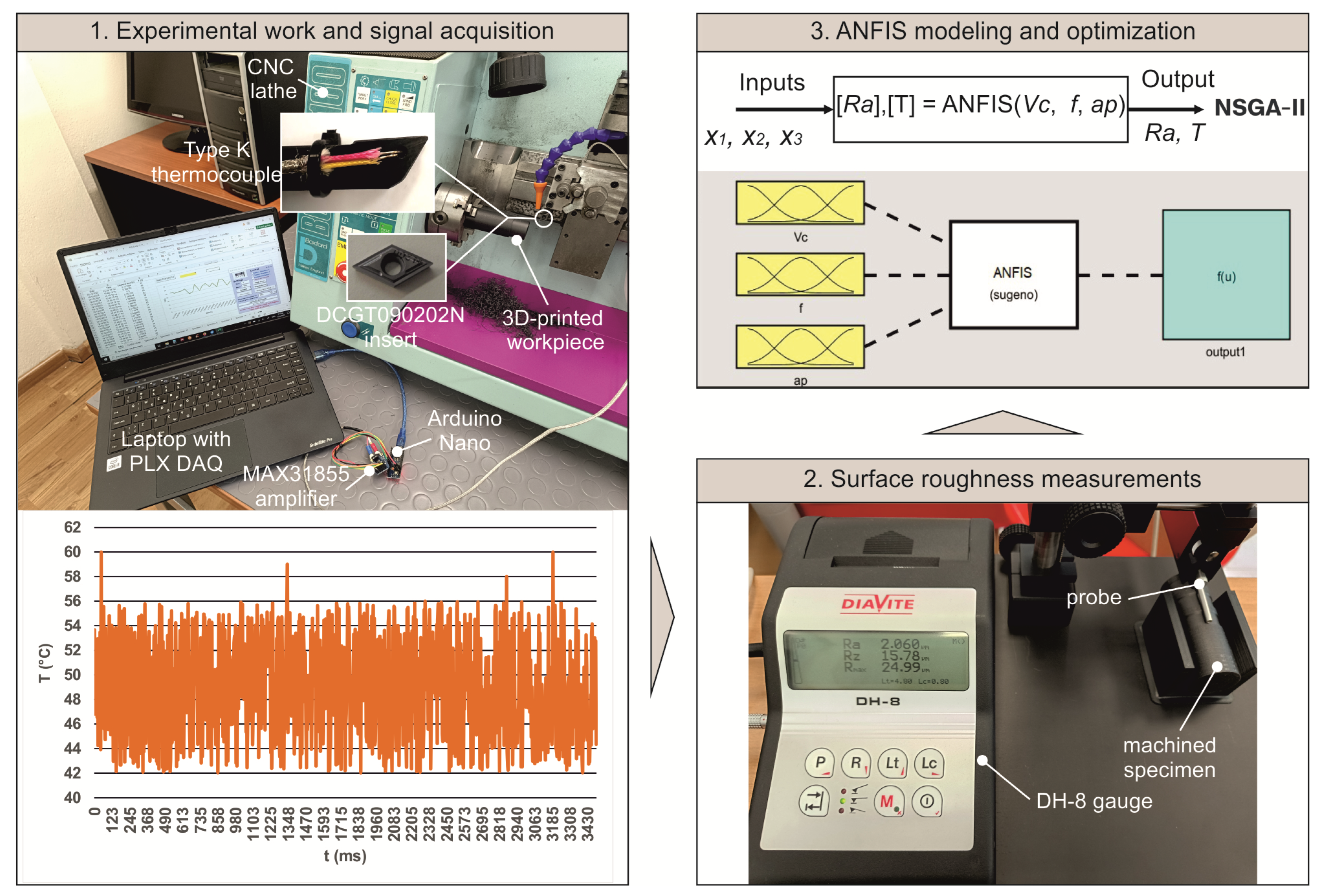
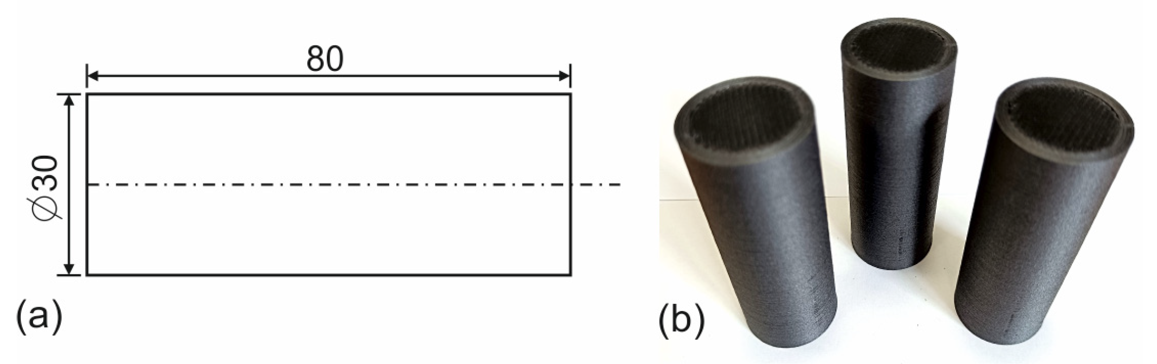
2.1. Experimental Work, Settings, and Workpiece Material

Three levels of each cutting parameter were applied, producing 27 unique combinations with respect to the full factorial design for training the ANFIS model. Another 12 experiments were designed for testing by selecting parameter values from within the range of the study, maintaining a reasonable balance across the input range. To acquire the temperature measurements, a custom sensory system was assembled. A K-type thermocouple coupled with the MAX31855 amplifier was connected to an Arduino Nano. The thermocouple can measure up to 800 °C and has approximately 40 µV/°C sensitivity, ±2 °C repeatability, 0.5 s response time and 1 s time constant. Moreover, it was already precalibrated according to Class 1 accuracy. Additionally, a laptop with the PLX DAQ ver. 2.11 software was used for the data acquisition process. The thermocouple was attached to the back of the tool holder, as shown in Figure 1—step 1, so that its probe comes into contact with the back surface of the tool tip, as described in the work of Akhil et al. [31]. Three cuts were machined on each workpiece, and the surface roughness was measured with the DIAVITE DH-8 in terms of the arithmetic mean Ra by measuring each cut at four anti-diametral points. According to Kohli and Dixit [32], Ra is the most important measurable characteristic of roughness that can describe surface quality adequately. The cutting conditions were selected with respect to previous works of the authors on this material type [13,33].
The 13 workpieces were fabricated with the Fused Filament Fabrication (FFF) method by utilizing the CreatBot D600 Pro 3D printer. Sample fabricated workpieces and their dimensions are shown in Figure 2. The selected material is a polymer-based composite, which belongs to the CFRP material group (80%wt PETG and 20%wt carbon fibers), that is commercially available under the brand name NEEMA3D™ CARBON:PLUS. It utilizes short carbon fibers, as is typical for carbon-fiber-reinforced filaments, which are blended into the thermoplastic matrix. In addition, it presents an elastic modulus equal to 3.8 GPa, a yield strength equal to 52.5 MPa, and a heat deflection temperature of 80 °C. Such materials are preferred in modern manufacturing industries for component fabrication that require a balance between good strength and low weight. According to Vallejo et al. [34], carbon-fiber-reinforced PETG presents relatively good machinability; however, its geometric behavior is worse compared to standard PETG. The printing settings are shown in Table 1.

2.2. Experimental Design and Measurements

The total number of experiments was generated based on the full factorial design of the three parameters and their three levels, in addition to the 12 testing experiments. All 39 experimental results are shown in Table 2, including the surface roughness and the tool-tip temperature.
The normal probability plots were plotted to assess the data point distribution, as shown in Figure 3, by utilizing the Anderson–Darling test [35] and setting the confidence level to 95%. By observing both plots, it is shown that the data points are very close to the line that represents the distribution. It is noted that Figure 3a illustrates the probability plot for Ra and Figure 3b for T. The pattern of the data points across the straight line suggests that they follow the normal distribution. In addition, it is shown that none of the points fall outside the confidence bands, with the exception of one or two points that intersect the bands. Finally, the points of both models are tightly clustered around the distribution line, indicating that both Ra and T measurements have a consistent variance, a fact that supports the normality assumption.
Continuing, Figure 4 illustrates the relation between Ra and T. By observing the trend line, as expected, it is shown that higher tool temperatures are associated with rougher surfaces. Additionally, the data points follow the trend line, a fact that suggests a stronger correlation between tool temperature and surface roughness under dry conditions. This could mean that as temperature increases, the effect on surface roughness is more predictable in dry cutting of the specific material. Finally, a few outliers are evident; however, the general correlation is maintained. This fact is supported by the findings reported in the work by Abhishek et al. [36] for CFRP materials.

3. ANFIS-Based Modeling

The ANFIS is a powerful hybrid modeling approach that combines the learning capabilities of artificial neural networks with the qualitative reasoning of fuzzy logic. It is particularly well-suited for modeling complex, non-linear systems where traditional analytical methods fall short. By integrating fuzzy if–then rules with data-driven training, ANFIS can capture both expert knowledge and experimental trends, offering high interpretability and accuracy. Its layered architecture allows it to adapt membership functions and rule parameters through training, making it an effective tool for prediction, system identification, and optimization tasks in various engineering applications, such as the prediction of surface roughness, cutting forces, and temperatures during machining [37,38,39,40].
The structure of an ANFIS model relies heavily on the definition and configuration of membership functions (MFs), which are fundamental components used to fuzzify the input variables. Each MF represents a linguistic label (e.g., “low”, “medium”, and “high”) and determines how the input values are mapped into fuzzy sets. In this study, a systematic evaluation of ANFIS structures was performed using four commonly used MF types [41]: triangular, trapezoidal, Gaussian, and generalized bell-shaped. These types were chosen for their widespread application, simplicity, and flexibility in representing smooth transitions across input ranges. Twelve combinations were tested for each model, varying the number of MFs per input across 2–2–2, 3–3–3, and 4–4–4 structures. It was found that the triangular MF with a 3–3–3 configuration resulted in the lowest Root Mean Square Error (RMSE) and higher R2, indicating superior predictive performance. RMSE is a metric sensitive to outliers, whereas R2 measures how well predictions explain the variance in the data (closer to 1 is better). Increasing the number of MFs beyond four per input led to model overfitting and higher RMSE, whereas reducing them to two per input (2–2–2) resulted in underfitting and poor accuracy. Therefore, the selected configuration strikes a balance between model complexity and generalization, providing an optimal structure for capturing the underlying patterns in the machining data. The training epochs were set to 30 for all trials since each combination required a different number of epochs for the training RMSE to stabilize. Table 3 presents the findings of the trials for Model I, which relates to Ra, and Model II, which corresponds to temperature.
Figure 5 illustrates the proposed ANFIS structure based on the rules established by Takagi and Sugeno [42]. The training processes and establishment of the models were achieved by utilizing the Fuzzy Logic toolbox of MATLAB R2021a. The first layer is responsible for computing the membership degrees using MFs. The second layer is used to calculate the firing strengths, whereas the third layer normalizes the firing strengths. Inside the fourth layer, the output of rules is calculated using linear functions. Finally, the weighted average of all rule outputs is calculated in the fifth layer.
In the first layer, each node is an adaptive node that computes the membership grade of an input using an MF such as triangular, Gaussian, or bell-shaped. This way, the numerical inputs are converted into fuzzy rules. These outputs can be determined with Equation (1), with Oi being the output for i rules, μ the MF, x, y, and z are the input parameters, and A, B, and C the fuzzy sets.
O i ( 1 ) = μ A i ( x ) , μ B i ( y ) , μ C i ( z )
The second layer can be mathematically described as a set of two fuzzy rules, assuming that x = Vc, y = f, and z = ap, with Equations (2) and (3) [43]. Where fi is the first-order polynomial, and pi, qi, ri, and si are the consequent parameters. In this layer, each node multiplies the incoming signals to represent the firing strength (wi) of a rule, which can be described by Equation (4).
i f x = A 1 a n d y = B 1 a n d z = C 1 t h e n f 1 = p 1 x + q 1 y + r 1 z + s 1
i f x = A 2 a n d y = B 2 a n d z = C 2 t h e n f 2 = p 2 x + q 2 y + r 2 z + s 2
O i ( 2 ) = w i = μ A i ( x ) × μ B i ( y ) × μ C i ( z )
Then, each node calculates the normalized firing strength at the third layer with Equation (5) for j inputs. Consequently, each node computes the output of each rule using the normalized firing strength and a linear output function with Equation (6). Finally, the single node computes the final output by summing all incoming signals with Equation (7).
O i ( 3 ) = w i ¯ = w i j w j
O i ( 4 ) = w i ¯ × f i = w i ¯ × p i x + q i y + r i z + s i
O i ( 5 ) = i w i ¯ f i

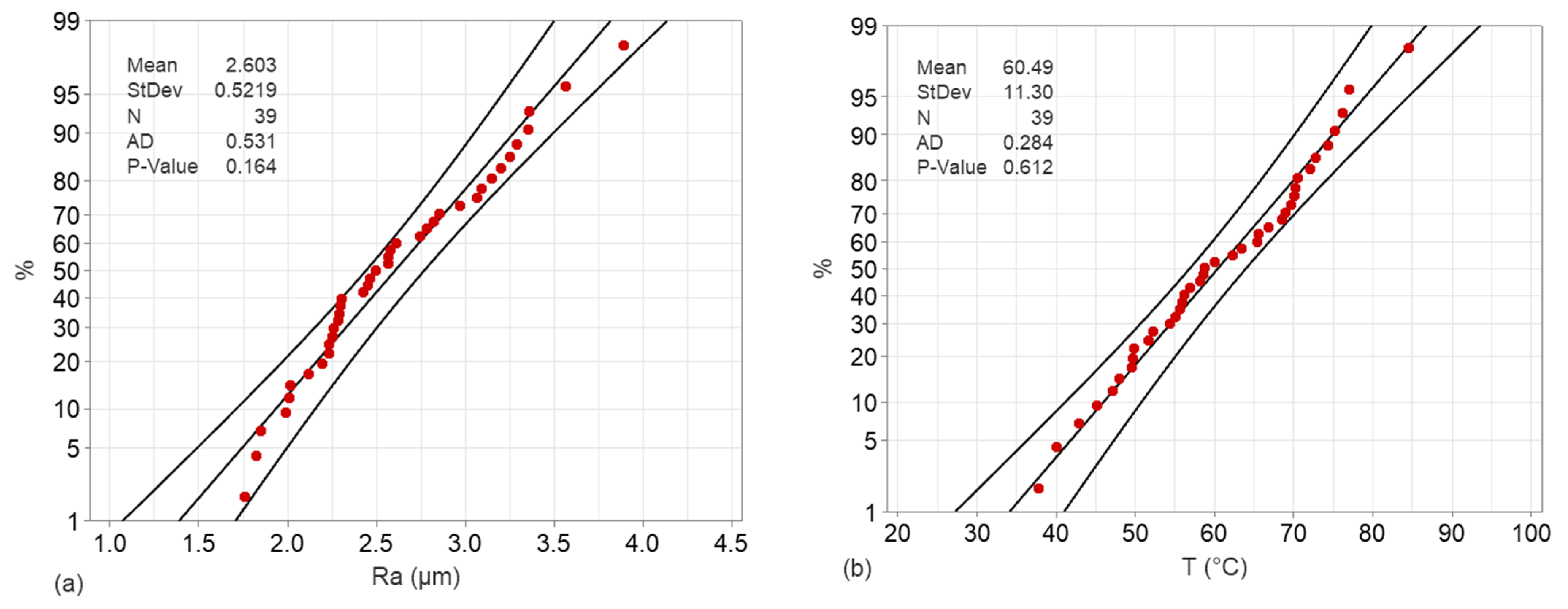
4. Results and Discussion

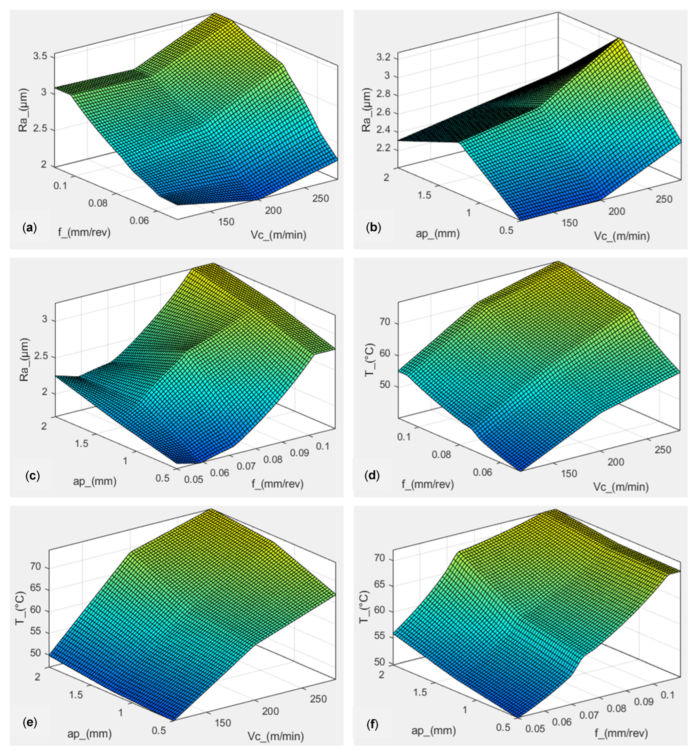
4.1. Investigation of the Inputs’ Influence on the Responses

Figure 6 illustrates the combined influence of the input parameters on the responses. In general, the surface suggests that a strong effect is present for all combinations. Specifically, Figure 6a depicts the combined effect of cutting speed with feed, which is the strongest of all. It is evident that higher feed rates coupled with a cutting speed of over 250 m/min are responsible for increased surface roughness values. This finding is supported by a previous work of the authors for similar conditions [27], where surface roughness was maxed at values beyond 250 m/min. Figure 6b shows how the cutting speed interacts with the depth of cut. It was found that the worst surfaces were generated between 1 mm and 1.5 mm at maxed cutting speed. Contrarily, 0.5 mm depths and low cutting speeds favored quality. Similarly, low feeds close to 0.6 mm/rev and low depths of cut contributed towards better surface quality, as shown in Figure 6c. On the other hand, higher depths always lead to surfaces of low quality. Higher depths of cut were also reported to negatively affect surface roughness when machining pure PETG [44]. In general, a similar magnitude of surface roughness was determined by works on finishing laser machining [45], as well as finishing milling [46] of 3D-printed CFRP components.
Regarding the effects on the generated cutting temperature, Figure 6d indicates that the combination of cutting speed and feed has the most considerable effect, leading to high temperature values when feeds of over 0.1 mm/rev are combined with high levels of cutting speed. The lowest temperature was identified at 0.05 mm/rev feed and 115 m/min cutting speed. As expected, higher speeds and faster tool translations generated more friction and heat, ultimately leading to an increase in temperature. Abhishek et al. [36] reported similar findings regarding the rise in temperature during CFRP composite machining. Continuing, Figure 6e,f confirm that cutting speed is the most influential parameter. In contrast, the depth of cut does not affect the temperature significantly, as opposed to its behavior in terms of the surface roughness. Finally, when combined with feed, it presents a slightly more influential pattern.
In general, the machining of carbon-fiber-reinforced PETG was determined to be more difficult than pure polymer. Ginoux et al. [47] reported constant porosity when PETG testing specimens were machined, irrespective of the printing orientation angle. In contrast, a previous work of the authors [13] identified the 3D-printed CFRP materials as challenging when machined, especially at high feeds and depths, reporting defects at the layer bonding that affect porosity. Despite this issue, the 3D-printed CFRP tends to generate superior surfaces compared to pure polymer when machined at a certain range of conditions. According to El-Mehtedi [48], the carbon fibers, in this case, strengthen material uniformity and structural stability. The results reported in the aforementioned study indicate that milling PETG generates surfaces with roughness values between 5 μm and 8 μm, with feed rate being the dominant parameter. The similarity with this study lies in the feed rate being the most influential factor, whereas the generated surface roughness for CF-PETG is lower, with values below 4 μm. This fact supports the benefits that derive from the addition of carbon fibers in the polymer matrix. Furthermore, another study [49] investigating the dry turning of pure PETG exhibited remarkably higher values of surface roughness, at the range of 30 μm, indicating that 3D-printed carbon-fiber-reinforced polymers produce superior surfaces during machining. Considering the molded counterparts, a study on polyamide milling [50] revealed roughness values as low as approximately 1.2 μm, suggesting that conventionally manufactured polymers tend to produce higher-quality surfaces. Especially during micromachining of conventionally fabricated nanocomposites [51], the produced roughness falls under the range of below 1 μm.
Additionally, machining 3D-printed polymers, particularly those produced via FFF, presents distinct challenges compared to machining conventionally manufactured polymers such as extruded or injection-molded materials. The layer-by-layer construction inherent to FFF introduces anisotropic mechanical properties and surface irregularities, which can lead to increased tool wear and inconsistent surface finishes during machining. For instance, a study comparing the milling of 3D-printed and cast polyamide [50] revealed that FFF parts exhibited lower surface quality and required specific machining parameters to achieve acceptable finishes, whereas cast parts demonstrated more uniform machinability. Similarly, research on 3D printed thermoplastics milling [52] points out the importance of effective heat dissipation through proper chip formation to maintain high surface quality during machining. Furthermore, an analysis of milling parameters on PLA, PETG, and CF-PETG [23] highlighted that 3D-printed materials respond differently to changes in feed rate, spindle speed, and depth of cut, emphasizing the need for tailored machining strategies to optimize surface quality. These findings underscore the importance of understanding the unique characteristics of 3D-printed polymers to effectively machine them for real-time applications.
To visualize the significance of each one of the input parameters and their interactions, a sensitivity analysis was performed. Figure 7a illustrates the plot for Ra and Figure 7b for T. In addition, these plots summarize, in a way, the findings of Figure 6. The bars depict the normalized sensitivity of each input parameter and their interactions on the predicted surface roughness, as determined by the trained ANFIS model. The longer the bar, the more influential the factor. By observing Figure 7a, it is evident that the most influential factor is the interaction between feed rate and depth-of-cut (f × ap), indicating that these two parameters jointly have a dominant impact on Ra. Interaction between cutting speed and feed rate (Vc × f) shows high significance as well, followed by the individual feed rate (f). Moderate influence is observed from the interaction between cutting speed and depth-of-cut (Vc × ap). Finally, the individual effects of cutting speed (Vc) and depth-of-cut (ap) are relatively weaker in comparison. These insights suggest that combined parameter effects are more significant than individual ones, especially when optimizing for surface quality. The model highlights the importance of carefully tuning feed rate and depth-of-cut, both individually and jointly, during the machining of the specific material. Similarly, Figure 7b visualizes the interaction between cutting speed and feed rate (Vc × f), which was identified to be the dominant factor, accounting for nearly 30% of the sensitivity. This indicates a strong synergistic effect between these two parameters on heat generation at the tool tip. The cutting speed (Vc) alone also shows a high influence, affirming its direct relationship with heat generation due to higher shearing rates and friction at elevated speeds. The interaction Vc × ap contributes similarly, suggesting that cutting speed combined with a higher material removal rate (via depth) significantly impacts temperature. Feed rate (f) and the interaction f × ap have moderate influence, reflecting their roles in cutting load and chip thickness, which also affect thermal behavior. Depth-of-cut (ap) on its own has the least effect, indicating that while it contributes to material removal, its isolated impact on tool-tip temperature is relatively minor. This sensitivity profile reinforces that cutting speed and its interactions are the most critical variables to monitor and optimize when aiming to control the tool-tip temperature in machining operations.

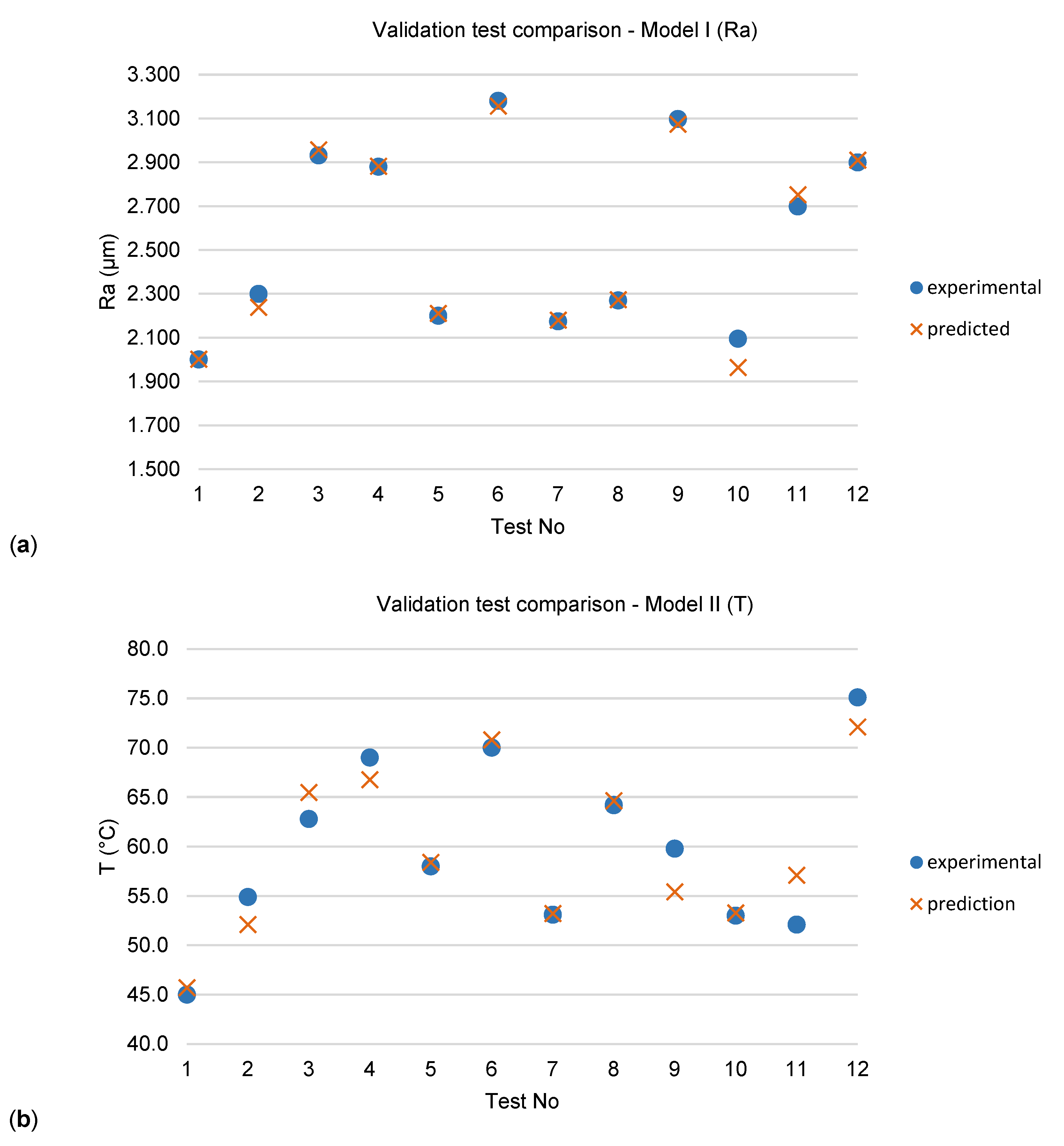
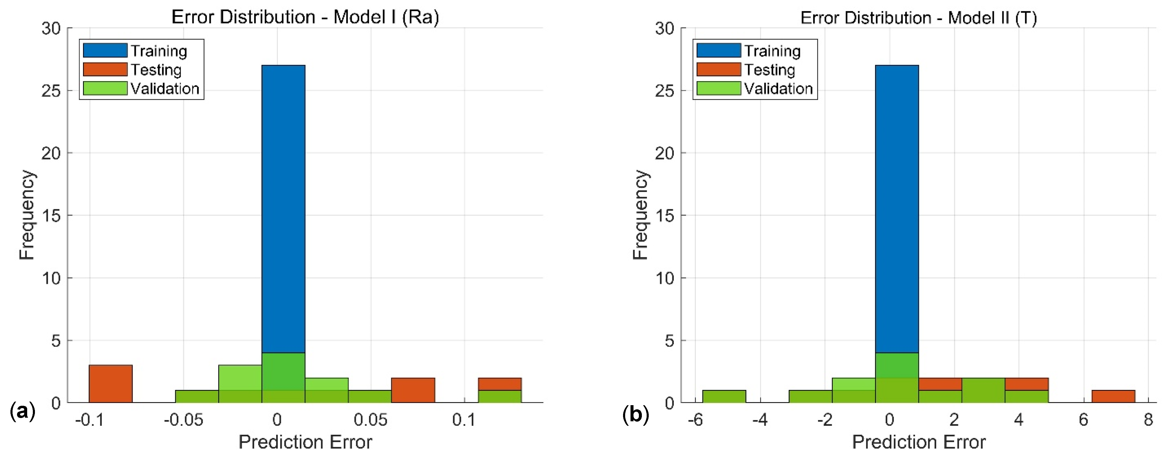
4.2. Performance Evaluation and Validation of the ANFIS Models

To validate the performance of the developed models, an extra set of 12 experiments was carried out. Table 4 presents the different combinations of input parameters that were considered arbitrarily from within the limits of this study, covering, however, underrepresented regions within the studied bounds of conditions.
Validation results revealed high convergence between the experimental and the predicted values for both roughness and temperature, suggesting the robustness and high accuracy of the modeling procedure. Specifically, according to Figure 8a, the relative error for the first model was calculated to be less than 2% or −2% for most cases, with the exception of test number 10, where the error was computed close to 7%. In a similar way, Figure 8b compares the experimental temperature values with the predicted ones. It is shown that the errors vary between −8.8% and 7.9%.
Figure 9 illustrates the distribution of the summation of the errors for the two models, including all data sets. Figure 9a depicts the errors for the surface roughness prediction model, whereas Figure 9b is for the tool-tip temperature. It is evident that for both models, all errors related to the training process are within the central bin (close to zero error). The validation errors are well distributed between −0.05 and 0.05 error bins. Similarly, the testing errors are within a reasonable range from the zero-error bin, with the exception of three instances that are close to −0.1 and two instances that surpass the 0.1 limit. Likewise, the training error points for the temperature model are all gathered in the close-to-zero bin, as shown in Figure 8b. Both testing and validation error points are well distributed among the error bins, with only one instance from each data set being relatively far from the center.

4.3. Response Optimization with NSGA-II

Since Ra and T are related, both responses were taken into account to optimize the process. Tool-tip temperature affects tool wear, which eventually influences the surface quality. Therefore, the purpose is to minimize both responses. The NSGA-II algorithm was employed to achieve this goal because it is well-established for multi-objective optimization purposes [53,54,55] based on evolutionary principles. It is designed to find a set of Pareto-optimal solutions where improving one objective cannot be achieved without degrading another. NSGA-II works by evolving a population of solutions through selection, crossover, and mutation, just like a typical genetic algorithm. Key features include fast, non-dominated sorting to rank solutions based on Pareto dominance. Crowding distance to maintain diversity by preferring solutions in less crowded areas. And elitism, where the best solutions are selected and advanced to the next generation to ensure convergence.
NSGA-II is widely used in engineering design, including machining optimization, where trade-offs between multiple objectives like surface roughness and tool temperature are crucial. For this study, both the population and the maximum number of generations were set to 100. Additionally, stopping criteria were not used. Figure 10 depicts the plots derived from the optimization process. Specifically, Figure 10a illustrates the Pareto fronts of solutions for the dry cutting of reinforced PETG, whereas Figure 10b depict the different combinations that generated the specific front of solutions, suggesting that optimal surface roughness and temperatures are generated at cutting speeds between 100 m/min and 200 m/min, combined with low feeds below 0.6 mm/rev and depth-of-cuts close to 0.5 mm.

5. Conclusions

In this study, the CNC turning of 3D-printed reinforced PETG material was investigated through the development of two ANFIS models, one for predicting surface roughness and another for cutting tool-tip temperature. Both models were structured with a 3–3–3 Sugeno-type configuration, trained on 27 experiments, tested with 12, and validated using an additional 12 experiments. The models demonstrated strong predictive performance, with prediction errors being well distributed across the dataset, confirming their generalization capability. Summarizing, the following concluding remarks were drawn:
  • The trials for determining the most suitable structure for the models revealed R2 values equal to 0.9920 and 0.9598 for the roughness and temperature models, respectively.
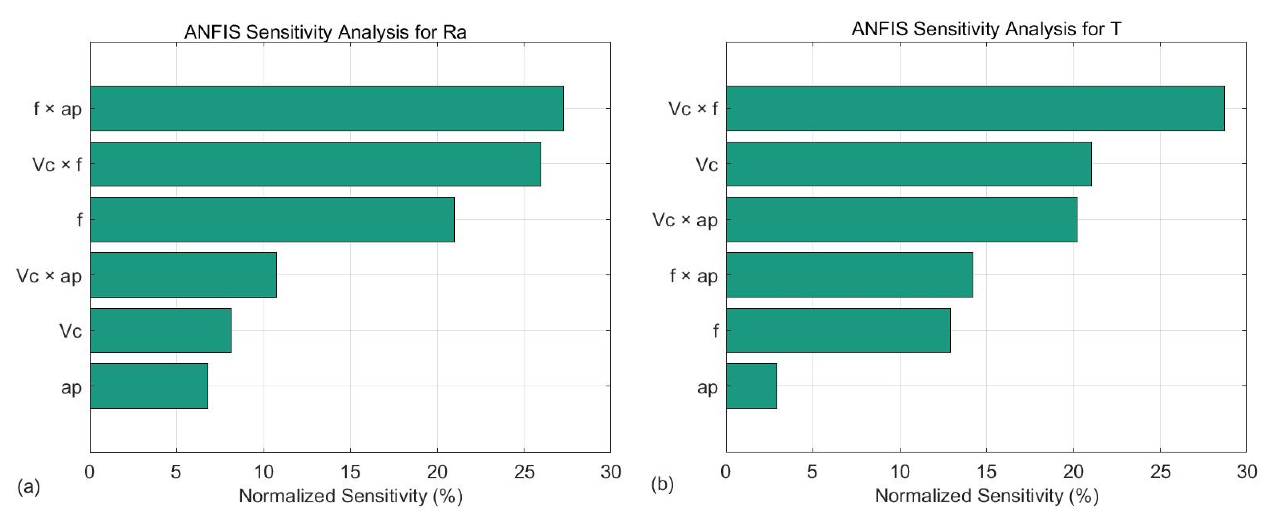
  • Sensitivity analysis revealed that feed rate and its interaction with depth-of-cut had the most pronounced influence on Ra, followed by the interaction of cutting speed × feed.
  • On the other hand, cutting speed and its interaction with feed were the most influential parameters affecting tool-tip temperature.
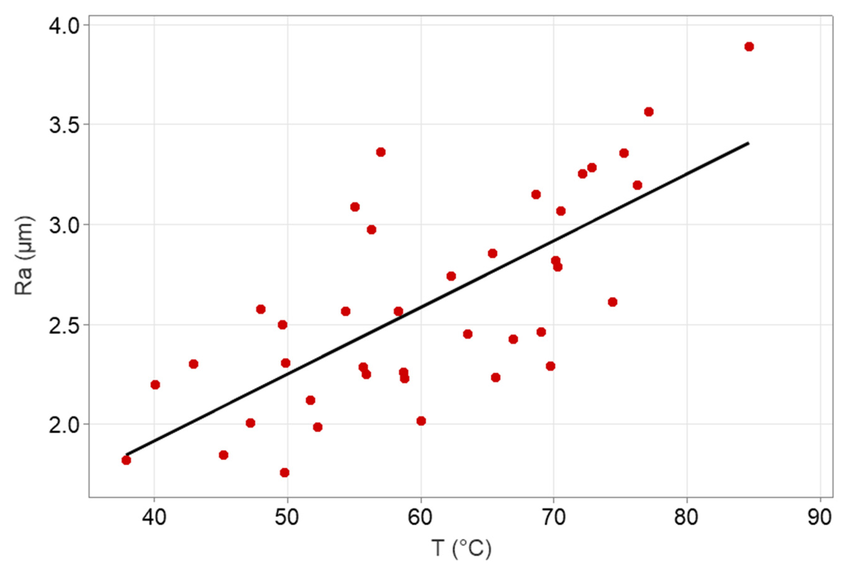
  • The interaction between Ra and T was further supported through a scatter plot, which highlighted a visible correlation, suggesting that conditions leading to lower Ra generally also resulted in reduced temperatures, though with some trade-offs.
  • Finally, multi-objective optimization using the NSGA-II algorithm provided a set of optimal machining conditions balancing both surface quality and thermal performance. The Pareto front indicated that cutting speeds between 100 and 200 m/min, combined with low feed rates (<0.6 mm/rev) and small depth-of-cut (~0.5 mm), lead to favorable machining outcomes. These results can guide the selection of cutting parameters for efficient and high-quality finishing turning operations of 3D-printed CFRP parts.

6. Future Work and Limitations

This study considers machining temperature as a response rather than as a dynamic input. Additionally, the model relies on continuous variables. Consequently, it does not have the ability to capture the changes that are related to the temperature and affect the surface quality. Future work will process the acquired measurements so that they can be implemented into the model. The aim is to develop a dynamic prediction system that can be linked to a digital twin.

Author Contributions

Conceptualization, A.T. and P.K.; Methodology, A.T.; Software, A.T.; Validation, A.T., D.N., S.-N.M. and P.K.; Formal analysis, A.T., D.N., S.-N.M. and P.K.; Investigation, A.T.; Resources, P.K.; Data curation, A.T., D.N., S.-N.M. and P.K.; Writing—original draft, A.T.; Writing—review & editing, A.T., D.N., S.-N.M. and P.K.; Visualization, A.T.; Supervision, A.T. and P.K.; Project administration, A.T. and P.K.; Funding acquisition, A.T. All authors have read and agreed to the published version of the manuscript.

Funding

This research received no external funding.

Data Availability Statement

Data presented in this study are available in this article.

Conflicts of Interest

The authors declare no conflicts of interest.

Abbreviations

The following abbreviations are used in this manuscript:
ANFISAdaptive Neuro-Fuzzy Inference System
CFRPCarbon-Fiber-Reinforced Polymer
GAGenetic Algorithm
MFMembership Function
NSGA-IINon-Dominated Sorting Genetic Algorithm 2
PETGPolyethylene Terephthalate Glycol

References

  1. Nowakowski, Ł.; Bartoszuk, M.; Skrzyniarz, M.; Błasiak, S.; Vasileva, D. Influence of the Milling Conditions of Aluminium Alloy 2017A on the Surface Roughness. Materials 2022, 15, 3626. [Google Scholar] [CrossRef] [PubMed]
  2. Bektaş, B.S.; Samtaş, G. Optimisation of Cutting Parameters in Face Milling of Cryogenic Treated 6061 Aluminium Alloy and Effects on Surface Roughness, Wear, and Cutting Temperatures. Surf. Topogr. Metrol. Prop. 2022, 10, 025013. [Google Scholar] [CrossRef]
  3. Uzun, M.; Usca, Ü.A.; Kuntoğlu, M.; Gupta, M.K. Influence of Tool Path Strategies on Machining Time, Tool Wear, and Surface Roughness During Milling of AISI X210Cr12 Steel. Int. J. Adv. Manuf. Technol. 2022, 119, 2709–2720. [Google Scholar] [CrossRef]
  4. Zhang, T.; Yuan, L. Understanding Surface Roughness on Vertical Surfaces of 316 L Stainless Steel in Laser Powder Bed Fusion Additive Manufacturing. Powder Technol. 2022, 411, 117957. [Google Scholar] [CrossRef]
  5. Alam, S.T.; Tomal, A.N.M.A.; Nayeem, M.K. High-Speed Machining of Ti–6Al–4V: RSM-GA Based Optimization of Surface Roughness and MRR. Results Eng. 2023, 17, 100873. [Google Scholar] [CrossRef]
  6. Imani, L.; Henzaki, A.R.; Hamzeloo, R.; Davoodi, B. Modeling and Optimizing of Cutting Force and Surface Roughness in Milling Process of Inconel 738 Using Hybrid ANN and GA. Proc. Inst. Mech. Eng. Part B J. Eng. Manuf. 2020, 234, 920–932. [Google Scholar] [CrossRef]
  7. Danish, M.; Gupta, M.K.; Ghazali, S.M.; Rathore, M.F.; Krolczyk, G.M.; Alsaady, A. Tool Wear and Surface Roughness Characteristics in Sustainable Machining of Additively Manufactured Titanium Alloys. J. Mater. Res. Technol. 2024, 30, 2955–2967. [Google Scholar] [CrossRef]
  8. Rajput, S.S.; Upadhyay, C.; Gangopadhyay, S.; Fernandes, F. Effects of Roughing, Finishing, and Aggressive Machining Conditions on the Milling Performance of AISI 1045 Steel Using TiAlN Coated Inserts. Proc. Inst. Mech. Eng. Part B 2023, 239, 376–387. [Google Scholar] [CrossRef]
  9. Sredanovic, B.; Cica, D.; Borojevic, S.; Tesic, S.; Kramar, D. Optimization of Superalloy Inconel 718 Micro-Milling Process by Combined Taguchi and Multi-Criteria Decision Making Method. J. Braz. Soc. Mech. Sci. Eng. 2024, 46, 423. [Google Scholar] [CrossRef]
  10. Lotfi, M.; Amini, S.; Akbari, J. Surface Integrity and Microstructure Changes in 3D Elliptical Ultrasonic Assisted Turning of Ti–6Al–4V: FEM and Experimental Examination. Tribol. Int. 2020, 151, 106492. [Google Scholar] [CrossRef]
  11. Saez-de-Buruaga, M.; Soler, D.; Aristimuño, P.X.; Esnaola, J.A.; Arrazola, P.J. Determining Tool/Chip Temperatures from Thermography Measurements in Metal Cutting. Appl. Therm. Eng. 2018, 145, 305–314. [Google Scholar] [CrossRef]
  12. Sambruno, A.; Gómez-Parra, Á.; Márquez, P.; Tellaeche-Herrera, I.; Batista, M. Evaluation of Peripheral Milling and Abrasive Water Jet Cutting in CFRP Manufacturing: Analysis of Defects and Surface Quality. Fibers 2024, 12, 78. [Google Scholar] [CrossRef]
  13. Tzotzis, A.; Nedelcu, D.; Mazurchevici, S.N.; Kyratsis, P. Surface Quality Evaluation of 3D-Printed Carbon-Fiber-Reinforced PETG Polymer During Turning: Experimental Analysis, ANN Modeling and Optimization. Polymers 2024, 16, 2927. [Google Scholar] [CrossRef] [PubMed]
  14. Molina-Moya, M.Á.; García-Martínez, E.; Miguel, V.; Coello, J.; Martínez-Martínez, A. Experimental Analysis and Application of a Multivariable Regression Technique to Define the Optimal Drilling Conditions for Carbon Fiber Reinforced Polymer (CFRP) Composites. Polymers 2023, 15, 3710. [Google Scholar] [CrossRef]
  15. Song, Y.; Cao, H.; Wang, Q.; Zhang, J.; Yan, C. Surface Roughness Prediction Model in High-Speed Dry Milling CFRP Considering Carbon Fiber Distribution. Compos. Part B Eng. 2022, 245, 110230. [Google Scholar] [CrossRef]
  16. Doluk, E.; Rudawska, A.; Kuczmaszewski, J.; Miturska-Barańska, I. Surface Roughness After Milling of the Al/CFRP Stacks with a Diamond Tool. Materials 2021, 14, 6835. [Google Scholar] [CrossRef]
  17. Arhamnamazi, S.; Aymerich, F.; Buonadonna, P.; El Mehtedi, M.; Taheri, H. Application of Central Composite Design in the Drilling Process of Carbon Fiber-Reinforced Polymer Composite. Appl. Sci. 2024, 14, 7610. [Google Scholar] [CrossRef]
  18. Popan, I.A.; Bocăneț, V.I.; Softic, S.; Popan, A.I.; Panc, N.; Balc, N. Artificial Intelligence Model Used for Optimizing Abrasive Water Jet Machining Parameters to Minimize Delamination in Carbon Fiber-Reinforced Polymer. Appl. Sci. 2024, 14, 8512. [Google Scholar] [CrossRef]
  19. Lalegani Dezaki, M.; Mohd Ariffin, M.K.A. Post-Processing of FDM 3D-Printed Polylactic Acid Parts by CNC Trimming. In Fused Deposition Modeling Based 3D Printing; Dave, H.K., Davim, J.P., Eds.; Springer International Publishing: Cham, Switzerland, 2021; pp. 195–212. ISBN 978-3-030-68024-4. [Google Scholar]
  20. Rabalo, M.A.; Rubio, E.M.; Agustina, B.; Camacho, A.M. Hybrid Additive and Subtractive Manufacturing: Evolution of the Concept and Last Trends in Research and Industry. Procedia CIRP 2023, 118, 741–746. [Google Scholar] [CrossRef]
  21. Tamburrino, F.; Barone, S.; Paoli, A.; Razionale, A.V. Post-Processing Treatments to Enhance Additively Manufactured Polymeric Parts: A Review. Virtual Phys. Prototyp. 2021, 16, 218–251. [Google Scholar] [CrossRef]
  22. Gómez-García, D.; Díaz-Álvarez, A.; Youssef, G.; Miguélez, H.; Díaz-Álvarez, J. Machinability of 3D Printed Peek Reinforced with Short Carbon Fiber. Compos. Part C Open Access 2023, 12, 100387. [Google Scholar] [CrossRef]
  23. El Mehtedi, M.; Buonadonna, P.; Loi, G.; El Mohtadi, R.; Carta, M.; Aymerich, F. Surface Quality Related to Face Milling Parameters in 3D Printed Carbon Fiber-Reinforced PETG. J. Compos. Sci. 2024, 8, 128. [Google Scholar] [CrossRef]
  24. Ma, C.K.; Aguilar, L.; Karim, M.; Abdun Nafi, M.; Ma, J.; Jahan, M.P. Experimental Investigation of Nanosecond Laser Machining of 3D Printed Carbon Fiber Reinforced Polymer (CFRP) Composite. Manuf. Lett. 2023, 35, 399–409. [Google Scholar] [CrossRef]
  25. Cococcetta, N.; Jahan, M.P.; Schoop, J.; Ma, J.; Pearl, D.; Hassan, M. Post-Processing of 3D Printed Thermoplastic CFRP Composites Using Cryogenic Machining. J. Manuf. Process. 2021, 68, 332–346. [Google Scholar] [CrossRef]
  26. Hassan, M.; Ma, J.; Jahan, M.P. Numerical Modeling and Simulation of Machining of 3D Printed CFRP Composite. Manuf. Lett. 2022, 33, 415–427. [Google Scholar] [CrossRef]
  27. Tzotzis, A.; Maropoulos, P.; Kyratsis, P. A Dynamic Surface Roughness Prediction System Based on Machine Learning for the 3D-Printed Carbon-Fiber-Reinforced-Polymer (CFRP) Turning. J. Intell. Manuf. 2025, 7075. [Google Scholar] [CrossRef]
  28. Song, Y.; Cao, H.; Zheng, W.; Qu, D.; Liu, L.; Yan, C. Cutting Force Modeling of Machining Carbon Fiber Reinforced Polymer (CFRP) Composites: A Review. Compos. Struct. 2022, 299, 116096. [Google Scholar] [CrossRef]
  29. Ko, J.H.; Yin, C. A Review of Artificial Intelligence Application for Machining Surface Quality Prediction: From Key Factors to Model Development. J. Intell. Manuf. 2025. [Google Scholar] [CrossRef]
  30. Agu, C.M.; Ani, K.A.; Ani, O.N.; Nnaji, P.C.; Kadurumba, C.H.; Esonye, C. Application of Efficient Soft Computing Approaches for Modeling Methyl Ester Yield from Azadirachta Indica (Neem) Seed Oil: A Comparative Study of RSM, ANN and ANFIS. Green Technol. Sustain. 2024, 2, 100057. [Google Scholar] [CrossRef]
  31. Akhil, C.S.; Ananthavishnu, M.H.; Akhil, C.K.; Afeez, P.M.; Rahul, R. Measurement of Cutting Temperature During Machining. IOSR J. Mech. Civ. Eng. 2016, 13, 108–122. [Google Scholar] [CrossRef]
  32. Kohli, A.; Dixit, U.S. A Neural-Network-Based Methodology for the Prediction of Surface Roughness in a Turning Process. Int. J. Adv. Manuf. Technol. 2005, 25, 118–129. [Google Scholar] [CrossRef]
  33. Tzotzis, A.; Efkolidis, N.; Cheng, K.; Kyratsis, P. Multiple Regression Analysis and Non-Dominated Sorting Genetic Algorithm II Optimization of Machining Carbon-Fiber-Reinforced Polyethylene Terephthalate Glycol Parts Fabricated via Additive Manufacturing Under Dry and Lubricated Conditions. Lubricants 2025, 13, 63. [Google Scholar] [CrossRef]
  34. Vallejo, J.; García-Plaza, E.; Núñez, P.J.; Chacón, J.M.; Caminero, M.A.; Romero, A. Machinability Analysis of Carbon Fibre Reinforced PET-Glycol Composites Processed by Additive Manufacturing. Compos. Part A Appl. Sci. Manuf. 2023, 172, 107561. [Google Scholar] [CrossRef]
  35. Das, S.R.; Dhupal, D.; Kumar, A. Experimental Investigation into Machinability of Hardened AISI 4140 Steel Using TiN Coated Ceramic Tool. Meas. J. Int. Meas. Confed. 2015, 62, 108–126. [Google Scholar] [CrossRef]
  36. Abhishek, K.; Datta, S.; Mahapatra, S.S. Optimization of MRR, Surface Roughness, and Maximum Tool-Tip Temperature During Machining of CFRP Composites. Mater. Today Proc. 2017, 4, 2761–2770. [Google Scholar] [CrossRef]
  37. Marani, M.; Songmene, V.; Zeinali, M.; Kouam, J.; Zedan, Y. Neuro-Fuzzy Predictive Model for Surface Roughness and Cutting Force of Machined Al–20 Mg2Si–2Cu Metal Matrix Composite Using Additives. Neural Comput. Appl. 2020, 32, 8115–8126. [Google Scholar] [CrossRef]
  38. Srivastava, A.K.; Mofakkirul Islam, M. Prediction of Tool Wear and Surface Finish Using ANFIS Modelling During Turning of Carbon Fiber Reinforced Plastic (CFRP) Composites. Manuf. Lett. 2024, 41, 658–669. [Google Scholar] [CrossRef]
  39. Siva Kumar, M.; Rajamani, D.; El-Sherbeeny, A.M.; Balasubramanian, E.; Karthik, K.; Hussein, H.M.A.; Astarita, A. Intelligent Modeling and Multi-Response Optimization of AWJC on Fiber Intermetallic Laminates Through a Hybrid ANFIS-Salp Swarm Algorithm. Materials 2022, 15, 7216. [Google Scholar] [CrossRef]
  40. Benkhelladi, A.; Laouissi, A.; Laouici, H.; Bouchoucha, A.; Karmi, Y.; Chetbani, Y. Assessment of Hybrid Composite Drilling and Prediction of Cutting Parameters by ANFIS and Deep Neural Network Approach. Int. J. Adv. Manuf. Technol. 2024, 135, 589–606. [Google Scholar] [CrossRef]
  41. Jang, J.-S.R. ANFIS: Adaptive-Network-Based Fuzzy Inference System. IEEE Trans. Syst. Man. Cybern. 1993, 23, 665–685. [Google Scholar] [CrossRef]
  42. Takagi, T.; Sugeno, M. Fuzzy Identification of Systems and Its Applications to Modeling and Control. IEEE Trans. Syst. Man. Cybern. 1985, SMC-15, 116–132. [Google Scholar] [CrossRef]
  43. Sada, S.O.; Ikpeseni, S.C. Evaluation of ANN and ANFIS Modeling Ability in the Prediction of AISI 1050 Steel Machining Performance. Heliyon 2021, 7, e06136. [Google Scholar] [CrossRef]
  44. El Mehtedi, M.; Buonadonna, P.; El Mohtadi, R.; Aymerich, F.; Carta, M. Surface Quality Related to Machining Parameters in 3D-Printed PETG Components. Procedia Comput. Sci. 2024, 232, 1212–1221. [Google Scholar] [CrossRef]
  45. Maier, R.; Bucaciuc, S.G.; Mandoc, A.C. Reducing Surface Roughness of 3D Printed Short-Carbon Fiber Reinforced Composites. Materials 2022, 15, 7398. [Google Scholar] [CrossRef] [PubMed]
  46. Parandoush, P.; Deines, T.; Lin, D.; Zhang, H.; Ye, C. Mechanical Finishing of 3D Printed Continuous Carbon Fiber Reinforced Polymer Composites via CNC Machining. In Proceedings of the Volume 1: Additive Manufacturing; Manufacturing Equipment and Systems; Bio and Sustainable Manufacturing; American Society of Mechanical Engineers: New York, NY, USA, 2019. [Google Scholar]
  47. Ginoux, G.; Paux, J.; Allaoui, S. New Preparation Method of Microstructurally and Mechanically Standardized PETG Specimens by Material Extrusion Additive Manufacturing and Machining. Addit. Manuf. 2023, 66, 103471. [Google Scholar] [CrossRef]
  48. El Mehtedi, M.; Buonadonna, P.; El Mohtadi, R.; Loi, G.; Aymerich, F.; Carta, M. Optimizing Milling Parameters for Enhanced Machinability of 3D-Printed Materials: An Analysis of PLA, PETG, and Carbon-Fiber-Reinforced PETG. J. Manuf. Mater. Process. 2024, 8, 131. [Google Scholar] [CrossRef]
  49. Venkatesh, R.; Kathiravan, S.; Prabhakaran, R.; Ramar, M.; Jerold John Britto, J.; Rajakarunakaran, S. Experimental Investigation on Machinability of Additive Manufactured PLA and PETG Polymers Under Dry Turning Process BT—Recent Advances in Materials Technologies; Rajkumar, K., Jayamani, E., Ramkumar, P., Eds.; Springer Nature: Singapore, 2023; pp. 553–561. [Google Scholar]
  50. Tezel, T. The Effect of Machining Parameters on the Surface Quality of 3D Printed and Cast Polyamide. Mach. Sci. Technol. 2021, 25, 703–720. [Google Scholar] [CrossRef]
  51. Rawal, S.; Sidpara, A.M.; Paul, J. A Review on Micro Machining of Polymer Composites. J. Manuf. Process. 2022, 77, 87–113. [Google Scholar] [CrossRef]
  52. Dilberoglu, U.M.; Yaman, U.; Dolen, M. A Comprehensive Guide to Milling Techniques for Smoothing the Surfaces of 3D-Printed Thermoplastic Parts. Rapid Prototyp. J. 2024, 30, 1648–1662. [Google Scholar] [CrossRef]
  53. Wang, Q.; Jia, X. Optimization of Cutting Parameters for Improving Exit Delamination, Surface Roughness, and Production Rate in Drilling of CFRP Composites. Int. J. Adv. Manuf. Technol. 2021, 117, 3487–3502. [Google Scholar] [CrossRef]
  54. Zeelanbasha, N.; Senthil, V.; Mahesh, G. A Hybrid Approach of NSGA-II and TOPSIS for Minimising Vibration and Surface Roughness in Machining Process. Int. J. Oper. Res. 2020, 38, 221–254. [Google Scholar] [CrossRef]
  55. Sen, B.; Kumar, R.; Kanabar, B.; Kedia, A.; Kumar, A.V.; Bhowmik, A. Comparative Analysis of NSGA-II and TLBO for Optimizing Machining Parameters of Inconel 690: A Sustainable Manufacturing Paradigm. J. Mater. Eng. Perform. 2024. [Google Scholar] [CrossRef]
Figure 1. The experimental setup, tools, and methodologies used in this study.
Applsci 15 05373 g001
Figure 2. The geometry of the specimens (a) and sample 3D-printed workpieces (b).
Applsci 15 05373 g002
Figure 3. Probability plot of the experimental surface roughness (a) and the cutting temperature (b).
Applsci 15 05373 g003
Figure 4. Scatterplot for the correlation between the measured surface roughness and the temperature.
Applsci 15 05373 g004
Figure 5. The selected structure of the proposed ANFIS model.
Applsci 15 05373 g005
Figure 6. The surface plots of the responses in relation to the input combinations: Vc–f for Ra (a), Vc–ap for Ra (b), ap–f for Ra (c), Vc–f for T (d), Vc–ap for T (e), and ap–f for T (f).
Applsci 15 05373 g006
Figure 7. The sensitivity analysis plots for Ra (a) and T (b).
Applsci 15 05373 g007
Figure 8. Validation test comparison for Models I (a) and II (b).
Applsci 15 05373 g008
Figure 9. Error distribution for Models I (a) and II (b).
Applsci 15 05373 g009
Figure 10. The Pareto front of solutions (a) and the corresponding solutions with respect to the input parameters (b).
Applsci 15 05373 g010
Table 1. Settings for fabricating the workpieces using the FFF method.
SettingValue
Printing Nozzle temperature255 °C
Plate temperature70 °C
Filament1.75 mm
Printing Nozzle diameter0.6 mm
Layer0.2 mm
Printing speed40 mm/s
Flow100%
Shell thickness3 mm
Table 2. The experimental results according to the training and testing data.
Experiment No.Vc
(m/min)
f
(mm/rev)
ap
(mm)
Ra
(μm)
T
(°C)
Training Data11150.050.501.82337.9
21150.051.252.19840.1
31150.052.002.30143.0
41150.080.502.00947.2
51150.081.252.58048.0
61150.082.002.30849.9
71150.110.502.56654.4
81150.111.253.09055.1
91150.112.003.36257.0
102000.050.501.76249.8
112000.051.251.98952.3
122000.052.002.25355.9
132000.080.502.02060.0
142000.081.252.74462.3
152000.082.002.46669.0
162000.110.502.78870.3
172000.111.253.06770.5
182000.112.003.25572.1
192850.050.502.12151.7
202850.051.252.26258.7
212850.052.002.45363.5
222850.080.502.42966.9
232850.081.253.28872.8
242850.082.002.61674.4
252850.110.503.19976.2
262850.111.253.56677.1
272850.112.003.89084.6
Testing Data281500.060.751.85045.2
291750.091.502.89356.3
302250.071.752.29569.7
312500.061.002.23765.6
321300.071.502.32949.6
331850.100.902.85665.4
342600.071.302.93268.6
351450.090.602.25358.8
362100.061.602.28655.7
372700.090.802.82170.1
381900.071.102.47858.3
392400.101.403.35775.2
Table 3. Comparison of different ANFIS structures with respect to the MF number and type.
StructureRMSER2
MF NumberMF TypeModel IModel IIModel IModel II
2-2-2Triangular0.19322.60390.84380.9394
Trapezoidal0.21074.45520.81410.8226
Gaussian0.19063.04740.84780.9170
Generalized bell-shaped0.19533.49490.84040.8909
3-3-3Triangular0.04302.12230.99200.9598
Trapezoidal0.09622.95680.95830.9219
Gaussian0.09982.52420.96120.9431
Generalized bell-shaped0.10062.56790.95760.9411
4-4-4TriangularToo highToo highToo lowToo low
TrapezoidalToo highToo highToo lowToo low
GaussianToo highToo highToo lowToo low
Generalized bell-shaped0.2111Too high0.8134Too low
Table 4. Validation experiments with respect to the input combinations.
Test No.Vc (m/min)f (mm/rev)ap (mm)
11450.060.90
21650.071.00
31800.0951.75
42200.091.10
52450.0650.80
62600.0851.30
71750.061.60
82000.071.90
91250.101.40
102350.0550.70
111550.091.15
122700.081.60
Disclaimer/Publisher’s Note: The statements, opinions and data contained in all publications are solely those of the individual author(s) and contributor(s) and not of MDPI and/or the editor(s). MDPI and/or the editor(s) disclaim responsibility for any injury to people or property resulting from any ideas, methods, instructions or products referred to in the content.

