

Shear Properties and Failure Mechanism of Matched Discontinuities Between Two Different Rock Types Under Direct Shear


Abstract
1. Introduction
2. Specimen Preparation
2.1. Preparation of Rock and Rock-like Materials
- (1)
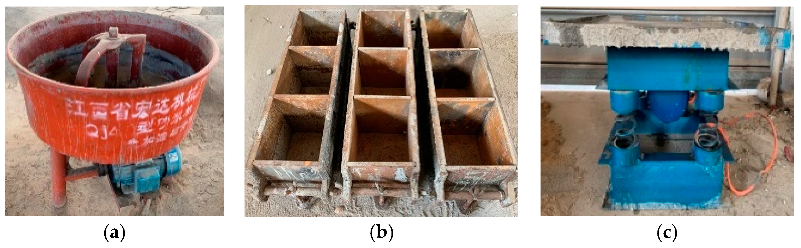
- Quartz sand and cement were mixed in an electric mixer according to the designed weight ratio (as shown in Figure 1a). To ensure the initial strength and fluidity of the model material, early water reducing agent with 0.5% cement mass was added, and the mixture was fully stirred for 2 min.
- (2)
- Water was poured into the mixer and fully stirred with the dry material for 2 min to obtain the mortar material.
- (3)
- Mortar specimens were prepared using a triple cast iron mold with dimensions of 300 mm × 100 mm × 100 mm (length × width × height) (see Figure 1b). In order to facilitate the demolding of the sample after curing, a layer of demolding agent was sprayed on the inner surface of the mold. The mold filled with mortar was placed on the low-frequency electric vibration table (see Figure 1c).
- (4)
- In order to obtain the basic physical and mechanical properties of the mortar material, cylindrical specimens with size of ϕ 50 mm × 100 mm (diameter × height) and size of ϕ 50 mm × 30 mm (diameter × height) were prepared. The mortar was slowly poured into the mold, and then the mold was vibrated on the vibration table for 3 min.
- (5)
- After all mortar specimens were cured for 24 h, the specimens were extracted from the mold and placed at indoor temperature of about 25 °C for 4 weeks.
2.2. Three-Dimensional Carving of Rough Joints
- (1)
- Generation of JRC profiles. Three curves with JRC of 2.8, 10.8 and 18.7 from the Barton joint profiles were taken as the prototype. The coordinate points of the selected joint profiles given by Li and Zhang [34] were employed and were imported into AutoCAD 2016 software such that three JRC curves with length of 100 mm were plotted with the spline curve command and saved in R50 format.
- (2)
- Three-dimensional stretching of Barton joint profiles. By employing JD Paint software, the three two-dimensional (2D) JRC curves obtained by step (1) were stretched 100 mm along the direction perpendicular to the extension direction. By doing that, three 3D surfaces with dimensions 100 mm × 100 mm were obtained.
- (3)
- Curving parameter setting of the engraving machine. The vertex of the lower left corner of each 3D stretching surface generated by step (2) was selected as the coordinate origin. The path spacing of the carving tool was set to 0.06 mm and a taper ball-end cutter with a diameter of 0.6 mm was installed as the carving tool. The tool path obtained by JD Paint software was transformed into a format that can be recognized by the engraving machine.
- (4)
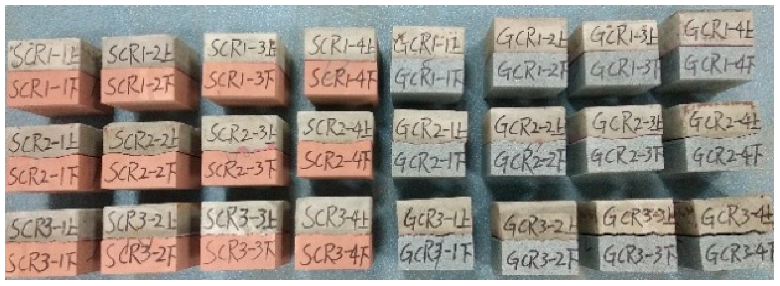
- Surface morphology carving of joints. The prepared rock and mortar specimens with size 100 mm × 100 mm × 50 mm (length × width × height) were firmly fixed on the bench clamp of the engraving machine. The origin of the carving path and the carving origin were calibrated. Subsequently, the engraving machine was operated to automatically engrave the surface morphology of joints according to the carving path assigned by step (3). Once the carving for one specimen was completed, the cutting tool path was rotated 180° and the matching specimen was carved by repeating the above process to gain a pair of joint blocks with identical morphology. Finally, a pair of fully mated rough joint specimens was obtained.
- (5)
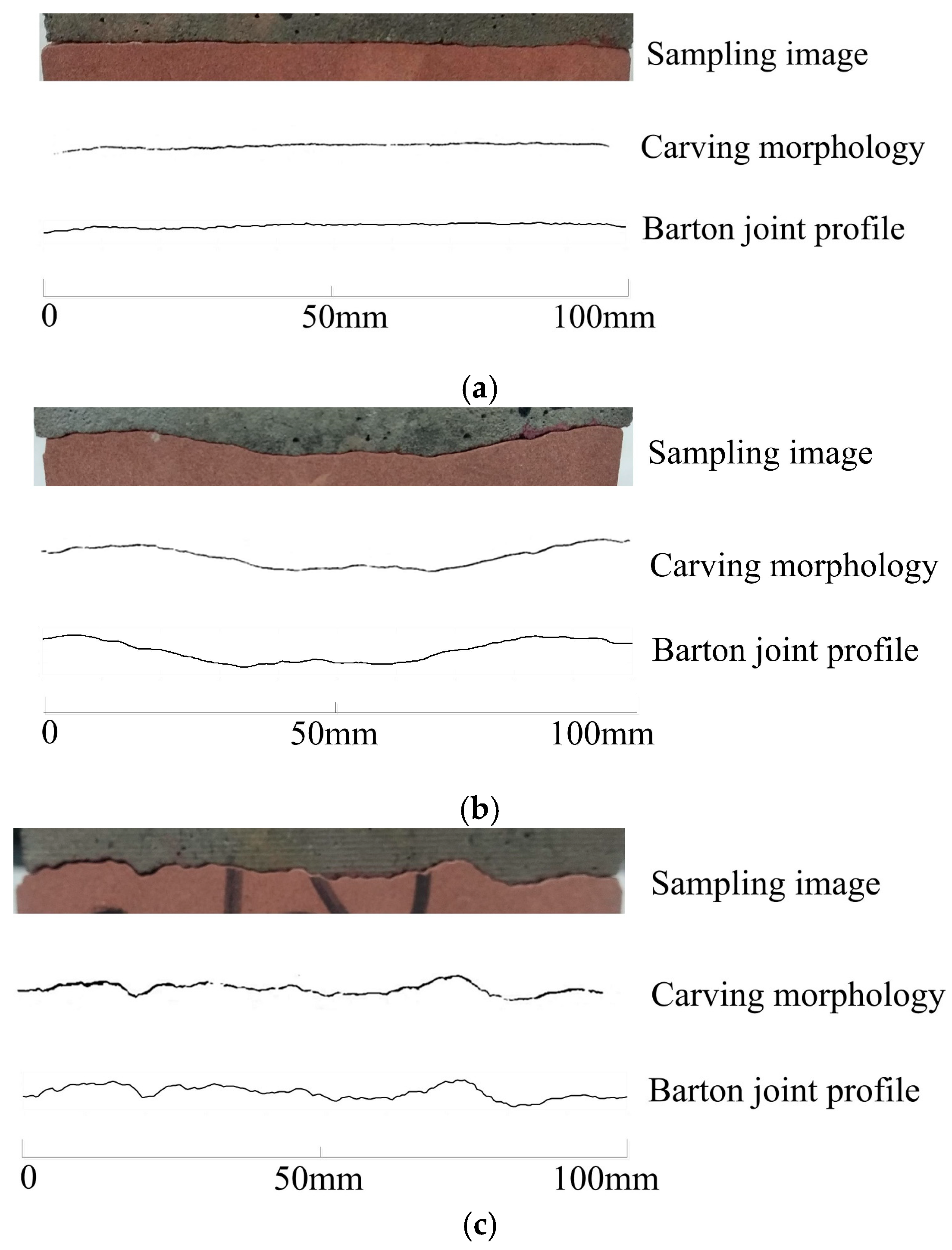
- Evaluation of the joint-engraving precision. After completing the engraving work of all rough joint specimens, the morphological information of the rough joint was extracted to estimate the carving precision. The image of joints with different joint wall materials was binarized by the image-editing software ImageJ v1.8.0 to obtain the gray image of the carving acquisition line of joint. The joint image and the carving morphology of the joint were compared with the Barton joint profile, as shown in Figure 3. It can be realized from Figure 3 that the carving morphologies of the joint are in good agreement with the Barton joint profiles, indicating that the 3D carving method is applicable to carve the rock and rock-like materials to obtain rock joint specimens with specific morphology in batches.
3. Experiment Scheme
3.1. Physical and Mechanical Properties of Materials
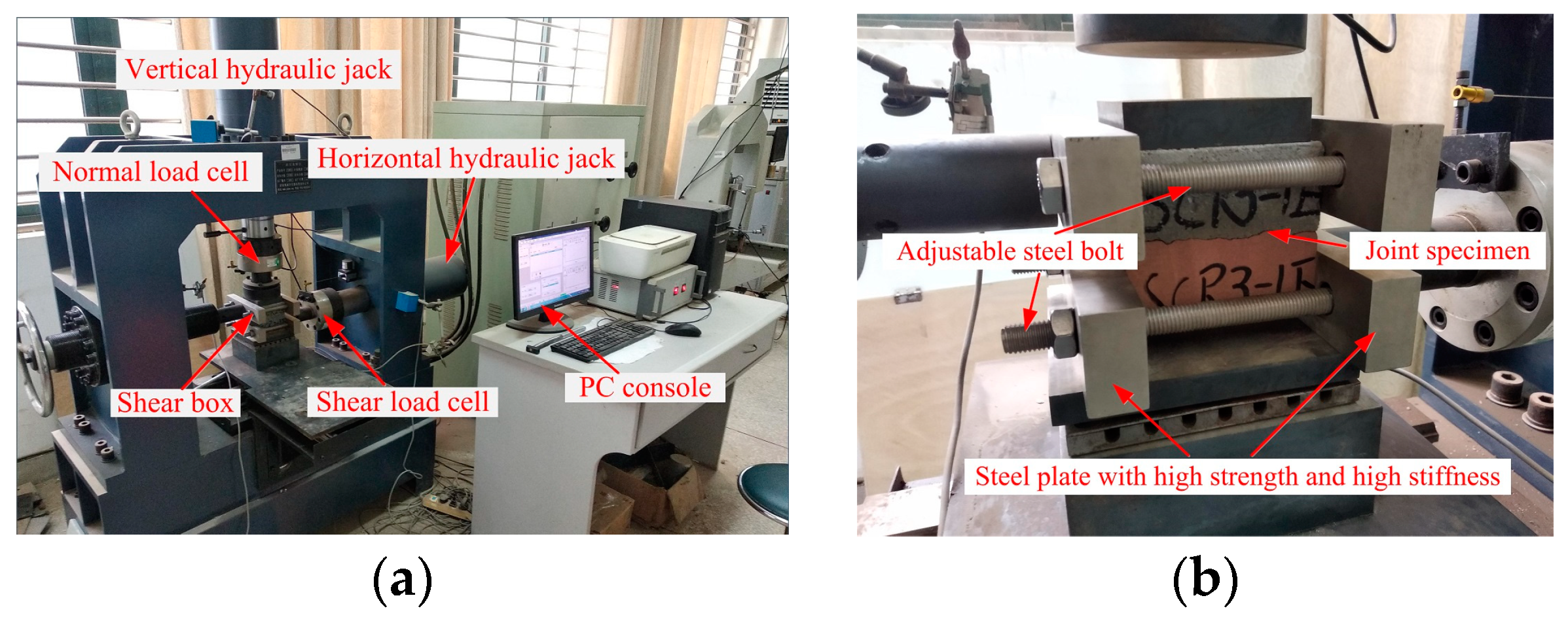
3.2. Shear Test Method
4. Experiment Results and Analyses
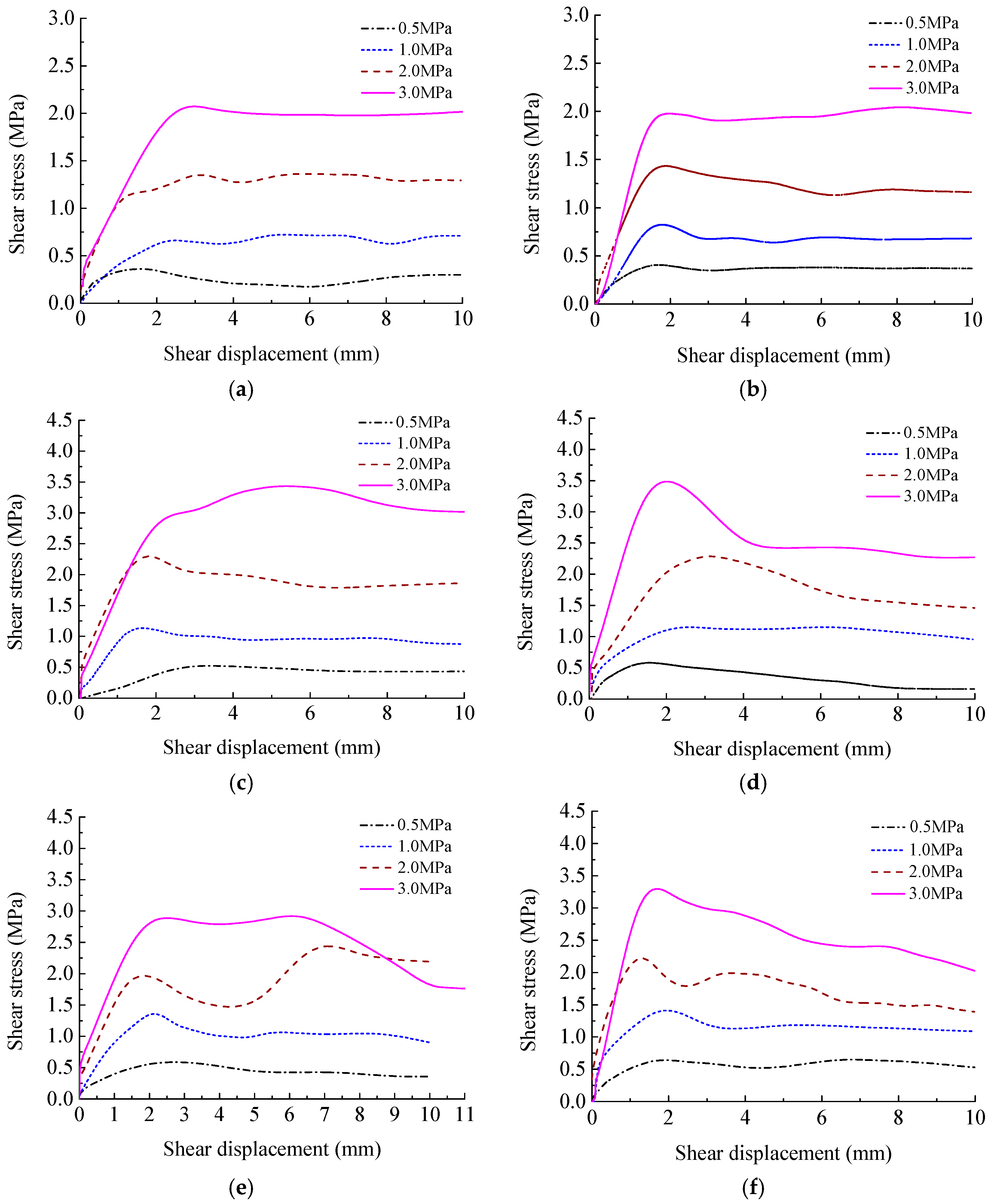
4.1. Shear Properties of Rough Discontinuities Possessing Different Joint Wall Strengths
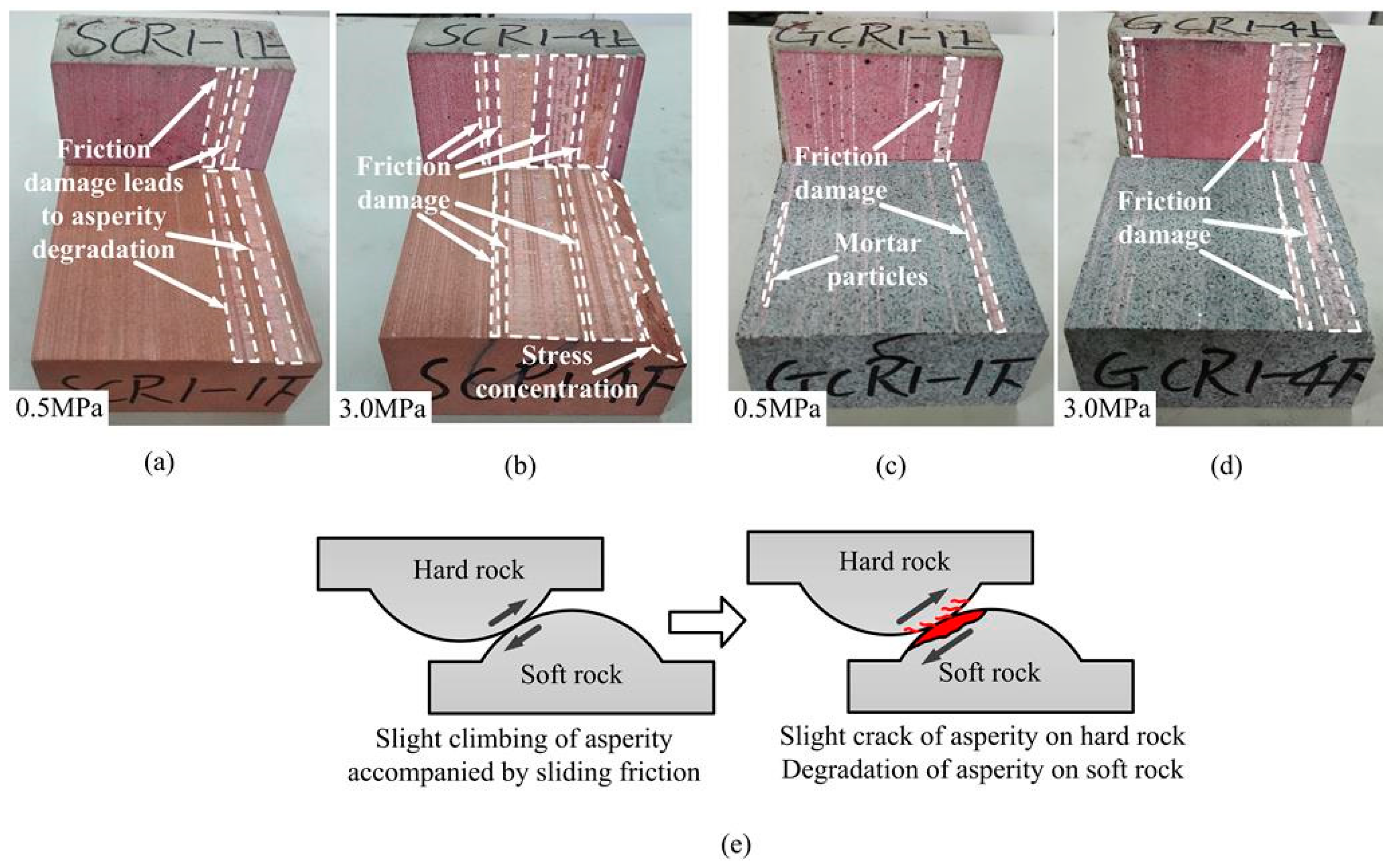
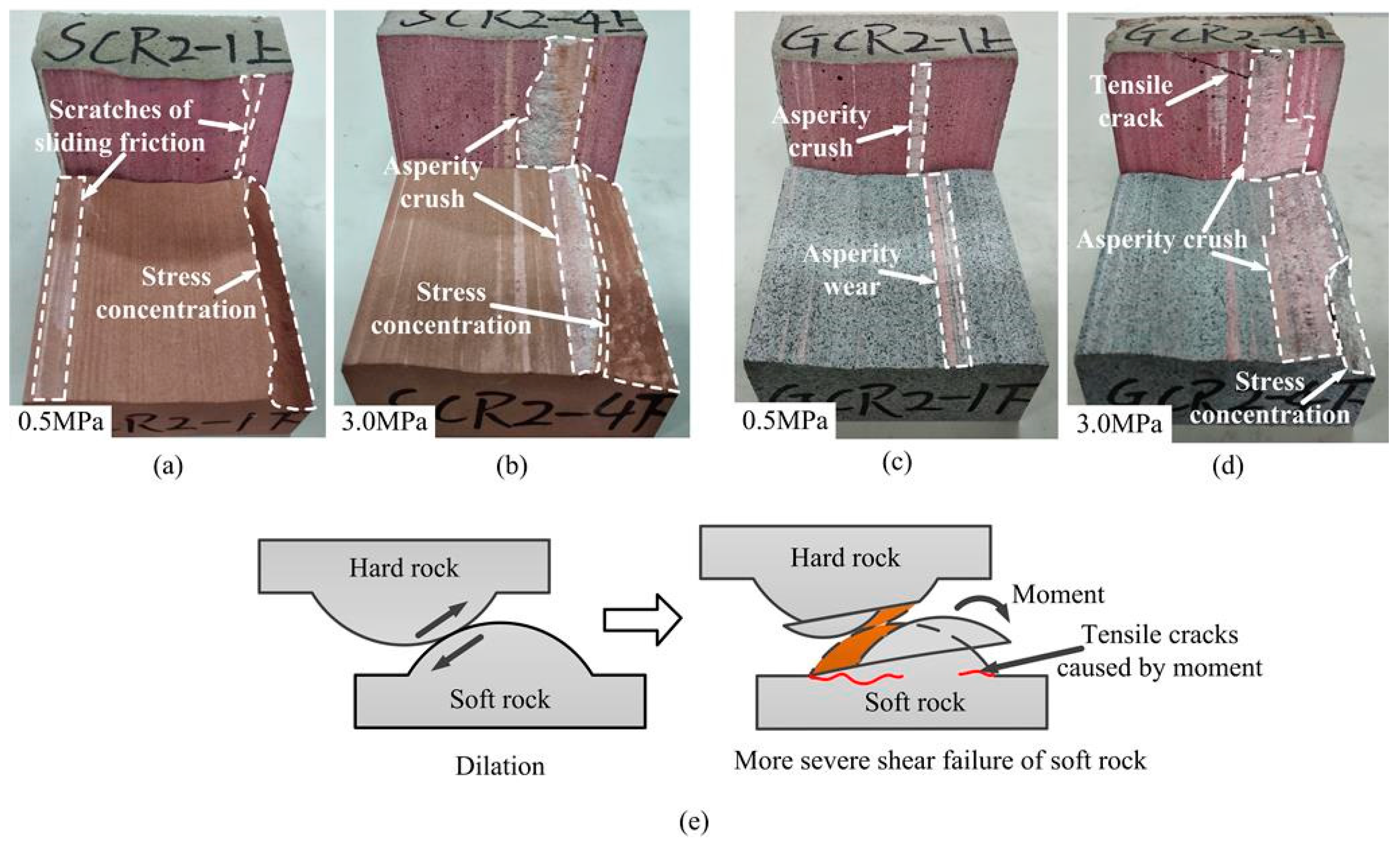
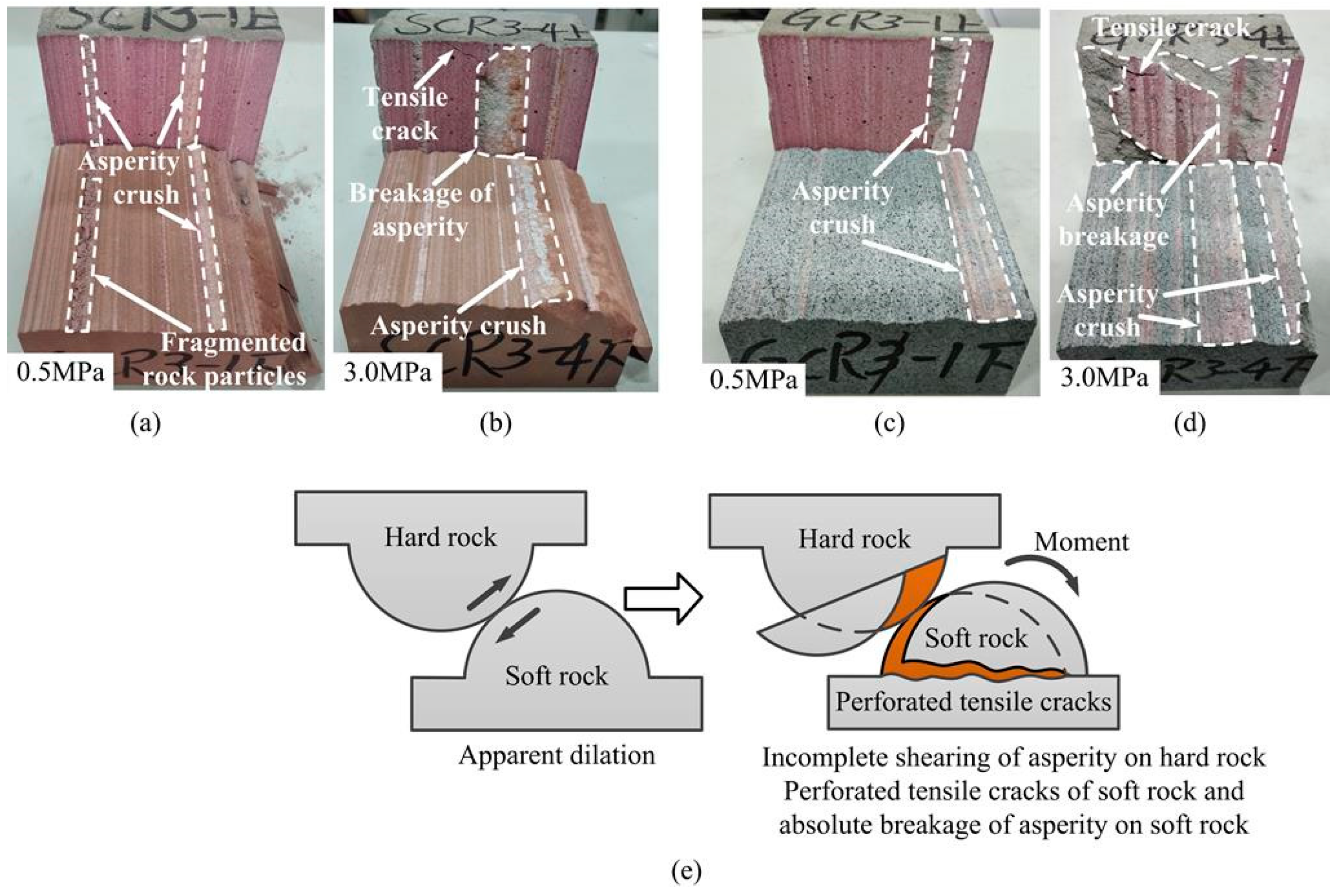
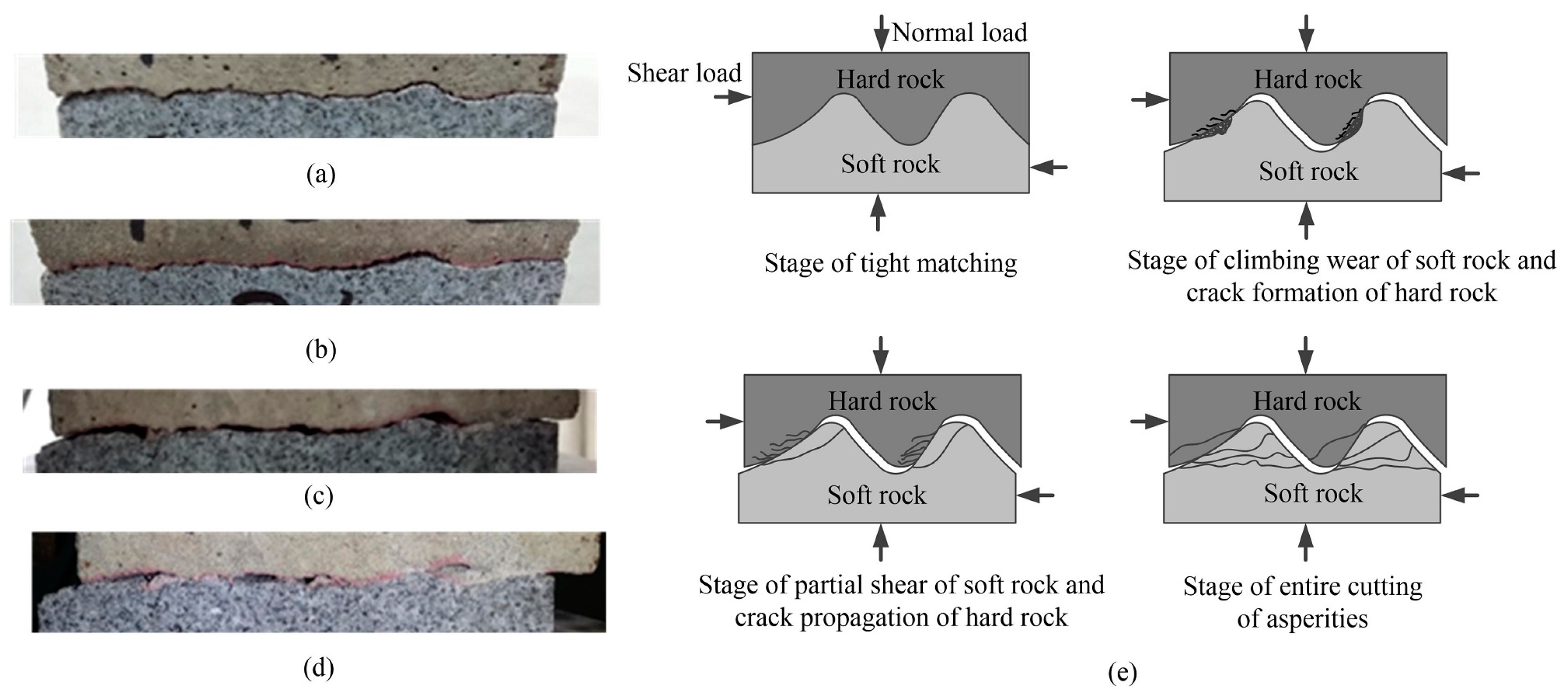
4.2. Failure Mechanism of Rough Discontinuities Possessing Different Joint Wall Strengths
5. Numerical Simulation of Shear Test of Discontinuities Possessing Different Joint Wall Strengths
5.1. Fundamental Introduction of UDEC
5.2. Determination of Constitutive Model and Its Parameters
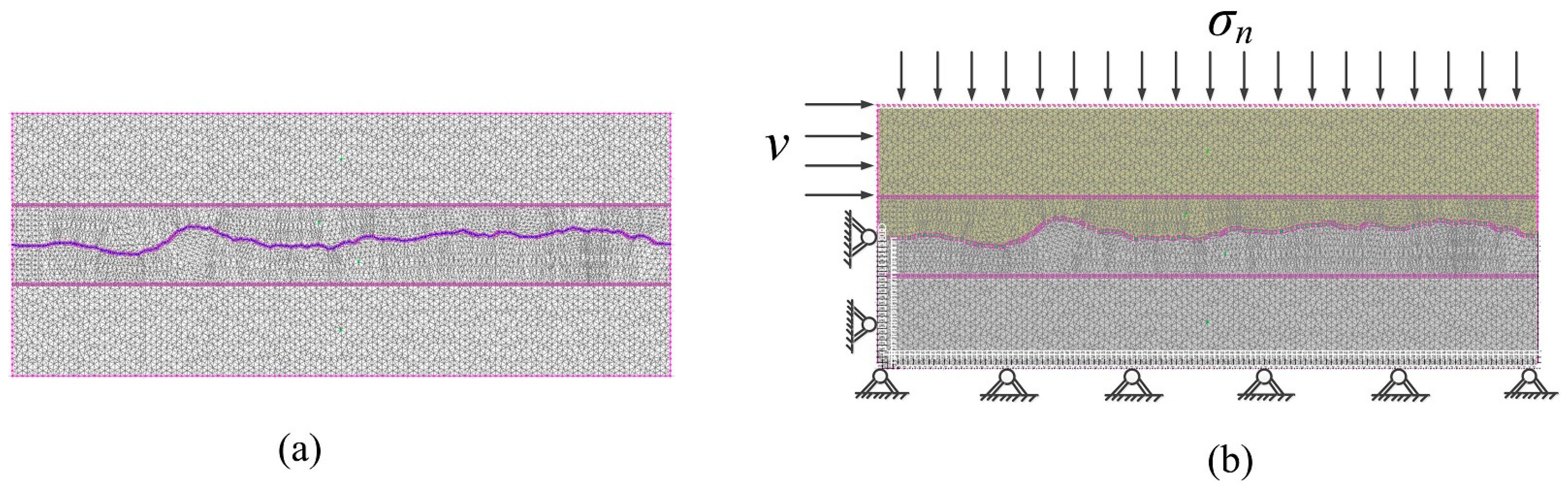
5.3. Establishment of Numerical Model of Shear Tests
6. Results and Analysis of Numerical Simulation
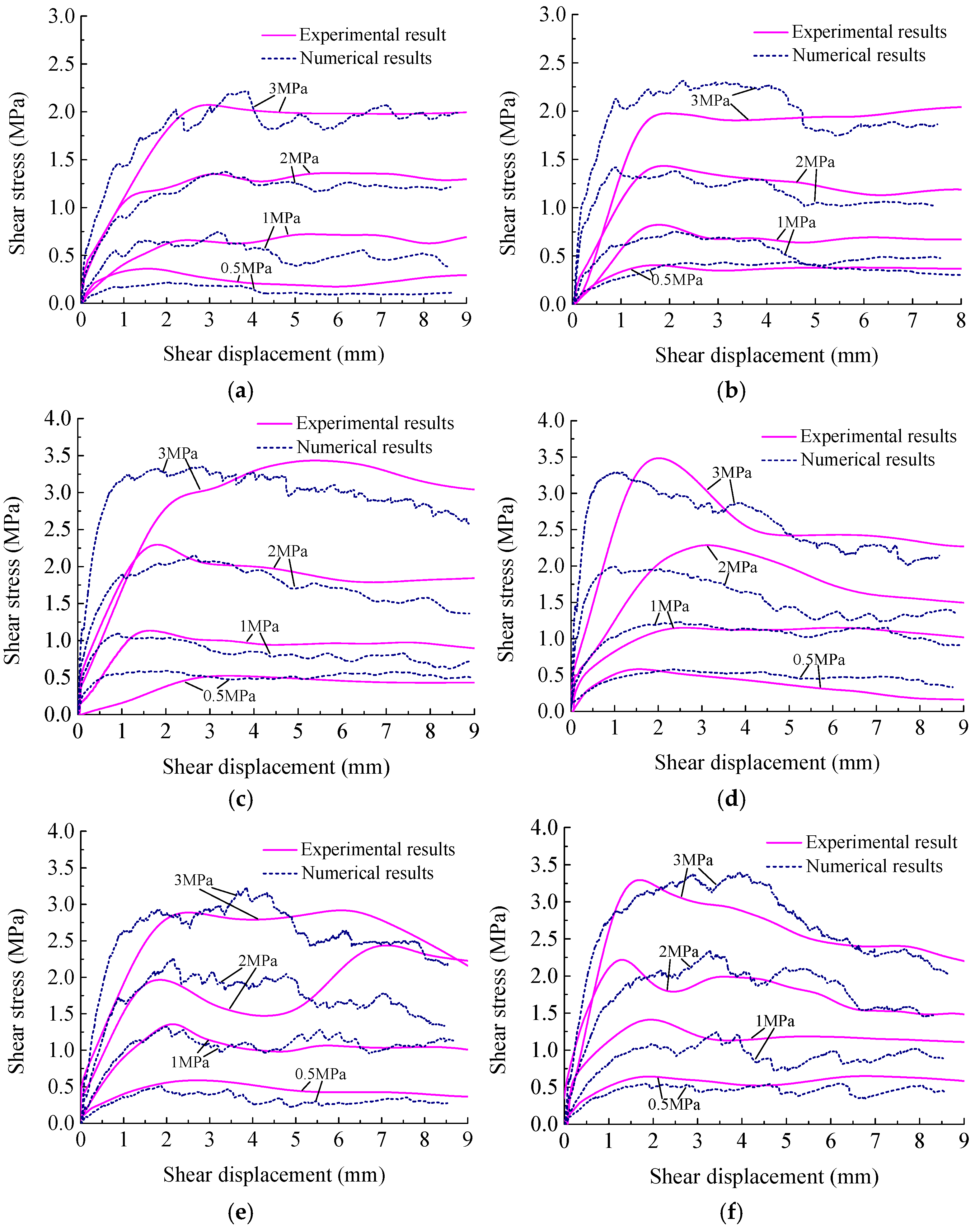
6.1. Numerical Shear Characteristic of Discontinuities Possessing Different Joint Wall Strengths
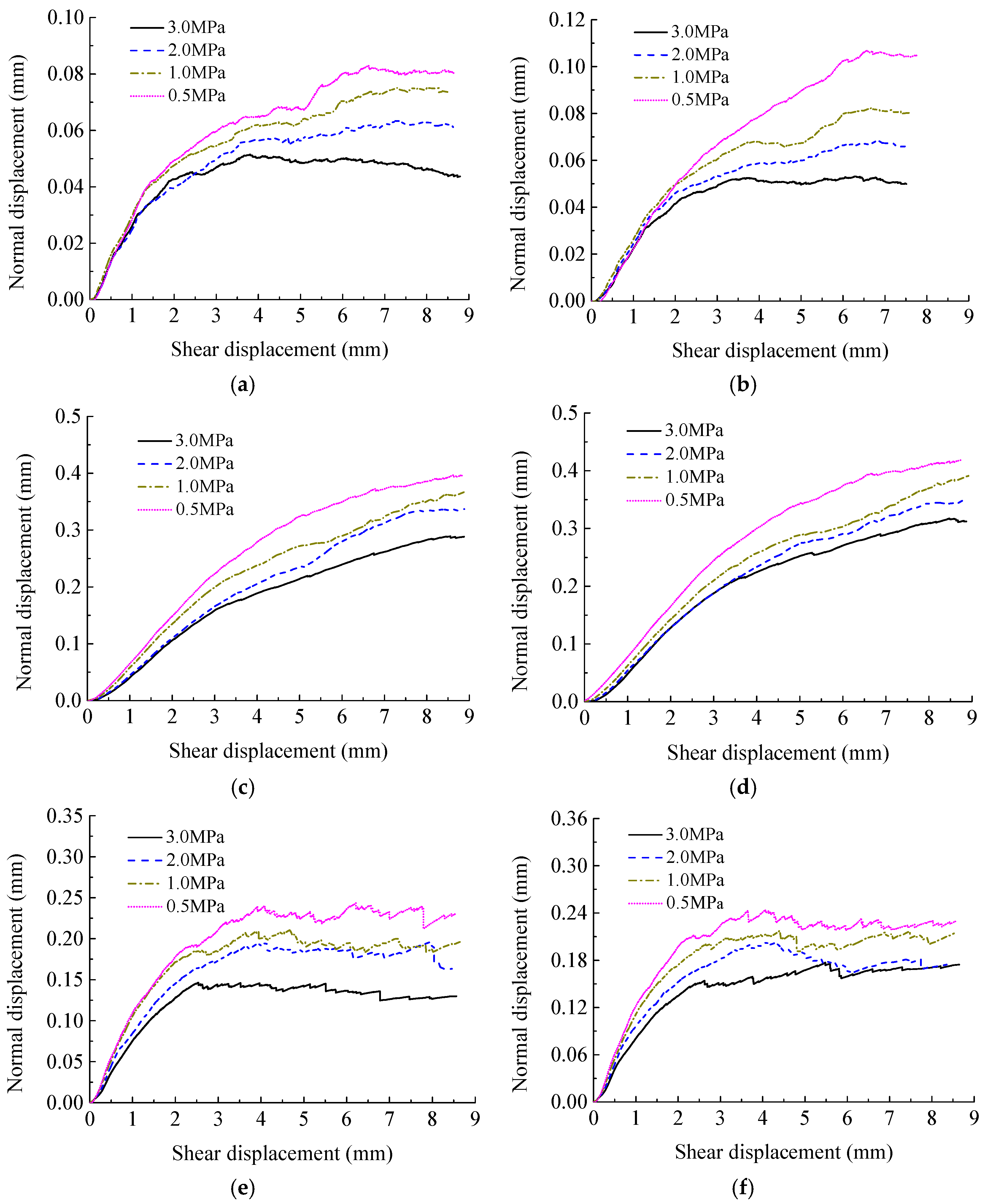
6.2. Dilation Law of Discontinuities Possessing Different Joint Wall Strengths
6.3. Shear and Dilation Properties of Rock–Mortar Discontinuities and Rock–Rock Discontinuities
7. Conclusions
- (1)
- Three-dimensional engraving technology can effectively fabricate joint specimens that are applicable to laboratory tests. The joint specimen fabricated by this method has the morphological characteristics of being highly consistent with the prototype, which is available to analyze the shear properties and morphological characteristics of the rock joint with different joint wall strengths made by various rock and rock-like materials.
- (2)
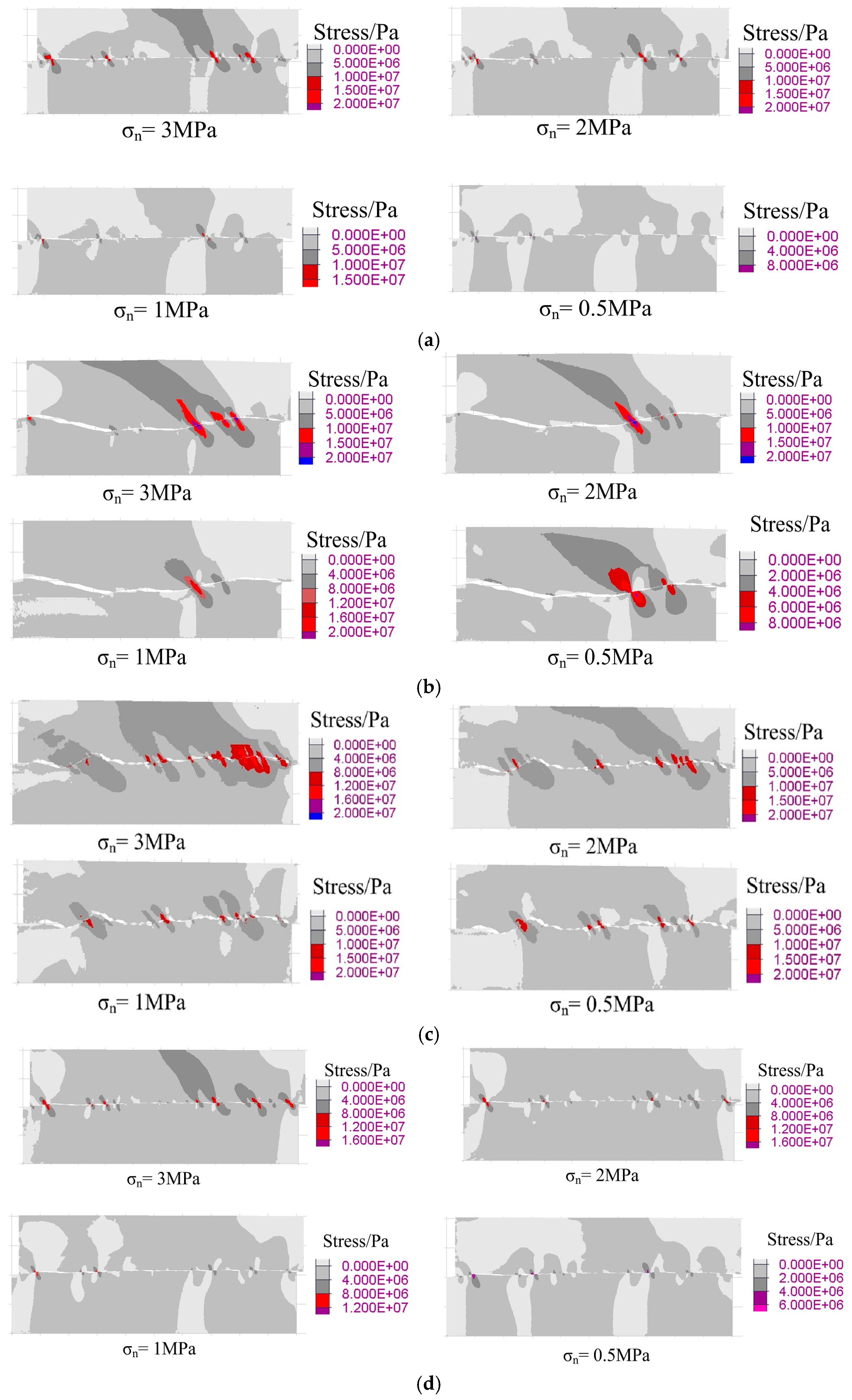
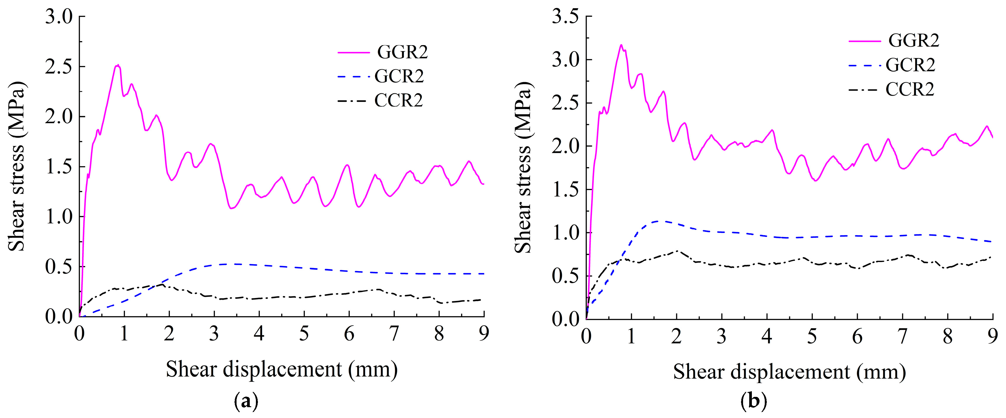
- The shear curve of the numerical simulation is basically consistent with the test curve, which verifies the accuracy of the CY constitutive model in simulating progressive failure of discontinuities possessing different joint wall strengths. Integrating the shear stress contour of the numerical simulation and the test results to analyze, the damage area in the shearing process of discontinuities possessing different joint wall strengths is mainly concentrated on the asperity facing the shear direction. The shear wear and cutting destruction of discontinuities possessing different joint wall strengths are mainly distributed in the soft rock.
- (3)
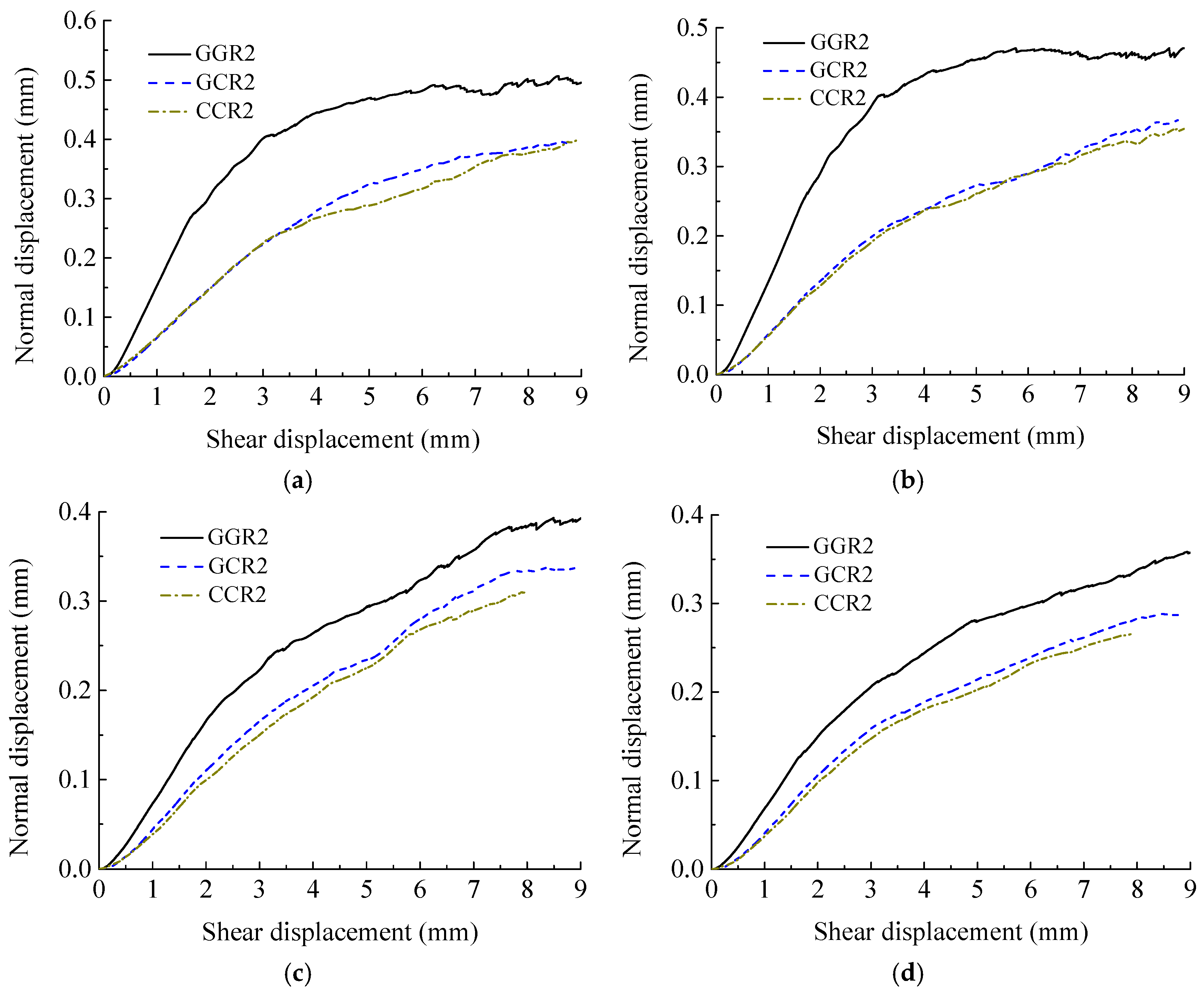
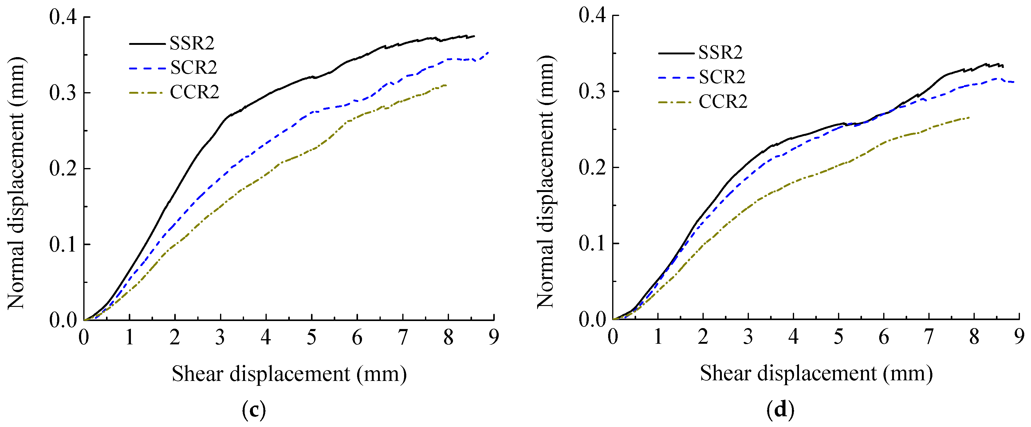
- The dilation displacement of discontinuities possessing different joint wall compressive strengths decreases with the increase in normal stress. Due to the cooperative effect of roughness and undulation, the dilation displacement of discontinuities possessing different joint wall strengths with JRC of 10.8 is the largest, discontinuities possessing different joint wall strengths with JRC of 18.7 is second and discontinuities possessing different joint wall strengths with JRC of 2.8 is the smallest. The embedding effect of asperities is enhanced and the climbing dilation effect is weakened as a result of the great difference in joint wall strength on both sides of granite–mortar discontinuities. Therefore, the dilation displacement of granite–mortar discontinuities is smaller compared with sandstone–mortar discontinuities.
- (4)
- On basis of the numerical results, the peak shear strength and residual shear strength of discontinuities possessing different joint wall strengths are between those of discontinuities possessing identical joint wall strengths composed of hard rock and discontinuities possessing identical joint wall strengths composed of soft rock. Meanwhile, the dilation displacement of discontinuities possessing different joint wall strengths is also between discontinuities possessing identical joint wall strengths composed of hard rock and discontinuities possessing identical joint wall strengths composed of soft rock.
Author Contributions
Funding
Institutional Review Board Statement
Informed Consent Statement
Data Availability Statement
Conflicts of Interest
References
- Liu, G.; Yang, Y. Deep Soft Rock Tunnel Perimeter Rock Control Technology and Research. Appl. Sci. 2025, 15, 278. [Google Scholar] [CrossRef]
- Liu, D.; Yan, W.; Yan, S.; Kang, Q. Study on the effect of axial and hydraulic pressure coupling on the creep behaviors of sandstone under multi-loading. Bull. Eng. Geol. Environ. 2021, 80, 6107–6120. [Google Scholar] [CrossRef]
- Dang, W.; Tao, K.; Fu, J.; Wu, B. Experimental investigation on unloading-induced sliding behavior of dry sands subjected to constant shear force. Appl. Sci. 2025, 15, 401. [Google Scholar] [CrossRef]
- Xie, S.; Jiang, Z.; Lin, H.; Ma, T.; Peng, K.; Liu, H.; Liu, B. A new integrated intelligent computing paradigm for predicting joints shear strength. Geosci. Front. 2024, 15, 40111884. [Google Scholar] [CrossRef]
- Zhang, X.; Cao, Z.; Yao, C.; Yang, J.; Ma, Y.; Ye, Z.; Zhou, C. Effect of nonstationarity on shear properties of rock joints and a new peak shear strength criterion. Int. J. Geomech. 2023, 23, 04023213. [Google Scholar] [CrossRef]
- Tang, Z.C.; Zhang, Z.F.; Zuo, C.Q.; Jiao, Y.Y. Peak shear strength criterion for mismatched rock joints: Revisiting JRC-JMC criterion. Int. J. Rock Mech. Min. 2021, 147, 104894. [Google Scholar] [CrossRef]
- Jiang, F.; Wang, G.; He, P.; Hou, B.; Zhang, S.B.; Sun, S.Q.; Zheng, C.C.; Wu, Y. Mechanical failure analysis during direct shear of double-joint rock mass. Bull. Eng. Geol. Environ. 2022, 81, 410. [Google Scholar] [CrossRef]
- Pirzada, M.A.; Bahaaddini, M.; Moradian, O.; Roshan, H. Evolution of contact area and aperture during the shearing process of natural rock fractures. Eng. Geol. 2021, 291, 106236. [Google Scholar] [CrossRef]
- Zhang, X.B.; Yi, L.; Yao, C.; Ma, Y.L.; Yang, J.H.; Jiang, Q.H.; Zhou, C.B. Comparative study on shear mechanical properties and failure mechanisms of rough joints under CNL and DNL boundary conditions. Chin. J. Rock Mech. Eng. 2025, 44, 865–880. (In Chinese) [Google Scholar]
- Pratomo, F.Y.; Wei, X.; Zou, C.; Zhao, G.F. Investigation of the shear failure of rock joints using the four-dimensional lattice spring model. Int. J. Rock Mech. Min. 2022, 152, 105070. [Google Scholar] [CrossRef]
- Barton, N.; Choubey, V. The shear strength of rock joints in theory and practice. Rock Mech. Rock Eng. 1977, 10, 1–54. [Google Scholar] [CrossRef]
- Grasselli, G.; Egger, P. Constitutive law for the shear strength of rock joints based on three-dimensional surface parameters. Int. J. Rock Mech. Min. 2003, 40, 25–40. [Google Scholar] [CrossRef]
- Moradian, Z.A.; Ballivy, G.; Rivard, P.; Gravel, C.; Rousseau, B. Evaluating damage during shear tests of rock joints using acoustic emissions. Int. J. Rock Mech. Min. 2010, 47, 590–598. [Google Scholar] [CrossRef]
- Asadi, M.S.; Rasouli, V.; Barla, G. A laboratory shear cell used for simulation of shear strength and asperity degradation of rough rock fractures. Rock Mech. Rock Eng. 2013, 46, 683–699. [Google Scholar] [CrossRef]
- Oliveira, D.; Indraratna, B. Comparison between models of rock discontinuity strength and deformation. J. Geotech. Geoenviron. 2010, 136, 864–874. [Google Scholar] [CrossRef]
- Hossaini, K.A.; Babanouri, N.; Nasab, S.K. The influence of asperity deformability on the mechanical behavior of rock joints. Int. J. Rock Mech. Min. 2014, 70, 154–161. [Google Scholar] [CrossRef]
- Atapour, H.; Moosavi, M. The influence of shearing velocity on shear behavior of artificial joints. Rock Mech. Rock Eng. 2014, 47, 1745–1761. [Google Scholar] [CrossRef]
- Rullière, A.; Rivard, P.; Peyras, L.; Breul, P. Influence of roughness on the apparent cohesion of rock joints at low normal stresses. J. Geotech. Geoenviron. 2020, 146, 04020003.1–04020003.15. [Google Scholar] [CrossRef]
- Rullière, A.; Rivard, P.; Peyras, L.; Breul, P. Influence of material strength on the apparent cohesion of unbounded gravity dam joints under low normal stress. J. Geotech. Geoenviron. 2021, 147, 06021012.1–06021012.8. [Google Scholar] [CrossRef]
- Tang, Z.C.; Wong, L.N.Y. New criterion for evaluating the peak shear strength of rock joints under different contact states. Rock Mech. Rock Eng. 2016, 49, 1191–1199. [Google Scholar] [CrossRef]
- Zhang, X.; Jiang, Q.; Chen, N.; Wei, W.; Feng, X. Laboratory investigation on shear behavior of rock joints and a new peak shear strength criterion. Rock Mech. Rock Eng. 2016, 49, 3495–3512. [Google Scholar] [CrossRef]
- Ban, L.; Qi, C.; Chen, H.; Yan, F.; Ji, C. A new criterion for peak shear strength of rock joints with a 3D roughness parameter. Rock Mech. Rock Eng. 2023, 53, 1755–1775. [Google Scholar] [CrossRef]
- Yang, J.; Xia, Y.; Chen, W.; Zhang, L.; Li, L. Shear behavior of silty clay–concrete interface based on large-scale direct shear test. Int. J. Geomech. 2023, 23, 04023084. [Google Scholar] [CrossRef]
- Lin, H.; Wang, M.; Xu, W.Z. Shear behaviors of the binary structural plane. Geotech. Geol. Eng. 2018, 36, 939–948. [Google Scholar] [CrossRef]
- Jiang, Y.; Wang, Y.; Yan, P.; Luan, H.; Chen, Y. Experimental investigation on the shear properties of heterogeneous discontinuities. Geotech. Geol. Eng. 2019, 37, 4959–4968. [Google Scholar] [CrossRef]
- Lin, H.; Han, L.; Wang, Y.; Cao, R.; Zhao, Y.; Jiang, C. Influence of the micro-deformation characteristics of binary media on the shear behavior of structural plane. Geotech. Geol. Eng. 2020, 39, 347–358. [Google Scholar] [CrossRef]
- Wu, Q.; Jiang, Y.; Tang, H.; Luo, H.; Wang, X.; Kang, J.; Zhang, S.; Yi, X.; Fan, L. Experimental and numerical studies on the evolution of shear behaviour and damage of natural discontinuities at the interface between different rock types. Rock Mech. Rock Eng. 2020, 53, 3721–3744. [Google Scholar] [CrossRef]
- Ghazvinian, A.H.; Taghichian, A.; Hashemi, M.; Mar’Ashi, S.A. The shear behavior of bedding planes of weakness between two different rock types with high strength difference. Rock Mech. Rock Eng. 2010, 43, 69–87. [Google Scholar] [CrossRef]
- Wu, Q.; Xu, Y.; Tang, H.; Fang, K.; Jiang, Y.; Liu, C.; Wang, X. Peak shear strength prediction for discontinuities between two different rock types using neural network approach. Bull. Eng. Geol. Environ. 2019, 78, 2315–2329. [Google Scholar] [CrossRef]
- Tang, Z.C.; Zhang, Z.F.; Jiao, Y.Y. Three-dimensional criterion for predicting peak shear strength of matched discontinuities with different joint wall strengths. Rock Mech. Rock Eng. 2021, 54, 3291–3307. [Google Scholar] [CrossRef]
- Zhang, X.; Zhu, X.; Yao, C.; Ouyang, S.; Yang, J.; Jiang, Q. Investigation on the shear behavior of rough rock joints prepared by three- dimensional engraving technique. J. Test. Eval. 2022, 50, 1425–1440. [Google Scholar] [CrossRef]
- Jiang, Q.; Feng, X.; Gong, Y.; Song, L.; Ran, S.; Cui, J. Reverse modelling of natural rock joints using 3D scanning and 3D printing. Comput. Geotech. 2016, 73, 210–220. [Google Scholar] [CrossRef]
- Jaber, J.; Conin, M.; Deck, O.; Moumni, M.; Godard, O.; Kenzari, S. Investigation of the mechanical behavior of 3D printed polyamide-12 joints for reduced scale models of rock mass. Rock Mech. Rock Eng. 2020, 53, 2687–2705. [Google Scholar] [CrossRef]
- Li, Y.; Zhang, Y. Quantitative estimation of joint roughness coefficient using statistical parameters. Int. J. Rock Mech. Min. 2015, 77, 27–35. [Google Scholar] [CrossRef]


| Property | Cement Mortar | Sandstone | Granite |
|---|---|---|---|
| Density ρ (g/cm3) | 2.10 | 2.43 | 2.80 |
| Uniaxial compression strength UCS (MPa) | 32.60 | 95.56 | 261.55 |
| Tensile strength σt (MPa) | 1.80 | 2.13 | 6.48 |
| Cohesion c (MPa) | 7.00 | 12.00 | 23.00 |
| Basic friction angle Φb (°) | 31.50 | 29.50 | 35.00 |
| Young’s module E (GPa) | 22.32 | 18.84 | 57.91 |
| Poisson’s ratio ν | 0.30 | 0.28 | 0.22 |
| Numerical Parameters | R | Øim (°) | Ø (°) | ||||
|---|---|---|---|---|---|---|---|
| SCR1 | 0.815 | 0.738 | 0.574 | 0.832 | 0.0008 | 32.530 | 30.270 |
| SCR2 | 0.932 | 0.796 | 0.865 | 0.894 | 0.0023 | 45.280 | 30.270 |
| SCR3 | 1.348 | 0.951 | 1.097 | 0.875 | 0.0047 | 46.840 | 30.270 |
| GCR1 | 0.946 | 0.803 | 0.681 | 1.073 | 0.0008 | 33.190 | 33.490 |
| GCR2 | 1.245 | 0.992 | 1.157 | 0.926 | 0.0023 | 43.450 | 33.490 |
| GCR3 | 1.578 | 1.179 | 1.437 | 0.841 | 0.0047 | 44.620 | 33.490 |
| σn (MPa) | SCR1 | SCR2 | SCR3 | GCR1 | GCR2 | GCR3 |
|---|---|---|---|---|---|---|
| 0.5 | 0.107 | 0.419 | 0.244 | 0.083 | 0.397 | 0.243 |
| 1 | 0.082 | 0.391 | 0.217 | 0.060 | 0.367 | 0.211 |
| 2 | 0.068 | 0.353 | 0.204 | 0.056 | 0.338 | 0.196 |
| 3 | 0.053 | 0.317 | 0.177 | 0.051 | 0.289 | 0.147 |
| Normal Stress (MPa) | The Identifier of Specimens | ||||
|---|---|---|---|---|---|
| SSR2 | SCR2 | CCR2 | GCR2 | GGR2 | |
| 0.5 | 0.468 | 0.419 | 0.398 | 0.397 | 0.506 |
| 1 | 0.418 | 0.391 | 0.355 | 0.367 | 0.471 |
| 2 | 0.376 | 0.353 | 0.311 | 0.338 | 0.398 |
| 3 | 0.337 | 0.317 | 0.265 | 0.289 | 0.362 |
Disclaimer/Publisher’s Note: The statements, opinions and data contained in all publications are solely those of the individual author(s) and contributor(s) and not of MDPI and/or the editor(s). MDPI and/or the editor(s) disclaim responsibility for any injury to people or property resulting from any ideas, methods, instructions or products referred to in the content. |
© 2025 by the authors. Licensee MDPI, Basel, Switzerland. This article is an open access article distributed under the terms and conditions of the Creative Commons Attribution (CC BY) license (https://creativecommons.org/licenses/by/4.0/).
Share and Cite
Zhang, X.; Ouyang, S.; Fan, C.; Yi, L.; Liu, D. Shear Properties and Failure Mechanism of Matched Discontinuities Between Two Different Rock Types Under Direct Shear. Appl. Sci. 2025, 15, 5289. https://doi.org/10.3390/app15105289
Zhang X, Ouyang S, Fan C, Yi L, Liu D. Shear Properties and Failure Mechanism of Matched Discontinuities Between Two Different Rock Types Under Direct Shear. Applied Sciences. 2025; 15(10):5289. https://doi.org/10.3390/app15105289
Chicago/Turabian StyleZhang, Xiaobo, Shu Ouyang, Chenglong Fan, Le Yi, and Da Liu. 2025. "Shear Properties and Failure Mechanism of Matched Discontinuities Between Two Different Rock Types Under Direct Shear" Applied Sciences 15, no. 10: 5289. https://doi.org/10.3390/app15105289
APA StyleZhang, X., Ouyang, S., Fan, C., Yi, L., & Liu, D. (2025). Shear Properties and Failure Mechanism of Matched Discontinuities Between Two Different Rock Types Under Direct Shear. Applied Sciences, 15(10), 5289. https://doi.org/10.3390/app15105289