Article

Research on the Mechanical Properties of Fiber-Reinforced Bamboo Board and Numerical Simulation Analysis of the Structural Mechanical Properties of Products

by
Huilong Wang
and
Baoshi Jiang
*
School of Civil Engineering and Architecture, Hainan University, Haikou 570228, China
*
Author to whom correspondence should be addressed.
Appl. Sci. 2025, 15(10), 5288; https://doi.org/10.3390/app15105288
Submission received: 8 April 2025 / Revised: 2 May 2025 / Accepted: 7 May 2025 / Published: 9 May 2025
(This article belongs to the Section Civil Engineering)

Abstract

:
Bamboo is a fast-growing biomass material with excellent performance, making it a preferred choice for the development of green and low-carbon building materials. However, challenges such as combustibility and difficulties in processing and utilization persist. In this study, bamboo chips are wrapped in fiberglass cloth and cemented with magnesium oxychloride cement (MOC) to develop green, environmentally friendly, flame-retardant, and carbon-storing bamboo-based composite panels. Firstly, the optimal ratio of the inorganic adhesive MOC was systematically investigated, and flue gas desulfurization gypsum (FG) was added to enhance its water resistance. The flexural strengths of the composite board in the direction of the bamboo fiber and that perpendicular to it were found to be 15.71 MPa and 34.64 MPa, respectively. Secondly, numerical simulations were conducted alongside plate experiments, analyzing the floor and wall made from the boards. The results indicate that since the fiber-reinforced bamboo board as a lightweight wall can meet the requirements for a two-story building, it does not satisfy safety standards as a floor slab due to the higher loads. Despite this limitation, the fiber-reinforced bamboo board shows promising application prospects as a green and low-carbon alternative.

1. Introduction

In the context of “carbon peak, carbon neutral” [1], the development of low-carbon and environmentally friendly [2] building materials is of great significance. Wood is a low-carbon and green material. Currently, many scholars have conducted relevant research on wood boards. Wang [3] conducted research on fiber-reinforced wood board. The research shows that fiber-reinforced wood board falls within the category of biomass composite materials, which are non-toxic, harmless, and recyclable materials. This new type of building material is applied to the construction of low-rise rural buildings and shows excellent seismic performance. Zhang [4] conducted research on fiber-reinforced wood board and set up 10 specimens of fiber-reinforced wood board. The test results show that the seismic bearing capacity of the three-layer fiber-reinforced wood board structure meets the requirements of national code standards. Pi [5] conducted research on fiber-reinforced wood board, mainly focusing on conducting bending tests on five fiber-reinforced wood board beams. It was verified that the structure has a high safety reserve. It was suggested that the design of low-rise residences adopt the allowable stress method. Kymalainen [6] conducted a study on the surface corrosiveness of wood. Musselman [7] conducted a study on fiberboard wood frame shear walls with or without openings under circular loads.
To cope with global climate change and promote sustainable economic development, it is a good scheme that fast-growing bamboo is taken as a substitute for wood to produce building materials. In order to prevent the shortage of wood [8], improve the utilization rate of bamboo materials [9,10,11], and solve problems such as the disposal of waste materials after bamboo processing, it has played a certain promoting role in the research and development of bamboo board [12].
This paper proposes a new type of fiber-reinforced bamboo board. The inorganic binder is very crucial. The material magnesium oxychloride cement (MOC) [13,14,15], which is considered a high-quality inorganic binder, has been extensively studied. MOC is used as the binder, bamboo is used as the basic material, and glass fiber cloth is used to wrap bamboo materials as reinforcing materials. Through reasonable material design and preparation processes and combining the advantages of bamboo and MOC organically, the aim is to develop a high-performance and sustainable building material [16,17]. It is expected to demonstrate good application potential in the field of low-rise buildings, especially suitable for floor slabs and wall structures. Using the verified modeling method, the three-dimensional finite element models of typical wall panel elements and floor slab components were constructed, respectively. Through numerical simulation of the load action under different working conditions, the anti-lateral displacement performance of the wall structure, the vertical stiffness and deflection of the floor slab, and other mechanical properties were systematically analyzed, providing a theoretical basis for subsequent engineering applications.

2. Test of Binder Ratio and Mechanical Properties of Fiber-Reinforced Bamboo Substrate

2.1. Test Materials

An industrial-grade light-burned magnesium oxide powder (MgO) with an experimental activity of 65% was used in this study. This test material was a white powder sourced from Shandong Jiuzhong Chemical Co., Ltd. (Weifang, China). The selected MgO meets the “light-burned magnesium oxide for magnesite products” standard (WB/T 1019-2002) [18].
The second material was an industrial-grade magnesium chloride hexahydrate (MgCl2·6H2O), a translucent crystalline solid made in Golmud, China.
The other test materials included an inert filler flue gas desulfurization gypsum (FG), produced by Shandong Jiuzhong Chemical Co., Ltd.; an additive (a water-resistant modifier); water (laboratory tap water); and a fiberglass fabric from Qing Xi Hongxin Building Materials Management Department (Cangzhou, China).

2.2. Optimum Ratio of MOC Mortar

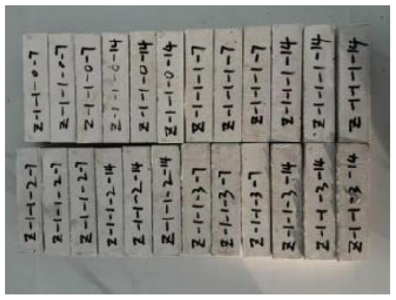
2.2.1. Ratio of MOC Specimen

When MOC is selected as the cementing agent for bamboo substrate, several factors affecting its mechanical properties must be considered [19], including the optimal ratio, which is the primary factor. Variations in the optimal ratio of MOC usually result in differences in the final hydration products, which in turn affect the mechanical properties of MOC. The hydration products include 3Mg(OH)2·MgCl2·8H2O (3·1·8 phase) and 5Mg(OH)2·MgCl2·8H2O (5·1·8 phase) [20]. Therefore, determining the ratio of MOC mortar is essential.
Since gypsum can enhance the mechanical properties of MOC and improve its water resistance, an optimal ratio was established by testing the mechanical properties of MOC specimens prepared with different ratios and varying gypsum amounts, as shown in Table 1. The selected MOC ratio served as the cementing agent for the fiber-reinforced bamboo board, offering superior bonding strength and improved water resistance for the board.

2.2.2. MOC Specimen Production

To prepare MOC samples, industrial magnesium chloride, water, and the water-resistant modifier were first weighed according to the mass ratio of 1:1:0.04. Industrial magnesium chloride and water were then added to a stirring pot to create a magnesium chloride solution, followed by the addition of the weighed water-resistant modifier, which was stirred into the mixture. The mixture was stirred for 5 min at a speed of 120 r/min. The mixer complies with the “Mixer for mixing mortars” (JC/T 681) standard [21]. Lightly burned magnesia powder was then incorporated into the solution, with the MgO powder and gypsum prepared according to the mass ratio in Table 1. These were then poured into the blender in sequence. The mixture [22] was stirred for 5 min at a speed of 120 r/min and then injected into a standard triple test mold measuring 40 mm × 40 mm × 160 mm after mixing thoroughly [23]. The fresh sample was covered with a plastic sheet to prevent evaporation, and the MOC sample was demolded after initial curing at room temperature for 24 h, as shown in Figure 1. The demolded MOC specimen was placed in a curing chamber at a temperature of 20 ± 3 °C and 65% relative humidity for further solidification. The MOC specimens were cured for 7 days, 14 days, and 28 days, respectively, after which their performance was tested.

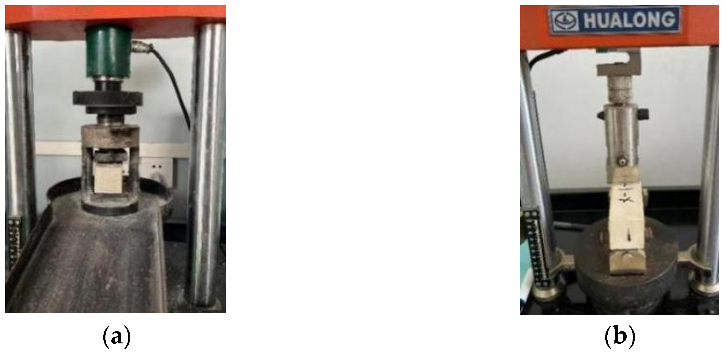
2.2.3. Mechanical Property Test of MOC Specimen

The flexural and compressive strengths of the MOC specimens were tested in accordance with the “Test Method for the Strength of Cement Mortar” (GB/T 17671-2021) [24]. The testing was conducted using WHY-5 and WHY-200 microcomputer-controlled automatic pressure testing machines [25]. The samples were placed in the curing room and cured for 7 days, 14 days, and 28 days, respectively. When the flexural strength was tested, there were 3 samples in each group, as shown in Figure 2a, and the results were averaged. After testing the flexural strength, the broken samples were taken for compressive strength testing, as shown in Figure 2b, with six samples in each group, and the average values were recorded.
Initially, the bending strength test was conducted by placing the specimen on the test machine, setting the load rate at 2.4 kN/s, and continuously applying the load until the specimen failed [26]. The load value at the time of failure was recorded. Subsequently, the broken-in-half prism was placed on the test machine again, and the load was continued at the same rate until it was destroyed [27].

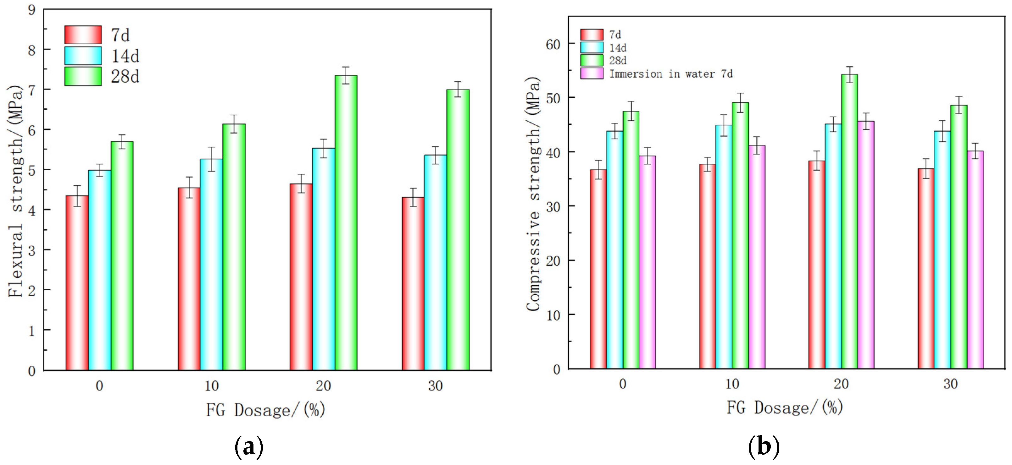
2.2.4. Analysis of Experimental Results of MOC Material Properties

Different amounts of flue gas desulfurization gypsum (FG) were added to assess their impact on the mechanical properties of the MOC specimens. The test results in Figure 3a,b indicate that the flexural strength and compressive strength of MOC specimens initially increased and then decreased with the increasing FG content, as shown in Table 2. When the ratio was n (MgO):n (MgCl2·6H2O):n (water-resistant modifier):n (H2O):n (gypsum) = 2:1:0.08:1:0.4, the bending strength and compressive strength of the specimen cured for 28 days under this ratio were 7.35 MPa and 54.25 MPa, respectively. The flexural strength and compressive strength increased by 28.9% and 12.8%, respectively, compared with the control group without FG addition. Therefore, the mechanical properties of MOC were optimized when FG content reached 20%.
As shown in Figure 3 and Table 2, when FG content reached 20%, the compressive strength of the specimens immersed in water for 7 days was 44.25 MPa. Compared with the specimens that were not immersed in water, the compressive strength decreased by only 15.83%. It shows that MOC has better mechanical properties and a denser internal structure under this ratio, which reflects that water does not easily penetrate the interior of MOC and the MOC under this ratio has the best water resistance.
These results suggest that being an inert filler, FG can promote the hydration reaction of MOC, adjust its colloidal properties, and thus enhance its strength and hardness. When FG content reaches 30%, excessive FG can reduce the content of reaction products in MOC, leading to residual FG and decreased sample strength. Furthermore, FG particles can aggregate and hinder significant strength reduction.
According to the results of the experimental analysis, the binder with the optimal ratio can be selected. It provides convenience for the subsequent production of fiber-reinforced bamboo board, reflecting the necessity and relevance of this research.

2.3. Fabrication and Performance Test Analysis of Fiber-Reinforced Bamboo Substrate

2.3.1. Fabrication of Fiber-Reinforced Bamboo Board

The fiber-reinforced bamboo board is constructed using high-quality original bamboo as the primary material, the optimal FG-modified MOC as the cementing agent, and glass fiber cloth as the reinforcing material. The binder material for the fiber-reinforced bamboo substrate in this study contained n (MgO):n (MgCl2·6H2O):n (water-resistant modifier):n (H2O):n (gypsum) in the ratio 2:1:0.4 MOC. To comply with the national standard “Building Decoration Materials Glass Fiber Mesh Cloth” (GB/T 8696-2008) [28], a glass fiber cloth with a density of 12 × 12/cm2 was used. The glass fiber cloth was cut to a size of 600 mm × 240 mm × 0.16 mm and used to wrap the bamboo strips. The glass fiber cloth was used as the reinforcement material to create three specimens, and the final average values were recorded. The plate was fabricated in accordance with the “Boaeds of magnesium oxychloride cement” (JC/T568-2007) [29] with dimensions of 250 mm × 250 mm × 12 mm, as shown in Figure 4d. A mold was used to create the fiber-reinforced bamboo board, and its performance was then tested.
The fabrication process of the fiber-reinforced bamboo board is illustrated in Figure 4. Initially, bamboo slices were cut to dimensions of 240 mm × 30 mm × 5 mm, with eight bamboo slices placed on the glass fiber cloth, leaving a 1 mm gap between the slices, as shown in Figure 4a, and a 1.5 mm gap between the outermost slices and the mold edge to facilitate MOC cementation. The bamboo slices were wrapped in glass fiber cloth, as shown in Figure 4b. Approximately 5 mm thick MOC slurry was poured into the mold and smoothed. The wrapped bamboo pieces were then pressed into the slurry, adjusted for position, and the test mold was filled with the prepared MOC slurry. Finally, bubbles were removed with a gray knife, and the surface was scraped flat. The size of the sample was 250 mm × 250 mm × 12 mm, as shown in Figure 4d. After standing for 24 h, demolding was performed. The obtained specimens are shown in Figure 4d. The specimens were cured in a curing room with an ambient temperature of 20 ± 5 °C and a relative humidity of ≥55% for 28 days.

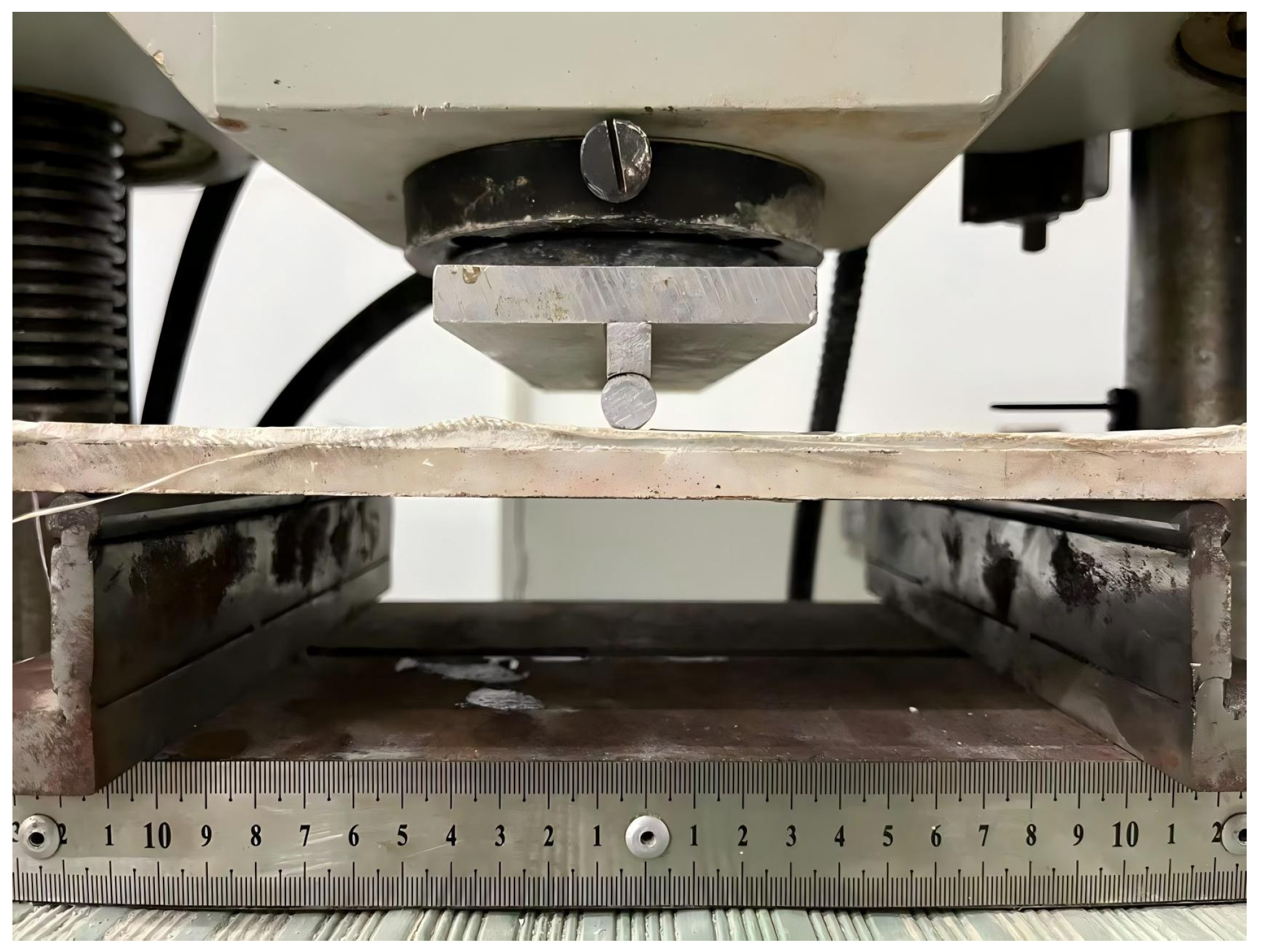
2.3.2. Performance Test and Results of Fiber-Reinforced Bamboo Substrate

Flexural strength was tested in accordance with the “Test Method for Fiber Cement Products” (GB/T 7019-2014) [30]. A universal testing machine was used to conduct two flexural strength tests on each specimen [31], as shown in Figure 5. The second flexural strength test involved reassembling the damaged specimens according to the fracture section after the first test and loading them in a direction perpendicular to the loading direction of the first test. Due to the single-layer bamboo board, the bending resistance of the plate varies with the direction of the bamboo fiber, leading to significant differences in the test results. The strength of the vertical bamboo fiber section is higher, while the strength of the horizontal bamboo fiber section is lower. Consequently, the data results of a sheet were averaged based on the low and high values from the two tests [32] to obtain the bending strength of the longitudinal and vertical bamboo fiber cross-sections.
The flexural strength test of the fiber-reinforced bamboo board shows that the average bending strengths of the plate segments in the direction of bamboo fibers and perpendicular to the direction of bamboo fibers are 15.71 MPa and 34.64 MPa, respectively. The changes during the loading process of the specimens demonstrate that the glass fiber cloth has excellent strength reserves. After the MOC bonding of the bamboo strips, the board maintains good flexural resistance.
During the bending property test of the section of the board in the direction of the bamboo fiber, the external tension side of the MOC first cracked with an increase in the applied load, followed by the MOC of the glass fiber cloth, and finally breaking at the MOC cement between the bamboo fibers. This demonstrates that the glass fiber and MOC are the primary load-bearing components when the section is stressed in the direction of the bamboo fiber, while the bamboo material contributes when the section is stressed perpendicular to the bamboo fiber. The mechanical properties of the plate thus exhibit anisotropy.
Through the experimental results, the fiber-reinforced bamboo board demonstrates excellent flexural resistance. The board meets the strength requirements of grade R3 as stipulated in “Fiber cement flat sheets—Part 1: Non-asbestos fiber cement flat sheets” (JC/T 412.1-2018) [33]; it provides conditions for analyzing the mechanical properties of walls and floor slabs made of this board.

3. Numerical Simulation of Fiber-Reinforced Bamboo Substrate and Comparison with Experimental Results

ABAQUS is a powerful and widely recognized finite element analysis software—particularly in the field of nonlinear analysis—that has been extensively utilized in various countries [34]. In this study, ABAQUS 2024 was employed to model the fiber-reinforced bamboo board and its components. The internal structure of this type of plate consists of three components—bamboo strips, glass fiber cloth, and MOC—all simulated using solid units and assigned corresponding material properties. The geometric modeling of bamboo strips involves selecting eight strips measuring 240 mm × 30 mm × 5 mm, arranged with a 1 mm gap in the middle, which is filled with MOC. The arranged bamboo strips are wrapped in glass fiber cloth with a thickness of 0.16 mm, and the wrapped model is filled with MOC around it to achieve the desired thickness. The dimensions of the fiber-reinforced bamboo board are shown in Figure 6a. The substrate is constrained at both ends, consistent with the test setup, and the load is applied in both the direction of the bamboo fiber and along the bamboo fiber direction, as shown in Figure 6b.
In this study, bamboo strips, glass fiber cloth, and MOC are treated as isotropic materials. Although bamboo is inherently anisotropic, the material properties in the direction of bamboo fiber were primarily used in this analysis. The elastic modulus in the direction of bamboo fiber length was selected for the simulation. The glass fiber cloth is a bidirectional orthogonal mesh cloth that primarily enhances the tensile properties of the vertical cross-section with bamboo fiber. The parameters required for the MOC and bamboo strips were obtained in accordance with the test results, with the constitutive curves illustrated in Figure 7. The parameters for the glass fiber cloth were determined based on factory test reports. The glass fiber is strong, and it did not break during testing, allowing it to be considered as linearly elastic. The elastic modulus of the glass fiber cloth was 100 GPa, Poisson’s ratio was 0.2, and the mass density was 200 kg/m3. The ultimate tensile strain (εtu), yield strain (εy), and ultimate compressive strain (εcu) were 0.083, 0.025, and 0.04, respectively. For MOC, the ultimate tensile strain (εtu), yield strain (εy), 0.44εcu, and ultimate compressive strain (εcu) were 0.007, 0.009, 0.027, and 0.061, respectively. The material parameters are summarized in Table 3.
For the numerical simulation of the flexural specimens, the geometric model and loading of the fiber-reinforced bamboo board were consistent with the test. In the first stage, the load was increased by 4 kN seven times, while in the second stage, it was increased by 1 kN five times.
The load–displacement curve in the vertical direction of the bamboo fiber was obtained through analysis, as shown in Figure 8a. When the linear load was applied in the direction of the bamboo fiber, an increase of 1 kN per stage was observed, and the load–displacement curve in the direction of the bamboo fiber was obtained after analysis, as shown in Figure 8b. The simulation results show that the yield loads of the plates perpendicular to and along the direction of the bamboo fiber were 25 kN/m and 10 kN/m, respectively. The maximum Mises stress in the direction of the vertical bamboo fiber reached 33.74 MPa, as shown in Figure 9, while the experimental strength was 34.64 MPa, resulting in an error of approximately 2.6%. The maximum Mises stress along the bamboo fiber was 14.52 MPa, compared to the experimental value of 15.71 MPa, with an error of about 7.6%.
These findings demonstrate that the numerical simulation modeling method employed in this study effectively simulated the properties of the sheet material. The accuracy of the flexural resistance performance test of fiber-reinforced bamboo board was verified. It provides conditions for the numerical simulation analysis of the mechanical properties of the walls and floor slabs fabricated from this board.

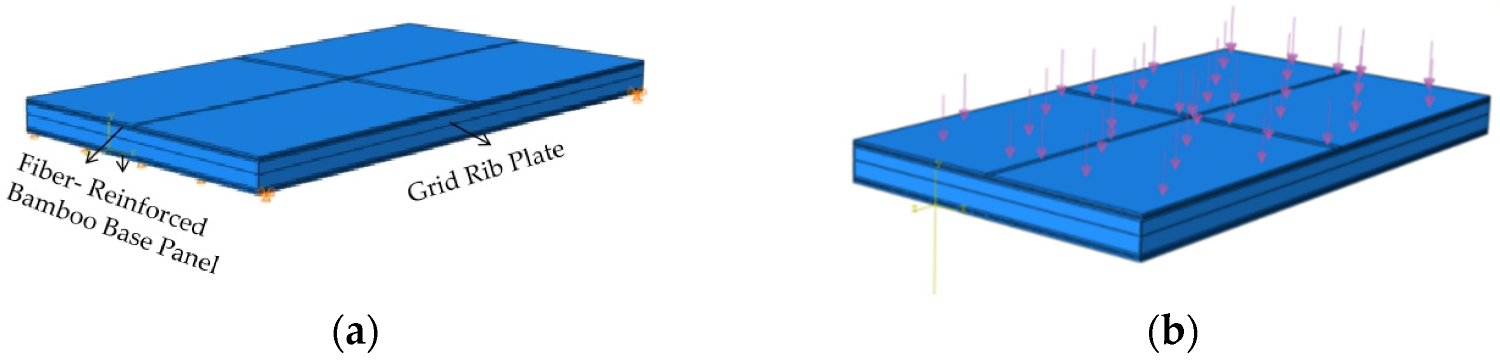
4. Numerical Simulation Analysis of Fiber-Reinforced Bamboo Floor

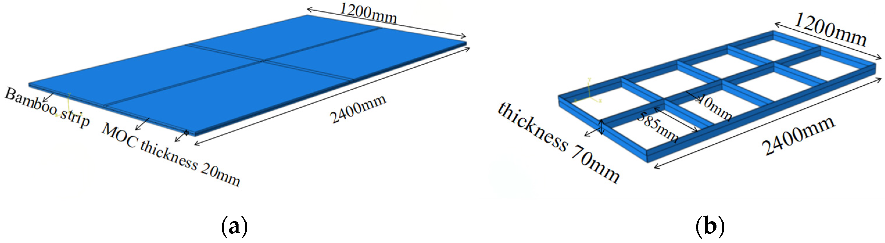
4.1. Numerical Modeling

The fiber-reinforced bamboo floor was designed based on the structure of fiber-reinforced wood-based floors. The floor consisted of fiber-reinforced bamboo board on both sides, with a bamboo grid rib in the middle, constructed using MOC-bonded cladding panels and rib. The fiber-reinforced bamboo board comprised 20 bamboo strips measuring 2350 mm × 55 mm × 10 mm, arranged successively with a 3 mm gap between the strips. MOC bonding was used to make a fiber-reinforced bamboo board panel measuring 2400 mm × 1200 mm × 20 mm by wrapping glass fiber cloth around the arranged bamboo board. The geometric modeling results are shown in Figure 10a. In addition to the upper and lower fiber-reinforced bamboo base plates, a grid rib plate was situated in the middle of the wall, measuring 2400 mm × 1200 mm × 70 mm, as depicted in Figure 10b.
The floor measured 2440 mm × 1220 mm × 120 mm, with a span length of 2.44 m, and a swept grid was employed for division. Uniformly distributed hinge supports were positioned at the bottom of both sides of the floor, as shown in Figure 11a. The dead weight of the floor was calculated as 4.58 kN/m2, with a sub-coefficient of 1.3. In accordance with the “Load code for the design of building structures” (GB50009-2012) [35], the live load for residential building floors was 2.0 kN/m2, with a sub-coefficient of 1.5. Consequently, a surface load of 4.374 kN/m2 was applied to the upper side of the floor (this value excluded the dead weight, which the software calculated at 1.0 times the dead weight based on material density), as shown in Figure 11b.

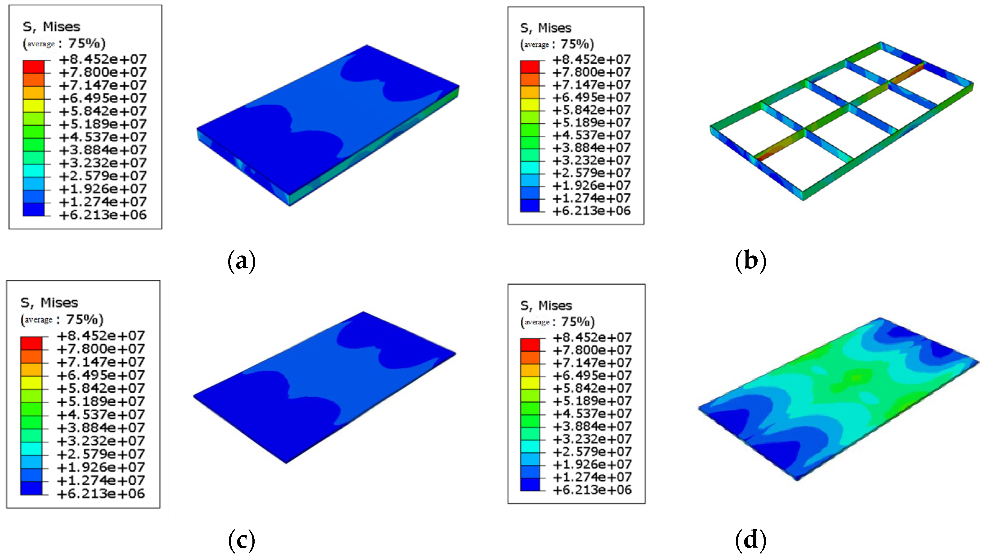
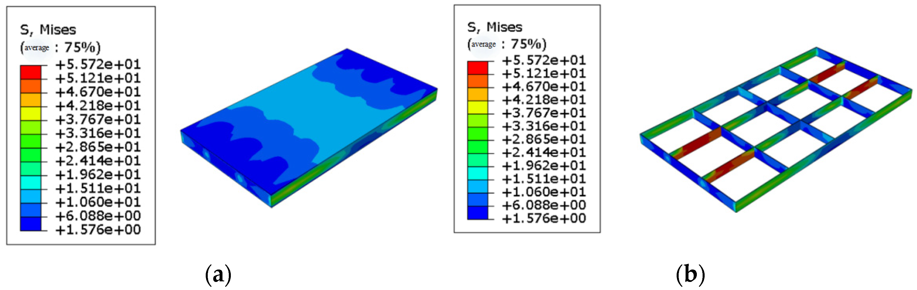
4.2. Result of Analysis

Through simulation, the stress distribution of the fiber-reinforced bamboo floor is illustrated in Figure 12a, while the stress distribution of the grid floor is shown in Figure 12b. The maximum Mises stress of the floor made from fiber-reinforced bamboo board reached 84.52 MPa, occurring in the span of the grid slab, indicating that it does not meet the corresponding requirements. The maximum compressive stress of the upper floor plate was 17.64 MPa, as shown in Figure 12c, which meets the compressive strength requirements of the material. The maximum axial tensile stress of the lower slab was 58 MPa, as shown in Figure 12d. Thus, the lower plate experienced uniform axial tension, which could be referenced against the tensile strength of the bamboo strip, recorded at 165.99 MPa, satisfying the tensile strength requirements.
The discrepancy in maximum stress between the upper and lower plates was because the floor plates transfer the uniform load from the upper plate to the lower plate through the grid; the upper plate receives uniform surface load, while the lower plate bears concentrated line load from the grid. The maximum deflection in the floor span reached 6.51 mm. In accordance with the “Code for design of concrete structures” (GB50010-2015) [36] on the floor-deflection requirements, the limit was 1/250 of the span L, which resulted in a deflection limit of 9.76 mm. The maximum deflection of the floor meets the design standard requirements. Therefore, the floor with a height of 120 mm and a span of 2.4 m did not meet the requirements for use.
To improve the aforementioned results, the grid slab in the fiber-reinforced bamboo floor was enhanced by adding one rib along the short side of the span direction, while the other remained unchanged. The upper and lower panels are consistent with those described in Section 4.1, which is numerically simulated. As shown in Figure 13, the maximum Mises stress of the floor made from fiber-reinforced bamboo substrate was 55.72 MPa, occurring on the grid floor, which was close to the compressive strength of the board and can be considered safe. The maximum deflection of the floor reached 5.94 mm, meeting the design standard requirements.
In summary, when using this material in the design of a light hollow floor, it is essential to properly reinforce the ribs to ensure safety and maintain material strength stability. This necessitates a high level of professional expertise among structural designers. The application of fiber-reinforced bamboo board in floor slabs in actual engineering scenarios is therefore discouraged.

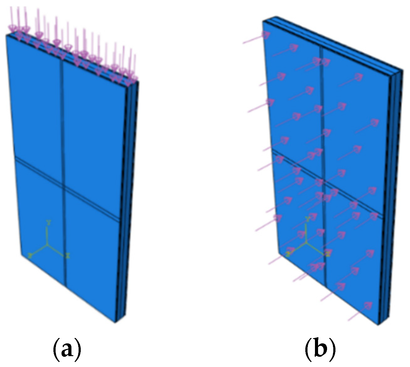
5. Numerical Simulation of Fiber-Reinforced Bamboo Wallboard

5.1. Numerical Modeling

The structure, size, material parameters, and mesh division of the wallboard made from fiber-reinforced bamboo substrate were consistent with those of the floor described in Section 4.1. All components were modeled using solid C3D8R hexahedral elements, as outlined in Section 3. A wall with dimensions of 2440 mm × 1220 mm × 120 mm can be constructed using the aforementioned parts, as shown in Figure 14a. A fixed constraint was applied to the bottom of the fabricated wall panel, with a horizontal lateral constraint applied to the top, as illustrated in Figure 14b.
To determine the vertical bearing capacity of the wall, a vertical uniform load transmitted from the upper layer was applied to the top of the wall. To assess the safety performance of the wall under wind pressure, a uniform horizontal load was applied to the side of the wall. The vertical uniform load on the top of the wall was calculated in accordance with the “Design Standard of Wood Structures” (GB 50005-2017) [37]. Since the wall panel was to serve as a load-bearing wall for a low-rise building, the building was assumed to be two stories high, with room dimensions of 4 m (length) × 4 m (width) × 3 m (height), resulting in a bearing area of 16 m2. The mass density is provided in Table 2, and the load component factor is 1.3, leading to a line load of 19.62 kN/m applied to the wall, as depicted in Figure 15a. The wind load was calculated in accordance with the “Load Code for Building Structures” (GB50009-2012). Assuming the wall to be an ordinary building, the wind pressure for Haikou once in 50 years was adopted, with a basic wind pressure of 0.7 kN/m2 and a sub-coefficient of 1.5. The gust coefficient was 1.7, as per the “Load Code for Building Structures” (GB50009-2012), resulting in a calculated wind load of 1.785 kN/m2. The loading model is shown in Figure 15b, and numerical simulation analysis of the mechanical properties was conducted.

5.2. Result of Analysis

The Mises stress was observed to increase from top to bottom, as shown in Figure 16a, and this increase is attributable to the self-weight of the wall: as the wall descends, self-gravity increases, resulting in greater compressive stress. The standard compressive strength of MOC obtained from testing was 54.25 MPa, while the calculated design compressive strength was 38.74 MPa. The maximum Mises stress (compressive stress) of the wall meets the design value of the MOC compressive strength obtained from testing, ensuring the safety of the wall. The ultimate displacement was recorded at 2.1 mm, as shown in Figure 16b. Given the wall height of 2440 mm, the displacement angle was about 1/1173, while the shear wall requirement was less than 1/600. Therefore, the wall panel meets the shear wall requirements. In design, the displacement must adhere to the normal use limit state.
When wind load is applied to the fiber-reinforced bamboo base wallboard, the maximum Mises stress reaches 7.216 MPa, as shown in Figure 17a. The test results indicate that the bending strength of the fiber-reinforced bamboo baseboard is 15.71 MPa. Therefore, under wind load, the maximum Mises stress of the wall panel does not reach the ultimate strength of the panel, indicating that the wall panel can function normally during gusty wind conditions. The maximum deflection of the wall panel under wind load is 1.024 mm, as shown in Figure 17b, which meets the displacement requirements for the use stage. Thus, the simulation results align with the relevant specifications for wall design.

5.3. Analysis of Lateral Force Resistance of Fiber-Reinforced Bamboo Wallboard

To investigate the lateral force resistance of the fiber-reinforced bamboo wallboard, ABAQUS was employed to simulate the wallboard under continuous loading. The dimensions of wall panels, the modeling parameters, and constraints applied are consistent with those described in Section 5.1. A continuously increasing concentrated load was applied to the side of the wall to simulate the lateral force resistance of the wall panels. The lateral load was gradually increased in two stages: the first stage involved an increase of 4 kN per stage for eight iterations, while the second stage involved an increase of 1 kN per stage for seven iterations. The load–displacement curve of the wall obtained through analysis is shown in Figure 18, revealing that the covered wall panel serves as the main lateral force-resistant component in the composite wall.
As the lateral horizontal load increases, the effectiveness of the panel gradually increases until the specimen reaches its ultimate bearing capacity. The results in this study indicate that with increasing load, displacement also increases, and that the relationship between load and displacement is linear at the initial stage. When the lateral concentrated force reached 29 kN, the structural stiffness decreased. Considering the material characteristics of the fiber-reinforced bamboo substrate, the yield displacement was defined as the maximum displacement at the end of the elastic stage, with a value of 0.6773 mm. It could thus be inferred that the ultimate lateral resistance of the fiber-reinforced bamboo wallboard was 29 kN, indicating the wall has significant lateral force resistance.

6. Conclusions

This paper presents a bio-based environmental protection board composed of bamboo as the main body, MOC as the adhesive, and glass fiber mesh cloth as reinforcement. The board binder is MOC, which was formulated by adding 20% FG, and the density of the glass fiber cloth is 12 × 12/cm2. Through the testing and simulation of the mechanical properties of the fiber-reinforced bamboo board, as well as numerical simulation analysis of walls and floors made of fiber-reinforced bamboo board, the following conclusions can be drawn:
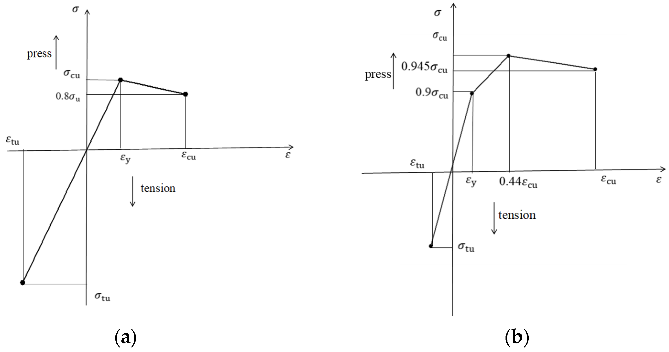
  • In the mechanical property test of MOC, the mechanical properties of MOC were optimized when FG content reached 20%. At this moment, the bending strength and compressive strength of the specimen cured for 28 days were 7.35 MPa and 54.25 MPa. This paper does not analyze the integration situation and physical properties of glass fibers but only studies the mechanical property tests of the composite. The experimental results show that the bending strengths of the plate section in the direction of and perpendicular to the bamboo fiber were 15.71 MPa and 34.64 MPa, respectively. The mechanical properties of the plate thus exhibit anisotropy.
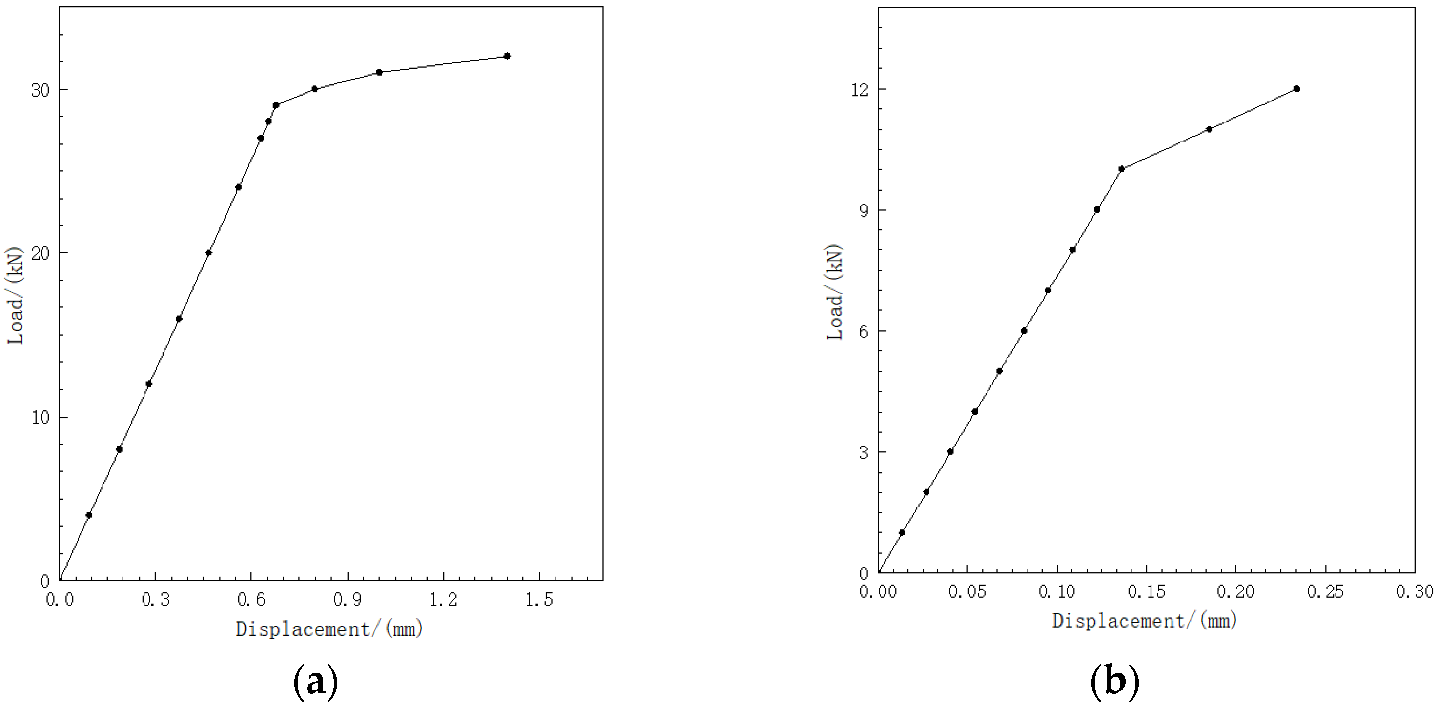
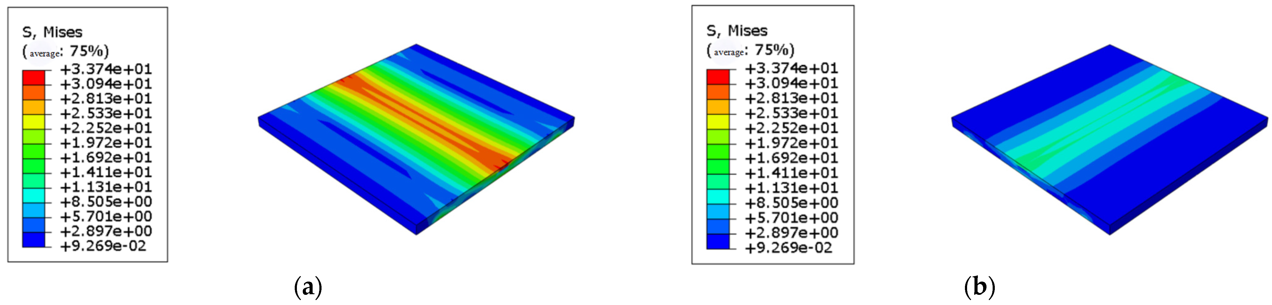
  • The numerical simulation of the board and the wall and floor modules indicates that when a 25 kN/m line load is applied in the vertical direction of the board bamboo fiber, the maximum Mises value is 33.74 MPa, with an error of approximately 2.6% compared to the test. When a 10 kN/m line load is applied to the board along the bamboo fiber direction, the maximum Mises value is 14.52 MPa, with an error of about 7.6% compared to the test. Additionally, the strain distribution of the components obtained by finite element simulation aligns well with that in the test.
  • The simulation of the fiber-reinforced bamboo floor slab shows that the maximum deflection in the span of the floor slab meets the requirements. However, the maximum Mises stress is located on the grid plates, which is the weak part of the structure, making it difficult to meet the corresponding strength requirements. Given that there are no relevant specifications for this type of structure as a reference, high professional quality is required of engineering designers. Therefore, it is not recommended to use it as a floor. If there are relevant requirements, structural design should be completed by a professional design team, along with material experiments and structural loading tests.
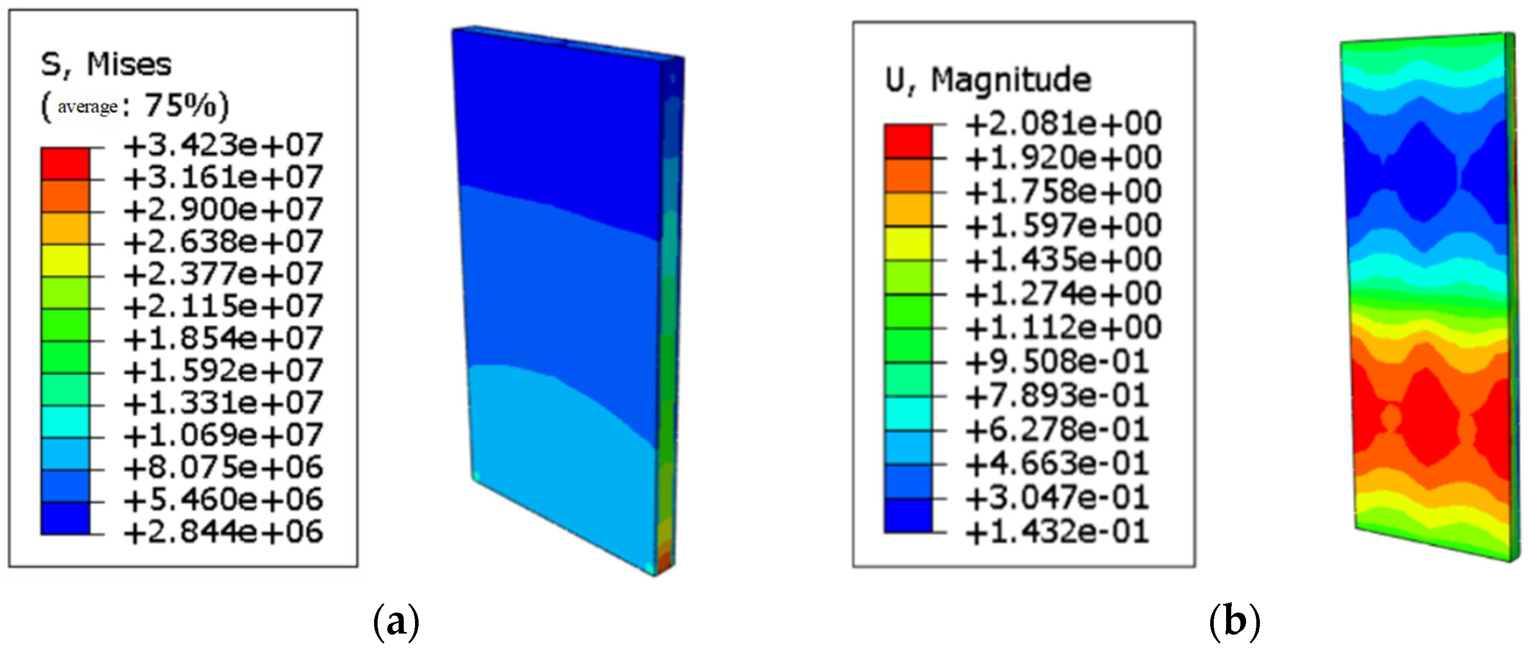
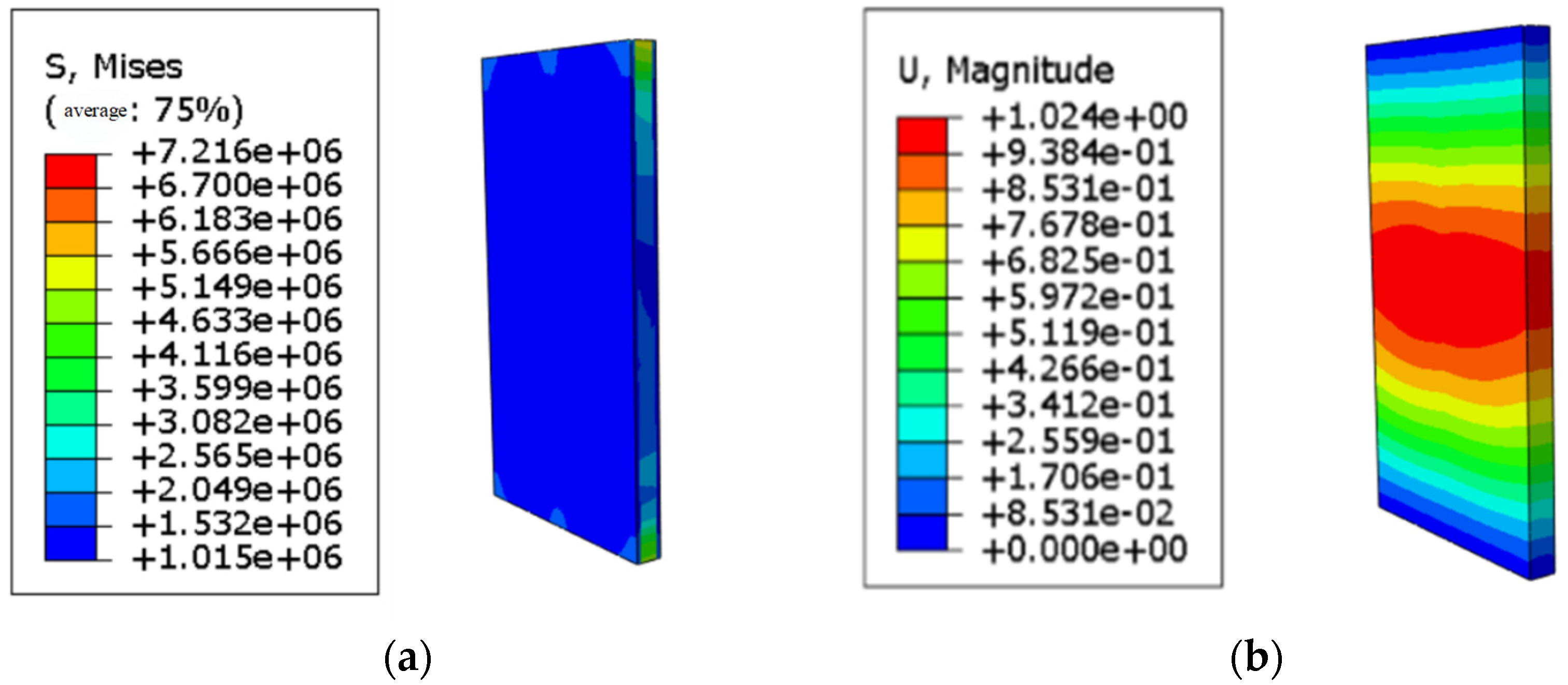
  • The simulation results indicate that the Mises stress at the bottom of the wall reaches 34.25 MPa when a compressive load is applied, meeting the design value of the compressive strength obtained from MOC testing. Under wind load conditions, the maximum Mises stress reaches 7.216 MPa, which does not exceed the ultimate strength, indicating that the board can function normally under gusty wind loads. The maximum deflection of the wall under wind load is 1.024 mm, which can align with the normal use requirements. This suggests that the wall modules made from this material can be applied as a load-bearing wall in buildings up to two stories high.
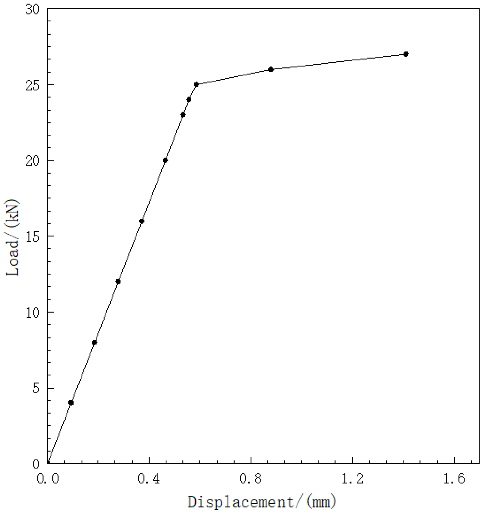
  • The analysis of lateral force resistance reveals that structural stiffness decreases when the lateral concentrated force reaches 29 kN. Considering the material characteristics of the fiber-reinforced bamboo board, the yield displacement is defined as the maximum displacement at the end of the elastic stage, with a value of 0.6773 mm. The ultimate lateral resistance of the fiber-reinforced bamboo wallboard is 29 kN, indicating significant lateral force resistance.
The glass fiber-reinforced bamboo board proposed in this study offers advantages such as energy saving, environmental protection, fire resistance, and excellent mechanical properties. Compared to existing glass fiber-reinforced wood board, the mechanical properties of the glass fiber-reinforced bamboo board proposed are strong. In order to prevent a shortage of wood, the study of glass fiber-reinforced bamboo board proposed is of interest. This material can be directly used to make the wall modules for buildings below two floors. However, as a floor module, it needs to be designed by professional designers. Additionally, the board can be applied in other engineering scenarios as a green and low-carbon board.

Author Contributions

Conceptualization, B.J. and H.W.; methodology, B.J. and H.W.; validation, B.J. and H.W.; investigation, H.W.; resources, B.J.; data curation, H.W.; writing—original draft preparation, H.W.; writing—review and editing, B.J.; visualization, H.W.; supervision, B.J.; project administration, B.J.; funding acquisition, B.J. All authors have read and agreed to the published version of the manuscript.

Funding

This research was funded by the Natural Science Foundation of Hainan Province (No. 123MS006) and the National Key Research Program of China (No. 2019YFD1101004).

Institutional Review Board Statement

Not applicable.

Informed Consent Statement

Not applicable.

Data Availability Statement

The data presented in this study are available upon request from the authors. The data are not publicly available due to privacy.

Conflicts of Interest

The authors declare no conflicts of interest.

References

  1. Li, K.; Zhou, Y.; Huang, X.; Xiao, H.; Shan, Y. Low-carbon development pathways for resource-based cities in China under the carbon peaking and carbon neutrality goals. Environ. Sci. Pollut. Res. 2024, 31, 10213–10233. [Google Scholar] [CrossRef] [PubMed]
  2. Chen, W.; Yang, S.; Zhang, X.; Jordan, N.D.; Huang, J. Embodied energy and carbon emissions of building materials in China. Build. Environ. 2022, 207, 108434. [Google Scholar] [CrossRef]
  3. Wang, Z. Test and Analysis of Mechanical Properties of Full-Scale Components of Fiber-Reinforced Wood Substrate. Master’s Thesis, Southwest Jiaotong University, Chengdu, China, 2019. [Google Scholar]
  4. Zhang, W.; Sun, X.; Liu, C. Experimental study on seismic performance of fiber-reinforced cladding wood-based wallboard. China Civ. Eng. J. 2018, 51, 85–91. [Google Scholar]
  5. Pi, P. Experimental and Application Research on Fiber-Reinforced Wood-Based Components. Master’s Thesis, Xihua University, Chengdu, China, 2018. [Google Scholar]
  6. Kymäläinen, M.; Belt, T.; Seppäläinen, H.; Rautkari, L. Decay resistance of surface carbonized wood. Materials 2022, 15, 8410. [Google Scholar] [CrossRef] [PubMed]
  7. Musselman, E.S.; Dinehart, D.W.; FitzPatrick, T.; Zabel, R. Behavior of Cellulosic Fiber Board Wood-Frame Shear Walls with and without Openings under Cyclical Loading. Buildings 2024, 14, 3097. [Google Scholar] [CrossRef]
  8. Peng, L.; Searchinger, T.D.; Zionts, J.; Waite, R. The carbon costs of global wood harvests. Nature 2023, 620, 110–115. [Google Scholar] [CrossRef]
  9. Borowski, P.F.; Patuk, I.; Bandala, E.R. Innovative industrial use of bamboo as key “Green” material. Sustainability 2022, 14, 1955. [Google Scholar] [CrossRef]
  10. Hailemariam, E.K.; Hailemariam, L.M.; Amede, E.A.; Nuramo, D.A. Identification of barriers, benefits and opportunities of using bamboo materials for structural purposes. Eng. Constr. Archit. Manag. 2023, 30, 2716–2738. [Google Scholar] [CrossRef]
  11. Adier, M.F.V.; Sevilla, M.E.P.; Valerio, D.N.R.; Ongpeng, J.M.C. Bamboo as sustainable building materials: A systematic review of properties, treatment methods, and standards. Buildings 2023, 13, 2449. [Google Scholar] [CrossRef]
  12. Sun, X.; He, M.; Li, Z. Novel engineered wood and bamboo composites for structural applications: A state-of-the-art review of manufacturing technology and mechanical performance evaluation. Constr. Build. Mater. 2020, 249, 118751. [Google Scholar] [CrossRef]
  13. Zheng, Y.; Jiang, Z.; Sun, Z.; Ren, H. Effect of microwave-assisted curing on bamboo glue strength: Bonded by thermosetting phenolic resin. Constr. Build. Mater. 2014, 68, 320–325. [Google Scholar] [CrossRef]
  14. Chung, M.-J.; Chang, T.-C.; Chang, S.-T.; Wang, S.-Y. Properties of a formaldehyde-free tannin adhesive and mechanical strength of oriented bamboo scrimber board bonded with it. Holzforschung 2021, 75, 91–100. [Google Scholar] [CrossRef]
  15. Zhang, X.; Zhao, M.; Zhao, E.; Liu, J.; Liu, Q.; Li, S.; Yin, H.; Yang, C.; Li, X. Experimental investigation into mechanical properties of inorganic-bonded bamboo composite for structural applications. Constr. Build. Mater. 2024, 427, 136247. [Google Scholar] [CrossRef]
  16. Soni, A.; Das, P.K.; Hashmi, A.W.; Yusuf, M.; Kamyab, H.; Chelliapan, S. Challenges and opportunities of utilizing municipal solid waste as alternative building materials for sustainable development goals: A review. Sustain. Chem. Pharm. 2022, 27, 100706. [Google Scholar] [CrossRef]
  17. Patil, M.; Boraste, S.; Minde, P. A comprehensive review on emerging trends in smart green building technologies and sustainable materials. Mater. Today Proc. 2022, 65, 1813–1822. [Google Scholar] [CrossRef]
  18. WB/T 1019-2002; Caustic Burned Magnesia for Magnesium Oxychloride Cement Products. Code for Design House: Beijing, China, 2002.
  19. Chen, T.; Wu, Z.; Hu, X.; Aladejana, J.T.; Niu, M.; Liu, Z.; Wei, Q.; Peng, X.; Xie, Y.; Wu, B. Constructing hydrophobic interfaces in aluminophosphate adhesives with reduced graphene oxide to enhance the performance of wood-based boards. Compos. Part B 2020, 198, 108168. [Google Scholar] [CrossRef]
  20. Cao, F.; Qiao, H.; Li, S.; La, S.; Shao, Y. Study on the water resistance of acrylic emulsion/Barley Straw Ash modified magnesium oxychloride cement. Funct. Mater. 2022, 53, 10122–10129. [Google Scholar]
  21. JC/T 681-2005; Mixer for Mixing Mortars. Code for Design House: Beijing, China, 2005.
  22. Yang, Y.; Tan, Y.; Li, Z.; Zhou, G.; Yu, X.; Xu, D.; Yong, Q.; Zhao, H.; Xie, Z. Interaction mechanisms between polycarboxylate superplasticizers and cement, and the influence of functional groups on superplasticizer performance: A review. Polym. Bull. 2024, 81, 10415–10438. [Google Scholar] [CrossRef]
  23. Gu, K.; Chen, B.; Yu, H.; Zhang, N.; Bi, W.; Guan, Y. Characterization of magnesium-calcium oxysulfate cement prepared by replacing MgSO4 in magnesium oxysulfate cement with untreated desulfurization gypsum. Cem. Concr. Compos. 2021, 121, 104091. [Google Scholar] [CrossRef]
  24. GB/T 17671-2021; Test Method for the Strength of Cement Mortar. Code for Design House: Beijing, China, 2021.
  25. Zhou, W.; Ye, Q.; Zhou, Z.; Aladejana, J.T.; Cao, J.; Li, J. A high-strength, water-resistant, flame-retardant magnesium oxychloride cement-based inorganic adhesive achieved through the construction of a supramolecular system. J. Clean. Prod. 2023, 419, 138239. [Google Scholar] [CrossRef]
  26. Zhou, W.; Ye, Q.; Shi, S.Q.; Fang, Z.; Gao, Q.; Li, J. A robust magnesium oxychloride cement wood adhesive via an organic–inorganic hybrid approach. Constr. Build. Mater. 2021, 297, 123776. [Google Scholar] [CrossRef]
  27. Liu, W.; Sun, Y.; Zhang, J.; Li, W.; Wang, L.; Yu, J.; Qin, X. Influence of the H2O/MgCl2 molar ratio on the strength properties of magnesium oxychloride cement solidified soft clay and its associated mechanisms. Constr. Build. Mater. 2023, 393, 132018. [Google Scholar] [CrossRef]
  28. GB/T 8696-2008; Building Decoration Materials Glass Fiber Mesh Cloth. Code for Design House: Beijing, China, 2008.
  29. JC/T 568-2007; Boaeds of Magnesium Oxychloride Cement. Code for Design House: Beijing, China, 2007.
  30. GB/T 7019-2014; Test Method for Fiber Cement Products. Code for Design House: Beijing, China, 2014.
  31. Deng, C. Experimental Study on the Bending and Shear Stress of Fiber-Reinforced Wood-Based Components. Master’s Thesis, Xihua University, Chengdu, China, 2018. [Google Scholar]
  32. Yang, S.-T.; Jing, Q.-Y.; Li, J.; Luo, B.; Liu, H.-G. Study on the preparation and modification mechanism of bamboo composite magnesium oxychloride cement. Bull. Silic. 2019, 38, 3587–3591. [Google Scholar]
  33. JC/T 412.1-2018; Fiber Cement Flat Sheets—Part 1: Non-Asbestos Fiber Cement Flat Sheets. Code for Design House: Beijing, China, 2018.
  34. Wang, H.; Zhang, J.; Wang, W.; Wang, Q. Research progress in fiber-reinforced wood-plastic composites. Sci. Silvae Sin. 2016, 52, 130–139. [Google Scholar]
  35. GB50009-2012; Load Code for the Design of Building Structures. Code for Design House: Beijing, China, 2012.
  36. GB50010-2015; Code for Design of Concrete Structures. Code for Design House: Beijing, China, 2015.
  37. GB 50005-2017; Design Standard of Wood Structures. Code for Design House: Beijing, China, 2017.
Figure 1. MOC prism specimen.
Applsci 15 05288 g001
Figure 2. Performance test of MOC specimen: (a) flexural strength test of MOC specimen; (b) compressive strength test of MOC specimen.
Applsci 15 05288 g002
Figure 3. Mechanical properties of MOC doped with FG: (a) flexural strength of MOC mixed with FG; (b) compressive strength of MOC mixed with FG.
Applsci 15 05288 g003
Figure 4. Structure of fiber-reinforced bamboo composite board: (a) bamboo strip distribution; (b) distribution of fiberglass cloth; (c) MOC distribution; and (d) composite plate sample.
Applsci 15 05288 g004
Figure 5. Folding test of fiber-reinforced bamboo substrate.
Applsci 15 05288 g005
Figure 6. Fiber-reinforced bamboo substrate: (a) size of fiber-reinforced bamboo substrate; (b) plate constraint and load model.
Applsci 15 05288 g006
Figure 7. Stress–strain curves of the materials used in the simulation: (a) bamboo strip; (b) MOC.
Applsci 15 05288 g007
Figure 8. Load–displacement curve of fiber-reinforced bamboo substrate: (a) vertical bamboo fiber direction; (b) follow the direction of the bamboo fiber.
Applsci 15 05288 g008
Figure 9. Distribution chart of flexural stress of fiber-reinforced bamboo substrate: (a) vertical bamboo fiber direction; (b) follow the direction of the bamboo fiber.
Applsci 15 05288 g009
Figure 10. Internal structural dimensions of fiber-reinforced bamboo floor slab: (a) fiber- reinforced bamboo base panel dimensions; (b) grid floor.
Applsci 15 05288 g010
Figure 11. Fiber-reinforced bamboo floor slab: (a) fiber-reinforced bamboo-based floor slabs exert restraint; (b) load applied to fiber-reinforced bamboo floor slabs.
Applsci 15 05288 g011
Figure 12. Performance cloud map of fiber-reinforced bamboo floor slab: (a) stress nephogram of fiber-reinforced bamboo floor slab; (b) grid floor stress nephogram; (c) stress distribution chart of the upper floor cladding panel; and (d) stress distribution chart of the lower floor cladding panel.
Applsci 15 05288 g012
Figure 13. Cloud image of the improved fiber-reinforced bamboo floor: (a) stress distribution chart of the improved fiber-reinforced bamboo floor slab; (b) improved distribution chart stress nephogram.
Applsci 15 05288 g013
Figure 14. Fiber-reinforced bamboo base wallboard: (a) dimensions of wallboard; (b) restraint of wallboards.
Applsci 15 05288 g014
Figure 15. Loading of fiber-reinforced bamboo foundation wallboard: (a) vertical loads applied to wall panels; (b) wind load applied to wall panels.
Applsci 15 05288 g015
Figure 16. Compressive load performance of fiber-reinforced bamboo wallboard: (a) vertical load stress distribution chart of fiber-reinforced bamboo wallboard; (b) displacement distribution chart of fiber-reinforced bamboo wallboard.
Applsci 15 05288 g016
Figure 17. Wind load performance of fiber-reinforced bamboo wallboard: (a) wind load stress distribution chart of fiber-reinforced bamboo wallboard; (b) displacement distribution chart of fiber-reinforced bamboo wallboard.
Applsci 15 05288 g017
Figure 18. Load–displacement curve.
Applsci 15 05288 g018
Table 1. Mass ratio of magnesium oxychloride cement mixed with gypsum.
Sample Numbern (MgO)n (MgCl2·6H2O)n (Water-Resistant Modifier)n (H2O)n (FG)
Z-1-1-02.010.0810
Z-1-1-12.010.0810.2
Z-1-1-22.010.0810.4
Z-1-1-32.010.0810.6
Table 2. Specific data on the mechanical properties of MOC doped with FG.
Dosage of FGMechanical Properties
Flexural Strength/(MPa)Compressive Strength/(MPa)
7 d14 d28 d7 d14 d28 dImmersion in Water 7 d
0%4.354.985.7036.6843.7947.5139.24
10%4.555.266.1437.6944.8949.0841.18
20%4.655.537.3538.3945.1154.2545.66
30%4.315.367.0036.8943.8348.6440.15
Table 3. Material parameter properties.
SampleMaterial Parameter
Modulus of Elasticity (GPa)Poisson’s RatioDensity (kg/m3)Compressive Strength
cu, MPa)
Tensile Strength (σtu, MPa)
Bamboo Strip150.378050165.99
MOC500.2190048.8334.64
Disclaimer/Publisher’s Note: The statements, opinions and data contained in all publications are solely those of the individual author(s) and contributor(s) and not of MDPI and/or the editor(s). MDPI and/or the editor(s) disclaim responsibility for any injury to people or property resulting from any ideas, methods, instructions or products referred to in the content.

