Abstract
Due to the growing popularity of vacuum tube solar collectors and their more esthetically pleasing look, horizontal hot water tanks are increasingly being used in solar hot water systems. In order to improve the thermal performance of a horizontal mantled hot water tank, this work numerically examines the impact of positioning inclination barriers parallel or coincident to one another at varying angles. The main input provided the velocity V = 0.036, 0.073, 0.11, and 0.147 m/s, and analysis were performed for each speed. The study concluded that V = 0.073 m/s was the ideal mains input velocity for each scenario and that raising the speed typically resulted in a lower mains outlet temperature. According to the study’s findings, the tank design with the first obstacle 150 mm away and the two obstacles 100 mm apart achieves the best efficiency. The residential water temperature in this model is 312 K, while the storage water temperature is 309.5 K. In this study, a feed-forward artificial neural network (ANN) model based predictor was designed to estimate the mantle outlet and main outlet temperatures and the temperature of the stored water. Analyses were performed for different network inlet velocities and obstacle combinations, and ANN showed superior performance in estimating temperature parameters.
1. Introduction
Renewable energy sources are constitutionally non-active sources. Because of that, energy storage is one of the most convenient ways to continue to utilize the energy source when the energy source is not active. Furthermore, there is critical inconsistency between supply and demand in energy use. Therefore, different energy consumption tariffs (peak period, non-peak period, daytime etc.) are applied when using energy resources. Energy storage systems can also be used to translocate energy needs during periods when energy consumption is intense and expensive, as energy use is not intense and is cheaper. All types of energy can be stored. Acar has conducted a comparison and rating study among the types of energy storage [1]. It highlighted that thermal energy storage is an extensively used and harvested type among the types of energy storage.
One of the most critical factors in the widespread use of thermal energy storage from past to present is the production and consumption of most of the global energy used as heat. Many operations of thermal energy storage have been made and improved from past to present. The thermal properties of horizontal HWT were studied by Morrison et al. [2]. They enhanced an experimental model of a horizontal mantled HWT for assessing the heat transfer in the inner tank and the flow patterns in the circinate passageways. Andres and Lopez created a TRNSYS model for a solar household hot water system that equated to a horizontal mantled hot water tank [3]. The results of the experiments supported the proposed model. Khalifa and Mehdi [4] improved a one-dimensional numerical model to define the temperature distribution horizontal HWT. They claimed that based on the analysis in the vertical direction, the temperature in the axial and radial directions may be overlooked. Additionally, it was discovered that the vertical distribution in the middle of the tank could be used to calculate the average temperature of the hot water held there. Alizadeh conducted an experimental and numerical investigation on the thermal performance of a horizontal cylindrical tank [5]. They measured the tank’s temperature distribution under various operation circumstances. Additionally, they updated the one-dimensional numerical model and verified it using experimental results. Helwa et al. conducted another investigation using an experimental setup to determine the impact of hot water consumption on temperature distribution in horizontal HWT [6]. They looked into factors influencing thermal stratification in the horizontal HWT and stated that in order to fulfill the necessary load at the necessary temperature during the winter, horizontal HWT had to solely use an electric heater. Kalogirou and Papamarcou modeled a thermosyphon solar water heating system [7]. They used TRNSYS to validate the simple model and conducted an experiment to validate their model.
Using the particle image velocimetry approach, Rosengarten et al. conducted experimental research to describe the flow characteristics in rectangular horizontal mantled HWT [8]. They developed a numerical model to forecast heat transfer. Rosengarten et al. refined a model to define the heat transport in horizontal mantled HWT. In order to determine the net transfer rate, they provided the average Nusselt number correlation, which could be applied to various geometrical and boundary circumstances [9]. The impact of positioning obstructions perpendicular to the direction of flow into a horizontal hot water tank was experimentally examined by Erdemir and Altuntop [10]. According to the study’s findings, the thermal performance of hot water tanks is enhanced when the obstruction is positioned perpendicular to the direction of flow and has a horizontal mantle. In horizontal hot water tanks, Erdemir et al. investigated the impact of positioning two obstructions parallel to the flow direction [11]. The investigation leads to the determination of the first and second principles of thermodynamics, which state that thermal performance is increased when an obstruction is positioned parallel to the direction of flow. Erdemir et al. conducted an experimental investigation to ascertain how the positioning of barriers affected the thermal performance of a horizontal mantled hot water tank [12]. According to their findings, installing barriers in a horizontal mantled hot water tank improved thermal performance and achieved an energy efficiency of more than 95%. Li et al. investigated the thermal behavior of a new mantle solar water tank with vertical inlet and outlet water pipes, both experimentally and numerically. They stated that the dimensionless parameter can well characterize the stratification and thermocline dynamics of the water in the water tank [13]. Researchers reported that the thickness of the thermocline gradually increased as the dimensionless time increased and the mixture in the water tank became denser in the discharge mode. They stated that the dimensionless exergy gradually decreases with the increase in dimensionless time.
Along with PCMs, hot water tanks’ overall efficiency and thermal stratification are greatly influenced by their geometry and design. In their study, Seterah et al. experimentally investigated the effects of different positions of phase change materials (PCM) inside a hot water storage tank [14]. Some PCM cylindrical capsules are intended to be placed in three circular, horizontal perforated plates that resemble baffles.
In their investigation of the effects of tank design on thermal stratification, Bouzaher et al. found that tanks with sharp corners have better stratification than tanks with smooth surfaces [15]. This is explained by the fact that areas with static fluid lose less heat, which is especially important for horizontal designs. Likewise, thermal stratification is crucial for increasing the effectiveness of solar energy systems, according to Krafcik and Peráčková, who also pointed out that stratified tanks naturally create layers of different temperatures, which maximizes energy storage [16]. Furthermore, a focus of recent research has been the incorporation of creative structures and designs into hot water tanks. By optimizing the structure of hot water storage tanks through numerical simulations, Li et al. showed that changes like octagonal water distributors can greatly enhance temperature stratification [17]. For combined heat and power systems, which depend on efficient thermal management, this is essential for optimizing efficiency.
The literature has also discussed the operational diagnostics of hot water tanks. A new diagnostic technique was presented by Obstawski et al. that makes it possible to evaluate the thermal conductivity coefficients in hot water storage tanks while they are in use [18]. This technique improves the design and operating efficiency of these systems by assisting in the identification of possible heat losses and assisting in the understanding of heat transfer dynamics. Numerous studies have emphasized the potential of horizontal hot water tanks as efficient thermal energy storage systems in the context of energy conservation. For example, Vijay et al. presented an economical approach to energy management in low-carbon futures by discussing the function of home hot water tanks in absorbing excess renewable energy [19]. The argument for improving tank designs to improve thermal performance is supported by the findings of Li et al., who showed that temperature stratified water tanks perform better in terms of energy efficiency than totally mixed tanks [20].
The prediction of the thermal behavior of mantle hot water tanks using artificial neural networks is a crucial area of research that combines the principles of thermal dynamics with advanced computational techniques. Mantle hot water tanks are essential components in various systems like solar domestic hot water (SDHW) systems, where efficient heat storage and transfer are paramount. By leveraging artificial neural networks (ANNs), researchers aim to enhance the accuracy and efficiency of predicting thermal behaviors in these tanks. Studies such as Altuntop et al. have delved into analyzing thermal stratification in mantled hot water storage tanks under different water inlet velocities, highlighting the significance of understanding how flow dynamics impact temperature distribution within the tank [21]. Additionally, research by Deng et al. emphasizes the importance of thermal performance assessment and improvement in solar domestic hot water tanks with phase change materials (PCMs) in the mantle, showcasing the practical implications of optimizing tank designs for enhanced thermal efficiency [22].
Furthermore, the application of artificial neural networks extends beyond tank design to encompass broader aspects of thermal systems. Eynard et al. proposed a methodology that integrates multi-resolution analysis and artificial neural networks to forecast outdoor temperature and thermal power consumption in a multi-energy district boiler, showcasing the versatility of ANNs in optimizing energy systems [23]. Similarly, Gelažanskas and Gamage explored the use of ANNs in predicting hot water consumption in dwellings, demonstrating the adaptability of these networks in forecasting energy demand profiles [24]. These studies collectively underscore the diverse applications of artificial neural networks in predicting thermal behaviors across various domains, emphasizing their efficacy in enhancing predictive capabilities and optimizing system performance. Moreover, the integration of artificial neural networks with experimental data has been a focal point in research endeavors. Afrand et al. investigated the effects of nanoparticles and temperature on the thermal conductivity of water using ANNs and experimental data, showcasing the synergy between computational modeling and empirical observations [25]. Additionally, Sadeghzadeh et al. utilized ANNs to predict the thermo-physical properties of nanofluids, highlighting the role of artificial intelligence in advancing predictive modeling in complex thermal systems [26]. Öcal et al. studied an artificial neural network model and mathematical correlations were created using experimental data to forecast thermal conductivity as a function of temperature and concentration [27].
These studies underscore the significance of combining theoretical frameworks with empirical data to enhance the accuracy and reliability of thermal predictions, showcasing the interdisciplinary nature of research in this field. Furthermore, the development of artificial neural network models for predicting various parameters in thermal systems has been a prevalent theme in recent research. Alrumah and Ertekin focused on predicting water saturation around wells using ANNs, demonstrating the applicability of these networks in geotechnical engineering contexts [28]. Similarly, Garud et al. utilized artificial neural network models to predict thermal performances of thermoelectric generators for waste heat recovery, showcasing the versatility of ANNs in diverse thermal applications [29]. These studies highlight the broad spectrum of predictive modeling enabled by artificial neural networks, emphasizing their utility in forecasting complex thermal behaviors and optimizing system efficiencies.
In conclusion, the utilization of artificial neural networks for predicting the thermal behavior of mantle hot water tanks represents a cutting-edge approach that amalgamates computational intelligence with thermal dynamics. By leveraging the predictive capabilities of ANNs, researchers can enhance the efficiency, accuracy, and optimization of thermal systems, ranging from solar hot water tanks to energy distribution networks. The interdisciplinary nature of this research, as evidenced by studies across geology, materials science, and energy systems, underscores the broad applicability and significance of artificial neural networks in advancing predictive modeling in thermal engineering.
An examination of the literature so far reveals that no research has been carried out on the thermal conductivity of a horizontally jacketed hot water tank with an obstruction inside. This study aims to close many gaps in the literature at the same time and predict the temperature outputs obtained from numerical analysis with the developed ANN. When considered from all these perspectives, the study contributes to the literature in many ways. This study can be considered as a pioneering study on artificial neural networks in terms of increasing the thermal performance of hot water tanks of horizontal mantle tanks.
2. Materials and Methods
2.1. The Studied Tank Model
In this study, a horizontal hot water tank, which is widely used in our country and in the world, is preferred. A schematic of the horizontal mantled hot water tank is shown in Figure 1. As seen from Figure 1, there is an annular volume called mantle above the volume on which the hot water is stored. The heat transfer fluid from the collector passes through an annular volume and transfer the heat energy to the cold water in the storage volume. Mantle hot water tanks are also called mantle heat exchangers. Antifreeze solution is generally used as the heat transfer fluid in mantle and collector conversion in solar water heating systems. Thus, it can be used in winter conditions in the tank and protects the system against freezing.
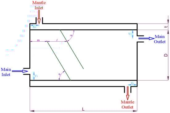
Figure 1.
Schematic of the horizontal mantled hot water tank.
As seen from Figure 1, the inner diameter of the tank is 400 mm and the diameter is 1000 mm. The mantle cavity is 20 mm. The mantle covers the entire inner tank. So, the length of the mantle with the tank length is equal. The storage volume of the tank is 196 L.
In this study, obstacles are placed on the inside of the tank to improve the thermal performance of the tank. The obstacles are located at the “m” distance from the tip of the obstacle from the edge of the tank inside the tank and make the “a” angle with the horizontal axis of the tank. The dimensions of the tank, the locations where the obstacles are placed, and the obstacle angles are given in Table 1.

Table 1.
The structural parameters of the horizontal hot water tank.
2.2. Numerical Model and Procedure
The horizontal mantle hot water tank, which is detailed in Figure 1 and Table 1, is modeled numerically. The numerical model was designed in accordance with the experimental system. The model and grid structure of the horizontal hot water tank are shown in Figure 2. During numerical modeling, the solid parts of the tank (tank walls, barriers) were not modeled. In order to achieve more accurate modeling of the flow and heat transfer between the inner tank and the contact surface, the analysis was conducted without incorporating the solid surfaces into the model. Only the volume of the mantle and the volume of the inner tank are modeled. ANSYS Workbench 18 software and sub-modules were used in numerical modeling. Grid independence was applied to make the numerical solution independent from the number of elements. In this context, 30, 20, 15, and 10 mm element dimensions were tried. On account of modeling the heat transfer and flow in the contact surface between the inner tank and the mantle more precisely, 50% lower than the normal element number was used. After the grid independence process, the size of the element was determined as 15 mm. There are approximately 3.8 million elements in the numerical models.
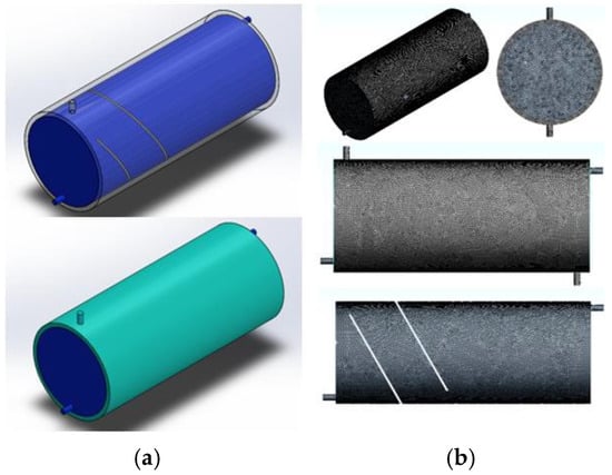
Figure 2.
(a) The model of a horizontal hot water tank for a = 60° and m = 50 mm, l = 200 mm, (b) Grid structure of a horizontal hot water tank.
FLUENT 18 software was used for numerical analysis. The analyzes were performed in a three-dimensional and time-dependent manner for a period of 120 min. The impact on the results of the time step is very important in time-dependent analysis. Thus, 0.25, 0.5, 1, 1.5 s time steps were tried, and the results were independent of time step. In view of the fact that the time steps that are less than 0.5 s do not change the results much, the time step is assumed to be 0.5 s. The mantle and mains inputs are “velocity inlet” and the outputs are set to “pressure outlet”. The outer surfaces of the tank are considered adiabatic. Different turbulence models have been tried to solve turbulence effects. The best solution among these models is the standard k-w turbulence model. SIMPLE algorithm was used during the analysis. Figure 2 shows the numerical model and grid structure for the horizontal tank. Water was used for working fluid. The velocity inlet boundary conditions were applied to the mantle entrance and the main entrance. The mantle outlet and main outlet ports were defined as pressure outlets. Studied inlet and boundary conditions are given in Table 2.
Table 2.
Boundary conditions of numerical model of horizontal hot water tank.
2.3. Experimental Design and Methodology
The appearance of the experimental system and the schematic of the experimental systems are given Figure 3. In the experimental study, the mains water flow and hot water flow have been adjusted by means of flow meters. Three tests were conducted for the tank, and flow meters were used to set the mains water input velocity Vmain = 0.147 m/s and the mantle inlet velocity Vmantle = 0.147 m/s. The tank was fully filled before the experiments began. Two hours were spent conducting the experiments. The information was recorded during the course of the two hours. The system contains fourteen thermocouples. These thermocouples are positioned at nine distinct locations throughout the tank, as well as at the mains water inlet, the mains water outlet, and the mantle water inlet and outlet.
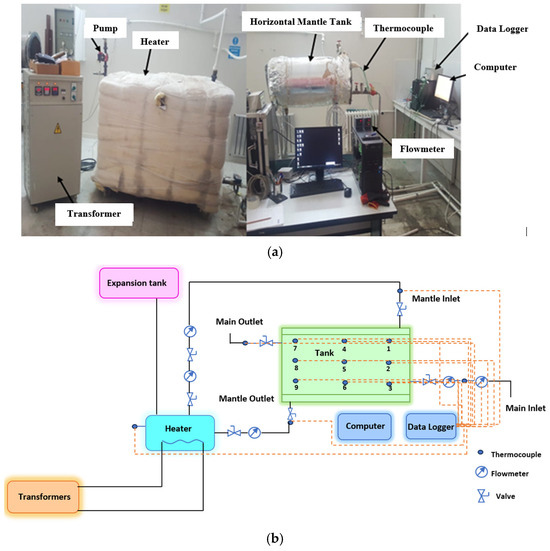
Figure 3.
(a) The experimental system of horizontal hot water tank, (b) Schematic view of the experimental system.
The experimental analysis conducted in a tank with the obstacle positions of a = 60°, m = 100 mm, and l = 100 mm was compared to the numerical analyses. As a result, the precision of the numerical model and process was examined. The temperature of the mantle inlet was set at 70 °C. The temperature at the primary inlet was about 20 °C. Thermocouples inserted into the tank were used to measure the change in the temperature of the stored water after two hours. After two hours, the temperature of the stored water was around 32 °C. The temperature was roughly 305 K. When the main inlet velocity was V = 0.147 m/s, the stored temperature value was 304.36 K, according to the numerical analysis results for the obstacle positioned at a = 60°, m = 100 mm, and l = 100 mm. This result shows that numerical analysis is validated by experimental investigation.
After two hours, the main outlet temperature for the obstacle located at a = 60°, m = 100 mm, l = 100 mm tank was 304.12 K. This value is consistent with the findings of the numerical analysis. The experimental and numerical analysis results for the mantle outlet and main outlet temperature for the obstacle positioned at a = 60°, m = 100 mm, and l = 100 mm tank was compared in Figure 4. The experimental study’s main exit temperature was 305.68 K. This value was comparable to the numerically determined value of 303.71 K.
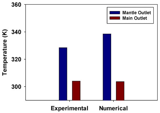
Figure 4.
Experimental and numerical analysis results for the mantle outlet and main outlet temperature for the obstacle placed at a = 60°, m = 100 mm, l = 100 mm tank.
2.4. Thermodynamic Analysis
One of the critical tools in defining the performance of energy transformations and energy storage systems is thermodynamic analysis. Therefore, the first and second laws of thermodynamics have been used in this study. In this condition, energy and exergy balances are written for each case. Some guesses were made to decrease the complication of analyzes during thermodynamic analyzes. These guesses are as follows.
- It was assumed that the physical properties of the water did not change with temperature.
- The flow inside the tank was considered to be frictionless.
- It was accepted that the pump power was zero.
- Heat losses from the tank to the environment were disregarded.
- The ambient temperature was 24 °C.
These assumptions raise energy and exergy efficiency but do not significantly affect the relative values between their states. With these assumptions, critical parameters on the performance of horizontally heated hot water tanks are investigated.
- Energy Analysis:
Energy balance of the horizontal mantled hot water tank can be written as:
𝐸𝑛𝑒𝑟𝑔𝑦 𝑖𝑛𝑝𝑢𝑡 − (𝐸𝑛𝑒𝑟𝑔𝑦 𝑟𝑒𝑐𝑜𝑣𝑒𝑟𝑒𝑑 − 𝐻𝑒𝑎𝑡 𝑙𝑜𝑠𝑠) = 𝐸𝑛𝑒𝑟𝑔𝑦 𝐴𝑐𝑐𝑢𝑚𝑢𝑙𝑎𝑡𝑖𝑜𝑛
This expression may be written as follows:
The expression () is the amount of exergy entering the inner tank, while the expression is the amount of heat exergy taken from the tank.
- Exergy Analysis:
Exergy balance for the horizontal mantled hot water tank can be expressed as:
𝐸𝑥𝑒𝑟𝑔𝑦 𝑖𝑛𝑝𝑢𝑡 − [𝐸𝑥𝑒𝑟𝑔𝑦 𝑟𝑒𝑐𝑜𝑣𝑒𝑟𝑒𝑑 + 𝐸𝑥𝑒𝑟𝑔𝑦 𝑙𝑜𝑠𝑠] − 𝐸𝑥𝑒𝑟𝑔𝑦 𝑑𝑒𝑠𝑡𝑟𝑢𝑐𝑡𝑖𝑜𝑛 = 𝐸𝑥𝑒𝑟𝑔𝑦 𝑎𝑐𝑐𝑢𝑚𝑢𝑙𝑎𝑡𝑖𝑜𝑛
This represents the amount of exergy entering the volume in this statement.
The expression shows the net exergy amount from the storage volume.
(I) represents the amount of exergy caused by irreversibility within the horizontal mantle hot water tank.
Exergy efficiency statement for horizontally heated hot water tank can be written as follows.
Exergy values can be calculated by the following expressions in the inlet and outlet of the tank.
The “i” in this expression represents any entrance or exit of the tank.
3. Numerical Findings
3.1. Effect of Oblique Obstacle Placement on Temperature Distribution in Tank for Different Flow Rates
Using the temperature distribution in the tank to assess the thermal performance of a hot water tank is a basic, simple, and fast method. This is because the temperature of the water in the tank and the amount of stored hot water is directly shown. It is desirable to store water at the highest temperature and volume as possible in a hot water storage tank. The temperature distribution in the tank offers this information directly. At the end of the test period of 120 min, the temperature distribution for the oblique obstacle placement tank is shown in Figure 5, Figure 6, Figure 7, Figure 8, Figure 9, Figure 10 and Figure 11, at a different velocity for each model.
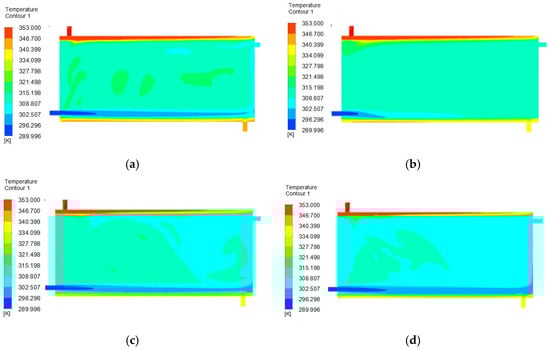
Figure 5.
Temperature distributions for normal (not obstacle) Vmantle = 0.147 m/s (a) Vmain = 0.036 m/s, (b) Vmain = 0.073 m/s, (c) Vmain = 0.11 m/s, (d) Vmain = 0.147 m/s.
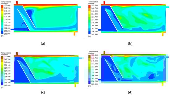
Figure 6.
Temperature distributions for a = 60°, m = 50 mm, l = 100 mm, Vmantle = 0.147 m/s, (a) Vmain = 0.036 m/s, (b) Vmain = 0.073 m/s, (c) Vmain = 0.11 m/s, (d) Vmain = 0.147 m/s.
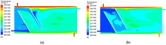
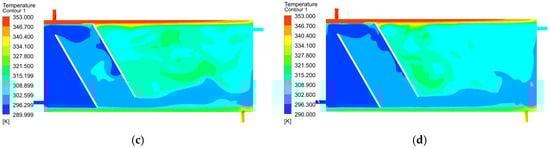
Figure 7.
Temperature distributions for a = 60°, m = 50 mm, l = 200 mm, Vmantle = 0.147 m/s, (a) Vmain = 0.036 m/s, (b) Vmain = 0.073 m/s, (c) Vmain = 0.11 m/s, (d) Vmain = 0.147 m/s.
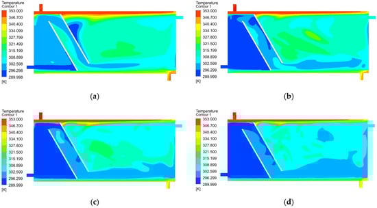
Figure 8.
Temperature distributions for a = 60°, m = 100 mm, l = 100 mm, Vmantle = 0.147 m/s, (a) Vmain = 0.036 m/s, (b) Vmain = 0.073 m/s, (c) Vmain = 0.11 m/s, (d) Vmain = 0.147 m/s.
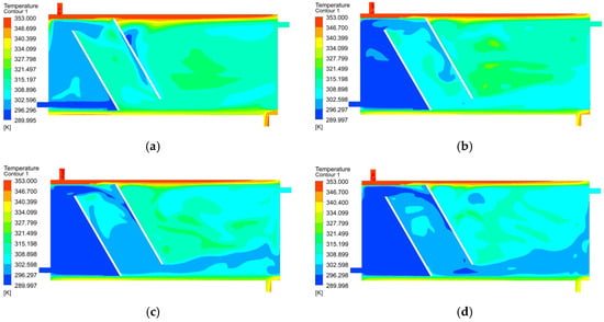
Figure 9.
Temperature distributions for a = 60°, m = 100 mm, l = 200 mm, Vmantle = 0.147 m/s, (a) Vmain = 0.036 m/s, (b) Vmain = 0.073 m/s, (c) Vmain = 0.11 m/s, (d) Vmain = 0.147 m/s.
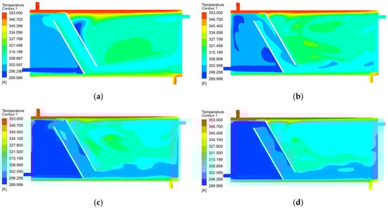
Figure 10.
Temperature distributions for a = 60°, m = 150 mm, l = 100 mm, Vmantle = 0.147 m/s, (a) Vmain = 0.036 m/s, (b) Vmain = 0.073 m/s, (c) Vmain = 0.11 m/s, (d) Vmain = 0.147 m/s.
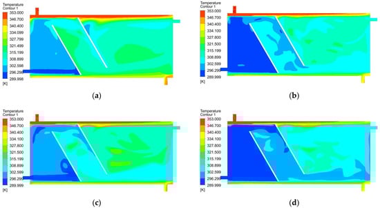
Figure 11.
Temperature distributions for a = 60°, m = 150 mm, l = 200 mm, Vmantle = 0.147 m/s, (a) Vmain = 0.036 m/s, (b) Vmain = 0.073 m/s, (c) Vmain = 0.11 m/s, (d) Vmain = 0.147 m/s.
As can be seen in successive figures; the increase in the storage tank inlet velocity (Vmain) has reduced the domestic water outlet temperature. As a result, considering the temperature distribution in the tank after 120 min, increasing the input velocity negatively affects the temperature distribution within the tank.
3.2. Effect of Oblique Obstacle Placement on the Average Storage Water Temperature in Tank for Different Flow Rates
The average temperature of the water storage in a hot water tank is quite critical, and it is desirable for the temperature of the storage water to be at the highest level. Change over time of the average storage temperature water for all cases is given in Figure 12. Even though it does not give information about the amount of hot water alone, the distribution of the temperature within the tank and the evaluation of the system performance also provides important information.
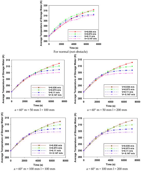
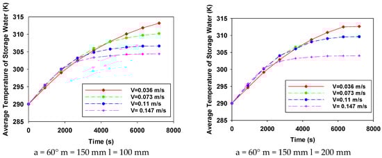
Figure 12.
Change over time of the average storage temperature water for all cases.
In Figure 5, Figure 6, Figure 7, Figure 8, Figure 9, Figure 10 and Figure 11, the variation in the temperature of the hot water stored in the tank over time is seen for all cases. With the exception of V = 0.036 m/s, the water temperature stored at lower velocity is generally higher. If the temperatures in Figure 5, Figure 6, Figure 7, Figure 8, Figure 9, Figure 10 and Figure 11 are compared with the findings obtained from the distribution, using the oblique obstacle, positioning this oblique at the position of m = 100 mm from the mains input and keeping the velocity at V = 0.073 m/s provides the highest amount of water storage in the tank. Both the system’s thermal energy storage performance and user satisfaction will increase with the use of obstacles under the specified conditions.
3.3. Effect of Oblique Obstacle Placement on the Mantle Outlet and Main Outlet Temperature in Tank for Different Flow Rates
Mantle outlet temperature and mains outlet temperature are important performance parameters for mantle hot water tanks. The mantle outlet temperature is important for the thermal efficiency of the hot water tank and the collector. The low mantle output temperature increases the efficiency of the mantle heat exchanger and collectors. In addition, higher temperature changes will change the density of the water and increase the speed of natural circulation. For these reasons, it is generally desirable for the mantle exit temperature to be at the lowest possible level. The usage water outlet temperature is directly related to user satisfaction. Users want hot water at the highest possible temperature and quantity.
In Figure 5, Figure 6, Figure 7, Figure 8, Figure 9, Figure 10 and Figure 11, the variation in the temperature of the hot water storage in the tank over time is seen for all cases. As shown in Figure 13, the storage water temperature obtained at low speed is higher. The storage water temperature decreased as speed increased. The highest main output temperature was a = 60°, m = 150 mm, V = 0.036 m/s. In these cases, the lowest mantle output temperatures were obtained. Except for a = 60°, m = 50 mm, all the obstacle conditions have decreased the mantle outlet temperature and increased the main outlet temperature.
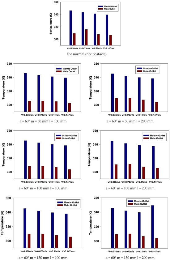
Figure 13.
The value at the end of the 120 min mantle output and main output temperatures for all cases.
4. Artificial Neural Networks
In this study, a feed-forward artificial neural network model was used to predict mantle outlet, main outlet, and stored water temperatures. Temperature values were predicted based on the mains input temperature, mains input velocity, mantle input temperature, and mantle input velocity. The designed ANN consists of one input layer, one hidden layer, and one output layer. There are four linear neurons in the input layer, ten non-linear neurons in the hidden layer, and three non-linear neurons in the output layer. Sixty percent of the data obtained from numerical analysis (52,000 data points for each case) was used for testing, 30% for training, and 10% for validation. The analyses were performed using the neural network toolbox in the MATLAB software (2023b). The number of iterations was set to 1,000,000 and the learning rate was 0.1. The network structure of the designed ANN is given in Figure 14. The modular neural network (MNN) learning algorithm was used to predict the outlet temperatures.
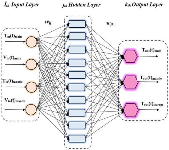
Figure 14.
Schematic representation of feed forward neural network structure.
4.1. Modular Neural Network (MNN)
Adaptive mixtures of local networks are referred to as MNNs. An identical input vector was applied to each local network. Each local network’s contribution to the overall output and the extent of the input space that each network should learn were decided by a gating network. The network output was created by combining the outputs of the local networks in such a way that:
In Equation (7), and where yk are the gating network’s normalized output vector elements and yj are the output of the jth local network, as indicated by:
where uj represents the weighted inputs that the gating network’s jth output unit receives.
4.2. Model Performance
Many definitions of the success of a modeling process rely on the distinction between the output generated by the constructed model and the output produced by the current system, as represented by the model, in response to a specific input sign. Consequently, R square is used to assess model performance. R square is a statistical metric that shows how much of a dependent variable’s variance can be accounted for by an independent variable in a regression model.
The sum of squares of the discrepancy between the model output and the actual system output is the second metric used to assess model performance.
5. Simulation Results
The impacts of the distances between the obstacles and the distance of the first barrier from the network inlet were examined numerically in this research, which involved placing obstacles inside a horizontal jacketed hot water storage tank. The findings obtained from numerical analyses were evaluated based on the temperature distribution within the tank, mantle outlet temperature, main outlet temperature, and the ambient temperature of the water stored within the tank. The temperature of the stored water as well as the temperatures of the mantle and main outlets were estimated using a feed-forward artificial neural network (ANN) model. In Figure 15, Figure 16, Figure 17, Figure 18, Figure 19 and Figure 20, the predicted values of the main and mantle storage temperatures for different obstacle distances are shown.
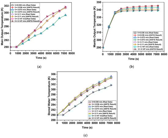
Figure 15.
Prediction results for a = 60°, m = 50 mm, l = 100 mm (a) Tmain, (b) Tmantle, (c) Tstorage.
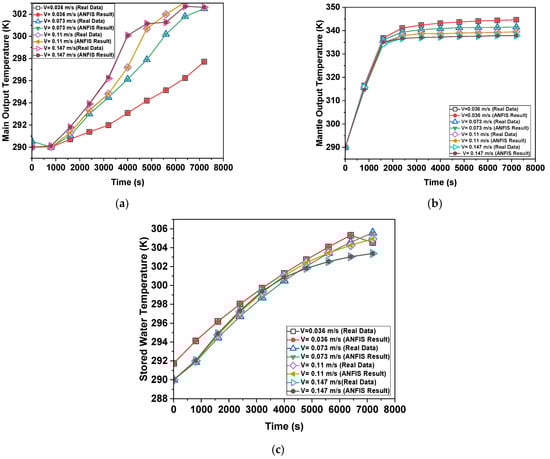
Figure 16.
Prediction results for a = 60°, m = 100 mm, l = 100 mm (a) Tmain, (b) Tmantle, (c) Tstorage.
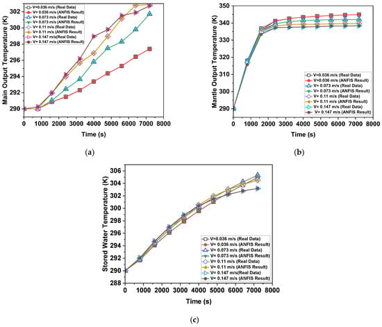
Figure 17.
Prediction results for a = 60°, m = 150 mm, l = 100 mm (a) Tmain, (b) Tmantle, (c) Tstorage.
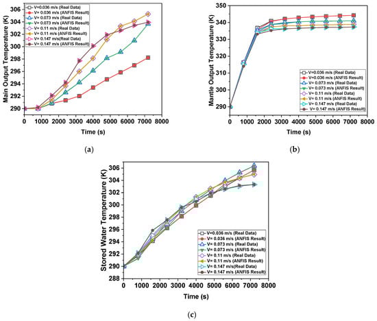
Figure 18.
Prediction results for a = 60°, m = 50 mm, l = 200 mm (a) Tmain, (b) Tmantle, (c) Tstorage.
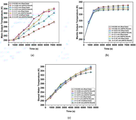
Figure 19.
Prediction results for a = 60°, m = 100 mm, l = 200 mm (a) Tmain, (b) Tmantle, (c) Tstorage.
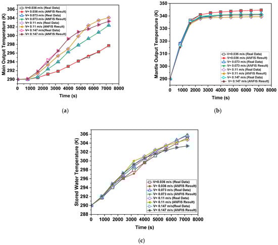
Figure 20.
Prediction results for a = 60°, m = 150 mm, l = 200 mm (a) Tmain, (b) Tmantle, (c) Tstorage.
Actual temperature and model a = 60°, m = 50, l = 100 estimation results are displayed in Figure 15. The MNN technique produced the greatest results for both temperatures. As seen in Figure 16, which displays the model a = 60°, m = 100, l = 100 output temperature estimation results. The best estimate was produced by a structure. The ANN output values for model a = 60°, m = 150, l = 100 were shown to be consistent with the real values in Figure 17. The patterns between the actual and anticipated values for model a = 60°, m = 50, l = 200 are shown in Figure 18. The curves produced by the real data and the MNN structure of ANN share the same form. The ANN output for model a = 60°, m = 200, l = 200 was found to be compatible with the actual temperature measurements, as shown in Figure 19. The ANN output for model a = 60°, m = 100, l = 200 was found to be compatible with the actual temperature measurements, as shown in Figure 19. Analyzing model a = 60°, m = 150, l = 200, the temperature estimation findings in Figure 20 revealed that the ANN structure produced accurate estimates. Table 3 provides the ANN model’s performance values. The error rate is found to be multi-level when the performance criterion values are analyzed. When it comes to temperature prediction, the quick and flexible structure of ANN has demonstrated exceptional performance.
Table 3.
ANN model performance (R square and MSE).
6. Conclusions and Discussion
In this study, in horizontal mantled hot water tanks, two obstacles with 60-degree obstacles parallel to each other were placed in the tank. The distances of the obstacles relative to each other and the effect of the distance of the first obstacle to the main input were investigated numerically and tried to be verified experimentally. Thermal performance, which was provided by obstacles placed at 60 degrees angle parallel to each other, was examined.
For the normal tank, the average temperature of storage, for the main inlet velocity V = 0.036 m/s, was 315.8 K. As the speed increased, the average temperature of the storage decreased. It was 309.5 K when the main inlet velocity was V = 0.147 m/s. Obstacles contributed positively to thermal stratification.
For obstacle position a = 60 °, m = 50 mm, l = 100 mm tank, the stored water temperature was 312.26 K when the main inlet velocity was V = 0.036 m/s, and 305 K when the V was 0.147 m/s at the end of the two-hour period. For obstacle position a: 60°-m: 50 mm-l: 200 mm tank, the stored water temperature was 312.7 K when the main inlet velocity was V = 0.036 m/s, and 304.5 K when the V was 0.147 m/s at the end of the two-hour period. For obstacle position a = 60°, m = 100 mm, l = 100 mm tank, the average temperature of storage was 312.5 K when the main inlet velocity was V = 0.036 m/s, and 304.36 K when the V was 0.147 m/s at the end of the two-hour period. For obstacle position a = 60°, m = 100 mm, l = 200 mm tank, the average temperature of storage was 313.28 K when the main inlet velocity was V = 0.036 m/s, and 304.26 K when the V was 0.147 m/s at the end of the two-hour period. For obstacle position a = 60°, m = 150 mm, l = 100 mm tank, the average temperature of storage was 313.18 K when the main inlet velocity was V = 0.036 m/s, and 304.42 K when the V was 0.147 m/s at the end of the two-hour period. For obstacle position a = 60°, m = 150 mm, l = 200 mm tank, the average temperature of storage was 312.24 K when the main inlet velocity was V = 0.036 m/s, and 304.47 K when the V was 0.147 m/s at the end of the two-hour period. Consequently, a reduction in velocity, increasing the distance between the two obstacles, and increasing the distance of the first obstacle to the main inlet increased the thermal performance.
One of the advantages of MNN is that it reduces the likelihood of inaccuracy, eliminating the necessity for the local linear behavior hypothesis. MNN training also has the benefit of being extremely quick without raising the computing cost of the conventional local learning technique. With MNN used as the learning algorithm for the designed ANN structure, the outlet temperatures of the horizontal jacketed tanks with obstacles placed inside were predicted. When the results were examined, ANN exhibited superior performance in the predictions for all obstacle models. These primary factors make the ANN structure a viable tool for predicting these properties.
As a result, the temperature values obtained for different network inlet speeds and obstacle distances in horizontal jacketed hot water tanks with an obstacle placed inside were predicted using a designed feedforward artificial neural network model. The simulation results have shown that the prediction results of the robust and sensitive ANN are largely consistent with the real values.
In light of the findings obtained from the study, the evaluation of the prognostic capabilities of the ANN developed using different amounts of neurons and input parameters has been conducted. The difference between the planned outputs and the expected results produced by the ANN has been graphically illustrated. Additionally, the performance measures have been meticulously chosen to evaluate the ANN’s effectiveness. Furthermore, it has been shown that ANN serves as an effective resource for engineers, facilitating the analysis of applications associated with thermal performance.
In later studies, improved thermal performance can be attained by augmenting the quantity of obstacles and adjusting the height of the obstacles accordingly, and research can be conducted in this area. The Mix Number serves as an indicator of the temperature distribution within the tank and can be analyzed in the context of dimensionalization. Furthermore, by selecting appropriate training datasets, evaluating the model’s accuracy, and using machine learning techniques alongside practical and computational methodologies, success can be achieved in predicting the thermal performance of the thermal system.
Author Contributions
Conceptualization, A.D. and B.T. (Buket Turgut); methodology, Y.T.; software, A.D. and B.T. (Buket Turgut); validation, Y.T., A.D. and B.T. (Burak Turgut); resources, Y.T.; writing—original draft preparation, A.D. and B.T. (Burak Turgut); writing—review and editing, A.D. and B.T. (Buket Turgut); supervision, Y.T. All authors have read and agreed to the published version of the manuscript.
Funding
This research received no external funding.
Data Availability Statement
The original contributions presented in this study are included in the article. Further inquiries can be directed to the corresponding author.
Conflicts of Interest
The authors declare no conflicts of interest.
Abbreviations
| ANN | Artificial Neural Network |
| HTF | Heat transfer fluid |
| HWT | Hot water tank |
| MNN | Modular Neural Network |
| PCM | Phase change materials |
| SDHW | Solar domestic hot water |
| TRNSYS | Transient System Simulation Tool |
| MSE | Mean Square Error |
| R2 | R Square |
| Symbols | |
| A | Mantle inlet |
| a | Angle of obstruction with horizontal axis |
| B | Mantle outlet |
| C | Main inlet |
| c | Specific heat [J/kg K] |
| D | Main outlet |
| Total energy [kWh] | |
| I | Exergy destroyed [kWh] |
| Energy Accumulation | |
| ΔEx | Energy Accumulation |
| Ex | Total exergy [kWh] |
| m | Distance from obstacle tank edge [kg] |
| Mass flow rate [kg/s] | |
| T | Temperature [K, °C] |
| T∞ | Ambient Temperature [K, °C] |
| Q | Heat transfer [kWh] |
| V | Velocity [m/s] |
| η | Energy efficiency |
| ψ | Exergy efficiency |
| ith | İnput layer |
| jth | Hidden layer |
| kth | Output layer |
| yj | Local networks output |
| yk | Gating networks output |
| gj | Gating networks |
| ui | Weighted inputs |
| xi | Model output |
| yi | Actual system output |
| Subscripts | |
| cv | Control volume |
| i | İnlet |
| o | Outlet |
| loss | Heat loss |
| dest | Destruction |
References
- Acar, C. A comprehensive evaluation of energy storage options for better sustainability. Int. J. Energy Res. 2018, 42, 3732–3746. [Google Scholar] [CrossRef]
- Morrison, G.L.; Nasr, A.; Behnia, M.; Rosengarten, G. Analysis of horizontal mantle heat exchangers in solar water heating systems. Sol. Energy 1998, 64, 19–31. [Google Scholar] [CrossRef]
- Carrillo Andrés, A.; Cejudo López, J.M. TRNSYS model of a thermosiphon solar domestic water heater with a horizontal store and mantle heat exchanger. Sol. Energy 2002, 72, 89–98. [Google Scholar] [CrossRef]
- Khalifa, A.J.N.; Mehdi, M.M. On The Verification Of One Dimensional Heat Flow In A Horizontal Thermosyphon Storage Tank. Energy Convers. Manag. 1999, 40, 961–974. [Google Scholar] [CrossRef]
- Alizadeh, S. An Experimental And Numerical Study Of Thermal Stratification In A Horizontal Cylindrical Solar Storage Tank. Sol. Energy 1999, 66, 409–421. [Google Scholar] [CrossRef]
- Helwa, N.H.; Mobarak, A.M.; El-Sallak, M.S.; El-Ghetany, H.H. Effect of hot-water consumption on temperature distribution in a horizontal solar water storage tank. Appl. Energy 1995, 52, 185–197. [Google Scholar] [CrossRef]
- Kalogirou, S.A.; Papamarcou, C. Modelling of a thermosyphon solar water heating system and simple model validation. Renew. Energy 2000, 21, 471–493. [Google Scholar] [CrossRef]
- Rosengarten, G.; Behnia, M.; Morrison, G. Some aspects concerning modelling the flow and heat transfer in horizontal mantle heat exchangers in solar water heaters. Int. J. Energy Res. 1999, 23, 1007–1016. [Google Scholar] [CrossRef]
- Rosengarten, G.; Morrison, G.L.; Behnia, M. Mixed convection in a narrow rectangular cavity with bottom inlet and outlet. Int. J. Heat Fluid Flow 2001, 22, 168–179. [Google Scholar] [CrossRef]
- Erdemir, D.; Altuntop, N. Improved thermal stratification with obstacles placed inside the vertical mantled hot water tank. Appl. Therm. Eng. 2016, 100, 20–29. [Google Scholar] [CrossRef]
- Erdemir, D.; Altuntop, N. Experimental Investigation on the effect of placing obstacle on flow direction on thermal performance in horizontal mantled hot water tanks. In Proceedings of the 4th Anatolian Energy Symposium, Edirne, Turkey, 18–20 April 2018. [Google Scholar]
- Erdemir, D.; Ateşoğlu, H.; Altuntop, N. Experimental investigation on enhancement of thermal performance with obstacle placing in the horizontal hot water tank used in solar domestic hot water system. Renew. Energy 2019, 138, 187–197. [Google Scholar] [CrossRef]
- Li, Q.; Huang, X.; Tai, Y.; Gao, W.; Wenxian, L.; Liu, W. Thermal stratification in a solar hot water storage tank with mantle heat exchanger. Renew. Energy 2021, 173, 1–11. [Google Scholar] [CrossRef]
- Setareh, M.; Assari, M.R.; Basirat Tabrizi, H.; Jafar Gholi Beik, A.; Raman, F. A new experimental strategy to enhance thermal stratification of solar hot water storage tank using different PCM layouts. Energy Sources Part A Recovery Util. Environ. Eff. 2024, 46, 6428–6443. [Google Scholar] [CrossRef]
- Bouzaher, M.T.; Lebbi, M.; Boualit, H.; Chergui, T.; Laouar, S. Improvement of the thermal stratification inside a solar hot water storage tank during discharging process. Model. Meas. Control B 2018, 87, 78–82. [Google Scholar] [CrossRef]
- Krafcik, M.; Perackova, J. Experimental Measurements of Hot Water Stratification in a Heat Storage Tank. IOP Conf. Ser. Mater. Sci. Eng. 2019, 471, 301–307. [Google Scholar] [CrossRef]
- Li, M.; Bu, B.; Wang, Y.; Zhang, H. Optimizing energy conservation of central heating systems based on temperature stratified water tank. J. Phys. Conf. Ser. 2022, 2358, 012006. [Google Scholar] [CrossRef]
- Li, Y.; Sun, F.; Zhang, Q.; Chen, X.; Yuan, W. Numerical Simulation Study on Structure Optimization and Performance Improvement of Hot Water Storage Tank in CHP System. Energies 2020, 13, 4734. [Google Scholar] [CrossRef]
- Obstawski, P.; Janaszek-Mańkowska, M.; Ratajski, A. Diagnostics of a Domestic Hot Water Storage Tank under Operating Conditions. Processes 2021, 9, 1771. [Google Scholar] [CrossRef]
- Vijay, A.; Bhagavathy, S.M.; McCulloch, M. Potential for domestic thermal storage to absorb excess renewable energy in a low carbon future. In Proceedings of the IEEE Power & Energy Society Innovative Smart Grid Technologies Conference, Washington, DC, USA, 17–20 February 2020. [Google Scholar] [CrossRef]
- Altuntop, N.; Kilik, Z.; Ozceyhan, V.; Kincay, O. Effect of water inlet velocity on thermal stratification in a mantled hot water storage tank. Int. J. Energy Res. 2006, 30, 163–176. [Google Scholar] [CrossRef]
- Deng, J.; Furbo, S.; Kong, W.; Fan, J. Thermal performance assessment and improvement of a solar domestic hot water tank with pcm in the mantle. Energy Build. 2018, 172, 10–21. [Google Scholar] [CrossRef]
- Eynard, J.; Grieu, S.; Polit, M. Predictive control and thermal energy storage for optimizing a multi-energy district boiler. J. Process Control 2012, 22, 1246–1255. [Google Scholar] [CrossRef][Green Version]
- Gelažanskas, L.; Gamage, K.A. Forecasting hot water consumption in dwellings using artificial neural networks. In Proceedings of the IEEE 5th International Conference on Power Engineering, Energy and Electrical Drives (POWERENG), Riga, Latvia, 11–13 May 2015. [Google Scholar]
- Afrand, M.; Esfe, M.; Abedini, E.; Teimouri, H. Predicting the effects of magnesium oxide nanoparticles and temperature on the thermal conductivity of water using artificial neural network and experimental data. Phys. E Low-Dimens. Syst. Nanostructures 2017, 87, 242–247. [Google Scholar] [CrossRef]
- Sadeghzadeh, M.; Maddah, H.; Ahmadi, M.; Khadang, A.; Ghazvini, M.; Mosavi, A.; Nabipour, N. Prediction of thermo-physical properties of tio2-al2o3/water nanoparticles by using artificial neural network. Nanomaterials 2020, 10, 697. [Google Scholar] [CrossRef] [PubMed]
- Öcal, S.; Gökçek, M.; Çolak, A.B.; Korkanç, M. A comprehensive and comparative experimental analysis on thermal conductivity of TiO 2-CaCO 3/Water hybrid nanofluid: Proposing new correlation and artificial neural network optimization. Heat Transf. Res. 2021, 52, 55–79. [Google Scholar] [CrossRef]
- Alrumah, M.; Ertekin, T. Prediction of the water saturation around wells with bottom water drive using artificial neural networks. J. Pet. Gas Eng. 2019, 10, 14–22. [Google Scholar] [CrossRef][Green Version]
- Garud, K.; Seo, J.; Cho, C.; Lee, M. Artificial neural network and adaptive neuro-fuzzy interface system modelling to predict thermal performances of thermoelectric generator for waste heat recovery. Symmetry 2020, 12, 259. [Google Scholar] [CrossRef]
Disclaimer/Publisher’s Note: The statements, opinions and data contained in all publications are solely those of the individual author(s) and contributor(s) and not of MDPI and/or the editor(s). MDPI and/or the editor(s) disclaim responsibility for any injury to people or property resulting from any ideas, methods, instructions or products referred to in the content. |
© 2024 by the authors. Licensee MDPI, Basel, Switzerland. This article is an open access article distributed under the terms and conditions of the Creative Commons Attribution (CC BY) license (https://creativecommons.org/licenses/by/4.0/).