Article

Development of Automatic Berthing Support Program for Autonomous Ships

1
Yeosu Safety Operation Center, Korea Maritime Transportation Safety Authority, Yeosu 59735, Republic of Korea
2
Division of Navigation Science, Mokpo National Maritime University, Mokpo 58628, Republic of Korea
3
Department of Computer Engineering, Mokpo National Maritime University, Mokpo 58628, Republic of Korea
4
Training Ship, Mokpo National Maritime University, Mokpo 58628, Republic of Korea
5
Korea e-Navi Information Technology Co., Ltd., Busan 49112, Republic of Korea
*
Author to whom correspondence should be addressed.
Appl. Sci. 2025, 15(1), 228; https://doi.org/10.3390/app15010228
Submission received: 10 November 2024 / Revised: 9 December 2024 / Accepted: 27 December 2024 / Published: 30 December 2024
(This article belongs to the Special Issue Advances in Intelligent Maritime Navigation and Ship Safety)

Abstract

:
Research on autonomous ships has primarily focused on developing response technologies for navigation from pilot station to pilot station. This study developed an automatic berthing support program that calculates the necessary thruster output values for the bow and stern to achieve the desired berthing speed under varying external force conditions, requiring only essential ship information as input. The program determines the thruster output by analyzing the forces and moments acting on the hull during the berthing process. An experimental setup equipped with the automatic berthing support program was installed on a ship. The outputs of the bow thruster (Thruster(F)) and stern tug (Tug(A)) were 300–544 hp on average, whereas the values calculated by the automatic berthing program (Program(F), Program(A)) were 105–131 hp. The calculation results of the automatic berthing support program of the ship were approximately 3–5 times greater than the horsepower values of the thruster and tug used during actual berthing, probably because the actual berthing speed was 0.25–1.13 m/s, which is more than five times higher than the set speed of 0.05–0.15 m/s. The results indicate that the automatic berthing support program is promising for future applications in automatic berthing systems for autonomous ships.

1. Introduction

With the development of information and communication technology and shipbuilding technology, the automation and digital transformation of ships have been accelerated. The development of ship intelligence has become a key driving force in both navigation technology for autonomous ships and automatic berthing technology [1]. Ship control is still one of the important issues considering the automation and intelligence of ships. Moreover, automatic berthing has become an urgent issue within ship intelligence systems owing to its complexity and importance [2]. The ship berthing process involves close interaction between ships, waterways, and docks, as well as a series of complex operations and techniques [3,4]. In this process, automated vessels use their own propulsion systems to achieve automatic berthing, whereas non-automated vessels rely on tugs for the necessary power and control [5,6]. Intelligent vessel berthing technology has evolved from primarily focusing on automation to using a variety of vessel technologies and auxiliary equipment to achieve automatic berthing. These include dynamic collision avoidance technology [7], which uses sensors such as light detection and ranging (LiDAR) and laser rangefinders to obtain the speed, course, and position of a ship and real-time monitoring of other ships and obstacles in the surrounding waters. Local route planning dynamically generates the optimal route to the target dock based on the real-time environment and the current location of the vessel [8]. Additionally, the coordination of detection technologies, path tracking, tug support, and dynamic positioning systems is highly important for automatic berthing in real-life scenarios, relying on the comprehensive application of these technologies [9].
Autonomous ships, utilizing artificial intelligence, the Internet of Things, big data, and heterogeneous sensor integration, can independently perceive and control their surroundings, thereby reducing maritime accidents and improving operational efficiency. This capability has attracted considerable interest for development both domestically and internationally. To enhance the autonomy of autonomous ships, it is essential to develop navigation systems capable of perceiving external conditions, making navigational decisions, and controlling the vessel [10]. Autonomous navigation systems may incorporate automatic berthing and unberthing technologies, allowing ships to dock or undock without assistance from tugs or pilots. In automatic berthing, a ship approaching a pier must recognize the pier and control its approach by accounting for the berthing speed and the influence of external forces.
Research on automatic berthing includes creating models through neural network learning based on nonlinear ship maneuvering data during berthing and comparing these models with simulation results [11,12,13]. Supervised learning requires a diverse and extensive dataset to effectively train the model for optimal performance. In contrast, reinforcement learning does not require pre-prepared data; instead, the agent generates data by interacting with the environment. The agent observes the environmental state and selects appropriate actions accordingly. Lee [14] proposed an automatic berthing system that builds an optimal control policy through trial-and-error interactions with a given environment, using the Proximal Policy Optimization (PPO) algorithm, a type of reinforcement learning, thus eliminating the need for training data. Vo et al. [15] proposed a path-planning algorithm for automatic berthing based on deep reinforcement learning, utilizing maneuvering simulations. Shimizu et al. [16] trained and evaluated control policy neural networks by combining supervised and reinforcement learning in a simulator designed for a specific harbor geometry under various wind and initial conditions. They found that the proposed method achieved higher success rates and reduced safety risks compared to naive supervised learning and reinforcement learning.
Although neural network-based automatic berthing systems show good performance, they require a large amount of training data to achieve this level of accuracy. Berthing data for diverse situations, such as various ship types, berthing processes, and external environmental conditions, are generally difficult to obtain. Additionally, while reinforcement learning-based automatic berthing systems can produce results solely based on data obtained through interactions with the environment—without requiring a ship’s dynamic mode—they need numerous attempts and a large volume of data, which presents a risk of failure during the learning process. Furthermore, models developed using neural networks and reinforcement learning are often validated in limited experimental environments, which may not fully reflect real-world berthing conditions. Ultimately, to achieve automatic berthing, it is necessary to calculate thruster output values by considering external forces and berthing speed.
Between 2018 and 2019, Mitsui E&S Shipbuilding Co., Ltd. (MES-S) (Tokyo, Japan), Mitsui O.S.K. Lines, Ltd. (MOL) (Tokyo, Japan), Tokyo University of Marine Science and Technology (TUMST), Akishima Laboratories (Mitsui Zosen) (Tokyo, Japan), and MOL Ferry conducted automatic berthing operations using a virtual pier in open water, with the training ship “Shioji Maru” [17]. In 2022, the project team announced the success of an actual demonstration test of their jointly developed auto berthing and unberthing system, which was equipped on the car ferry “Sunflower Shiretoko” [18]. Also, in 2022, MOL completed the world’s first containership sea trial for unmanned docking and undocking, with the 1870 DWT containership “Mikage” [19]. In 2018, Rolls-Royce and Wartsilia announced significant achievements with automatic berthing control systems. Rolls-Royce successfully demonstrated automatic berthing with its developed autonomous navigation system, with no crew intervention, on the fully autonomous 53.8 m car ferry “Falco” [20]. Wartsilia successfully conducted the world’s first autodocking test on the 83 m car ferry “Folgefonn” [21]. In 2019, MacGregor, part of Cargotec, and Kongsberg Maritime have entered into an agreement where MacGregor will deliver an automated mooring system for Yara Birkeland. This will enable mooring operations to be undertaken without human intervention and supports effective operation of the fully electric, zero-emission vessel [22]. In the same year, Volvo Penta released their assisted docking system for boat docking, designed to mitigate the effects of wind and current, and to improve maneuvering control in tight spaces [23].
This study, therefore, proposes an automatic berthing support program that calculates the required thruster output values by taking into account external forces and turning moments acting during the berthing process, as well as the ship’s relative position, heading, and speed, to ensure safe berthing. The program’s performance was verified through full-scale experiments.

2. Methods

2.1. Forces Acting on the Hull During Berthing

When a ship berths at a pier, external forces such as wind and current can cause hull drift or rotation. These effects are primarily due to wind pressure acting on the upper surfaces and fluid forces on the lower surfaces, resulting from the current and lateral movement of the ship. These forces generate moments that rotate the bow relative to the hull’s center of gravity.

2.1.1. Wind Pressure and Wind Moment

The wind pressure ( F W ) acting on the hull during berthing is typically calculated based on the wind-exposed area using Hughes’ empirical formula, as shown in Equation (1), which considers wind direction and angle.
F W = 1 2 ρ a C a A T · c o s 2 θ + A L · s i n 2 θ V a 2 1 1000 ,
where FW represents the wind pressure, ρ a represents the air density, C a represents the wind pressure coefficient, A T represents the frontal wind-exposed area, A L represents the lateral wind-exposed area, θ represents the relative wind direction, and V a represents the wind speed.
Although the wind pressure coefficient is determined through wind tunnel experiments, this study used the wind pressure coefficients for each ship type proposed by Inoue, as shown in Figure 1 [24]. The lateral component of wind pressure creates a turning moment around the hull’s center of gravity, rotating the bow. The center of wind pressure ( a ) can be approximated by Equation (2), and the wind moment ( M W ) can be calculated using Equation (3).
a = 0.291 + 0.0023 θ L ,
M W = F W · s i n θ · 0.5 L a ,
where MW represents the wind moment, FW represents the wind pressure, θ represents the relative wind direction, and L represents the length overall (LOA).

2.1.2. Current Pressure and Current Moment

The current pressure acting on the hull during berthing is a combined effect of the current-induced pressure ( F C ) and the pressure due to berthing speed ( F U ), as indicated in Equation (4). The resulting current moments ( M C , M U ) are calculated using Equation (5).
F C = 1 2 ρ w C y c L B P d V c 2 1 1000 , F U = 1 2 ρ w C y c L B P d U 2 1 1000 ,
M C = 1 2 ρ w C m c L B P 2 d V c 2 1 1000 , M U = 1 2 ρ w C m c L B P 2 d U 2 1 1000 ,
where FC represents the current-induced pressure, FU represents the pressure due to berthing speed, MC represents the current-induced moment, MU represents the moment due to berthing speed, ρ w represents the seawater density, C y c represents the lateral current force coefficient, C m c represents the current moment coefficient, L B P represents the waterline length, d represents the draft, V c represents the current speed, and U represents the berthing speed.
The lateral current force coefficient considerably varies with the depth-to-draft ratio (h/d), requiring a greater force to move the hull laterally as the UKC decreases. The Oil Companies International Marine Forum (OCIMF) conducted model tests on tankers and presented the corresponding lateral current force coefficients, as shown in Figure 2 [25]. Additionally, Inoue [24] proposed formulas for calculating the lateral current force and moment coefficients for VLCCs, with adjustments of 90% (LNG carriers), 85% (container ships), and 75% (PCC) for other ship types. This study used the lateral current force and moment coefficients proposed by Inoue [24].
C y c = 0.75 h d 0.9 + 1 s i n β , C m c = 0.075 h d 0.9 + 1 s i n 2 β ,
where Cyc represents the lateral current force coefficient, Cmc represents the current moment coefficient, h represents the water depth, d represents the draft, and β represents the incident angle.

2.1.3. Frictional Force

When current acts laterally on the hull, it generates lateral current pressure, whereas when it acts longitudinally, it applies frictional force on the underwater surface area of the hull. Frictional force ( F F ) is calculated using Equation (7), and the frictional resistance coefficient is obtained from the Schoenherr curve and the ITTC 1957 model-ship correlation curve based on the Reynolds number [26]. Additionally, the wetted surface area ( S ) is calculated using Equation (8) and applied in Equation (7).
F F = 1 2 ρ w C f S V c 2 1 1000 ,
S = 1.7 d + C b B L B P ,
where F F represents the frictional force, ρ w represents the seawater density, C f represents the frictional resistance coefficient, S represents the wetted surface area, V c represents the current speed, d represents the draft, C b represents the block coefficient, B represents the beam, and L B P represents the waterline length.

2.2. Thruster Output Calculation

2.2.1. Theoretical Calculation

For automatic berthing, as shown in Figure 3, it is necessary to calculate the external forces and moments acting on the ship when berthing at a constant speed ( U ) and determine the corresponding thruster output values. At this stage, the external forces can be divided into longitudinal ( F X ) and lateral ( F Y ) components, as shown in Equation (9), and the total turning moment ( M ) is given by Equation (10).
F X = F X c o s θ + F F c o s β , F Y = F W s i n θ + F C + F U ,
M = M W + M C + M U ,
where F X represents the longitudinal force, F Y represents the lateral force, M represents the total turning moment, M W represents the wind-induced moment, M C represents the current-induced moment, and M U represents the current moment due to ship speed.
Figure 3. Coordinate system.
Applsci 15 00228 g003

2.2.2. Thruster Output Calculation

The force required to control the longitudinal movement of the ship is F X , and the force required for berthing at speed U is F Y (Equation (11)). The output of the bow and stern thrusters, located at distances a and b from the ship’s center of gravity, respectively, and needed to keep the vessel parallel to the pier while considering the turning moment, is given by Equation (12).
F X = ( F T F + F T A ) s i n θ T , F Y = F T L F + F T L A ,
M = a F T L F + b F T L A ,
where F T F represents the bow thruster output, F T A represents the stern thruster output, F T L F represents the lateral component of the bow thruster output, F T L A represents the lateral component of the stern thruster output, a represents the distance between the center of gravity and the bow thruster, and b represents the distance between the center of gravity and the stern thruster.
As a and b are known in advance, F T L F and F T L A are calculated using Equation (13). Considering the external force ( F X ) acting longitudinally on the hull, the thruster output angle is required. Assuming that the output angles of the bow and stern thrusters are the same, the thruster output angle ( θ T ) and outputs ( F T F , F T A ) for the bow and stern required to maintain the hull parallel to the pier and achieve the desired berthing speed under the given external force conditions are provided in Equations (14) and (15), respectively. Additionally, F T F and F T A can be converted to 100 horsepower (hp) per 1.0 ton-force or 100 kW per 1.5 ton-force.
F T L F = M b F Y a b , F T L A = F Y F T L F ,
θ T = atan F X F Y ,
F T F = F T L F   s e c θ T , F T A = F T L A   s e c θ T ,
where F T L F represents the lateral component of the bow thruster output, F T L A represents the lateral component of the stern thruster output, and θ T represents the thruster output angle.

3. Results

3.1. Automatic Berthing Support Program

3.1.1. Thruster Output and Output Angle Calculation Procedure

The process by which the automatic berthing support program calculates the thruster output and output angles based on the environmental input conditions is shown in Figure 4. First, under the specified wind direction/speed and current direction/speed conditions, the program calculates the external forces acting on the hull as the ship berths at the desired speed and then determines the resulting turning moments. Next, the total forces are divided into longitudinal and lateral components. Finally, the program calculates the thruster output and output angles, considering the forces and turning moments acting on the hull.

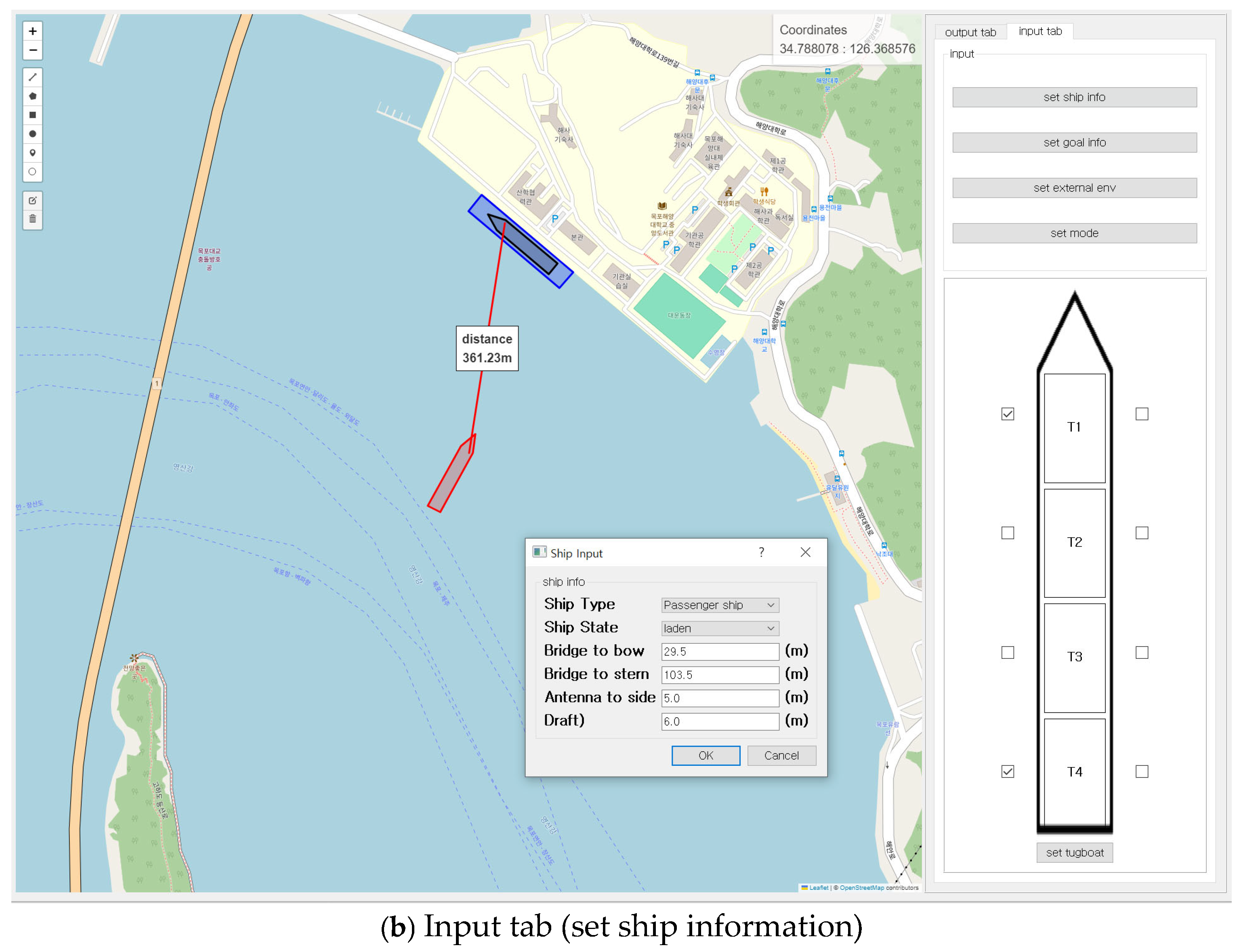
3.1.2. Determining Input Elements

The main input elements required for the calculations to run the automatic berthing support program are classified in Table 1, Table 2 and Table 3. Table 1 includes essential specifications of the ship, such as length overall, waterline length, beam, and draft, along with conditions of the berthing environment. The frontal and lateral wind-exposed areas can be calculated based on the width and height of the superstructure above the waterline. To reflect the actual berthing environment, wind speed, relative wind direction, current speed, incident angle, and berthing speed should be input.
Table 2 lists values determined through intermediate calculations based on the inputs in Table 1, and Table 3 contains constant values that are always applied. Thus, Table 2 and Table 3 provide necessary items for calculations that do not require direct user input in the program.
As the input elements in Table 1 consist of information that may be challenging to obtain quickly from the ship, correlations between these elements and the ship’s type were analyzed using data from 105 ships. This analysis, presented in Table 4, simplifies input, making the program easier for captains and pilots to use.

3.1.3. Development of the Automatic Berthing Support Program

The automatic berthing support program displays the required thruster output values for berthing, real-time distance to the berthing pier, and lateral speed of the ship on the output tab when the input elements are entered in the input tab on the right (Figure 5a).
The input tab is divided into sections for ship-related information (e.g., ship type, length, and draft) (Figure 5b), pier-related information (e.g., pier heading and location), external environmental conditions (e.g., wind direction and speed, current direction and speed, and water depth), and tugboat attachment points. In the future, the information in the input tab could be designed to be automatically received from various equipment installed on the ship.
The program was developed using Python v3.12 and JavaScript, with GUI implemented via PyQt5 v5.15.11 and map visualization using the Folium library. Folium utilizes map data from OpenStreetMap (OSM) [27] to display GPS data in real time on the map. All experiments were conducted in a Windows 11 environment.

3.2. Verification of the Automatic Berthing Support Program

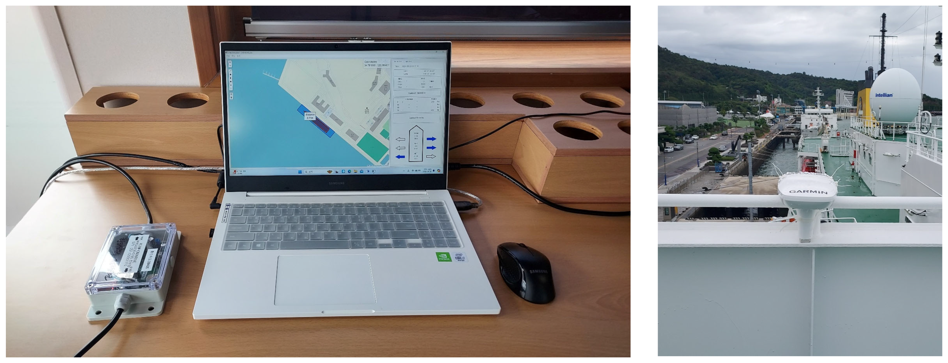
3.2.1. Experimental Condition

The experiment was conducted when Mokpo National Maritime University’s training ship, SEGERO, was berthing at the university after completing a coastal voyage (12 September 2024, around 13:00). During berthing, one tug was positioned at the port stern, along with the use of the bow thruster and main engine. A laptop with the program installed was connected to GARMIN’s MSC 10 Marine Satellite Compass (GARMIN, St. Olathe, KS, USA) to input GPS position, heading, course, and velocity data into the program. The experimental setup is shown in Figure 6, and the specifications of the MSC 10 Marine Satellite Compass are provided in Table 5.
The specifications of the SEGERO are listed in Table 6. The thruster power used for the bow and the tug power at the stern during the approximately 8 min berthing maneuver, until achieving a parallel position with the pier, were compared with the bow and stern thruster output values calculated by the automatic berthing support program. At the time of the experiment, the wind was blowing from 140° at 12 knots, and the current was coming from 130° at 0.1 knots. Given that the current was acting along the bow–stern axis of the ship with the pier directly ahead, a current speed of 0 knots was applied. The pier depth, adjusted for tides, was 9.43 m.
The specifications of the tugboat used during the berthing process are listed in Table 7, and the tug usage record, organized based on voice recordings, is provided in Table 8. Additionally, the specifications of the bow thruster are listed in Table 9.

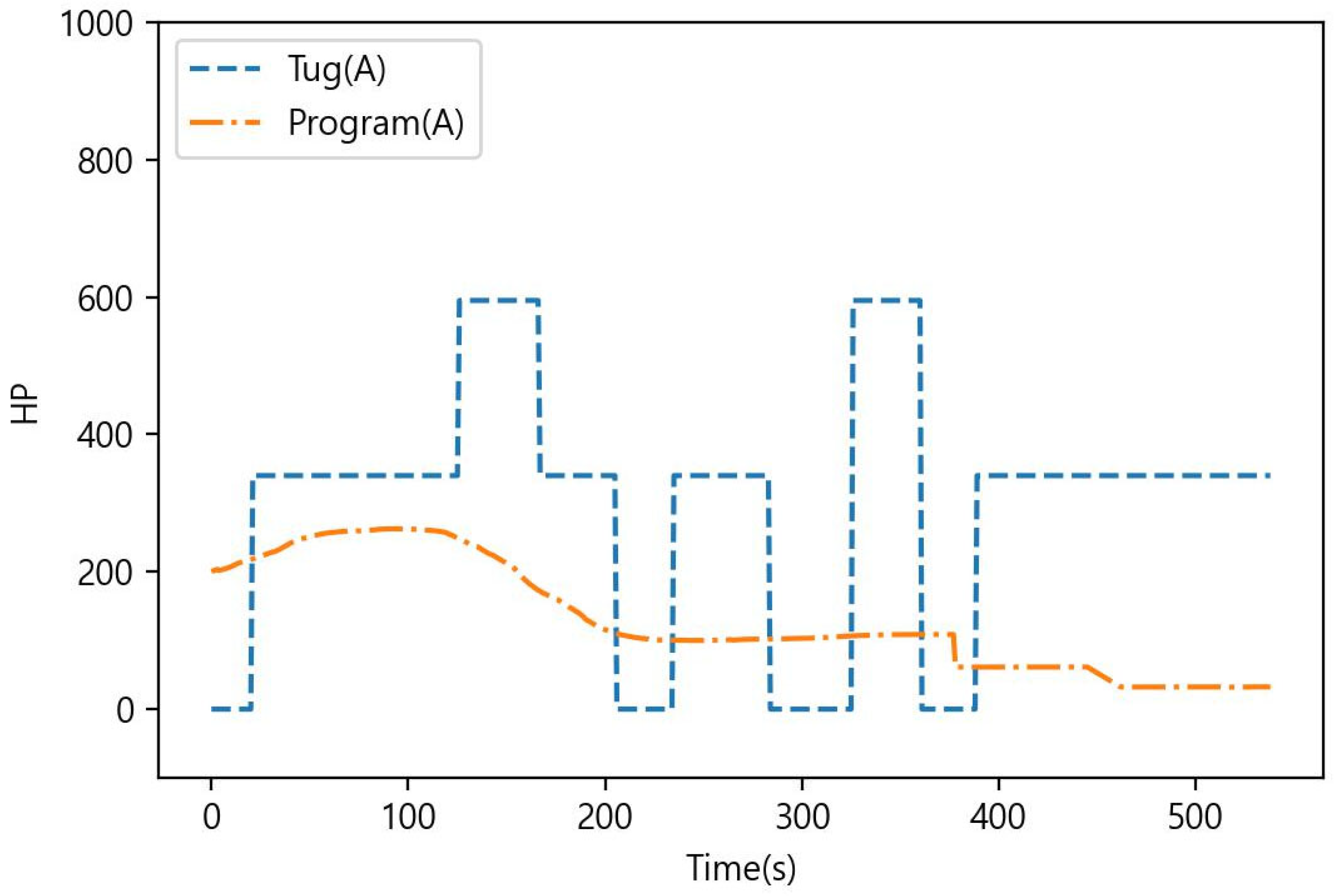
3.2.2. Experimental Results

After passing under Mokpo Bridge, the training ship SEGERO turned to port, approached the pier from behind (Figure 7a), and used a tug and bow thruster to achieve a parallel berth alongside the pier (Figure 7b). The automatic berthing support program not only displays the required thruster (or tug) power for the bow and stern based on external forces but also shows the designated berthing location if pier information is pre-entered, along with the real-time distance to that location.
During the berthing experiment, SEGERO used a bow thruster and a tugboat at the stern to berth. The horsepower of the bow thruster and tugboat, used for approximately 8 min while parallel to the dock, was compared with the horsepower calculated in the ship’s automatic berthing program (indicated as Tugboat Operation, Power in the program).
A time series comparison between the power of the bow thruster of SEGERO (Thruster(F)) and the bow output calculated by the program (Program(F)) is shown in Figure 8. The maximum value of Thruster(F) was 1105 hp, with an average of 544 hp. The maximum value of Program(F) was 183 hp, with an average of 105 hp. Similarly, a time series comparison between the stern tug power of SEGERO (Tug(A)) and the stern output calculated by the program (Program(A)) is shown in Figure 9. The maximum value of Tug(A) was 595 hp, with an average of 300 hp, whereas the maximum value of Program(A) was 263 hp, with an average of 131 hp.

4. Discussion

A program was developed to calculate the required thruster output to maintain the desired berthing speed under varying environmental conditions such as wind and current by analyzing the forces and moments acting on the hull during berthing. Full-scale tests were conducted to validate this program.
During the berthing process, wind pressure, current-induced pressure, and additional pressure due to lateral berthing speed all act on the ship. At the time of docking, wind pressure at the pier’s front aligned with the stern direction, resulting in minimal lateral force. Additionally, the current pressure was near zero, making the primary force the current pressure pushing the ship laterally to align parallel with the pier.
As shown in Figure 10, the berthing speed of a vessel is determined by factors such as the ship’s size, load condition, mooring facilities, weather conditions such as wind, and the presence of tugs. Generally, at a distance of 2–4 times the ship’s beam (B) from the pier, the berthing speed is maintained around 10–15 cm/s, and at 1B, it is kept below 5 cm/s [28].
However, as shown in Table 10, the berthing speed of the test ship during the experiment, calculated based on the time taken relative to the distance from the pier, was found to be 0.25–1.13 m/s, which is 3–7.5 times higher than the standard range (0.05–0.15 m/s). This indicates that the bow thruster and stern tug were used at a higher output than typical standards, resulting in an increased berthing speed. As the automatic berthing support program is configured to calculate tug power based on the standard berthing speed (0.05–0.15 m/s) according to the distance from the pier, a considerable difference—approximately five times—was observed between the actual thruster power used on the ship and the program’s calculated thruster values.
In this experiment, the wind speed was not strong, and the wind direction was nearly aligned with the ship’s bow–stern axis, such that the required output for the tug and thrusters remained below 1000 hp. Additionally, because the actual berthing speed exceeded the program’s intended speed, it was difficult to make a direct comparison with the automatic berthing support program. Furthermore, a limitation of this study is the lack of multiple full-scale tests under various external force conditions.
Technology for automatic ship berthing requires systems to detect hulls or obstacles, track ships in real time to extract dynamic information, and control the hull for automatic berthing.
In 2023, Chen et al. [29] proposed a real-time tracking and anchoring system based on LiDAR, which is a commonly used technology for berthing detection. This system can accurately identify dynamic and static targets and efficiently reposition ships in complex berthing scenarios. They developed a real-time vessel tracking and dynamic berthing information extraction system using 2D LiDAR, which was effectively applied to various berthing scenarios and verified through experiments on the “Yu Kun” training ship at Dalian Port. Qi et al. [30] introduced a method to improve the monitoring of berthing and unberthing conditions by integrating GIS spatial analysis technology. Lu et al. [31] proposed a method for obtaining the ship’s angle using LiDAR’s 3D point cloud data, which has the advantage of accurately determining the ship’s angle during docking, aiding in parallel docking.
Cameras provide visual information about the vessel and dock during the berthing process, helping to identify signs and obstacles in the berthing environment. Kim et al. [32] designed a new artificial intelligence-based vision monitoring system for ship berthing. This system uses high-resolution images to accurately assist ships in adjusting their direction and speed, ensuring safe berthing. Fu [33] developed a ship motion control model to solve the monocular camera motion pose, ultimately addressing the automatic berthing problem. While cameras can provide high-resolution image data, they are limited by lighting conditions and viewing angles. In 2023, Kim et al. [34] developed an autonomous berthing system based on symbol recognition using cameras and LiDAR. In autonomous ship berthing recognition technology (Table 11), cameras and LiDAR can be integrated to effectively detect and track both static and dynamic obstacles during the berthing process, providing spatial and speed information.
An inertial measurement unit (IMU) can provide accurate motion data to support the positioning and control of a vessel during berthing. High-precision location and speed information can also be obtained using accelerometers, gyroscopes, GPS, and other sensors. Hu [35] designed a method to estimate the ship’s operating state based on point cloud matching using LiDAR. The accuracy and stability of the system were verified through comparative testing with an unmanned boat experimental platform based on the Robot Operation System (ROS) and integrated GNSS/IMU navigation.
Technologies such as LiDAR and cameras are used to detect hulls or obstacles, whereas high-precision location and speed information is provided by accelerometers, gyroscopes, GPS, and other sensors. The automatic berthing support program proposed in this study recognizes and displays docks based on GPS location information and calculates and provides the distance between the ship and the dock. In addition, it calculates and presents, in real time, the output of the tug or thruster needed for safe berthing and unberthing, depending on the ship’s berthing speed and the magnitude of external forces in various external force environments.

5. Conclusions

This study developed an automatic berthing support program that calculates the required bow and stern thruster output to achieve the desired berthing speed under given external force conditions, using only basic ship information, and provides this output to the operator.
The research can be divided into two main parts: program development and verification. For program development, the forces and moments acting on the hull during berthing were analyzed to formulate equations that calculate the necessary thruster output to maintain the desired berthing speed in varying environmental conditions such as wind and current. The program was designed to operate with a minimal set of input elements. The automatic berthing support program was installed on a ship, and during an 8 min berthing maneuver—from approach to parallel alignment with the pier—the actual bow thruster and stern tug power usage was compared with the thruster output values calculated by the program. The bow thruster power based on pitch angle (Thruster(F)) and the stern tug power (Tug(A)) averaged between 300 and 544 hp, whereas the calculated bow and stern thruster power from the automatic berthing program (Program(F), Program(A)) averaged between 105 and 131 hp. The calculated power from the automatic berthing support program was approximately 3–5 times lower than the actual thruster power used during berthing. This discrepancy is likely due to the program being designed for a berthing speed of 0.05–0.15 m/s, whereas the actual berthing speed ranged from 0.25 to 1.13 m/s.
Research on automatic ship berthing is largely divided into two areas: recognition technology, which identifies the pier where the ship will berth, and evaluation of the ship’s movement under various external force conditions to ensure the ship can berth at a safe speed. In this study, we present a method to support ships in docking at an appropriate speed by evaluating hull motion in various external force environments, considering the distance to the dock. In addition, the proposed system recognizes piers by inputting the GPS location of the dock in advance and calculates the distance to the pier in real time, unlike other studies and systems that primarily rely on LiDAR and cameras.
The proposed automatic berthing support program can serve as an auxiliary tool to assist operators in safely berthing a ship by providing real-time data on the required bow and stern thruster output, distance to the pier, and lateral movement speed, all based on simple input elements.
Future full-scale experiments under diverse conditions are needed to enhance reliability. If ship input data could be directly transmitted from onboard equipment to the automatic berthing support program, fully automatic berthing for autonomous ships could become possible.

Author Contributions

Conceptualization, B.-S.K. and C.-H.J.; methodology, B.-S.K., C.-H.J. and D.-H.K.; software, K.K. and H.K.; validation, B.-S.K. and C.-H.J.; formal analysis, B.-S.K.; investigation, B.-S.K.; resources, B.-S.K., C.-H.J., K.K., H.K., J.-S.K. and D.-H.K.; data curation, B.-S.K., C.-H.J. and J.-S.K.; writing—original draft preparation, B.-S.K.; writing—review and editing, B.-S.K. and C.-H.J.; visualization, B.-S.K., C.-H.J., K.K. and H.K.; supervision, C.-H.J.; project administration, B.-S.K. and C.-H.J.; funding acquisition, B.-S.K. and C.-H.J. All authors have read and agreed to the published version of the manuscript.

Funding

This research was funded by the “LINC 3.0 (Leaders in INdustry–university Cooperation 3.0) Project” supported by the Ministry of Education and the National Research Foundation of Korea, 20240056.

Institutional Review Board Statement

Not applicable.

Informed Consent Statement

Not applicable.

Data Availability Statement

The original contributions presented in this study are included in the article. Further inquiries can be directed to the corresponding author.

Conflicts of Interest

Author Dae-Hae Kim was employed by the company Korea e-Navi Information Technology Co., Ltd. The remaining authors declare that the research was conducted in the absence of any commercial or financial relationships that could be construed as a potential conflict of interest.

References

  1. Zhang, S.; Wu, Q.; Liu, J.; He, Y.; Li, S. State-of-the-art review and future perspectives on maneuvering modeling for automatic ship berthing. J. Mar. Sci. Eng. 2023, 11, 1824. [Google Scholar] [CrossRef]
  2. Du, Y.Z.; Zhu, Z.J.; Xie, H.W.; Meng, F.B.; Liu, J. Nonlinear Model predictive control for automatic berthing of the underactuated twin-propeller twin-rudder ship. In Proceedings of the 2021 China Automation Congress (CAC), Beijing, China, 22–24 October 2021; pp. 3543–3548. [Google Scholar]
  3. Kim, K.; Kim, B.; Kim, Y. A study on the optimal tracking control system design for automatic ship berthing. J. Korean Soc. Power Syst. Eng. 2018, 22, 72–80. [Google Scholar] [CrossRef]
  4. Kamil, A.; Allal, A.A.; Melhaoui, Y.; Mansouri, K.; Rachik, M. A comparative analysis of methods related to automatic ship berthing. In Proceedings of the 2019 5th International Conference on Optimization and Applications (ICOA), Kenitra, Morocco, 25–26 April 2019; pp. 1–4. [Google Scholar]
  5. Bui, V.P.; Kawai, H.; Kim, Y.B.; Lee, K.S. A ship berthing system design with four tug boats. J. Mech. Sci. Technol. 2011, 25, 1257–1264. [Google Scholar] [CrossRef]
  6. Lee, D.H.; Huynh, T.; Kim, Y.B.; Park, J.S. Motion control system design for barge-type surface ships using tugboats. J. Mar. Sci. Eng. 2022, 10, 1413. [Google Scholar] [CrossRef]
  7. Xue, Y.Z.; Clelland, D.; Lee, B.S.; Han, D.F. Automatic simulation of ship navigation. Ocean Eng. 2011, 38, 2290–2305. [Google Scholar] [CrossRef]
  8. Higo, Y.; Sakano, M.; Nobe, H.; Hashimoto, H. Development of trajectory-tracking maneuvering system for automatic berthing/unberthing based on double deep Q-network and experimental validation with an actual large ferry. Ocean Eng. 2023, 287, 115750. [Google Scholar] [CrossRef]
  9. Zhang, Q.; Zhang, X.K. A review of research on automatic berthing control for ships. J. Dalian Marit. Univ. 2015, 3, 1–9. [Google Scholar]
  10. KISTEP. Technology Trend Brief; Korea Institute of S&T Evaluation and Planning: Eumseong-gun, Republic of Korea, 2020; pp. 3–11. [Google Scholar]
  11. Hasegawa, K.; Kitera, K. Mathematical model of maneuverability at low advance speed and its application to berthing control. In Proceedings of the 2nd Japan-Korea Joint Workshop of Ship and Marine Hydrodynamics, Osaka, Japan, 28–30 June 1993; pp. 144–153. [Google Scholar]
  12. Tran, V.L.; Im, N. A study on ship automatic berthing with assistance of auxiliary devices. Int. J. Nav. Archit. Ocean. Eng. 2012, 4, 199–210. [Google Scholar] [CrossRef]
  13. Bae, C.H.; Lee, S.K.; Lee, S.E.; Kim, J.H. A study of the automatic berthing system of a ship using artificial neural network. J. Navi. Port Res. 2008, 32, 589–596. [Google Scholar] [CrossRef]
  14. Lee, D. Reinforcement learning-based automatic berthing system. arXiv 2021, arXiv:2112.01879. [Google Scholar]
  15. Vo, A.K.; Mai, T.L.; Yoon, H.K. Path planning for automatic berthing using ship-maneuvering simulation-based deep reinforcement learning. Appl. Sci. 2023, 13, 12731. [Google Scholar] [CrossRef]
  16. Shimizu, S.; Nishihara, K.; Miyauchi, Y.; Wakita, K.; Suyama, R.; Maki, A.; Shirakawa, S. Automatic berthing using supervised learning and reinforcement learning. Ocean Eng. 2022, 265, 112553. [Google Scholar] [CrossRef]
  17. Executive, T.M. Video: Japanese Demonstration of Autonomous Docking System. Available online: https://maritime-executive.com/article/video-japanese-demonstration-of-autonomous-docking-system (accessed on 29 November 2024).
  18. SAFETY4SEA. Watch: World’s First Successful Trail of Auto Berthing and Un-Berthing System. Available online: https://www.marineinsight.com/shipping-news/watch-world-first-successful-demonstration-test-of-auto-berthing-and-un-berthing-system/ (accessed on 29 November 2024).
  19. Executive, T.M. First Autonomous Navigation and Berthing Test on a Containership. Available online: https://maritime-executive.com/article/first-autonomous-navigation-and-berthing-test-on-a-containership (accessed on 29 November 2024).
  20. Rolls-Royce. Rolls-Royce and Finferries Demonstrate World’s First Fully Autonomous Ferry. Available online: https://www.rolls-royce.com/media/press-releases/2018/03-12-2018-rr-and-finferries-demonstrate-worlds-first-fully-autonomous-ferry.aspx (accessed on 29 November 2024).
  21. Corporation, W. World’s First Autodocking Installation Successfully Tested by Wärtsilä. Available online: https://www.wartsila.com/media/news/26-04-2018-world-s-first-autodocking-installation-successfully-tested-by-wartsila-2169290 (accessed on 29 November 2024).
  22. Riviera, Yara Birkeland: Automated Mooring System Selected. Available online: https://www.rivieramm.com/news-content-hub/news-content-hub/yara-birkeland-automated-mooring-system-selected-55176 (accessed on 29 November 2024).
  23. Penta, V. Launching the First Fully Integrated Assisted Docking System. Available online: https://www.volvopenta.com/about-us/news-page/2021/jan/launching-the-first-fully-integrated-assisted-docking-system/ (accessed on 29 November 2024).
  24. Inoue, K. Theory and Practice of Ship Handling; Sanghakdang: Seoul, Republic of Korea, 2013; pp. 149–197. [Google Scholar]
  25. OCIMF (Oil Companies International Marine Forum). Mooring Equipment Guidelines, 3rd ed.; Witherby Seamanship International: Baltimore, MD, USA, 2008; pp. 179–196. [Google Scholar]
  26. SNAK (The Society of Naval Architects of Korea). Ship Resistance and Propulsion; Jisungsa: Seoul, Republic of Korea, 2012; p. 72. [Google Scholar]
  27. OpenStreetMap. Available online: https://www.openstreetmap.org (accessed on 28 November 2024).
  28. Ministry of Oceans and Fisheries. Harbor and Fishery Design Criteria; Ministry of Oceans and Fisheries: Sejong-si, Republic of Korea, 2020; pp. 17–20.
  29. Chen, C.; Li, Y.; Wang, T. Real-time tracking and berthing aid system with occlusion handling based on LiDAR. Ocean Eng. 2023, 288, 115929. [Google Scholar] [CrossRef]
  30. Qi, W.T.; Ying, L.; Chen, C. Spatial state analysis of ship during berthing and unberthing process based on 3D LiDAR. Ocean Eng. 2023, 288, 116067. [Google Scholar]
  31. Lu, X.D.; Li, Y.; Xie, M. Preliminary study for motion pose of inshore ships based on point cloud: Estimation of ship berthing angle. Measurement 2023, 214, 112836. [Google Scholar] [CrossRef]
  32. Kim, H.; Kim, D.; Park, B.; Lee, S. Artificial intelligence vision-based monitoring system for ship berthing. IEEE Access 2020, 8, 227014–227023. [Google Scholar] [CrossRef]
  33. Fu, H.; Huang, Y.; Li, W. Ship berthing motion control based on improved Simulation Localization and Mapping algorithm. In Proceedings of the 2021 4th International Symposium on Traffic Transportation and Civil Architecture (ISTTCA), Suzhou, China, 12–14 November 2021; pp. 233–236. [Google Scholar]
  34. Kim, S.; Jo, H.; Kim, J.; Park, J. Development of an autonomous docking system for autonomous surface vehicles based on symbol recognition. Ocean Eng. 2023, 283, 114753. [Google Scholar] [CrossRef]
  35. Hu, B. LIDAR-Based Unmanned Vessel Berthing and Unberthing Information Sensing Research. Master’s Thesis, Dalian Maritime University, Dalian, China, 2022. [Google Scholar]
Figure 1. Resultant wind pressure coefficient [24].
Applsci 15 00228 g001
Figure 2. Lateral current force coefficient (loaded tanker) [25].
Applsci 15 00228 g002
Figure 4. Calculation procedure.
Applsci 15 00228 g004
Figure 5. Program screen.
Applsci 15 00228 g005aApplsci 15 00228 g005b
Figure 6. Experimental equipment.
Applsci 15 00228 g006
Figure 7. Berthing procedure of SEGERO: (a) approaching and (b) berthing.
Applsci 15 00228 g007
Figure 8. Experimental results (Fore).
Applsci 15 00228 g008
Figure 9. Experimental results (Aft).
Applsci 15 00228 g009
Figure 10. Comparison of berthing speeds according to ship size [28].
Applsci 15 00228 g010
Table 1. Input data.
Input DataUnit
LOAm
LBPm
Breadth (B)m
Draftm
Block coefficient (Cb)-
Transverse projected area (AT)m2
Lateral projected area (AL)m2
Water depthm
Wind speedKnot
Relative wind angleDegree
Current speedKnot
Relative current angleDegree
Berthing speedKnot
Table 2. Fixing data during calculation.
Input DataUnit
Resultant wind pressure coefficient-
Lateral current force coefficient-
Hydraulic moment coefficient-
Wetted surface aream2
Table 3. Fixed data.
Input DataValueUnit
Air density0.125kg·s2/m4
Water density104.6kg·s2/m4
Frictional resistance coefficient0.002-
Table 4. Linear regression between input data.
Ship’s TypeLadenBallast
BCbATALBCbATAL
ContainerLBP/7.220.68B*38.0LBP × 40.0LBP/7.220.63B*38.0LBP × 20.0
BulkLBP/6.010.85B*16.1LBP × 15.0LBP/6.010.80B*29.1LBP × 15.7
TankerLBP/5.410.80B*17.7LBP × 10.0LBP/5.410.75B*30.0LBP × 20.0
PCCLBP/5.880.60B*29.2LBP × 29.9LBP/5.880.52B*34.9LBP × 31.9
LNGLBP/6.120.75B*36.0LBP × 30.0LBP/6.120.70B*36.9LBP × 31.7
PassengerLBP/5.930.55B*13.8LBP × 12.7LBP/5.930.52B*15.0LBP × 15.0
OthersLBP/6.000.70B*20.0LBP × 20.0LBP/6.000.70B*20.0LBP × 20.0
Table 5. Technical specifications of the Marine Satellite Compass.
ParameterInformation
Dimensions (length × width × height)334 × 156 × 66 mm3
Weight810 g
Operation temperature range−15° to 70°
Compass safe distance0 mm
Position accuracy<3 m (CEP95)
Heading accuracy2° RMS
Table 6. Specifications of the SEGERO ship.
CategoryInformation
Gross tonnage (t)9196
Length × breadth × depth (m)133 × 19.4 × 11.05
Transverse projected area (m2)300
Lateral projected area (m2)1430
Table 7. General specifications of the tugboat.
CategoryInformation
Gross tonnage (t)145
Length × breadth × depth (m)27.17 × 8.6 × 3.8
Main engine2 sets × Caterpillar (1700 hp)
Propeller typeAquamaster propeller
Table 8. Tug order records.
TimeOrder
12 September 13:11:23Dead slow/perpendicular push
13:11:44Stop engine
13:12:20Dead slow/perpendicular push
13:14:05Slow/perpendicular push
13:14:46Dead slow/perpendicular push
13:15:25Stop engine
13:15:54Dead slow/perpendicular push
13:16:43Stop engine
13:17:25Slow/perpendicular push
13:18:00Stop engine
13:21:00Dead slow/perpendicular push
13:22:20Stop engine
13:26:00Tug line let go
Table 9. General specifications of the bow thruster.
CategoryInformation
Model3-phase induction motor
Output1000 kW
Propeller diameter1850 mm (4 blades)
Type of propellerForward skewed type
Table 10. Difference between actual and standard berthing speeds.
Time
(h/min)
Distance
from Pier
(m)
Difference
(m)
Actual
Berthing Speed (m/s)
Standard
Berthing Speed (m/s)
13:13285
13:14224611.020.15
13:15156681.13
13:16113430.72
13:1778350.58
13:1850280.47
13:1930200.300.10
13:2015150.250.05
Table 11. Comparison of autonomous berthing sensing technologies.
Sensing TechnologyAdvantagesDisadvantages
LiDAR
-
Real-time vessel tracking and dynamic berthing information extraction.
-
Monitoring of vessel berthing and unberthing conditions.
-
Effectively detects and tracks static and dynamic obstacles only with a camera.
Camera
-
Provides visual information about ship and dock.
-
Identification of signs and obstacles.
-
Supports safe berthing by providing high-resolution image data.
-
Limited by lighting conditions and viewing angle.
-
Effectively detects and tracks obstacles only with LiDAR.
Inertial Measurement Unit (IMU)
-
Control of ship position by providing accurate motion data.
-
Provides high-precision location and speed information using accelerometers, gyroscopes, GPS, etc.
-
Expandable by integrating sensors such as LiDAR, cameras, and GPS.
Automatic Berthing Support Program
-
GPS-based pier recognition and display of distance between ship and pier.
-
Easy identification of docking location by displaying the location on the monitor.
-
Calculates and presents the output of the required tug or thruster in real time according to berthing speed and external force (wind, current).
-
Expandable by integrating sensors such as LiDAR, cameras, and GPS.
Disclaimer/Publisher’s Note: The statements, opinions and data contained in all publications are solely those of the individual author(s) and contributor(s) and not of MDPI and/or the editor(s). MDPI and/or the editor(s) disclaim responsibility for any injury to people or property resulting from any ideas, methods, instructions or products referred to in the content.

