Review

Condensation Flow of Refrigerants Inside Mini and Microchannels: A Review

by
Anıl Başaran
1 and
Ali Cemal Benim
2,*
1
Department of Mechanical Engineering, Engineering Faculty, Manisa Celal Bayar University, 45140 Manisa, Turkey
2
Center of Flow Simulation (CFS), Department of Mechanical and Process Engineering, Düsseldorf University of Applied Sciences, 40476 Düsseldorf, Germany
*
Author to whom correspondence should be addressed.
Appl. Sci. 2024, 14(7), 2988; https://doi.org/10.3390/app14072988
Submission received: 16 February 2024 / Revised: 28 March 2024 / Accepted: 29 March 2024 / Published: 2 April 2024
(This article belongs to the Special Issue Feature Papers in Section 'Applied Thermal Engineering')

Abstract

:
Nowadays, the demand for obtaining high heat flux values in small volumes has increased with the development of technology. Condensing flow inside mini- and microchannels has been becoming a promising solution for refrigeration, HVAC, air-conditioning, heat pumps, heat pipes, and electronic cooling applications. In these applications, employing mini/microchannels in the condenser design results in the working fluid, generally refrigerant, undergoing a phase change inside the mini/microchannels. On the other hand, the reduction in the hydraulic diameter during condensation gives rise to different flow regimes and heat transfer mechanisms in the mini- and microchannels compared to the conventional channels. Therefore, the understanding of fluid flow and heat transfer characteristics during condensation of refrigerant inside mini- and microchannels has been gaining importance in terms of condenser design. This study presents a state-of-the-art review of condensation studies on refrigerants inside mini- and microchannels. The review includes experimental studies as well as correlation models, which are developed to predict condensation heat transfer coefficients and pressure drop. The refrigerant type, thermodynamical performance, and compatibility, as well as the environmental effects of refrigerant, play a decisive role in the design of refrigeration systems. Therefore, the environmental impacts of refrigerants and current regulations against them are also discussed in the present review.

1. Introduction

For a given heat transfer load, increasing the heat transfer surface area per unit volume makes condensers compact. A compact heat exchanger design means more light heat exchangers manufactured with less material. In addition to increasing the heat transfer surface per unit volume, increasing the total heat transfer coefficient also improves heat transfer performance. In a heat exchanger, under constant heat flux conditions, the heat transfer coefficient inside the channel increases as a result of reducing the channel hydraulic diameter. Achieving a high heat transfer rate in small volumes has, indeed, generally been one of the main challenges in heat exchanger design [1,2]. In this scope, mini- and microchannel heat exchangers have been becoming promising designs to meet such challenges due to their outstanding advantages. Micro/minichannel condensers are good options for thermal systems because they have high heat transfer coefficients within the channel and a high ratio of surface area to volume.
With the development of micro-production technologies in the last two decades, traditional condensers are being rapidly substituted with microchannel heat exchangers. The fact that the channel diameter in which the flow occurs in microchannels is very small creates different effects on the flow characteristics, which results in different flow regimes [3]. Condensation is the removal of thermal energy by producing a phase change from vapour to liquid in a system. Condensing flow inside mini and microchannels has been becoming a promising solution for refrigeration, HVAC, air-conditioning, heat pumps, heat pipes, and electronic cooling applications. In these applications, employing mini/microchannels in the condenser design results in the working fluid, generally refrigerant, undergoing a phase change inside the mini/microchannels [4].
As the hydraulic diameter decreases, a different flow regime and heat transfer mechanism emerge in the micro/minichannel than in channels with large cross-sectional areas. During the flow in micro/minichannels, capillary effects become dominant while buoyancy forces lose their effect [3]. In other words, as the channel size decreases, the importance of surface tension relative to gravity increases. For this reason, condensation and evaporation models developed for large channels where gravity and inertial forces are dominant cannot be applied to micro/minichannels. Compared to boiling flows in microchannels, studies on condensation flows have been limited [5]. Therefore, in light of the studies in the literature, it is important to understand the intrachannel phase change mechanisms for micro/minichannel condensers. The first step in understanding condensation flow in micro/minichannels is the characterisation of the condensation flow and determination of the flow regime, which forms the basis of the heat transfer coefficient and pressure drop.
In contrast to conventional condensers, the prevalence of surface tension forces over gravity forces in two-phase flow processes within micro/minichannel condensers has spurred significant growth in recent experimental, theoretical, and computational studies in this field. While a relatively small portion of these studies has been dedicated to understanding condensing flow regimes and heat transfer behaviour in micro/minichannels, especially for HVAC-R systems, they offer valuable insights. This review study includes published studies in the rapidly evolving domain of condensation in micro/minichannels, encompassing experimental, theoretical/empirical, and computational contributions. Therefore, the current study establishes a foundation for future research endeavours. Moreover, the selection of refrigerant, its thermodynamic performance, compatibility, and environmental effects significantly influence the design of thermal systems. Hence, this review study also addresses the environmental effects of refrigerants and the existing regulations governing them.

Environmental Impacts of Refrigerants

Many studies on refrigerant condensation inside micro/minichannels exist in the literature, but they investigate condensation flow, especially for Hydro-Fluoro-Carbons (HFCs), Hydro-Cloro-Fluoro-Carbons (HCFCs), and mixtures of them. It is important to highlight that the existing literature lacks comprehensive investigations that accommodate a broad spectrum of working fluids, mass fluxes, saturation temperature, pressures, channel geometries, and dimensions [6,7]. As stated, previous experimental and numerical investigations have predominantly concentrated on the condensation behaviour of HFCs, HCFCs, refrigerant blends in microchannels. Conversely, eco-friendly refrigerant alternatives align with the mandates of the European Union (EU) F-gas regulation [8], and they are gaining importance. Consequently, knowledge about climate-friendly refrigerants is one of the key topics, similar to heat transfer and fluid flow phenomena of condensation. Therefore, the literature review on the environmental impacts of refrigerants is provided in this section before introducing condensation flow of refrigerants inside mini/microchannels.
Refrigerants can be the primary working fluids in many thermal systems due to their thermodynamic and thermophysical properties, which align with the requirements of thermal systems. Typically, they facilitate heat absorption from one medium and its release into another, primarily through evaporation and condensation processes. However, selecting the appropriate refrigerant involves compromises between conflicting desirable thermophysical properties. Apart from its heat transfer capabilities, a refrigerant must meet numerous other criteria: cost, compatibility, safety, and environmental impacts [9].
The environmental effects of refrigerants are mainly categorised into two impacts: ozone layer depletion and global warming. Refrigerants that contain chlorine and/or bromine atoms, such as halocarbon refrigerants, contribute to ozone layer depletion. While their chemical stability makes them desirable as refrigerants, once released into the atmosphere, they migrate to the upper atmosphere. There, they undergo breakdown processes, with the chlorine component reacting with ozone molecules, thus depleting the ozone concentration. The ozone depletion potential (ODP) of a substance is defined as a measure of its ability, relative to CFC-11 (Chlorofluorocarbon-11), to degrade stratospheric ozone [10].
Another environmental concern about refrigerants is their contribution to global warming. Refrigerants can act as greenhouse gases and exacerbate this issue. The global warming potential (GWP) of a greenhouse gas quantifies its capacity, relative to CO2 (known for its extended atmospheric presence), to retain radiant energy. This metric is often associated with a specific timeframe, such as 100 or 500 years. Regulatory frameworks typically employ the 100-year integrated time horizon (ITH) for assessing such impacts [10].
Table 1 and Table 2 show the ODP and GWP values of pure and refrigerant blends, respectively. Hydrocarbon (HC) refrigerants do not contain chlorine and fluoride in their structures. Therefore, HC refrigerants and blends of these refrigerants do not cause depletion of the ozone layer, and their ODP values are equal to zero (Table 1) [11]. Additionally, it can be seen in Table 2 that the ODP values of refrigerant blends are lower than the ODP values of CFCs. ODP values of zeotropic and azeotropic mixtures consisting of HC and HFC (Hydrofluorocarbon) refrigerants are quite low. According to Table 1, CFCs with long atmospheric lifetimes generally have higher GWP values than other refrigerants. When the GWP values of refrigerants are compared, HC refrigerants such as R290, R600, R600a, and R601a have almost no contribution to global warming compared to halocarbon-type refrigerants (CFC, HCFC). When the GWP values of the refrigerant blends given in Table 2 are examined, it is seen that refrigerant blends generally have a lower GWP value than CFCs. On the other hand, the GWP values of the blends are not negligibly low. Despite this, refrigerant mixtures maintain their importance because the undesirable properties of pure refrigerants, such as toxicity and/or flammability, can be reduced with refrigerant blends. When refrigerants are considered in terms of ozone depletion and global warming, HC refrigerants come to the fore.
Following extensive deliberations and negotiations, the Montreal Protocol was formally adopted in 1987 [14]. This protocol, along with the Vienna Convention for the Protection of the Ozone Layer, is committed to safeguarding the Earth’s ozone layer [15]. With participation from 196 parties, these agreements represent the most extensively ratified treaties in the history of the United Nations. Their collective efforts have resulted in reductions exceeding 97% of global consumption of regulated ozone-depleting substances [16]. With international regulations limiting the use of CFCs and HCFCs, refrigerant blends emerge as potential alternatives to these substances. While CFCs and HCFCs boast favourable thermodynamic properties, only a select few refrigerants can match their performance. Nevertheless, refrigerant blends offer a viable thermodynamic alternative to CFCs and HCFCs while also being environmentally conscious materials.
The Kyoto Protocol, established in Kyoto, Japan, on 11 December 1997, and enforced on 16 February 2005, aims to combat climate change and mitigate global warming [14]. Serving as an international accord associated with the United Nations Framework Convention on Climate Change, its notable aspect lies in imposing mandatory emission reduction targets on 37 industrialised nations and the European community to curb greenhouse gas (GHG) emissions [8]. Fluorinated greenhouse gases (F-gases), primarily HFCs, are widely utilised as refrigerants in household refrigerators and commercial low-temperature process technologies in mobile air conditioning systems [17]. However, these F-gases significantly contribute to global warming, as recognised by the United Nations Framework Convention on Climate Change and the Kyoto Protocol [18]. Consequently, the EU implemented F-gas regulations in 2006 to manage F-gas emissions and mitigate their environmental impact, given their high global warming potential (GWP) values [19]. After 2022, the EU F-Gas Regulation 517/2014 mandates that new commercial refrigerators and freezer products should not employ refrigerants with a GWP exceeding 150 [19]. This directive has prompted many manufacturers in the sector to develop more efficient systems capable of handling reduced refrigerant volumes and explore alternative low-GWP refrigerants such as hydrocarbons (HCs) [20].

2. Micro and Mini-Channel Condensation

2.1. The Transition from the Macro to the Micro/Mini Dimension

Due to the distinct flow regimes observed in micro/minichannels, there is a necessity to differentiate between conventional and small-sized channels. Consequently, multiple classifications have emerged in the literature; however, there remains a lack of consensus on the classification of these channel geometries. Small channel geometries, such as micro/minichannels, are typically categorised based on hydraulic diameter, which is a defining feature. In addition to classifications based on hydraulic diameter, there are also classifications in the literature based on flow phenomena within the channel. These classifications utilise dimensionless parameters that account for flow effects resulting from the thermophysical properties of the fluid within the channel. For instance, in condensation flow, if surface tension becomes dominant due to channel size, it may be classified as a microchannel as opposed to conventional channel sizes. Therefore, microchannel behaviour is characterised by phenomena absent in larger-scale channels but prevalent in small-scale channels. Since these phenomena are contingent upon the properties of the liquid and vapour phases of the relevant fluid, precise determination of fluid conditions is necessary for identifying a channel as a microchannel [3]. As a result, researchers have proposed numerous criteria for delineating the transition from macro to micro dimensions. The transition from the macro to the micro/mini dimension is summarised in Table 1.
One of the widely recognised classifications was proposed by Mehendele et al. [21]. In their research, Mehendele et al. [21] categorised channels with hydraulic diameters between 1 µm and 100 µm as microchannels, those ranging from 100 µm to 1 mm as mesochannels, from 1 mm to 6 mm as compact channels, and those larger than 6 mm as conventional channels. Another classification was put forth by Kandlikar and Grande [22], who extensively studied small-sized channels. According to Kandlikar and Grande [22], channels with hydraulic diameters ranging from 10 µm to 200 µm are classified as microchannels, those ranging from 200 µm to 3 mm as minichannels, and channels with hydraulic diameters exceeding 3 mm as conventional channels.
Serizawa et al. [23] introduce the Laplace constant (also known as the capillary length scale) as a criterion for assessing whether a channel qualifies as a microchannel. The Laplace constant, given Equation (1), quantifies the ratio of surface tension to gravitational force. This constant delineates the point where the influence of surface tension starts to outweigh the effect of gravity, leading to stratified flow.
L c = σ g ( ρ l ρ v )
As an alternative classification, Kew and Cornwell [24] suggest the utilisation of the confinement number as a transitional criterion for microchannel effects. While initially developed for boiling flow, the confinement number can be extended to condensation applications as well.
C o = σ g ( ρ l ρ v ) D h
The confinement number is a ratio of the Laplace constant (Equation (1)) to the hydraulic diameter ( D h ). The channel can be qualified as a microchannel when the confinement number exceeds 0.5.
Li and Wang [25] investigated the influence of gravity on condensation in meso/microchannels, particularly focusing on the transition from symmetric flow (where the effect of gravity diminishes and becomes negligible) to asymmetric flow (resulting from gravity-induced stratification). In their study, Li and Wang [25] identified the critical diameter and threshold value diameter for this transition criterion based on the capillary length scale. The critical diameter and threshold diameter are defined by Equations (3) and (4), respectively.
D c r = 0.224 L c
D t h = 1.75 L c
Li and Wang [25], delineated the condensation regimes based on the comparison of the hydraulic diameter ( D h ) with the critical ( D c r ) and threshold ( D t h ) diameters as follows:
i.
When D h D c r , the flow exhibits symmetry and the influence of gravity is negligible (microchannel).
ii.
In cases where D c r D h D t h , gravity can induce an asymmetric distribution of the condensed fluid (transition from microchannel to macrochannel), albeit with surface tension still playing a relatively dominant role.
iii.
When D h D t h , the condensation flow regime resembles that of macrochannels (conventional channels). Here, the effect of surface tension is minor compared to gravity (macrochannel).
Another classification is structured based on the Bond number ( B o ), representing the ratio of buoyancy force to surface tension forces, as defined in Equation (5). The Bond number is one of the pivotal dimensionless parameters in phase-change heat transfer.
B o = D h L c 2 = 1 C o 2 = g ( ρ l ρ v ) D h 2 σ
The categorisation according to the Bond number, delineated by the critical and threshold value diameters as established by Li and Wang [25], can be listed below:
i.
The effect of gravity can be negligible (Microchannel), if B o < 0.05 ,
ii.
Surface tension becomes more effective if the effect of gravity force is very small (Mesochannel), if 0.05 < B o < 3 ,
iii.
Surface tension is smaller than the gravity force (Macrochannel), if B o > 3 .
In addition to the aforementioned classifications, Brauner and Moran [26] investigated the impact of channel diameter within a single adiabatic channel on the mechanisms governing transitions in flow patterns. They elucidated the role of the dimensionless Eötvös number ( E ö ) in these phenomena. Utilising the Eötvös number within the adiabatic channel, they delineated the macro-micro threshold. The Eötvös number, akin to the Bond number, gauges the ratio of buoyancy forces to surface tension forces and is represented by Equation (6). A value approximately equal to 0.2 is designated as the characteristic threshold for microscale flow.
E ö = B o 8 = 1 8 C o 2 = g ( ρ l ρ v ) D h 2 8 σ
Another transition criterion based on flow phenomena was proposed by Nema et al. [27]. They proposed the critical Bond number ( B o c r ), as defined in Equation (7), which delineates the shift from macroscale to microscale, serving as a gauge for the relative significance of surface tension over gravity. Nema et al. [27] stipulate that when the Bond number (Equation (5)) is less than the critical Bond number (Equation (7)), surface tension supersedes gravity in influence. In other words, according to the transition criterion by Nema et al. [27], the small tube (micro/minichannel) effects, which are surface tension forces, are important if the Bond number is smaller than its critical value.
B o c r = 1 ρ l ρ l ρ g π 4
The transition from the macro to the micro/mini dimension is summarized in Table 3.

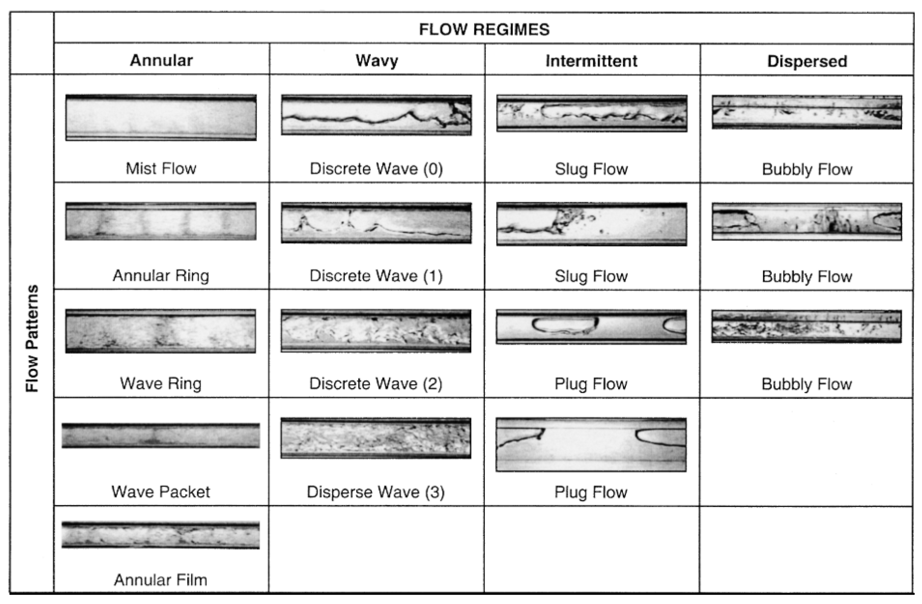
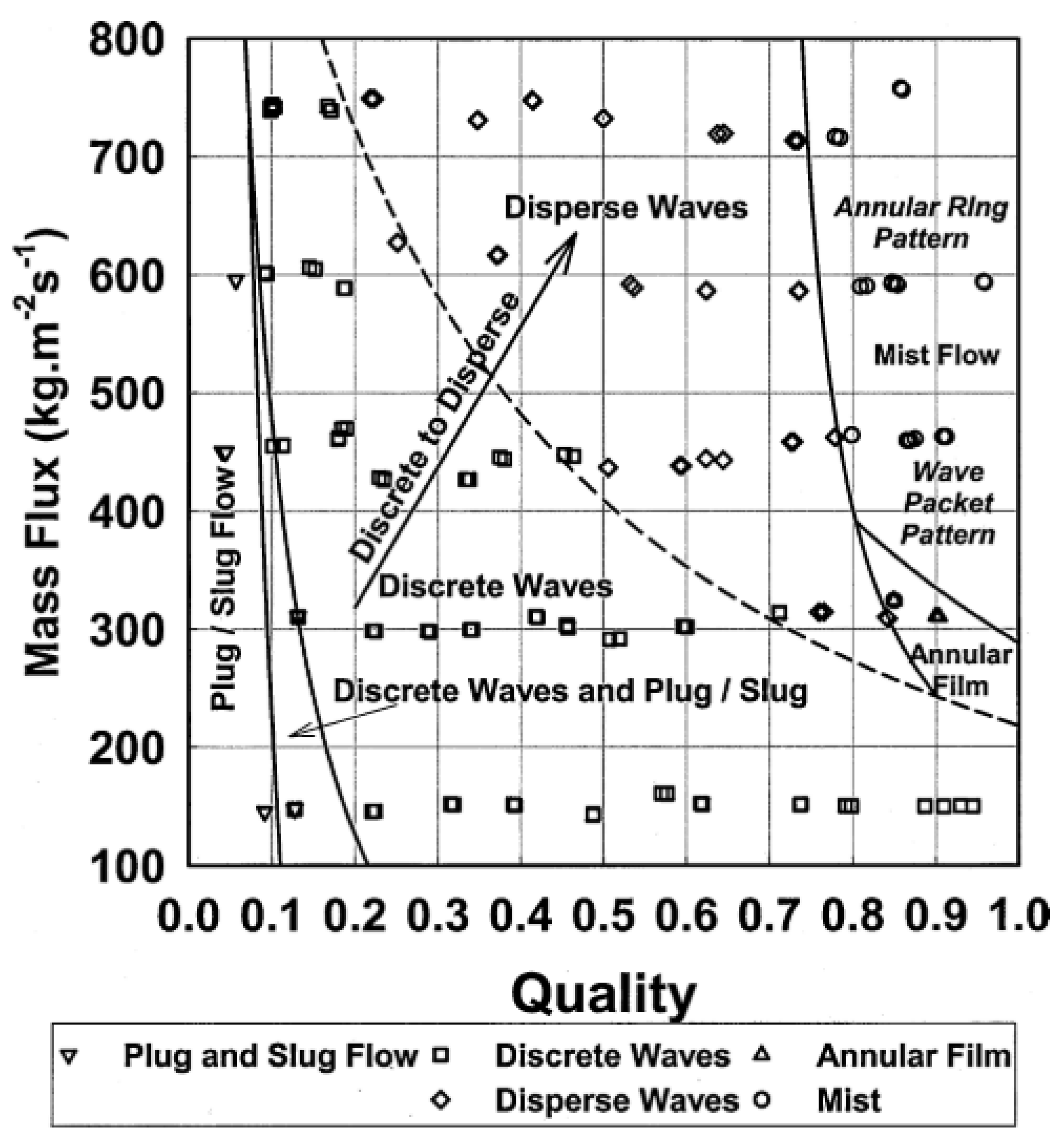
2.2. Condensation Flow Regimes Inside Micro/Minichannels

Microchannels exhibit distinct flow behaviours compared to conventional-sized channels. In microchannels, while inertial and viscous effects become more dominant, the effect of buoyancy force diminishes. Experimental investigations illustrating these phenomena are reported in the literature. Flow pattern maps, generated through visualisation studies under varying flow conditions, serve as a foundation for physically modelling heat transfer, pressure loss, and void fraction, facilitating the comprehension of two-phase flow dynamics. The majority of visualisation and flow pattern mapping research for microchannels has focused on adiabatic flows employing air-water mixtures. However, in condensation flows, the fluid undergoes a phase change from vapour to liquid within the microchannel. Consequently, the fluid flow within a range of vapour qualities creates different flow patterns throughout the condenser. While studies on visualisation and flow mapping for microchannel condensate flow remain limited, some investigations exist in the literature.
Coleman and Garimella’s work [28] stands out among the mentioned studies for its comprehensive examination of condensation flow dynamics in small-diameter channels. Notably, they shifted the focus from adiabatic flow to condensation flow, offering insights into flow visualisation during the condensation process. Their investigation encompassed a range of parameters commonly encountered in practical applications, including temperatures, mass fluxes, and vapour quality values. Visualising the condensation flow of R134a in microchannels with circular, square, and rectangular cross-sections, they explored hydraulic diameters ranging from 1 to 4.91 mm, covering vapour qualities from 0 to 1 and mass flux between 150–750 kg/m2s. Their findings delineated four primary flow regimes—intermittent flow, wavy flow, annular flow, and dispersed flow—further classified into sub-regimes, as illustrated in Figure 1. Most condensers are typically designed for operation within the annular flow regime. Within this regime, a thin layer of liquid film forms along the channel wall, propelled by the shear stress exerted by the vapour phase at the center. As the hydraulic diameter of the channel decreases at a constant mass flux, the velocity of the vapour phase in the center increases, thereby augmenting the shear stress exerted by the vapour phase and leading to a thinner liquid film layer. Within the annular regime, a central vapour core is encased by a thin liquid film adhering to the channel walls, giving rise to various flow patterns, including mist, annular ring, wave ring, wave packet, and annular film. The mist annular pattern is characterised by an exceedingly thin liquid film, while annular rings may intermittently manifest as periodic liquid formations within the mist flow. Similarly, wave rings, characterised by a thicker liquid film, often transition into individual wave pockets, predominantly situated at the channel’s bottom side. Lastly, a uniform annular film flow pattern forms consistently along the channel’s inner perimeter. Conversely, as vapour condenses into liquid along the channel, the increase in liquid film thickness can disrupt the annular flow regime. It is also worth noting that mist, annular ring, wave ring, wave packet, and annular film regimes, which are the sub-flow forms of the annular flow regime, are affected by the changing effects of gravity and shear forces due to the change in mass flux and vapour quality [28,29]. In contrast to adiabatic flows, where microchannels typically employ air-water mixtures as working fluids, condensation flow entails the formation of a thin liquid film layer along the channel wall for various combinations of mass flux and vapour quality. The wavy flow regime depicted in Figure 1 can be observed when the influence of gravity is significant. In flows where the gravity effect becomes important, noticeable disparities in the film layers occur at the top and bottom of the channel, resulting in the formation of a wavy interface between the vapour and liquid phases. Moreover, asymmetric flow, also referred to as stratified flow, occurs when gravity predominates, leading to the accumulation of liquid at the bottom of the channel. In this flow regime, waves form at the interface due to shear stress between the two phases (vapour and liquid), which move at varying velocities. This regime is further categorised into discrete and dispersed waves. Discrete waves traverse the phase interface in larger structures, while dispersed waves exhibit a broader range of amplitudes and wavelengths [28,29]. In the intermittent flow regime, the flow of both liquid and vapour phases experiences discontinuities, leading to intermittent behaviour between the phases. Typically occurring at low mass fluxes and vapour qualities, this regime can be realised as long bubble plugs or slug flow. Within this regime, a thin liquid film layer separates the vapour phase and vapour bubbles. While the vapour bubble remains mostly uniform, instability may arise at its tip (plug). With an increase in vapour quality, a slug flow pattern emerges, characterised by an elongated vapour bubble that breaks up the liquid ahead, generating smaller bubbles [30]. Dispersed flow represents a regime where small vapour bubbles are scattered within a turbulent liquid phase, typically occurring at high mass fluxes. It can be seen as a bubbly flow pattern or a dispersed bubbly flow pattern. Bubbly flow arises when the vapour phase exhibits laminar behaviour. However, due to the turbulent nature of the liquid, the bubbles lack uniformity in shape and are smaller compared to those in the plug flow pattern of the intermittent flow regime. As the mass flux of the vapour phase increases, the number of bubbles decreases, dispersing within the liquid flow [30].
Flow pattern maps are typically generated by plotting two flow parameters on a coordinate system. One common representation is in terms of mass flux and vapour quality. This format suits operations within a fixed-diameter channel for a specific fluid. Coleman and Garimella [28] developed a flow pattern map, depicted in Figure 2 [28,29], based on the flow regimes outlined in Figure 1. According to Figure 2, for a circular cross-section pipe with a diameter of 4.91 mm, the wavy flow regime dominates the majority of the mass flux-vapour quality coordinates. However, a small region shows the coexistence of plug, slug, and discrete wave regimes. Furthermore, it is evident that as mass flux and vapour quality increase, the waves become more dispersed.
Flow regimes directly influence parameters such as heat transfer coefficient and pressure drop in the channel. Figure 3 depicts a typical flow pattern transition and the associated distributions of the two-phase heat transfer coefficient and frictional pressure drop during condensation inside small-diameter horizontal channels [31,32]. As shown in Figure 3, the fluid enters the channel as vapour and gradually transitions to the liquid phase along the wall under the influence of heat flux applied to the channel walls. The annular flow regime initiates with the formation of an extremely thin liquid film layer along the flow direction of the channel. In this region, the liquid film layer is exceptionally thin, resulting in minimal heat conduction resistance exerted by the liquid. Consequently, according to Figure 3a, a high heat transfer coefficient is achieved within the channel in this region. As condensation progresses, the liquid film layer thickens, leading to a decrease in vapour quality and, consequently, a reduction in the condensation heat transfer coefficient. The gradual thickening of the liquid film due to condensation along the channel results in the formation of slug and bubbly flow regimes, respectively. Ultimately, the vapour completely condenses into the liquid phase [31]. The condensation heat transfer coefficient gradually decreases depending on the influence of these flow regimes. In compliance with Figure 3b, condensation commences with the formation of a thin liquid film along the channel walls within the annular flow regime. An increase in liquid flow rate results in the axial thickening of the film. Velocity differentials between the vapour core and the annular liquid film induce instabilities along the interface of the film. Depending on operational parameters, the initially laminar flow near the film initiation region may transition to turbulent. The presence of interfacial waviness amplifies the interfacial shear stress exerted by the vapour core on the film, thereby elevating the pressure gradient. As the film thickens further downstream, the peaks of the prominent waves begin to merge, bridging liquid films across the channel and leading to a transition to the slug flow regime. Continued condensation diminishes the length of the elongated bubbles, ultimately causing them to fragment into smaller bubbles with diameters significantly smaller than those of the channel within the bubbly flow regime. Eventually, the entire flow transforms into a single-phase liquid. It is noteworthy that condensation is accompanied by an axial slowdown of the flow, and the decreasing velocity disparity between the two phases results in a reduction in interfacial shear stress and a corresponding decrease in the pressure gradient [32].

2.3. Void Fraction Models

In two-phase flows, the void fraction stands as a crucial parameter for calculating heat transfer coefficients and pressure drops [33]. Understanding the void fraction provides insights into the fluid dynamics of the two-phase flow. For instance, computing the void fraction in the annular flow regime aids in estimating the thickness of the condensed liquid film. Moreover, the void fraction facilitates determining the required fluid volume for closed systems such as the refrigeration cycle. Essentially, the void fraction is defined as the ratio of the cross-sectional area occupied by the vapour ( A c , v ) to the total cross-sectional area of the channel ( A c ), expressed as
= A c , v A c
Determining this parameter is a critical step that offers an approximation to the equations required for predicting pressure drop and heat transfer in two-phase flow [33]. It is essential not to confuse vapour quality with void fraction. The vapour quality x is a thermodynamic parameter dictated by the state of the two-phase mixture, whereas the void fraction relies on flow properties and has been scrutinised in various studies. Unlike investigations into flow regimes mentioned earlier, the majority of void fraction inquiries have centered on larger tubes with adiabatic air-water flows. Research on void fraction in microchannels is comparatively scarce, with limited data available on void fraction during condensation [33]. Although not developed for condensation flow in micro/minichannels, existing void fraction prediction models can be used for micro/minichannel condensation flows, as presented in Table 4.
Koyama et al. [40] employed rapid closing valves to measure void fractions of R134a condensation within 7.52 mm smooth tubes and 8.86 mm internal diameter micro-finned tubes, operating across pressures spanning from 800 to 1200 kPa and mass fluxes ranging from 90 to 250 kg/m2s. Their findings indicated that the correlations by Smith [41] and Baroczy [36] matched their experimental data. Meanwhile, Jassim et al. [42] demonstrated that incorporating correlations from existing literature [37,43] into their proposed flow regime map effectively captured a comprehensive database of void fraction measurements, encompassing various methodologies across condensing, adiabatic, and evapourating flows.
Winkler et al. [38] conducted void fraction measurements tailored to specific flow regimes within round, square, and rectangular channels, featuring hydraulic diameters spanning 2 to 4.91 mm for R134a at 1400 kPa, employing video image analysis. Their study proposes novel drift-flux void fraction models specifically designed for wavy and intermittent regimes. They observed negligible influence of mass flux or diameter in the wavy regime, although some diameter effects were noted in the intermittent regime.
Building upon the study of Winkler et al. [38], Keinath and Garimella [44] expanded the analysis to encompass high-speed video documentation of flow regimes and void fractions during the condensation of R-404A within tubes ranging from 0.508 to 3.00 mm in internal diameter. Operating at reduced pressures from 0.38 to 0.77 and mass fluxes spanning 200 to 800 kg/m2s, their approach involved recording high-speed videos oriented primarily along the horizontal axis along the side face, supplemented by top-down recordings for cross-validation. This setup facilitated three-dimensional reconstruction, akin to the method of Triplett et al. [45], allowing void fraction measurements across various flow regimes, including intermittent, bubbly/annular, and wavy flows. Additionally, their expanded dataset enabled the extraction of additional parameters such as slug frequencies, vapour bubble velocity, vapour bubble dimensions, and liquid film thicknesses, offering comprehensive insights into the multiphase flow dynamics. Keinath and Garimella [44] compared three different void fraction models in their study for modelling microchannel condensate flow. As a result of this comparison, they determined that the most compatible model with the data obtained from the study was the Baroczy [36] model. For this reason, the Baroczy [36] model for microchannel condensate flows is one step ahead of other void fraction models.
Milkie et al. [46] emphasised the impact of diameter on the distribution of α across the channel cross-section. They noted that for d = 15 mm and G = 150 kg/m2s, nearly all of the liquid accumulates in the condensate layer along the entire range of x, particularly evident in wavy flow patterns. Conversely, under similar conditions, the percentage of liquid confined to the condensate layer fluctuates from 6% at x = 0.86 to 91% at x = 0.13 for d = 7 mm. Consequently, in larger diameters, gravitational effects predominate over surface tension and inertia throughout the vapour quality range, effectively retaining the liquid predominantly within the condensate layer situated at the bottom of the tube. Furthermore, Milkie et al. [46] compared their void fraction measurements against several prediction methods, including the homogeneous model, Baroczy [36], Premoli et al. [47], Rouhani and Axelsson [48], El Hajal et al. [39], Jassim et al. [42], and their own proposed method [46]. Generally, these prediction methods exhibited reasonable agreement with the experimental data of Milkie et al. [46], with some exceptions. The homogeneous model tended to overpredict the experimental data, particularly at low void fractions, while the Baroczy [36] method showed underpredictions. El Hajal et al. [39] method provided reasonable predictions, but failed to capture the increasing trend of void fraction with rising mass flux. The methods that yielded the most accurate predictions according to Milkie et al. [46], were their own proposed method [46] and the one by Jassim et al. [42], which combines El Hajal et al. [39] correlations for annular flow and Graham [49] for wavy flow. It is important to note that the Milkie et al. [46] method was fine-tuned based on their own dataset, hence its superior performance with their data.

3. Condensation Flow of Refrigerants Inside Mini/Micro-Channels

The decrease in hydraulic diameter during condensation leads to different flow regimes and heat transfer mechanisms in the microchannel compared to conventional channels [3]. Therefore, understanding the fluid flow and heat transfer properties during the condensation of the refrigerant in the microchannel becomes important for condenser design. Experimental studies on a wide range of subjects, such as various working fluids, mini/micro geometries, and operating conditions, shed light on subsequent predictive modelling studies. Numerical simulations can be a useful tool to understand condensation in microchannels, especially in cases where specific experimental data or correlations are not available. There are some Computational Fluid Dynamics (CFD) simulations in the literature that focus on the thermal characteristics of condensation inside the microchannel. In this context, researchers have focused on both experimental and numerical investigations, and flow visualisation studies to better understand the condensation heat transfer and pressure drop mechanisms in microchannel geometries.

3.1. Experimental Studies Focused on Mini/Microchannel Condensation of Refrigerants

Early experimental investigations of two-phase flow in mini/microchannels typically employed adiabatic conditions, where the liquid-vapour mixture is emulated using a liquid-gas combination to simplify the process. Adiabatic studies were conducted to elucidate fundamental flow characteristics at the micro- and mini-scale, involving the observation and mapping of flow regimes and the assessment of associated frictional pressure drop across the microchannel. However, there has been a notable increase in recent experiments focusing on condensing flows under non-adiabatic conditions in small-diameter channels compared to adiabatic two-phase flows [50]. These studies aim to examine the influence of various factors, such as operating conditions, channel geometry, surface characteristics, enhanced surface structures, and refrigerant type, on condensation flow regimes, heat transfer coefficients, and pressure drop, as discussed in this section.
Garimella [29] provided a comprehensive overview of flow visualisation techniques applied in micro- and minichannel configurations to develop models for pressure drop and heat transfer during refrigerant condensation. Investigating condensation flow mechanisms across round, square, and rectangular tubes with hydraulic diameters ranging from 1 to 5 mm and under various saturation temperatures, vapour qualities, and mass fluxes (ranging from 150 to 750 kg/m2s), the study employed flow visualisations to analyse the effects of channel geometry and miniaturisation on flow regime transitions. The author categorised the observed flow mechanisms into four distinct regimes. Similarly, Mederic et al. [51] carried out an experimental study of complete condensation flow in a minichannel, which was undertaken for a range of mass flux between 3.4 and 13.8 kg/m2s. The purpose of the study is heat transfer analysis according to flow structures revealed during condensation inside a minichannel. They observed two flow regimes (with and without bubbles) in their visualisation study and proposed a critical value of the mass flow rate for the transition between these two regimes. The authors concluded that the impact of the existence of a bubbly zone is underscored by its effects on heat transfer and pressure drops. After that, Mederic et al. [52] conducted experimental research, presenting visual data on condensing flow patterns in three tubes with inner diameters of 10, 1.1, and 0.56 mm. Based on the visualisation data, they classified the condensation flow into three zones.
Additionally, Zhang et al. [53] conducted experimental investigations on condensation heat transfer and pressure drop of R22, R410A, and R407C in two single-round microchannels. The study measured condensation heat transfer coefficients and two-phase pressure drop across saturation temperatures of 30 and 40 °C, with mass fluxes ranging from 300 to 600 kg/m2s and vapour qualities between 0.1 and 0.9. El Achkar [54] conducted an examination of flow patterns and heat transfer dynamics during the condensation process of n-pentane in an air-cooled micro-condenser with a square cross-section. Their experimental setup comprised a borosilicate square microchannel, featuring inner and outer edges measuring 553 mm and 675 mm, respectively, and a length of 208 mm. The study aimed to establish a correlation between flow patterns and heat transfer characteristics. Liu et al. [55] conducted experimental investigations into the heat transfer characteristics of R32, R152a, and R22 during condensation in circular (Dh = 1.152 mm) and two square channels (Dh = 0.952 and 1.304 mm). The experiments encompassed saturation temperatures ranging from 30 to 50 °C, mass fluxes from 200 to 800 kg/m2s, and vapour qualities from 0.1 to 0.9. They explored the impact of flow conditions (mass flux, vapour quality, saturation temperature, and coolant inlet temperature), channel diameter, channel geometry, and thermophysical properties on the heat transfer coefficients. Furthermore, Liu et al. [56] carried out an experimental study on the pressure drop characteristics of R32, R152a, and R22 during condensation under the same experimental conditions. Their findings revealed that pressure drops increase with rising mass flux and vapour quality and decreasing saturation temperature and channel diameter. However, frictional pressure drops exhibited insensitivity to coolant conditions. In a separate investigation, Liu et al. [57] presented empirical data on heat transfer and pressure drop for the condensation of propane, R1234ze (E), and R22 in both circular (with Dh = 1.085 mm) and square (with Dh = 0.952 mm) horizontal microchannels. Their experiments, conducted at saturation temperatures of 40 and 50 °C, encompassed a range of mass fluxes from 200 to 800 kg/m2s and vapour qualities from 0.1 to 0.9. This study sought to explore the influences of mass flux, vapour quality, saturation temperature, and channel geometry on heat transfer coefficients and pressure drops. Furthermore, Al-Zaidi et al. [58] conducted an experimental investigation to analyse the impact of refrigerant mass flux, local vapour quality, coolant flow rate, and inlet coolant temperature on local condensation heat transfer coefficients. Their study employed rectangular multi-microchannels with a hydraulic diameter of 0.57 mm, utilising HFE-7100 as the refrigerant. Flow visualisation techniques were also employed to capture the flow patterns during the condensing process. The recent experiments investigating the condensation of refrigerants in mini- and microchannels are summarised in Table 5.

3.2. Numerical Studies Focused on Mini/Microchannel Condensation of Refrigerants

Numerical simulations offer a valuable avenue for comprehending microchannel condensation in the absence of dedicated experimental data or correlations. In an effort to mitigate experimental costs and efforts, there is a growing emphasis on developing numerical models that are independent of particular geometries and fluid properties. Existing literature features several numerical investigations concentrated on elucidating the fluid flow and heat transfer mechanisms associated with refrigerant condensation within mini/microchannels. In numerical simulation studies of condensation flow in microgeometries, researchers first addressed the dynamics of liquid film formation and the behaviour of the flow regimes that occur during condensation. Following this, in light of experimental findings, simulation studies have begun to be carried out on the effects of parameters such as steam quality, mass flux, and hydraulic diameter on the flow regime and heat transfer mechanisms in order to clarify local flow phenomena.
Wu and Li [59] proposed a transient numerical investigation for analysing condensation heat transfer and flow characteristics. Their research delved into simulating the condensation flow of R32 within a circular tube of 0.1 mm diameter. They systematically investigated four distinct flow patterns (annular, injection flow, slug flow, and bubbly flow) within a two-dimensional computational domain. Da Riva and Del Col [60] conducted simulations of R134a condensation within a circular minichannel with a 1 mm inner diameter, considering both high (G = 800 kg/m2s) and low (G = 100 kg/m2s) mass fluxes. Their study incorporated the influences of interfacial shear stress, gravity, and surface tension on horizontal tube orientation. Subsequently, they extended their simulations to vertical downflow under normal gravity conditions and also performed simulations to assess non-gravity effects. Similarly, in their work, Da Riva and Del Col [61] developed a numerical model to simulate laminar liquid film condensation in a horizontal circular minichannel with a 1 mm internal diameter. Utilising the volume of fluid (VOF) method, they conducted three-dimensional simulations of R134a fluid film condensation within the minichannel, exploring the impact of surface tension by comparing simulations with and without its consideration under their specified conditions. Ganapathy et al. [62] introduced a numerical model based on the VOF method to simulate fluid flow and heat transfer during condensation within a single microchannel. They conducted transient two-dimensional simulations for the condensation of R134a in a microchannel with a diameter of 100 µm. Their simulations encompassed a range of vapour mass fluxes at the channel inlet, varying from 245 to 615 kg/m2s, and heat fluxes spanning 200 to 800 kW/m2. Chen et al. [63] conducted a numerical simulation based on the VOF method. Their study focused on simulating the condensation flow of refrigerant FC-72 within a rectangular microchannel with a hydraulic diameter of 1 mm. Turbulence effects were simulated using the realisable k−ε model. Their simulations revealed that reducing the wall cooling heat flux or increasing the mass flux of the flow led to an increase in the length of the vapour column. Bortolin et al. [64] conducted steady-state numerical simulations to investigate the condensation of R134a within a 1 mm square minichannel. Their simulations used the VOF approach to track the vapour-liquid interface during mini/microchannel condensation. Operating at mass fluxes varied from 400 to 800 kg/m2s, the simulations maintained a uniform wall temperature as the boundary condition. Both the vapour core and liquid film were modelled as turbulent phases using a low-Reynolds number version of the SST k−ω model. The findings suggested that gravity had minimal influence in the square minichannel, with heat transfer primarily governed by shear stress and surface tension under the considered mass flux conditions. Tonelli et al. [65] conducted steady-state numerical simulations to analyse R134a condensation within horizontal channels. They explored the impact of hydraulic diameters ranging between 1 and 3.4 mm on two-phase fluid flow and heat transfer. Subsequently, the authors carried out two-dimensional transient simulations to assess the influence of wave phenomena on the condensation flow. Employing the VOF method at a saturation temperature of 40 °C and various mass fluxes (50–200 kg/m2s), these simulations provided insights into the heat transfer coefficient trends. As for their study, the steady-state simulations indicated an increase in heat transfer coefficient with decreasing channel diameter from 3.4 to 1 mm, with surface tension exhibiting negligible effects on the liquid film distribution in the 3.4 mm channel. Zhang et al. [66] conducted a numerical exploration of the heat transfer and pressure drop behaviours during the condensation of R410A within horizontal microchannel tubes (with hydraulic diameters of 0.25, 1, and 2 mm). The various saturation temperatures were considered in their study. The author’s main emphasis was on understanding how the saturation temperature of R410A influenced these characteristics. Employing the volume of fluid (VOF) model, they utilised the SST-k-ω turbulent model to simulate both vapour and liquid phases. A steady-state numerical simulation of the condensation flow of R600a was conducted by Basaran et al. [7]. The authors numerically investigated the heat transfer characteristic condensation flow at mass fluxes ranging from 200 to 600 kg/m2s inside a single circular microchannel with varying diameters. The VOF model was employed to simulate a two-phase flow, with phase change occurring at the saturation temperature, as represented by the Lee model [67]. Basaran et al. [6] also conducted a further study on the condensation flow of R600a simulations inside the microchannel. In their study, they investigated fluid flow as well as heat transfer characteristics. They made a numerical investigation to analyse the effects of mass flux, hydraulic diameter, and vapour quality on both heat transfer rate and pressure drop. To achieve this, steady-state numerical simulations were conducted to study the condensation flow of R600a within a single circular microchannel with varying diameters (0.2–0.6 mm), spanning mass fluxes from 200 to 600 kg/m2s. The authors utilised the VOF model to simulate multi-phase flow during steady-state condensation in their simulations. Validation was conducted by comparing the model results with experimental and visual data from existing literature. For analysing the flow regime, a Reynolds Averaged Numerical Simulation (RANS) approach employing the Shear Stress Transport (SST) k-ω model by Menter [68] was utilised. They proposed a new heat transfer coefficient and pressure drop correlations based on their validated simulation model for R600a microchannel condensation flow. The key studies on the condensation of refrigerants in mini- and microchannels are summarised in Table 6.

3.3. Predictive Models for Condensation Flow of Refrigerants Inside Mini/Microchannel

In the majority of studies on condensation flow at the micro/mini-scale, R134a has been used as a working fluid. In the literature, many predictive correlations have been developed based on experimental studies for R134a condensation inside micro/minichannels. These studies have mainly focused on condensation mechanisms in single [69] and multiple rectangular cross-section microchannels [1,69,70,71,72,73] and in single [69,74,75] and multiple microchannels with circular cross-section [73,76,77,78]. Similarly, predictive empirical correlations are available in the literature for other pure R11 [79], R12 [70,80], R22 [74,75,80], R32 [69,74,80], R123 [79,80], R125 [74], R236ea [72,74,81], R236fa [73,80], R245fa [69,80]. Experimental correlations have been produced for various microchannel geometries, hydraulic diameters, mass fluxes, and condensing temperatures for these refrigerants. Additionally, experimental studies have been conducted on the micro/mini-scale condensation mechanisms of R1234ze [73,80] and R1234yf [69], which are from the HydroFluoroOlefin (HFO) refrigerant family that has been produced and used in recent years. Experimental correlations regarding the condensation flow in microchannels of refrigerant mixtures such as R404A [80,82] and R410A [72,74,75,81,83], which are widely used in the refrigeration industry along with pure refrigerants, are also available in the literature. Although a large number of correlations exist to predict two-phase heat transfer in microchannel flows, most of these correlations can be verified for relatively small numbers of working fluids and narrow ranges of geometric and flow parameters [31].

3.3.1. Heat Transfer Coefficient Correlations

Experimental determination of the heat transfer coefficient in small-sized channels such as microchannels brings it along with some difficulties. In particular, limited space for the placement of measurement probes, small mass flux in the microchannel corresponding to low heat transfer rates, and high heat transfer coefficients causing small temperature differences make it difficult to measure experimental data accurately [33]. For this reason, it is useful to employ condensation predictive models that form the basis of condensation flow models in microchannels. The predictive empirical correlations developed for the condensation flow of refrigerants inside small-scale channels provided in this section.
The most important of these classical correlations is the model developed by Dobson and Chato [84], which depends on the flow regime. This correlation is based on the flow regime and comprises only stratified, wavy, and annular flow regimes. According to the correlation between Dobson and Chato [84], the heat transfer coefficient of two-phase flows corresponding to annular flow, which is controlled by shear stress, is the product of the heat transfer coefficient of the liquid calculated as a single phase with the Dittus-Boelter [85] model with a two-phase multiplier. Empirical constants and exponents of the Dobson and Chato [84] correlation are adjusted based on experiments for R134a, R22, R32, and R125 fluids with mass velocities between 25 and 800 kg/m2s, saturation temperatures of 35 to 45 °C, and heat fluxes of 5 to 15 kW/m2. According to the Dobson and Chato [84] model, when the Soliman Froude ( F r S o ) number is greater than 20 ( F r S o > 20), the flow is considered an annular flow regime. Otherwise, the flow is considered to be in the stratified wavy flow regime. The Soliman Froude ( F r S o ) number can be computed as follows:
F r S o = 0.025 R e l 1.59 1 + 1.09 X t t 0.039 X t t 1 G a 0.5 ,     R e l 1250 1.26 R e l 1.04 1 + 1.09 X t t 0.039 X t t 1 G a 0.5 ,     R e l > 1250
where X t t and G a stand for the modified Martinelli parameter and Galileo number, respectively. Dobson and Chato [84] suggest using the void fraction model of Zivi [35] in calculating the Galileo number ( G a ). The modified Martinelli parameter and Galileo number are indicated in Equations (15) and (16):
G a = g ρ l ( ρ l ρ v ) D h 3 μ l 2
X t t = ρ v ρ l 0.5 μ l μ v 0.1 1 x x 0.9
where subscript l and v stand for “liquid” and “vapour”, respectively. According to the heat transfer coefficient model of Dobson and Chato [84], when the regime of the flow is annular (where the gravity effect may be neglected and the shear stress force is dominant), the Nusselt number is as in Equation (17):
N u a n n u l a r = 0.023 R e l 0.8 P r l 0.4 1 + 2.22 X t t 0.89
Moser et al. [86] proposed an analytical model on condensation in the annular flow regime, which is a shear stress-controlled flow regime, in circular cross-section tubes with hydraulic diameters between 3.14 and 20 mm. They conducted their experiments on seven different types of halocarbon refrigerants in the mass flux range of 87 to 862 kg/m2s and at temperatures between 22 and 52 °C. Their model is based on an equivalent Reynolds number ( R e e q ), which requires prediction methods for the single-phase heat transfer coefficient and the two-phase frictional pressure gradient:
R e e q = l o 8 7 R e l o
To compute the R e e q , the friction coefficient of each phase, it is required separately. The friction coefficients of the phases can be calculated with the following expressions:
l o 2 = A 1 + 3.24 A 2 F r T P 0.045 W e T P 0.035
A 1 = ( 1 x ) 2 + x 2 ρ l ρ v f v o f l o
A 2 = x 0.78 ( 1 x ) 0.24 ρ l ρ v 0.91 μ v μ l 0.19 1 μ v μ l 0.7
F r T P = G 2 g D h ρ T P 2
W e T P = G 2 D h ρ T P σ
ρ T P = 1 ρ b + 1 x ρ s 1
where F r T P and W e T P are Froude and Weber numbers for two-phase condensation flow, respectively. Also, subscripts l o is liquid-only”, subscripts v o is “vapour-only”, and T P is “two-phase”. According to the Moser et al. [86] model, the Nusselt number can be calculated as given in Equation (25):
N u = 0.0994 0.126 × P r l 0.448 R e l 0.113 × P r l 0.563 R e e q 1 + 0.11025 × P r l 0.448 P r l 0.815 1.58 × ln R e e q 3.28 2.58 × ln R e e q + 13.7 P r l 2 / 3 19.1
Koyama et al. [40] discussed the condensation of R134a in two different extruded aluminium multi-port microchannel tubes and proposed a heat transfer model. One of the tubes they used in their experimental setup had eight microchannels (ports) with a hydraulic diameter of 1.11 mm; the other tube contained nineteen microchannels with a hydraulic diameter of 0.8 mm. They carried out their tests in the mass flux range of 100 to 700 kg/m2s at 60 °C. The model proposed by Koyama et al. [40] consists of the asymptotic sum of terms related to forced convection condensation ( F ) and gravity-controlled ( B ) condensation.
N u = ( N u F 2 + N u B 2 ) 1 / 2
where N u F is the forced convection condensation term and N u B is the gravity-controlled (buoyancy) condensation term. N u F can be computed as follows:
N u F = 0.0152 ( 1 + 0.6 P r l 0.8 ) v X t t R e l 0.77
v 2 = 1 + 21 1 e 0.319 D h X t t + X t t 2
R e l = G D h ( 1 x ) μ l
where X t t is the modified Martinelli parameter (Equation (16)). Gravity controlled condensation term ( N u B ) is expressed as in Equation (30):
N u B = 0.725 H ( ξ ) G a P r l P h 1 / 4
H ξ = ξ + 10 1 ξ 0.1 1 + 1.7 × 10 4 R e l o ξ ( 1 ξ )
P h = C p l ( T s a t T w a l l , i ) h f g
where T s a t is the saturation temperature, T w a l l , i is the inner wall temperature of the tube, and h f g is the vaporisation enthalpy. At the same time, ξ represents the void fraction in the Koyama et al. [40] model, and it is written as in Equation (33).
ξ = 1 + ρ v ρ l 1 x x 0.4 + 0.6 ρ l ρ v + 0.4 1 x x 1 + 0.4 1 x x 1
Bandhauer et al. [77] and Agarwal et al. [87] experimentally examined the condensation of R134a in circular microchannels with hydraulic diameters ranging from 0.506 to 1.524 mm and non-circular microchannels with hydraulic diameters ranging from 0.424 to 0.839 mm. They presented a new heat transfer coefficient model with the data obtained from their experiments between 150 and 750 kg/m2s. Bandhauer et al. [77] stated that applying the existing shear stress-controlled heat transfer models designed for large, scaled channels to microchannels leads to poor predictions and is inadequate for microchannels. Therefore, they based their models on boundary layer analyses. Assuming that all heat is transferred within the liquid film, the following expression is given for the heat transfer coefficient at the interface at saturation temperature:
h = q ( T s a t T w a l l ) = ρ l C p l u T +
q = ( k + ρ × ε h × C p ) d T d y
τ = ( μ + ρ × ε m ) d u d y
where T + denotes the dimensionless turbulence temperature, and it can be expressed as follows:
T + = ρ l C p l u q   ( T i T w a l l )
where u is defined as the friction velocity. Bandhauer et al. [77] and Agarwal et al. [87] defined the friction velocity according to the interface shear stress instead of the commonly used wall shear stress. In this respect, the friction velocity ( u ) is given in Equation (38).
u = τ i ρ l  
τ i = P L D h 4
Based on the approach proposed by Bandhauer et al. [77] and Agarwal et al. [87], the heat flux defined in Equation (35) needs the dimensionless temperature gradient. The dimensionless temperature gradient is provided in Equation (40).
d T + d y + = 1 P r l + ρ l × ε h μ l 1
In order to integrate this expression, the liquid film thickness can be directly calculated with the void fraction model of Baroczy [36] as follows:
δ f i l m = ( 1 ) D h 2  
The film thickness provided in Equation (41) is used to obtain dimensionless film thickness:
δ f i l m + = δ f i l m × ρ l × u μ l  
Since the film thickness is small compared to the pipe radius, assuming ε h = ε m , the simplified two-zone dimensionless temperature is expressed as follows:
T + = 5 P r l + 5 ln P r l δ f i l m + 5 1 + 1 ,   for   R e l < 2100
T + = 5 P r l + 5 ln P r l + 1 + 30 δ f i l m + d y + 1 P r l 1 + y + 5 1 y + R +   for   R e l > 2100
Cavallini et al. [88] conducted an experimental study to develop a heat transfer model for microchannels. They wanted to produce a model with high accuracy and ease of application. They conducted a comparative study with refrigerants commonly used in refrigeration, air conditioning, and heat pump applications. In their experiments, they considered the condensation flow of R134a in a tube with a 3 mm hydraulic diameter. To facilitate the applicability of the model, they included only two equations in their model: ΔT-dependent and ΔT-independent. According to Cavallini et al. [88], the heat transfer coefficient for a certain fluid depends on its mass flux, vapour quality, channel geometry, and saturation temperature. However, it does not always depend on the difference between the saturation temperature and the internal wall temperature (ΔT). According to the authors, the dependence of the heat transfer coefficient on ΔT only exists in the flow regime where gravity effects dominate. Accordingly, the heat transfer coefficient of the condensation flow in microchannels, where gravity loses its effect as a flow regime, is independent of ΔT. It is worth noting here that the ΔT-independent flow regime and the ΔT-dependent flow regime, respectively, correspond to the annular and wavy stratified flow regimes. Cavallini et al. [88] also presented a transition criterion for ΔT-dependent and ΔT-independent flow regimes. According to this transition criterion, when the dimensionless gas velocity ( J G ) is greater than the dimensionless transition gas velocity ( J G T ) it is classified as microchannel condensation flow. This corresponds to ΔT-independent flow regime. When the dimensionless gas velocity ( J G ) is smaller than the dimensionless transition gas velocity ( J G T ) , condensation flow is classified as ΔT-dependent flow regime where gravity effects are dominant. J G T and J G are expressed as in Equations (45) and (46).
J G T = 7.5 4.3 X t t 1.11 + 1 3 + C T 3 1 / 3
C T = 1.6 ,     f o r   h y d r o c a r b o n s 2.6 ,     f o r   o t h e r   r e f r i g e r a n t s
J G = x G g ρ v ( ρ l ρ v ) D h
The correlation proposed by Cavallini et al. [88] is given below for ΔT-independent flow regimes ( J G >   J G T );
h A = h l o 1 + 1.128 x 0.817 ρ l ρ v 0.3685 μ v μ l 0.2363 1 μ v μ l 2.144 P r l 0.1
h l o = 0.023 R e l o 0.8 P r l 0.4 k l D h
For ΔT-dependent flow regimes ( J G <   J G T ), the heat transfer coefficient is provided in Equations (50) and (51).
h D = h A J G T J G 0.8 h S T R A T   J G J G T + h S T R A T
h S T R A T = 0.725 1 + 0.741 1 x x 0.3321 1 × k l 3 ρ l ( ρ l ρ v ) g h v l μ l D h Δ T 0.25 + ( 1 x 0.087 ) h l o
Son and Lee [89] carried out experiments to determine the heat transfer characteristics of the condensation flow of R22, R134a, and R410A in tubes with inner diameters of 1.77, 3.36, and 5.35 mm, at mass flux between 200 and 400 kg/m2s and at a saturation temperature of 40 °C. The authors proposed a new correlation as another form of the Dobson and Chato [84] model. They reported that they modified the Dobson and Chato [84] model because the model could well predict the condensation flow heat transfer characteristics of R22, R134a, and R410A at varying tube diameters. Regression analysis of the experimental data obtained by using the Dittus-Boelter [85] correlation to determine the single-phase Nusselt number gave the expression in Equation (52).
N u = 0.034 R e l 0.8 P r l 0.3 f c ( X t t )
where f c ( X t t ) is a two-phase multiplier, and it can be found by the following expression:
f c ( X t t ) = 3.28 1 X t t 0.78
Huang et al. [83] experimentally investigated the effect of oil on the condensation flow of R410A in a small-scale horizontal tube with an inner diameter of 1.6 and 4.18 mm. As a result of experiments conducted at 40 °C saturation temperature, Huang et al. [83] presented a new correlation for the heat transfer coefficient of the R410A-oil mixture. The correlation proposed by the researchers is as in Equation (54):
N u = 0.0152 ( 0.33 + 0.83 P r l 0.8 ) v X t t R e l 0.77
v = 1 + 0.5 G g ρ v ( ρ l ρ v ) D h X t t 0.35
where v is a two-phase multiplier.
Park et al. [73] experimentally compared and examined the condensation flow of the new refrigerant R1234ze with the condensation flows of R134a and R236fa. The experiments were carried out in a tube with vertically arranged rectangular microchannels with a 50–260 kg/m2s mass flux and under 25–70 °C saturation temperature conditions. They presented a modified correlation for the heat transfer coefficient according to the data they obtained as a result of their experiments. They concluded that their correlation provided a good fit for three refrigerants (R1234ze, R134a, and R236fa) over a wide range of operating conditions. Park et al. [73] model suggests Equations (56) and (57) to compute the Nusselt number.
N u = 0.0055 P r l 1.37 v X t t R e l 0.7
v = 1 + 13.17 ρ v ρ l 0.17 1 e x p 0.6 g ( ρ l ρ v ) D h 2 σ X t t + X t t 2
Bohdal et al. [82] comparatively examined the condensation flow of R134a and R404A refrigerants in tubes with 0.31–3.30 mm inner diameters. As a result of their experimental studies, they derived their own correlations for annular and annular layered flow under the conditions of mass flux 0–1300 kg/m2s, vapour quality 0–1, and saturation temperature 20–50 °C. The correlation presented by Bohdal et al. [82] is given in Equation (58).
N u = 25.084 R e l 0.258 P r l 0.495 p r 0.288 x 1 x 0.266
p r = p s a t p c r
where p r is the reduced pressure ratio and is the ratio of saturation pressure to critical pressure.
Shah [90] proposed flow regime-based extended heat transfer coefficient correlations for condensation flow in all mini/microchannel orientations. In the study, where two alternative correlations are presented, the correlations include 33 different fluids, mass fluxes between 1.1 and 1400 kg/m2s, various geometries (circular, square, quadrangular cross-sectional areas) with hydraulic diameters between 0.1 and 49 mm, and all orientations (horizontal, vertical, inclined, etc.). The author compared correlations with a comprehensive database. Shah [90] defined three different flow regimes: Regime I, which covers intermittent, annular, or mist regimes; Regime II, which covers wavy flow regimes; and Regime III, which includes stratified flow. The transition criterion between these flow regimes was determined according to the Weber number ( W e ) of the vapour phase. The Weber number is the ratio of inertial forces to the surface tension force. In this respect, the Weber number of the vapour phase ( W e v ) can be calculated as follows:
W e v = G 2 D h ρ v σ
According to the Shah [90] model, the transition from Regime I to Regime II occurs when W e v = 100 . On the other hand, Regime I is valid when W e v > 100 and J G > 0.98 ( Z + 0.263 ) 0.62 . It is worth noting here that J G is the dimensionless gas (vapour) velocity (Equation (47)) and Z is the correlation constant. The correlation constant, Z , is expressed as follows:
Z = 1 x 1 0.8 p r 0.4
where p r is the reduced pressure ratio (Equation (59)).
Regime III occurs when W e v > 20 and J G > 0.95 ( 1.254 + 2.27 × Z 1.249 ) 1 . According to these criteria, if the flow is not Regime I or Regime III, it can be defined as Regime II. Alternative correlations presented by Shah [90] are as follows:
Correlation #1
h I = h l o 1 + 3.8 Z 0.95 μ l 14 μ v ( 0.0058 + 0557 P r )
h N u = 1.32 R e l o 1 / 3 k l 3 ρ l ( ρ l ρ v ) g μ l 2 1 / 3
h l o = 0.023 R e l o 0.8 P r l 0.4 k l D h
Correlation #2
h I I = h l o 1 + 1.128 x 0.817 ρ l ρ v 0.3685 μ v μ l 0.2363 1 μ v μ l 2.144 P r l 0.1
Correlation #2 is the same as the model developed by Cavallini et al. [88] for ΔT-independent flow regimes. Heat transfer coefficients can be predicted depending on the flow regime, as shown in the following list:
If the flow is Regime I, h = h I I (Correlation #2)
If the flow is Regime II, h = h I +   h N u (Correlation #1)
If the flow is Regime III, h = h I (Correlation #1).

3.3.2. Pressure Drop Correlations

Although the studies in the literature for small tubes are mostly on nitrogen-water and air-water mixtures, in recent years, experimental studies have also been carried out on the condensation flows of refrigerants in mini/microchannels. The empirical pressure drop correlations on condensation flows of refrigerants inside microchannels are provided in this section.
Pressure drops of mini/microchannel condensation flows are generally modelled by applying a flow regime-based approach or by experimentally modifying the two-phase multipliers of classical correlations. In this way, flow phenomena occurring at the microscale can be taken into account [33]. For this reason, it would be useful to first examine the classical correlations that are the subject of the models developed for microchannels. The most well-known classical correlations are Lockhart and Martinelli [34] and Friedel [91].
The correlation of Lockhart and Martinelli [34] is given in Equation (66), and it is based on the two-phase multiplier ( l 2 ) given in Equation (67). The two-phase multiplier is basically defined as the ratio of a two-phase pressure drop to a single-phase (liquid or vapour) pressure drop.
P L = l 2 d P d z l
l 2 = 1 + C X + 1 X 2
where C is a parameter depending on the flow regime and X is the Martinelli parameter. The parameter C and Martinelli parameter X are computed as in Equations (68) and (69), respectively.
C = 20 ,     L i q u i d : T u r b u l e n t /   V a p o r : T u r b u l e n t 12 ,     L i q u i d : L a m i n a r   /   V a p o r : T u r b u l e n t 10 ,     L i q u i d : T u r b u l e n t   /   V a p o r : L a m i n a r     5 ,     L i q u i d : L a m i n a r / V a p o r : L a m i n a r
X = d P d z v d P d z l 1 / 2
On the other hand, Friedel [91] produced the following correlation based on 25,000 data points obtained for adiabatic flow in channels with a hydraulic diameter greater than 1 mm.
P L = l o 2 d P d z l o
l o 2 = E + 0.32 F H F r T P 0.045 W e T P 0.035
E = ( 1 x ) 2 + x 2 ρ l f v o ρ v f l o
F = x 0.78 ( 1 x ) 0.24
H = ρ l ρ v 0.91 μ v μ l 0.19 1 μ v μ l 0.7
where f v o and f l o are the single-phase friction factors for only vapour and only liquid, respectively.
Mishima and Hibiki [92], who studied the flow regime and void fraction with an air-water mixture in small channels with diameters of 1 to 4 mm, suggested using the C expression given in Equation (75) for small-scale channels using the correlation of Lockhart and Martinelli [34]. In this respect, the parameter C (Equation (75)) is applied to the correlation of Lockhart and Martinelli [34] and is given in Equations (66) and (67) according to the Mishima and Hibiki [92] correlation.
C = 21 ( 1 e 0.319 D )
In addition to these classical correlations, empirical correlations were derived for the condensation flow of refrigerants in microchannels. Garimella et al. [93] developed an experimental correlation based on the flow regime at mass fluxes of 150–450 kg/m2s for the condensation flow of R134a in circular cross-section channels with diameters ranging from 0.5 to 4.91 mm. Garimella et al. [93] presented a pressure drop model for annular flow condensation in microchannels, assuming an equal pressure gradient in vapour and liquid at any cross-sectional area and uniform film thickness. According to Garimella et al. [93], the pressure drop taking into account the interface friction factors of the phases is as follows:
P L = 1 2 f i ρ v G 2 x 2 ρ v 2.5 1 D h
where, , is the void fraction according to the Baroczy [36] model and f i is the interface friction factor. To compute the interface friction factor f i according to the Darcy friction factor, it is necessary to calculate the Reynolds number of each phase occupying the cross-sectional area (for the annular flow model). In this context, the Reynolds numbers of each phase occupying the cross-sectional area can be calculated as follows:
R e l , = G D ( 1 x ) 1 + μ l
R e v , = G D x μ l
The interface friction factor, f i , can be found by proportioning it to the liquid phase Darcy friction factor, f l , and can be correlated according to the Martinelli parameter, X :
f i f l = A X a R e l , b φ c
where φ denotes the surface tension factor. It is computed by using Equations (80) and (81). The friction factor ( f l and f v ) of each phase is determined by f = 64 / R e for laminar flow ( R e l , < 2100 ) and by using the Blasius expression with f = 0.316 × R e 0.25 for turbulent flow ( R e l , > 3400 ).
φ = J l μ l σ
J l = G ( 1 x ) ρ l ( 1 )
The constants in the Garimella et al. [93] correlation depend on the flow regime, and they can be computed as follows:
I f   R e l , < 2100   A = 1.308 × 10 3 a = 0.4273 b = 0.9295 c = 0.1211
I f   R e l , > 3400 A = 25.64 a = 0.532 b = 0.327 c = 0.021
Cavallini et al. [74] performed an experimental study on the condensation pressure drop of refrigerants R22, R134a, R125, R32, R236ea, R407C, and R410A in a circular tube (Dh = 8 mm). They took into consideration mass fluxes between 100 and 750 kg/m2s and saturation temperatures varied from 30 to 50 °C. Cavallini et al. [74] suggested modifying the Friedel [91] correlation for the microchannel condensation flow of refrigerants. It is worth noting here that the E parameter (Equation (72)) of the Friedel [91] correlation remains the same. The correlation proposed by Cavallini et al. [74] is given below:
P L = l o 2 d P d z l o
l o 2 = E + 1.262 F H W e 0.1458
F = x 0.6978
H = ρ l ρ v 0.3278 μ v μ l 1.181 1 μ v μ l 3.477
Bohdal et al. [82] experimentally examined the pressure drop during condensation flow of R134a, R404A refrigerants in microchannels with an inner diameter of 0.31–3.30 mm. As a result of their study, they obtained their own correlations for annular and annular layered flow under the conditions of mass flux between 0 and 1300 kg/m2s, vapour quality between 0 and 1, and saturation temperature ranging from 20 to 50 °C. The correlation derived by Bohdal et al. [82] is:
d P d z f = d P d z l o 0.003 P s a t P c r 4.722 E 0.992 + 143.74 F 0.671 H 0.019 W e 0.308
F = x 0.98 ( 1 x ) 0.24
H = ρ l ρ v 0.91 μ v μ l 0.19 1 μ v μ l 0.7
f x = 8 8 R e x + 2.457 × l n R e x 7 0.9 16 + 37,530 R e x 16 1.5 1 / 12
where the E parameter is the same with Equation (72). The subscript “x” represents the subscripts “lo” or “vo”.
Son and Oh [94] experimentally investigated the condensation flows of R22, R134a, and R410A refrigerants in a small-scale channel. They used a tube with a hydraulic diameter of 1.77 mm in their experiments. According to their experimental data, they developed a new correlation for condensation pressure drop using the superposition model. In their pressure drop model, they derived a new Chisholm factor ( C ) as a function of the two-phase Weber number ( W e T P ) and the two-phase Reynolds number ( R e T P ). The pressure drop model presented by Son and Oh [94] is as follows:
P L = l 2 d P d z l
l 2 = 1 + C X + 1 X 2
C = 2485   W e T P 0.407 R e T P 0.34
where two-phase Weber number ( W e T P ) is given in Equation (23). The two-phase Reynolds number ( R e T P ) can be written as in Equations (95) and (96).
R e T P = G D h μ T P
μ T P = 1 μ v + 1 x μ l 1
Sakamatapan and Wongwises [95] conducted an experimental study on the condensation flow of R134a in two types of multi-port microchannels: fourteen microchannels with a hydraulic diameter of 1.1 mm and eight microchannels with a hydraulic diameter of 1.2 mm. In their study, they found that the friction factor is dominant in the total pressure drop. It is observed that the friction factor increases with the increase in mass flux and vapour quality and decreases with increasing saturation temperature and channel size. Therefore, they developed a correlation to predict the friction factor of condensation flow at small scales using the equivalent Reynolds number ( R e e q ):
P L = 2 f T P R e e q 2 μ l 2 ρ l D h 3
f T P = 6977 R e e q 0.337   x 0.031 ρ l ρ v 6.510 μ v μ l 11.883
R e e q = G e q D h μ l
G e q = G 1 x x ρ l ρ v
Lopez-Belchi et al. [96] examined the two-phase pressure drop of refrigerants R1234yf, R134a, and R32 for condensation flow in a 1.16 mm inner diameter microchannel. With the obtained experimental data, they determined that mass flow, vapour quality, and thermophysical properties of the refrigerant influence pressure drop. According to their findings, they presented a new correlation model for the pressure drop of refrigerant inside mini/microchannels:
d P d z T P = l 2 d P d z l
l 2 = 1 + C X + 1 X 2
X 2 = d P / d z l d P / d z v
d P d z l = 2 f l G 2 ( 1 x ) 2 D h ρ l   and   d P d z v = 2 f v G 2 x 2 D h ρ v
f x = 16 R e x ,     R e x < 2000 0.25 1.1525 R e x + 895 × 10 5 ,     2000 R e x < 3000 1 16 l o g 150.39 R e x 0.98865 152.66 R e x 2 ,     R e x 3000
where the subscript “x” represents the subscript “v” or “l”. Lopez-Belchi et al. [96] model expresses the C parameter in accordance with their experimental data as follows:
C = 4.6468 × 10 6 P s a t P c r 5.5866 R e l 0.4387 ρ l ρ v 5.7189 X 0.4243

4. Conclusions and Suggestions for Future Work

The current review study presents an up-to-date, comprehensive review of studies on condensation in mini/microchannels. The transition from the macro to the micro/mini dimension as well as the void fraction and flow regimes of microchannel condensation flow were discussed as a basis for understanding small-scale condensation. The review includes experimental studies as well as correlation models, which are developed to predict condensation heat transfer coefficients and pressure drop. Predictive models for the condensation flow of refrigerants inside mini/microchannel were explored in detail. Moreover, numerical studies on micro/minichannel condensation were comprehensively presented. Environmental impacts of refrigerants were also discussed to encourage the usage of climate-friendly refrigerants together with micro/minichannels. Key conclusions of this study and future research needs are listed as follows:
  • HCs emerge as promising alternatives to HFCs and HCFCs for HVAC-R systems because they are harmless to the environment. However, there is a notable scarcity of studies focusing on crucial parameters essential for optimising systems employing them, such as heat transfer coefficients and pressure drop (Section 3.1 and Table 5). Experimental and numerical studies, particularly involving mixtures of HCs, are also lacking. Flow pattern and void fraction have an impact on the heat transfer coefficient. Mass flux and vapour quality during condensation flow are key phenomena in flow patterns. However, investigations into flow patterns and void fractions are notably lacking. Despite the apparent diversity in experimental conditions reported in the literature, the limited number of studies has resulted in sparse experimental conditions that lack complementarity with each other.
  • It is clear that conducting experimental studies on microchannels involves some difficulties. On the other hand, it is recommended to carry out experimental studies on the microchannel condensation flows of new refrigerants, especially those developed to be environmentally friendly. It has been concluded that the dissemination of these studies will make a significant contribution to the introduction of highly efficient, environmentally friendly, and ecological systems. This situation is compliant with sectoral needs as forced by regulations.
  • In addition to the manufacturing of microchannels and minichannels, the difficulty of experimental studies and the safety risks of environmentally friendly refrigerants emphasise the importance of numerical studies. In this context, it was concluded that validated numerical models are needed for various working fluids, geometries, and operating conditions. In particular, numerical models made with open-source CFD codes are quite limited. The spread of these studies will contribute to the emergence of new technologies.
  • Many prediction models that can be applied to micro/minichannels exist in the literature, but they are developed especially for HFCs, HCFCs, and mixtures of them. The prediction models for heat transfer coefficient were presented in Section 3.3.1, whereas pressure drop prediction models were provided in Section 3.3.2. Overall, researchers validated comparable qualitative behaviour in heat transfer coefficient and pressure drop when comparing pure and mixture HCs to HFCs and HCFCs across a range of parameters, including mass and heat flux, diameter, saturation temperature, vapour quality, etc., during condensation flow. Regarding the comparison between experimental data from the literature and prediction methods, it is concluded that reasonable agreements exist in the heat transfer coefficient of HC in micro/minichannels.
  • The numerical studies on flow in nanochannels, in addition to the microscale, may lead to enhanced nanochannel fabrication techniques.
  • In actual systems, refrigerants mostly flow together with lubricants. Conducting both experimental and numerical studies in which the working fluids are not only refrigerants but also refrigerant-lubricant blends will be important to making the correct designs.

Author Contributions

Conceptualisation, A.B. and A.C.B.; methodology, A.B. and A.C.B.; writing—original draft preparation, A.B.; writing—review and editing, A.B. and A.C.B.; supervision, A.B. and A.C.B. All authors have read and agreed to the published version of the manuscript.

Funding

This research received no external funding.

Institutional Review Board Statement

Not applicable.

Informed Consent Statement

Not applicable.

Data Availability Statement

Not applicable.

Conflicts of Interest

The authors declare no conflicts of interest.

Nomenclature

B o Bond number = g ( ρ l ρ v ) D h 2 / σ
B o c r Critical Bond number = ρ l / ( ρ l ρ v ) π / 4
C Chisholm factor
D Diameter, m
D h Hydraulic diameter, m
D v Vapour core diameter, m
E U European Union
f Friction factor
F r Froude number = G 2 / g D h ρ 2
F r s o Soliman Froude number
F r T P Two-phase mixture Froude number = G 2 / g D h ρ T P 2
F v o l Volume force due to surface tension, N m−3
g Gravity acceleration, kg-s−2
G Mass flux, kg m−2 s−1
GWPGlobal warming potential
h Enthalpy, J kg−1
h l v Latent heat, J kg−1
HCHydroCarbon
HFCHydroFluoroCarbon
H T C Heat transfer coefficient, W m−2 K−1
k l Thermal conductivity of the liquid phase, W m−1 K−1
L Tube length, m
MCHEMicrochannel heat exchanger
N u Nusselt number = h D h / k l
p Pressure, Pa
P r Prandtl number
R e e q All liquid Reynolds numbers = G e q D h / μ l
R e l Liquid Reynolds number = G D h ( 1 x ) / μ l
R e l o All liquid Reynolds numbers = G D h / μ l
R e T P Two-phase mixture Reynolds number = G D h / μ T P
R e v Vapour Reynolds number = G D h x / μ v
R e v o All vapour Reynolds numbers = G D h / μ v
S Mass source term, kg m−3 s−1
S E Energy source term, J m−3 s−1
T Temperature, °C
u Velocity, m s−1
V O F Volume of fluid
W e Weber number = G 2 D h / ρ σ
W e T P Two-phase mixture Weber number = G 2 D h / ρ T P 2 σ
x Vapour quality
X t t Lockhart–Martinelli parameter = ρ v / ρ l 0.5 μ l / μ v 0.1 ( 1 x ) / x 0.9
Greek symbols
α Volume fraction
Void fraction
β Tunable positive numerical coefficient, s−1
κ L Interface curvature
μ Dynamic viscosity, Pa s
μ T P Two-phase mixture viscosity = ( 1 / μ v ) + ( 1 x ) / μ l ) 1
ρ Density, kg m−3
ρ T P Two-phase mixture density = ( 1 / ρ v ) + ( 1 x ) / ρ l ) 1
σ Surface tension, N m−1
φ Fluid properties
λ Thermal conductivity, W m−1 K−1
Two-phase multiplier
Subscripts
c r Critical
e f f Effective
e q Equivalent
l Liquid
l o All-liquid
s a t Saturation
v Vapour
v o All-vapour

References

  1. Cavallini, A.; Del Col, D.; Doretti, L.; Matkovic, M.; Rossetto, L.; Zilio, C. Condensation Heat Transfer and Pressure Gradient inside Multiport Minichannels. Heat Transf. Eng. 2005, 26, 45–55. [Google Scholar] [CrossRef]
  2. Maqableh, A.M.; Khadrawi, A.F.; Al-Nimr, M.A.; Ammourah, S.A.; Benim, A.C. Heat Transfer Characteristics of Parallel and Counter Flow Micro-Channel Heat Exchangers with Varying Wall Resistance. Prog. Comput. Fluid Dyn. 2011, 11, 318–328. [Google Scholar] [CrossRef]
  3. Kandlikar, S.G.; Colin, S.; Peles, Y.; Garimella, S.; Pease, R.F.; Brandner, J.J.; Tuckerman, D.B. Heat Transfer in Microchannels—2012 Status and Research Needs. J. Heat Transf. 2013, 135, 091001. [Google Scholar] [CrossRef]
  4. Başaran, A.; Yurddaş, A. Thermal Modeling and Designing of Microchannel Condenser for Refrigeration Applications Operating with Isobutane (R600a). Appl. Therm. Eng. 2021, 198, 117446. [Google Scholar] [CrossRef]
  5. Greene, G.A. Advances in Heat Transfer; Hartnett, J.P., Bar-Cohen, A., Cho, Y.I., Eds.; Elsevier Inc.: Oxford, UK, 2006; ISBN 9780120200399. [Google Scholar]
  6. Basaran, A.; Benim, A.C.; Yurddas, A. Numerical Simulation of the Condensation Flow of the Isobutane (R600a) inside Microchannel. Heat Transf. Eng. 2021, 43, 337–361. [Google Scholar] [CrossRef]
  7. Basaran, A.; Benim, A.C.; Yurddas, A. Prediction of Heat and Fluid Flow in Microchannel Condensation. E3S Web Conf. 2019, 128, 01015. [Google Scholar] [CrossRef]
  8. Szczęśniak, S.; Stefaniak, Ł. Global Warming Potential of New Gaseous Refrigerants Used in Chillers in HVAC Systems. Energies 2022, 15, 5999. [Google Scholar] [CrossRef]
  9. Basaran, A.; Ozgener, L. Investigation of the Effect of Different Refrigerants on Performances of Binary Geothermal Power Plants. Energy Convers. Manag. 2013, 76, 483–498. [Google Scholar] [CrossRef]
  10. American Society of Heating, Refrigerating and Air-Conditioning Engineers. ASHRAE Handbook-Fundamentals; ASHRAE: Atlanta, GA, USA, 2009. [Google Scholar]
  11. Harby, K. Hydrocarbons and Their Mixtures as Alternatives to Environmental Unfriendly Halogenated Refrigerants: An Updated Overview. Renew. Sustain. Energy Rev. 2017, 73, 1247–1264. [Google Scholar] [CrossRef]
  12. Başaran, A.; Özgener, L. Doğaya Zararli Halokarbon Soğutkanlarin Çevresel Etkileri ve Alinan Önlemler. Mühendis Makina 2013, 54, 45–53. [Google Scholar]
  13. Başaran, A.; Yurddaş, A. Examination of the Effects of Different Environmentally Friendly Refrigerants on the Performance of a Beverage Refrigerators Çevre Dostu Farklı Soğutucu Akışkanların Ticari Bir Içecek Buzdolabı Performansına Etkilerinin Incelenmesi. In Proceedings of the International Advanced Researches & Engineering Congress-2017, Osmaniye, Turkey, 16–18 November 2017; pp. 1–11. [Google Scholar]
  14. Dongellini, M.; Natale, C.; Naldi, C.; Rossi di Schio, E.; Valdiserri, P.; Morini, G.L. Energy and Environmental Performance Comparison of Heat Pump Systems Working with Alternative Refrigerants. Appl. Sci. 2023, 13, 7238. [Google Scholar] [CrossRef]
  15. Jesus, G.; Aguiar, M.L.; Gaspar, P.D. Computational Tool to Support the Decision in the Selection of Alternative and/or Sustainable Refrigerants. Energies 2022, 15, 8497. [Google Scholar] [CrossRef]
  16. United Nations Environment Programme (UNEP) Questions and Answer; Global Mercury Assessment: Geneva, Switzerland, 2002.
  17. Xue, M.; Kojima, N.; Zhou, L.; Machimura, T.; Tokai, A. Trade-off Analysis between Global Impact Potential and Local Risk: A Case Study of Refrigerants. J. Clean. Prod. 2019, 217, 627–632. [Google Scholar] [CrossRef]
  18. Xue, M.; Kojima, N.; Machimura, T.; Tokai, A. Flow, Stock, and Impact Assessment of Refrigerants in the Japanese Household Air Conditioner Sector. Sci. Total Environ. 2017, 586, 1308–1315. [Google Scholar] [CrossRef] [PubMed]
  19. EU F-Gas Regulation 517/2014 Regulation (EU) No 517/2014 of the European Parliament and of the Council of 16 April 2014 on Fluorinated Greenhouse Gases and Repealing Regulation (EC) No 842/2006. Off. J. Eur. Union 2014, 2014, L150/195-230.
  20. Başaran, A. Experimental Investigation of R600a as a Low GWP Substitute to R134a in the Closed-Loop Two-Phase Thermosyphon of the Mini Thermoelectric Refrigerator. Appl. Therm. Eng. 2022, 211, 118501. [Google Scholar] [CrossRef]
  21. Mehendale, S.S.; Jacobi, A.M.; Ahah, R.K. Fluid Fow and Heat Transfer at Micro- and Meso-Scales with Application to Heat Exchanger Design. ASHRAE Trans. 2000, 106, 446–452. [Google Scholar]
  22. Kandlikar Satish, G.; Grande, W.J. Evolution of Microchannel Flow Passages—Thermohydraulic Performance and Fabrication Technology. In Proceedings of the ASME International Mechanical Engineering Congress & Exposition, New Orleans, LA, USA, 17–22 November 2002; pp. 1–13. [Google Scholar]
  23. Serizawa, A.; Feng, Z.; Kawara, Z. Two-Phase Flow in Microchannels. Exp. Therm. Fluid Sci. 2002, 26, 703–714. [Google Scholar] [CrossRef]
  24. Kew, P.A.; Cornwell, K. Correlations for the Prediction Heat Transfer in Small-Diameter of Boiling. Appl. Therm. Eng. 1997, 17, 705–715. [Google Scholar] [CrossRef]
  25. Li, J.M.; Wang, B.X. Size Effect on Two-Phase Regime for Condensation in Micro/Mini Tubes. Heat Transf.-Asian Res. 2003, 32, 65–71. [Google Scholar] [CrossRef]
  26. Brauner, N.; Maron, D.M. Identification of the Range of ‘Small Diameters’ Conduits, Regarding Two-Phase Flow Pattern Transitions. Int. Commun. Heat Mass Transf. 1992, 19, 29–39. [Google Scholar] [CrossRef]
  27. Nema, G.; Garimella, S.; Fronk, B.M. Flow Regime Transitions during Condensation in Microchannels. Int. J. Refrig. 2014, 40, 227–240. [Google Scholar] [CrossRef]
  28. Coleman, J.W.; Garimella, S. Two-Phase Flow Regimes in Round, Square and Rectangular Tubes during Condensation of Refrigerant R 134a. Int. J. Refrig. 2003, 26, 117–128. [Google Scholar] [CrossRef]
  29. Garimella, S. Condensation Flow Mechanisms in Microchannels: Basis for Pressure Drop and Heat Transfer Models. Heat Transf. Eng. 2004, 25, 104–116. [Google Scholar] [CrossRef]
  30. Nino, V.G.; Hrnjak, P.S.; Newell, T. Characterization of Two-Phase Flow in Microchannels; University of Illinois at Urbana-Champaign: Urbana, IL, USA, 2002. [Google Scholar]
  31. Kim, S.M.; Mudawar, I. Review of Databases and Predictive Methods for Heat Transfer in Condensing and Boiling Mini/Micro-Channel Flows. Int. J. Heat Mass Transf. 2014, 77, 627–652. [Google Scholar] [CrossRef]
  32. Kim, S.M.; Mudawar, I. Review of Databases and Predictive Methods for Pressure Drop in Adiabatic, Condensing and Boiling Mini/Micro-Channel Flows. Int. J. Heat Mass Transf. 2014, 77, 74–97. [Google Scholar] [CrossRef]
  33. Kandlikar, S.G.; Garimella, S.; Li, D.; Stephane, C.; King, M.R. Heat Transfer and Fluid Flow in Minichannels and Microchannels; Elsevier: Oxford, UK, 2005; ISBN 9780123815293. [Google Scholar]
  34. Lockhart, R.; Martinelli, R. Proposed Correlation of Data for Isothermal Two-Phase, Two-Component Flow in Pipes. Chem. Eng. Prog. 1949, 45, 39–48. [Google Scholar]
  35. Zivi, S.M. Estimation of Steady-State Steam Void-Fraction by Means of the Principle of Minimum Entropy Production. ASME J. Heat Transf. 1964, 86, 247–251. [Google Scholar] [CrossRef]
  36. Baroczy, C.J. Correlation of Liquid Fraction in Two-Phase Flow with Application to Liquid Metals. Chem. Eng. Prog. Symp. Ser. 1965, 61, 179–191. [Google Scholar]
  37. Steiner, D. Heat Transfer to Boiling Saturated Liquids. In VDI Heat Atlas. Society Process Engineering and Chemical Engineering, 1st ed.; Springer: Berlin/Heidelberg, Germany, 1993. [Google Scholar]
  38. Winkler, J.; Killion, J.; Garimella, S. Void Fractions for Condensing Refrigerant Flow in Small Channels. Part II: Void Fraction Measurement and Modeling. Int. J. Refrig. 2012, 35, 246–262. [Google Scholar] [CrossRef]
  39. El Hajal, J.; Thome, J.R.; Cavallini, A. Condensation in Horizontal Tubes, Part 1: Two-Phase Flow Pattern Map. Int. J. Heat Mass Transf. 2003, 46, 3349–3363. [Google Scholar] [CrossRef]
  40. Koyama, S.; Kuwahara, K.; Nakashita, K.; Yamamoto, K. An Experimental Study on Condensation of Refrigerant R134a in Multi-Port Extruded Tube. Int. J. Refrig. 2003, 26, 425–432. [Google Scholar] [CrossRef]
  41. Smith, S.L. Void Fractions in Two-Phase Flow: A Correlation Based upon an Equal Velocity Head Model. Proc. Inst. Mech. Eng. 1969, 184, 647–664. [Google Scholar] [CrossRef]
  42. Jassim, E.W.; Newell, T.A.; Chato, J.C. Prediction of Refrigerant Void Fraction in Horizontal Tubes Using Probabilistic Flow Regime Maps. Exp. Therm. Fluid Sci. 2008, 32, 1141–1155. [Google Scholar] [CrossRef]
  43. Yashar, D.A.; Wilson, M.J.; Kopke, H.R.; Graham, D.M.; Chato, J.C.; Newell, T.A. An Investigation of Refrigerant Void Fraction in Horizontal, Microfin Tubes. HVAC R Res. 2001, 7, 67–82. [Google Scholar] [CrossRef]
  44. Keinath, B.; Garimella, S. Measurement and Modeling of Void Fraction in High-Pressure Condensing Flows through Microchannels. Heat Transf. Eng. 2016, 37, 1172–1180. [Google Scholar] [CrossRef]
  45. Triplett, K.A.; Ghiaasiaan, S.M.; Abdel-Khalik, S.I.; Lemouel, A.; Mccord, B.N.; Woodru, G.W. Gas–liquid Two-Phase flow in Microchannels Part II: Void Fraction and Pressure Drop. Int. J. Multiph. Flow 1999, 25, 395–410. [Google Scholar] [CrossRef]
  46. Milkie, J.A.; Garimella, S.; Macdonald, M.P. Flow Regimes and Void Fractions during Condensation of Hydrocarbons in Horizontal Smooth Tubes. Int. J. Heat Mass Transf. 2016, 92, 252–267. [Google Scholar] [CrossRef]
  47. Premoli, A. An Empirical Correlation for Evaluating Two-Phase Mixture Density under Adiabatic Conditions. In Proceedings of the European Two-Phase Flow Group Meeting, 1970. [Google Scholar]
  48. Rouhani, S.Z.; Axelsson, E. Calculation of Void Volume Fraction in the Subcooled and Quality Boiling Regions. Int. J. Heat Mass Transf. 1970, 13, 383–393. [Google Scholar] [CrossRef]
  49. Graham, D.M. Experimental Investigation of Void Fraction during Refrigerant Condensation; Air Conditioning and Refrigeration Center TR-135, University of Illinois at Urbana-Champaign: Urbana, IL, USA, 1997. [Google Scholar]
  50. El Kadi, K.; Alnaimat, F.; Sherif, S.A. Recent Advances in Condensation Heat Transfer in Mini and Micro Channels: A Comprehensive Review. Appl. Therm. Eng. 2021, 197, 117412. [Google Scholar] [CrossRef]
  51. Médéric, B.; Lavieille, P.; Miscevic, M. Heat Transfer Analysis According to Condensation Flow Structures in a Minichannel. Exp. Therm. Fluid Sci. 2006, 30, 785–793. [Google Scholar] [CrossRef]
  52. Médéric, B.; Miscevic, M.; Platel, V.; Lavieille, P.; Joly, J.L. Experimental Study of Flow Characteristics during Condensation in Narrow Channels: The Influence of the Diameter Channel on Structure Patterns. Superlattices Microstruct. 2004, 35, 573–586. [Google Scholar] [CrossRef]
  53. Zhang, H.Y.; Li, J.M.; Liu, N.; Wang, B.X. Experimental Investigation of Condensation Heat Transfer and Pressure Drop of R22, R410A and R407C in Mini-Tubes. Int. J. Heat Mass Transf. 2012, 55, 3522–3532. [Google Scholar] [CrossRef]
  54. El Achkar, G.; Miscevic, M.; Lavieille, P.; Lluc, J.; Hugon, J. Flow Patterns and Heat Transfer in a Square Cross-Section Micro Condenser Working at Low Mass Flux. Appl. Therm. Eng. 2013, 59, 704–716. [Google Scholar] [CrossRef]
  55. Liu, N.; Li, J. Experimental Study on Condensation Heat Transfer of R32, R152a and R22 in Horizontal Minichannels. Appl. Therm. Eng. 2015, 90, 763–773. [Google Scholar] [CrossRef]
  56. Liu, N.; Li, J. Experimental Study on Pressure Drop of R32, R152a and R22 during Condensation in Horizontal Minichannels. Exp. Therm. Fluid Sci. 2016, 71, 14–24. [Google Scholar] [CrossRef]
  57. Liu, N.; Xiao, H.; Li, J. Experimental Investigation of Condensation Heat Transfer and Pressure Drop of Propane, R1234ze (E) and R22 in Minichannels. Appl. Therm. Eng. 2016, 102, 63–72. [Google Scholar] [CrossRef]
  58. Al-zaidi, A.H.; Mahmoud, M.M.; Karayiannis, T.G. Condensation Fl Ow Patterns and Heat Transfer in Horizontal Microchannels. Exp. Therm. Fluid Sci. 2018, 90, 153–173. [Google Scholar] [CrossRef]
  59. Wu, C.; Li, J. Numerical Simulation of Flow Patterns and the Effect on Heat Flux during R32 Condensation in Microtube. Int. J. Heat Mass Transf. 2018, 121, 265–274. [Google Scholar] [CrossRef]
  60. Da Riva, E.; Del Col, D. Effect of Gravity during Condensation of R134a in a Circular Minichannel: VOF Simulation of Annular Condensation. Microgravity Sci. Technol. 2011, 23, 87–97. [Google Scholar] [CrossRef]
  61. Da Riva, E.; Del Col, D. Numerical Simulation of Laminar Liquid Film Condensation in a Horizontal Circular Minichannel. J. Heat Transf. 2012, 134, 051019. [Google Scholar] [CrossRef]
  62. Ganapathy, H.; Shooshtari, A.; Choo, K.; Dessiatoun, S.; Alshehhi, M.; Ohadi, M. Volume of Fluid-Based Numerical Modeling of Condensation Heat Transfer and Fluid Flow Characteristics in Microchannels. Int. J. Heat Mass Transf. 2013, 65, 62–72. [Google Scholar] [CrossRef]
  63. Chen, S.; Yang, Z.; Duan, Y.; Chen, Y.; Wu, D. Simulation of Condensation Flow in a Rectangular Microchannel. Chem. Eng. Process. Process Intensif. 2014, 76, 60–69. [Google Scholar] [CrossRef]
  64. Bortolin, S.; Da Riva, E.; Del Col, D. Condensation in a Square Minichannel: Application of the VOF Method. Heat Transf. Eng. 2014, 35, 193–203. [Google Scholar] [CrossRef]
  65. Toninelli, P.; Bortolin, S.; Azzolin, M.; Col, D. Del Visualization and Numerical Simulations of Condensing Flow in Small Diameter Channels Visualization and Numerical Simulations of Condensing Flow in Small Diameter Channels. Heat Transf. Eng. 2018, 40, 802–817. [Google Scholar] [CrossRef]
  66. Zhang, J.; Li, W.; Minkowycz, W.J. Numerical Simulation of Condensation for R410A at Varying Saturation Temperatures in Mini/Micro Tubes. Numer. Heat Transf. Part A Appl. 2016, 69, 464–478. [Google Scholar] [CrossRef]
  67. Lee, W.H. A Pressure Iteration Scheme for Two-Phase Flow Modeling; Multiphase Transport: Fundamentals, Reactor Safety, Applications: Los Alamos, NM, USA, 1979. [Google Scholar]
  68. Menter, F.R. Two-Equation Eddy-Viscosity Turbulence Models for Engineering Applications. AIAA J. 1994, 32. [Google Scholar] [CrossRef]
  69. Del Col, D.; Bisetto, A.; Bortolato, M.; Torresin, D.; Rossetto, L. Experiments and Updated Model for Two Phase Frictional Pressure Drop inside Minichannels. Int. J. Heat Mass Transf. 2013, 67, 326–337. [Google Scholar] [CrossRef]
  70. Yang, C.Y.; Webb, R.L. Friction Pressure Drop of R-12 in Small Hydraulic Diameter Extruded Aluminum Tubes with and without Micro-Fins. Int. J. Heat Mass Transf. 1996, 39, 801–809. [Google Scholar] [CrossRef]
  71. William Wang, W.W.; Radcliff, T.D.; Christensen, R.N. A Condensation Heat Transfer Correlation for Millimeter-Scale Tubing with Flow Regime Transition. Exp. Therm. Fluid Sci. 2002, 26, 473–485. [Google Scholar] [CrossRef]
  72. Cavallini, A.; Del Col, D.; Doretti, L.; Matkovic, M.; Rossetto, L.; Zilio, C. Two-Phase Frictional Pressure Gradient of R236ea, R134a and R410A inside Multi-Port Mini-Channels. Exp. Therm. Fluid Sci. 2005, 29, 861–870. [Google Scholar] [CrossRef]
  73. Park, J.E.; Vakili-Farahani, F.; Consolini, L.; Thome, J.R. Experimental Study on Condensation Heat Transfer in Vertical Minichannels for New Refrigerant R1234ze(E) versus R134a and R236fa. Exp. Therm. Fluid Sci. 2011, 35, 442–454. [Google Scholar] [CrossRef]
  74. Cavallini, A.; Censi, G.; Del Col, D.; Doretti, L.; Longo, G.A.; Rossetto, L. Condensation of Halogenated Refrigerants inside Smooth Tubes. HVAC R Res. 2002, 8, 429–451. [Google Scholar] [CrossRef]
  75. Oh, H.K.; Son, C.H. Condensation Heat Transfer Characteristics of R-22, R-134a and R-410A in a Single Circular Microtube. Exp. Therm. Fluid Sci. 2011, 35, 706–716. [Google Scholar] [CrossRef]
  76. Yan, Y.Y.; Lin, T.F. Condensation Heat Transfer and Pressure Drop of Refrigerant R-134a in a Small Pipe. Int. J. Heat Mass Transf. 1999, 42, 697–708. [Google Scholar] [CrossRef]
  77. Bandhauer, T.M.; Agarwal, A.; Garimella, S. Measurement and Modeling of Condensation Heat Transfer Coefficients in Circular Microchannels. J. Heat Transf. 2006, 128, 1050–1059. [Google Scholar] [CrossRef]
  78. Garimella, S.; Killion, J.D.; Coleman, J.W. An Experimentally Validated Model for Two-Phase Pressure Drop in the Intermittent Flow Regime for Circular Microchannels. J. Fluids Eng. 2002, 124, 205. [Google Scholar] [CrossRef]
  79. Baird, J.R.; Fletcher, D.F.; Haynes, B.S. Local Condensation Heat Transfer Rates in Fine Passages. Int. J. Heat Mass Transf. 2003, 46, 4453–4466. [Google Scholar] [CrossRef]
  80. Kim, S.M.; Mudawar, I. Universal Approach to Predicting Heat Transfer Coefficient for Condensing Mini/Micro-Channel Flow. Int. J. Heat Mass Transf. 2013, 56, 238–250. [Google Scholar] [CrossRef]
  81. Cavallini, A.; Doretti, L.; Matkovic, M.; Rossetto, L. Update on Condensation Heat Transfer and Pressure Drop inside Minichannels. Heat Transf. Eng. 2006, 27, 74–87. [Google Scholar] [CrossRef]
  82. Bohdal, T.; Charun, H.; Sikora, M. Comparative Investigations of the Condensation of R134a and R404A Refrigerants in Pipe Minichannels. Int. J. Heat Mass Transf. 2011, 54, 1963–1974. [Google Scholar] [CrossRef]
  83. Huang, X.; Ding, G.; Hu, H.; Zhu, Y.; Peng, H.; Gao, Y.; Deng, B. Influence of Oil on Flow Condensation Heat Transfer of R410A inside 4.18 Mm and 1.6 Mm Inner Diameter Horizontal Smooth Tubes. Int. J. Refrig. 2010, 33, 158–169. [Google Scholar] [CrossRef]
  84. Dobson, M.K.; Chato, J.C. Condensation in Smooth Horizontal Tubes. J. Heat Transf. 1998, 120, 193–213. [Google Scholar] [CrossRef]
  85. Dittus, F.W.; Boelter, L.M.K. Heat Transfer in Automobile Radiators of the Tubular Type. Publ. Eng. Univ. Calif. Berkeley 1930, 2, 443. [Google Scholar] [CrossRef]
  86. Moser, K.W.; Webb, R.L.; Na, B. A New Equivalent Reynolds Number Model for Condensation in Smooth Tubes. J. Heat Transfer. 1998, 120, 410–417. [Google Scholar] [CrossRef]
  87. Agarwal, A.; Bandhauer, T.M.; Garimella, S. Measurement and Modeling of Condensation Heat Transfer in Non-Circular Microchannels. Int. J. Refrig. 2010, 33, 1169–1179. [Google Scholar] [CrossRef]
  88. Cavallini, A.; Del Col, D.; Doretti, L.; Matkovic, M.; Rossetto, L.; Zilio, C.; Censi, G. Condensation in Horizontal Smooth Tubes: A New Heat Transfer Model for Heat Exchanger Design. Heat Transf. Eng. 2006, 27, 31–38. [Google Scholar] [CrossRef]
  89. Son, C.-H.; Lee, H.-S. Condensation Heat Transfer Characteristics of R-22, R-134a and R-410A in Small Diameter Tubes. Heat Mass Transf. 2009, 45, 1153–1166. [Google Scholar] [CrossRef]
  90. Shah, M.M. Comprehensive Correlations for Heat Transfer during Condensation in Conventional and Mini/Micro Channels in All Orientations. Int. J. Refrig. 2016, 67, 22–41. [Google Scholar] [CrossRef]
  91. Friedel, L. Improved Friction Pressure Drop Correlation for Horizontal and Vertical Two-Phase Pipe Flow. In Proceedings of the European Two-Phase Group Meeting, Ispra, Italy, 1979. [Google Scholar]
  92. Mishima, K.; Hibiki, T. Some Characteristics of Air-Water Two-Phase Flow in Small Diameter Vertical Tubes. Int. J. Multiph. Flow 1996, 22, 703–712. [Google Scholar] [CrossRef]
  93. Garimella, S.; Agarwal, A.; Killion, J.D. Condensation Pressure Drop in Circular Microchannels. Heat Transf. Eng. 2005, 26, 28–35. [Google Scholar] [CrossRef]
  94. Son, C.; Oh, H. Condensation Pressure Drop of R22, R134a and R410A in a Single Circular Microtube. Heat Mass Transf. 2012, 48, 1437–1450. [Google Scholar] [CrossRef]
  95. Sakamatapan, K.; Wongwises, S. Pressure Drop during Condensation of R134a Flowing inside a Multiport Minichannel. Int. J. Heat Mass Transf. 2014, 75, 31–39. [Google Scholar] [CrossRef]
  96. López-belchí, A.; Illán-gómez, F.; Vera-garcía, F.; García-cascales, J.R. Experimental Condensing Two-Phase Frictional Pressure Drop inside Mini-Channels. Comparisons and New Model Development. Int. J. Heat Mass Transf. 2014, 75, 581–591. [Google Scholar] [CrossRef]
Figure 1. Microchannel two-phase flow regimes [29].
Applsci 14 02988 g001
Figure 2. Typical flow regime map for a round tube ( D h = 4.91 mm) [28,29].
Applsci 14 02988 g002
Figure 3. Schematic representation of condensation flow regimes in mini/microchannels subjected to uniform circumferential heat flux and alternations of (a) heat transfer coefficient (retrieved from [31]) and (b) pressure and pressure gradient (retrieved from [32]).
Applsci 14 02988 g003
Table 1. Environmental effects of pure refrigerants [10,12,13].
RefrigerantAtmospheric LifetimeGWPODP
CFC Refrigerants
R114547501
R1210010,9001
R13644014,4001
R11430010,0001
R115170073700.6
HCFC Refrigerants
R221218100.055
R1231.3770.02
R1245.86090.022
R225ca-1700.025
R225cb-5300.033
HFC Refrigerants
R2327014,8000
R324.96750
R1252935000
R134a1414300
R141b9.37250.11
R142b17.923100.065
R143a5244700
R152a1.41240
R227ea34.232200
R236fa24098100
R245ca6.26930
R245fa7.610300
HC Refrigerants
R2900.41~200
R6000.018~200
R600a0.019~200
R601-~200
R601a0.01~200
Table 2. Environmental effects of refrigerant blends [10,12,13].
RefrigerantBlends (Mass Percentage)GWPODP
Zeotrope Blends
R401AR-22/152a/124 (53/13/34)12000.033
R401BR-22/152a/124 (61/11/28)13000.036
R401CR-22/152a/124 (33/15/52)9300.027
R402AR-125/290/22 (60/2/38)28000.019
R402BR-125/290/22 (38/2/60)24000.03
R403AR-290/22/218 (5/75/20)31000.038
R403BR-290/22/218 (5/56/39)45000.028
R404AR-125/143a/134a (44/52/4)39000
R406AR-22/600a/142b (55/4/41)19000.056
R407AR-32/125/134a (20/40/40)21000
R407BR-32/125/134a (10/70/20)28000
R407CR-32/125/134a (23/25/52)18000
R407DR-32/125/134a (15/15/70)16000
R407ER-32/125/134a (25/15/60)16000
R408AR-125/143a/22 (7/46/47)32000.024
R409AR-22/124/142b (60/25/15)16000.046
R409BR-22/124/142b (65/25/10)16000.045
R410AR-22/125 (50/50)21000
R411AR-1270/22/152a (1.5/87.5/11)16000.044
R411BR-1270/22/152a (3/94/3)17000.047
R412AR-22/218/142b (70/5/25)23000.053
R413AR-218/134a/600a (9/88/3)21000
R415AR-22/152a (82/18)15000.028
R415BR-22/152a (25/75)5500.013
R416AR-134a/124/600 (59/39.5/1.5)11000.008
R417AR-125/134a/600 (46.6/50/3.4)23000
R418AR-290/22/152a (1.5/96/2.5)17000.048
Azeotrope Blends
R500R-12/152a (73.8/26.2)81000.738
R502R-22/115 (48.8/51.2)47000.250
R503R-23/13 (40.1/59.9)15,0000.599
R507AR-125/143a (50/50)40000
R508AR-23/116 (39/61)13,0000
R508BR-23/116 (46/54)13,0000
R509AR-22/218 (44/56)57000.022
Table 3. The recommended transition criteria from the macro to the micro/mini dimension in the literature.
ResearcherBasis of the ClassificationCriteria/Classification
Mehenale et al. [21]Hyadraulic diameter D h = 1–100 µm/microchannel
D h = 100 µm–1 mm/mesochannel
D h = 1–6 mm/minichannel
Kandlikar and Grande [22]Hyadraulic diameter D h = 1–200 µm/microchannel
D h = 200 µm–3 mm/minichannel
Kew and Cornwell [24] The   confinement   number   ( C o ) C o > 0.5 /microchannel
Li and Wang [25] The   critical   ( D c r )   and   threshold   ( D t h ) diameters D h D c r /microchannel
D c r D h D t h /the transition from micro to macro
D h D t h /macrochannel
the   Bond   number   ( B o )Based on the critical and threshold value diameters
B o < 0.05 /microchannel
0.05 < B o < 3 /mesochannel
B o > 3 /macrochannel
Brauner and Moran [26] The   E ö tv ö s   number   ( E ö ) E ö < 0.2 /microchannel
Nema et al. [27] The   critical   Bond   number   ( B o c r ), B o < B o c r /microchannel
Table 4. The existing void fraction prediction models can be used for micro/minichannel condensation flows.
AuthorVoid Fraction Prediction Model
Lockhart and Martinelli [34] = 1 + 0.28 1 x x 0.64 ρ v ρ l 0.36 μ l μ v 0.07 1 (9)
Zivi [35] = 1 + 1 x x ρ v ρ l 2 / 3 1 (10)
Baroczy [36] = 1 + 1 x x 0.74 ρ v ρ l 0.65 μ l μ v 0.13 1
Steiner [37] = x ρ v 1 + 0.12 1 x x ρ v + 1 x ρ l + 1.18 ( 1 x ) g σ ( ρ l ρ v ) 0.25 G ρ l 0.5 1 (11)
Winkler et al. [38] = 1 + 0.604 1 h h 0.349 1 (12)
El Hajal et. al. [39] = h + S t e i n e r l n [ h S t e i n e r ] (13)
h: homogeneous void fraction.
Table 5. Overview of recent experiments investigating the condensation of refrigerants in mini- and microchannels.
ResearcherWorking FluidGeometryExperimental ConditionsPurpose of Study
Garimella [29]R134aRound, square, and rectangularDh = 1–5 mm
G = 150–750 kg/m2s
Flow visualisations,
heat transfer and
Pressure drop
Mederic et al. [51]n-pentanea smooth tubeDh = 0.56 mm
G = 3.4 and 13.8 kg/m2s
Heat transfer analysis and flow visualisations
Mederic et al. [52]n-pentanethree smooth tubesDh = 0.56
10, 1.1, and 0.56 mm
Flow visualisations
Zhang et al. [53]R22, R410A, and R407Ctwo single-round microchannelsDh = 1.088 and 1.289 mm
0.56 mm
G = 300–600 kg/m2s
Tsat = 30–50 °C
x = 0.1–0.9
Heat transfer coefficients and two-phase pressure drop
El Achkar [54]n-pentaneborosilicate square microchannelG = 3 and 15 kg/m2s
Tsat = 36.06 °C
Flow patterns and heat transfer characteristics
Liu et al. [55]R32, R152a, and R22Circular and two square channelsDh = 1.152 mm (circular)
Dh = 0.952 and 1.304 mm (square)
G = 200–800 kg/m2s
Tsat = 30–50 °C
x = 0.1–0.9
Heat transfer characteristics
Liu et al. [56]R32, R152a, and R22Circular and two square channelsDh = 1.152 mm (circular)
Dh = 0.952 and 1.304 mm (square)
G = 200–800 kg/m2s
Tsat = 30–50 °C
x = 0.1–0.9
Pressure drop
Liu et al. [57]R1234ze(E), and R22circular and square horizontal microchannelsDh = 1.085 mm (circular)
Dh = 0.952 mm
G = 200–800 kg/m2s
Tsat = 30–50 °C
x = 0.1–0.9
Heat transfer and pressure drop
Al-Zaidi et al. [58]HFE-7100rectangular multi-microchannelsDh = 0.57 mmHeat transfer coefficients and flow visualisation
Table 6. Overview of recent numerical studies on the condensation of refrigerants in mini- and microchannels.
ResearcherWorking FluidDomainNumerical ConditionsNumerical MethodsPurpose of Study
Wu and Li [59]R32A 2D smooth circular tube (Dh = 0.05mm)Transient
Tsat = 60 °C
G < 300 kg/m2s
The VOF methodHeat transfer and flow characteristics
Da Riva and Del Col [60]R134aA circular tube (Dh = 1 mm)G = 100 and 800 kg/m2sThe VOF methodThe fluid flow and heat transfer
Da Riva and Del Col [61]R134aA 3D horizontal circular minichannel (Dh = 1 mm)G = 100 kg/m2sThe VOF method, a uniform wall temperature,The fluid flow and heat transfer
Ganapathy et al. [62]R134aA 2D circular tube (Dh = 0.1 mm)Transient
G = 245–615 kg/m2s
q″ = 200–800 kW/m2
The VOF methodThe fluid flow and heat transfer
Chen et al. [63]FC-72Rectangular microchannel (Dh = 1 mm)Transient
Tsat = 60 °C
q″ = 30 kW/m2
G = 100–150 kg/m2s
The VOF method, the realisable k−ε modelThe fluid flow and heat transfer
Bortolin et al. [64]R134aA square channel (Dh = 1 mm)Steady state
G = 400 and 800 kg/m2s
The VOF method, a uniform wall temperature, and the SST k−ω modelHeat transfer and flow characteristics
Tonelli et al. [65]R134aA 2D horizontal circular channel (Dh = 1 and 3.4 mm)Steady-state and transient
G = 50–200 kg/m2s
Tsat = 40 °C
The VOF methodTwo-phase flow mechanisms
Zhang et al. [66]R410AHorizontal microchannel tubes (Dh = 0.25, 1, and 2 mm)Tsat = 310, 320, and 330 K
G = 400 and 1000 kg/m2s
x = 0.5–0.9
The VOF method, SST k−ω modelHeat transfer and pressure drop behaviours
Basaran et al. [7]R600a2D single circular microhannel (Dh = 0.2–0.6mm)Steady-state
G = 200–600 kg/m2s
Tsat = 40 °C
x = 0.3–0.9
The VOF method, SST k−ω modelHeat transfer
Basaran et al. [6]R600a2D single circular microhannel (Dh = 0.2–0.6mm)Steady-state
G = 200–600 kg/m2s
Tsat = 40 °C
x = 0.3–0.9
The VOF method, SST k−ω modelHeat transfer and pressure drop
Disclaimer/Publisher’s Note: The statements, opinions and data contained in all publications are solely those of the individual author(s) and contributor(s) and not of MDPI and/or the editor(s). MDPI and/or the editor(s) disclaim responsibility for any injury to people or property resulting from any ideas, methods, instructions or products referred to in the content.

