Article

The Pre-Heating Effect for Porosity Control during the Laser Welding of Galvanized Steel Sheets

1
Department of Welding and Joining Science Engineering, Chosun University, Gwangju 61452, Republic of Korea
2
Department of Welding and Joining Science Engineering, Graduate School, Chosun University, Gwangju 61452, Republic of Korea
*
Authors to whom correspondence should be addressed.
Appl. Sci. 2024, 14(7), 2987; https://doi.org/10.3390/app14072987
Submission received: 24 February 2024 / Revised: 29 March 2024 / Accepted: 1 April 2024 / Published: 2 April 2024
(This article belongs to the Section Additive Manufacturing Technologies)

Abstract

:
Recently, for the high performance of automobiles, the application ratio of zinc-coated steel sheets with excellent corrosion resistance has been increasing. However, it is difficult to achieve sound welds, as porosities form from zinc during welding. In this study, a laser welding process, with the addition of a pretreatment step to conventional laser welding, was devised to improve weld quality by eliminating pores caused by zinc in the welds. Laser welding was performed on the overlapping joint of hot-dip galvanized steel sheets (SGARC 340, Hyundai Steel., Suncheon-Si, Jeollanam-do, Republic of Korea), with a thickness of 1.2 mm in the upper sheet and 0.9 mm in the lower sheet, and the welding characteristics were investigated by varying the laser power and focal position. Compared to conventional laser welding, the three-step laser stitch welding process significantly reduced the degree of spatter generation and welding defects. Additionally, it increased the tensile–shear load by approximately 37%. Moreover, the reduction in the zinc component of the three-step laser stitch welds was confirmed through SEM-EDS analysis. These findings contribute valuable information for securing high-quality welding joints and effectively addressing zinc-coated steel sheet welding quality issues in the automotive and industrial sectors.

1. Introduction

Zinc-coated steel sheets [1], widely utilized as automotive materials, have consistently seen an increasing adoption rate compared to non-coated steel sheets [2]. However, the application of zinc-coated steel sheets has been accompanied by challenges during welding due to their significantly lower melting and vaporization temperatures of the zinc layer compared to steel sheets, resulting in welding defects such as blow holes and pits [3,4,5,6,7]. This issue arises from the formation and growth of porosities within the molten pool caused by zinc vapor [8,9,10,11], and various methods have been continuously devised to prevent such welding defects [10,12,13,14,15,16,17].
Graham, M. P. et al. verified the reduction in welding defects by creating a fine gap for zinc vapor discharge between the overlapping joints of galvanized steel sheets [12]. Gu, H. et al. improved weld quality by combining a YAG laser with a TIG welding process, using additional energy from the TIG plasma to sustain the keyhole during welding [13]. Li, X. et al. devised a method for inserting a thin aluminum foil for generating an Al-Zn alloy between the overlapping joints of a galvanized steel sheet using a relatively low melting point (about 660 °C) and a high vaporization point (about 2519 °C) [14]. Han, S.-W. et al. obtained a higher performance of pore-free welding in the GMA process by reducing the CTWD and using ER70S-3 wire (Harris Products Group, Mason, OH, USA) [15]. Although these methods have suggested a solution to significantly reduce welding defects, they have a series of problems that additional processes or equipment are indispensable.
Therefore, methods for improving the quality of galvanized steel sheet welds solely through laser welding equipment, without the need for an additional separate process, have been newly proposed. Xiong, W. et al. reported that reducing the spiral spacing in laser spiral welding processes of galvanized steel sheet material had a greater effect on pore suppression than increasing keyhole velocity [10]. Ma, J. et al. improved the quality of the welds by devising a two-pass welding process to remove the galvanized layer by irradiating the galvanized steel sheet with a laser in the pre-heating mode before the main welding [16]. Young-Nam, A. et al. reviewed and verified the applicability of two-pass welding during the laser welding of galvanized steel sheets [17].
In this study, we tried to apply a pretreatment procedure that added pre-heating steps before the main welding to control the porosity of galvanized steel sheets by eliminating the galvanized layer. This welding process, named three-step laser stitch welding, was devised to secure sound welds during the overlap welding of SGARC 340 material for automobile body parts. Through the first and second steps, zinc vaporization was induced to remove the zinc plating layer, and in the third step, penetration depth was secured by increasing the power, and main laser welding was performed. These entire steps were carried out using a single laser heat source without the need for additional processes or equipment. Furthermore, to investigate the characteristics of weld quality according to the change in process parameters during laser welding, the reliability of the weld was assessed by considering the weld bead characteristics and the mechanical and metallic characteristics.

2. Experimental Method

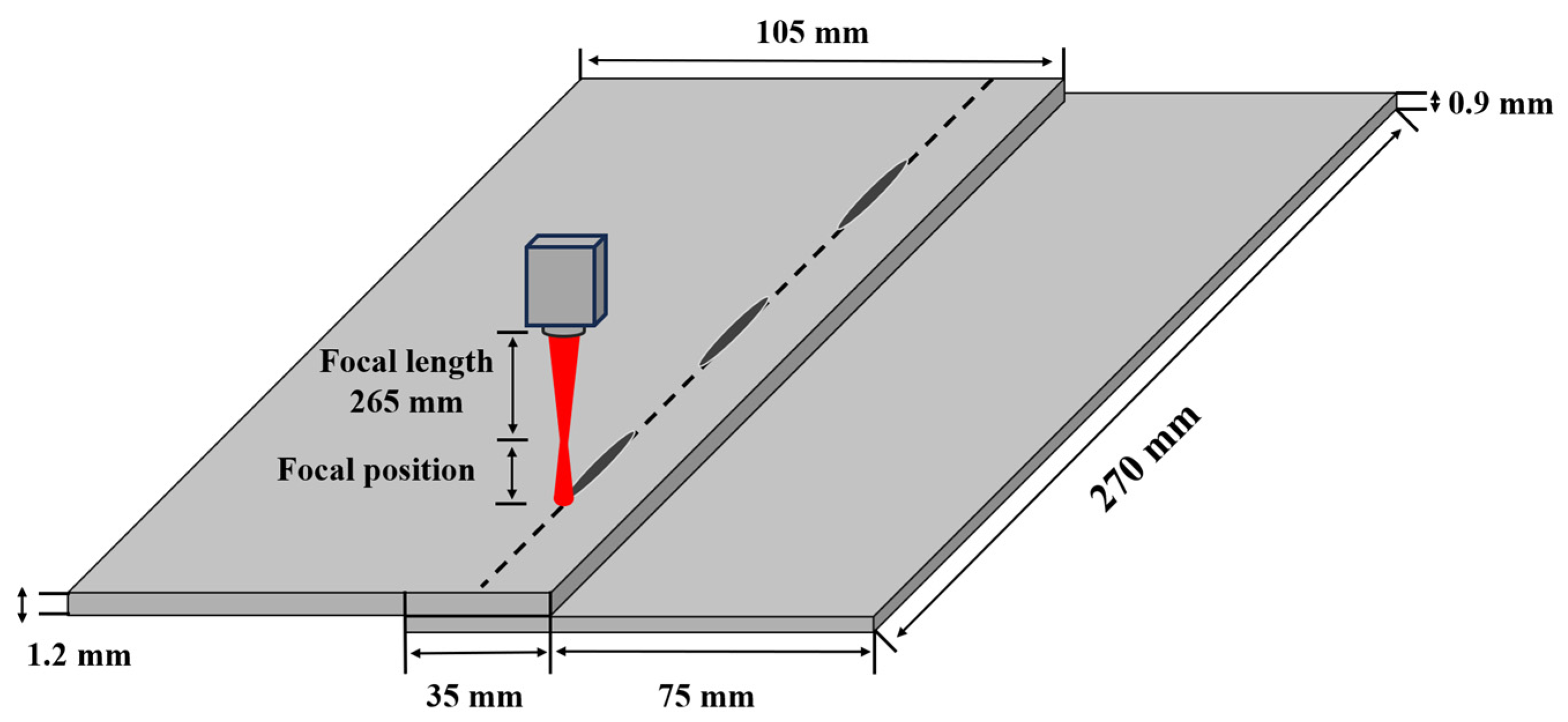
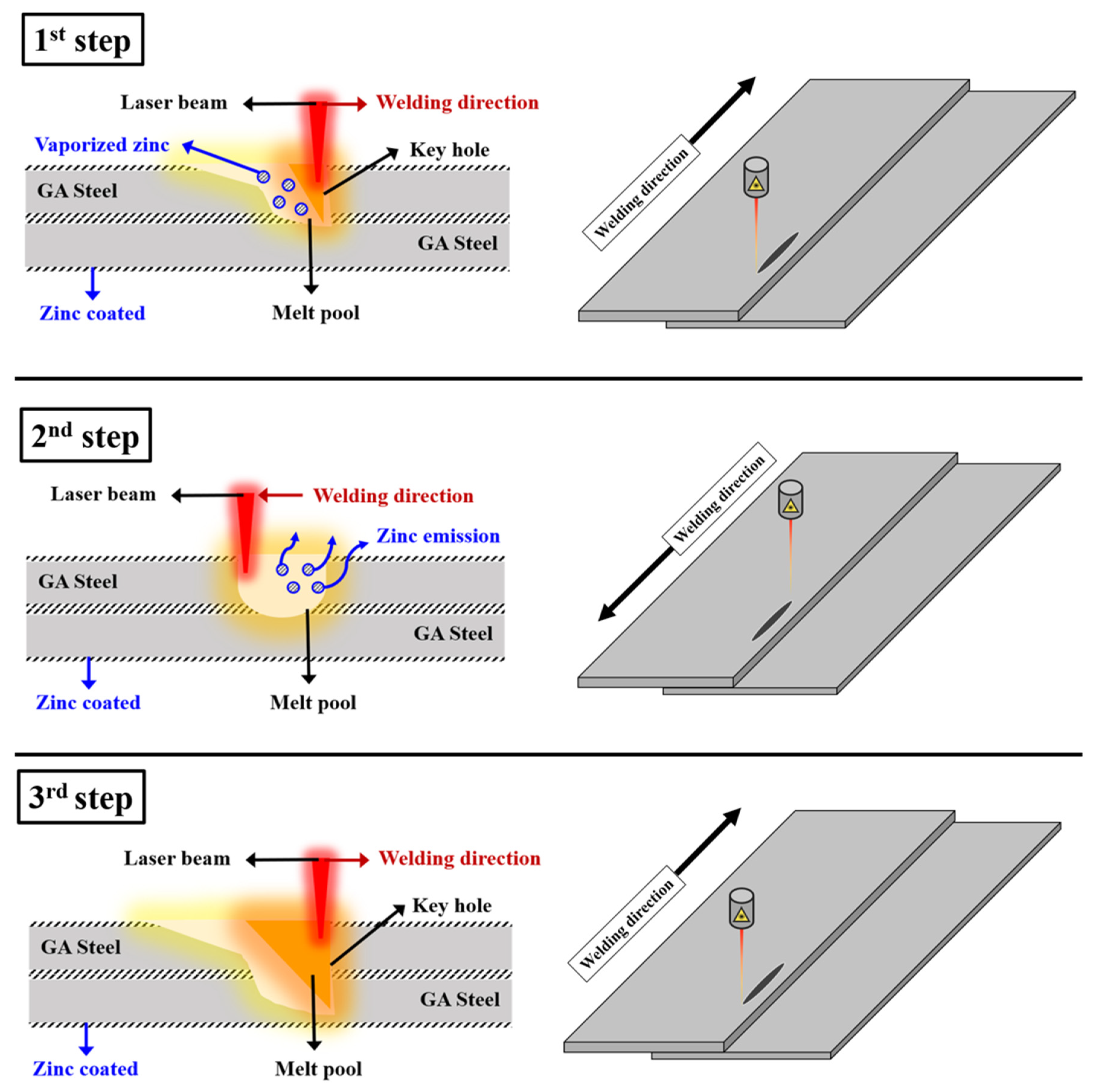
2.1. Material and Welding Method

In this study, we used galvanized steel sheets (SGARC 340) as the base metals. The upper sheet had a thickness of 1.2 mm and dimensions of 270 mm (length) × 105 mm (width), while the lower sheet was 0.9 mm thick with the same dimensions. The mechanical properties and chemical compositions of the material are shown in Table 1. As shown in Figure 1, laser stitch welding was performed with a bead length of 20 mm and an overlap length of 35 mm.

2.2. Welding Process and Conditions

The laser stitch welding process for galvanized steel sheets devised in this study consists of a total of three steps, and a detailed step-by-step schematic diagram is shown in Figure 2. The first step involves using the laser in the partial penetration mode to remove the zinc plating layer from the welds and induce zinc vaporization by melting the material down to the top surface of the lower sheet. In the second step, the laser irradiation direction is reversed and returned to the starting position. This step releases the residual zinc and pre-heats the welds by irradiating a laser beam with relatively low power. The third step is performed using the full penetration mode, ensuring a penetration depth up to the appropriate thickness of the lower sheet of the material.
In this study, laser welding was performed using a CW fiber laser (LMS, MAT-040HC, MAT, Seoul, Republic of Korea) with a maximum output power of 4 kW and a wavelength of 1070 nm. Nitrogen (N2) shielding gas was supplied with a flow rate of 10 L/min to prevent oxidation during welding. The pitch was set to 40 mm to minimize the thermal impact on subsequent stitch welds. The bead length was set to 20 mm in order to minimize thermal deformation caused by high-temperature laser welding. The first and second steps of the three-step laser welding had the fixed welding speed and laser power as shown in Table 2. These conditions were designed to remove the galvanized layer of the top and bottom surfaces of the upper sheet, which can cause defects during welding before the main welding process begins. In the final step, the welding speed was fixed at 35 mm/s, while the laser power (LP) and focal position (FP) were selected as variable process parameters. The laser power was increased from 2 to 2.8 kW at intervals of 0.4 kW, and the focal position was increased from 20 to 30 mm at intervals of 5 mm.

2.3. Evaluation Method of Weld Characteristics

In this study, we evaluated the characteristics of the weld bead, including its appearance and cross-section, to analyze how different process parameters affect welding during laser stitch welding. Additionally, we conducted tensile–shear and Vickers hardness tests to evaluate the mechanical properties. The tensile–shear test was conducted using a hydraulic tensile test machine (SHIMADZU, EHF-EG200KN-40L, Kyoto, Japan) at a loading speed of 2 mm/min. The hardness distribution was measured across the transverse direction of the weld cross-section using a micro-Vickers hardness tester (AKASHI, HM-112, Tokyo, Japan). A 500 g load was applied with a dwell time of 10 s, at intervals of 0.2 mm, starting from the welded specimen’s upper surface. To validate the pore control effect in the three-step laser stitch welding process, we conducted SEM-EDS (Scanning Electron Microscopy-Energy Dispersive Spectroscopy) analysis. The FE-SEM equipment used was the SU5000 from HITACHI, Tokyo, Japan, and the EDS equipment was the c-nano from Oxford Instruments, Oxford, UK. Additionally, internal inspection was performed using radiographic testing with the XXG-3005 unit from Dandong Huari, Dandong City, China.

3. Results and Discussion

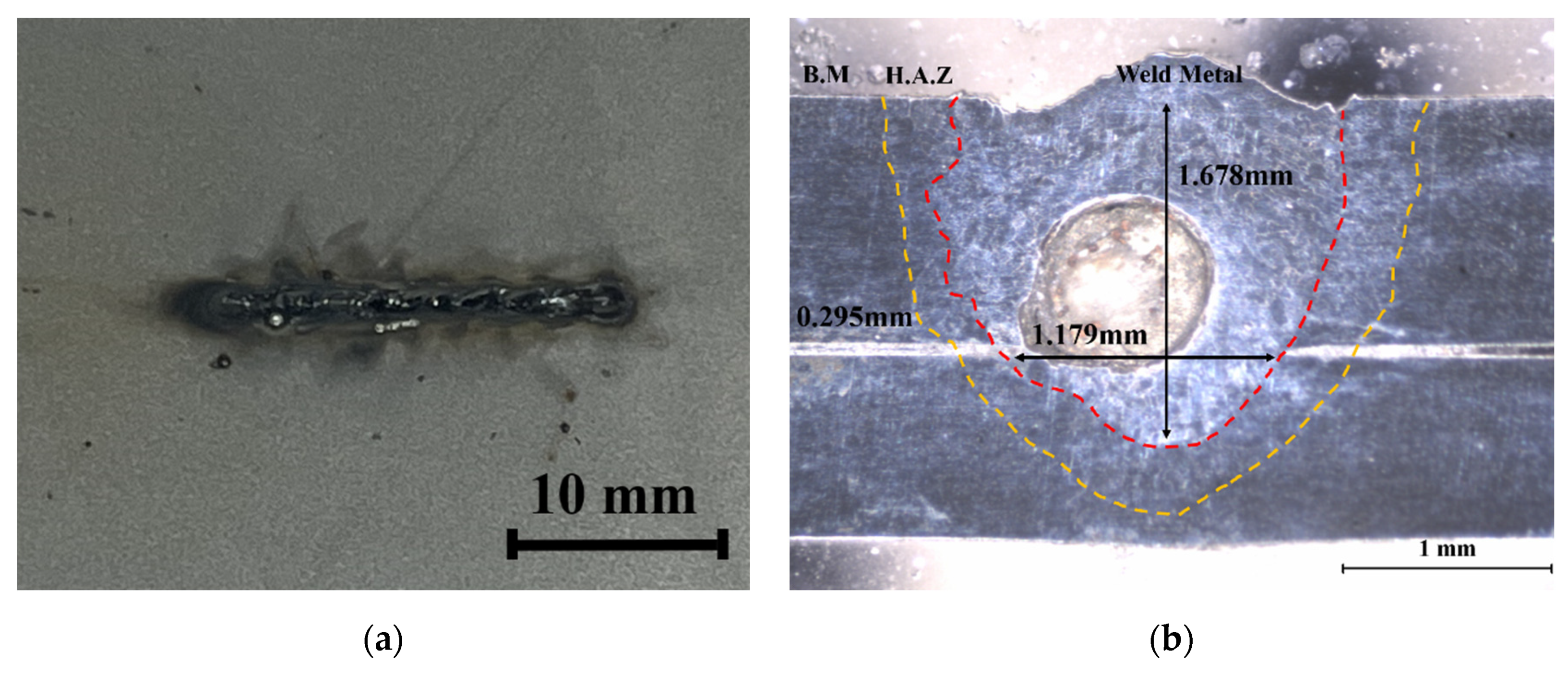
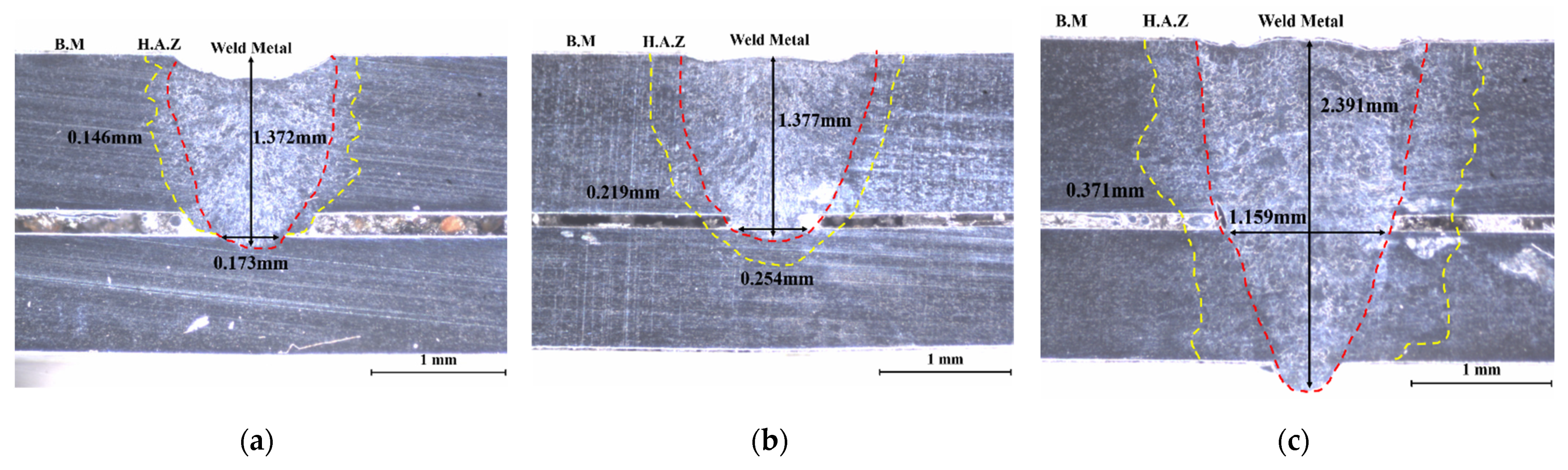
3.1. Bead Characteristics

The vaporizing point of zinc (about 907 °C) is much lower than the melting point of the steel material (about 1500 °C) [18,19]. Therefore, when fusion welding is performed on the overlap joint of the galvanized steel sheet, zinc remains in the welds due to the high viscosity of the molten pool and solidification starting from the surface of the welds, leading to welding defects due to the formation and growth of pores caused by the zinc vapor [20,21]. Figure 3 shows a cross-section image of the bead surface and the conventional laser welds that has not gone through the pretreatment step for the galvanized steel sheet. In the bead surface image, it was confirmed that the appearance quality deteriorated due to a higher number of spatters generated by the eruption of zinc vapor in the molten pool. In the cross-sectional image, internal pores that had not yet escaped from the molten pool were identified.
Figure 4 shows a cross-section image of each step in the three-step laser welding process that has gone through the pretreatment step for the galvanized steel sheet. In the cross-sections of the first and second step processes, it was confirmed that heat input was applied to the surface of the lower sheet in accordance with the purpose of removing the galvanized layer. In the cross-section image of the third step process, the main welding process was executed, and it was confirmed that complete penetration to the back side of the lower sheet material was achieved.
Table 3 shows the weld bead appearances (front bead and back bead) of the three-step laser stitch welding, along with cross-sectional images for each condition. Under all conditions, the weld beads demonstrate a more aesthetic appearance than those of traditional laser stitch welding shown in Figure 2. This is believed to result from the pre-removal of the galvanized layer, which causes spatter in steps 1 and 2 of the three-step process. Looking at each condition in detail, sufficient penetration was not secured under the laser power of 2 kW, and notably, the unwelded condition was verified at a focal position of 30 mm. In the case of the 2.4 kW laser power, a sound back bead was formed under the 20 mm focal position, but as the focal position increased, sufficient penetration was not secured. Under the 2.8 kW laser power, sufficient penetration was secured under all conditions with a focal position of 20–30 mm, and it was confirmed that a sound back bead was formed.

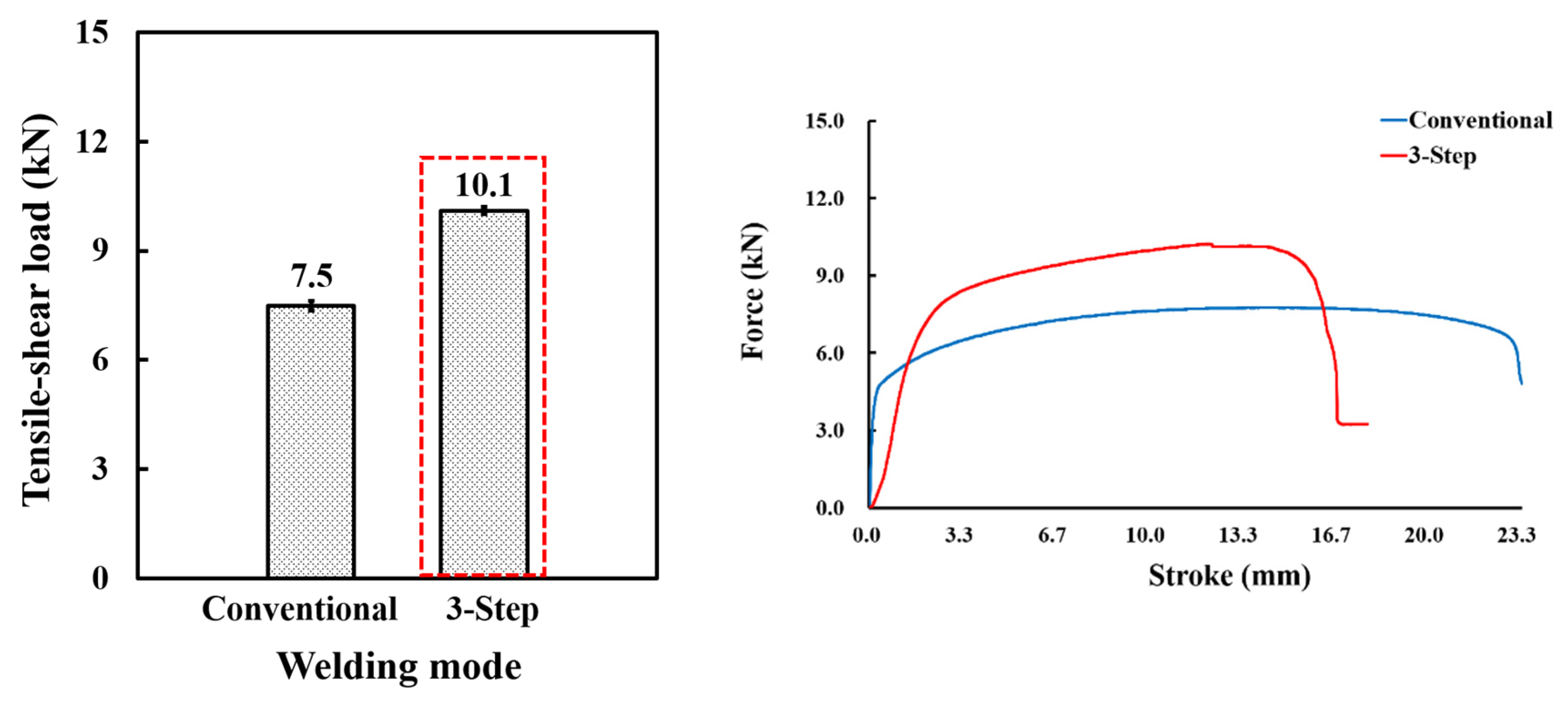
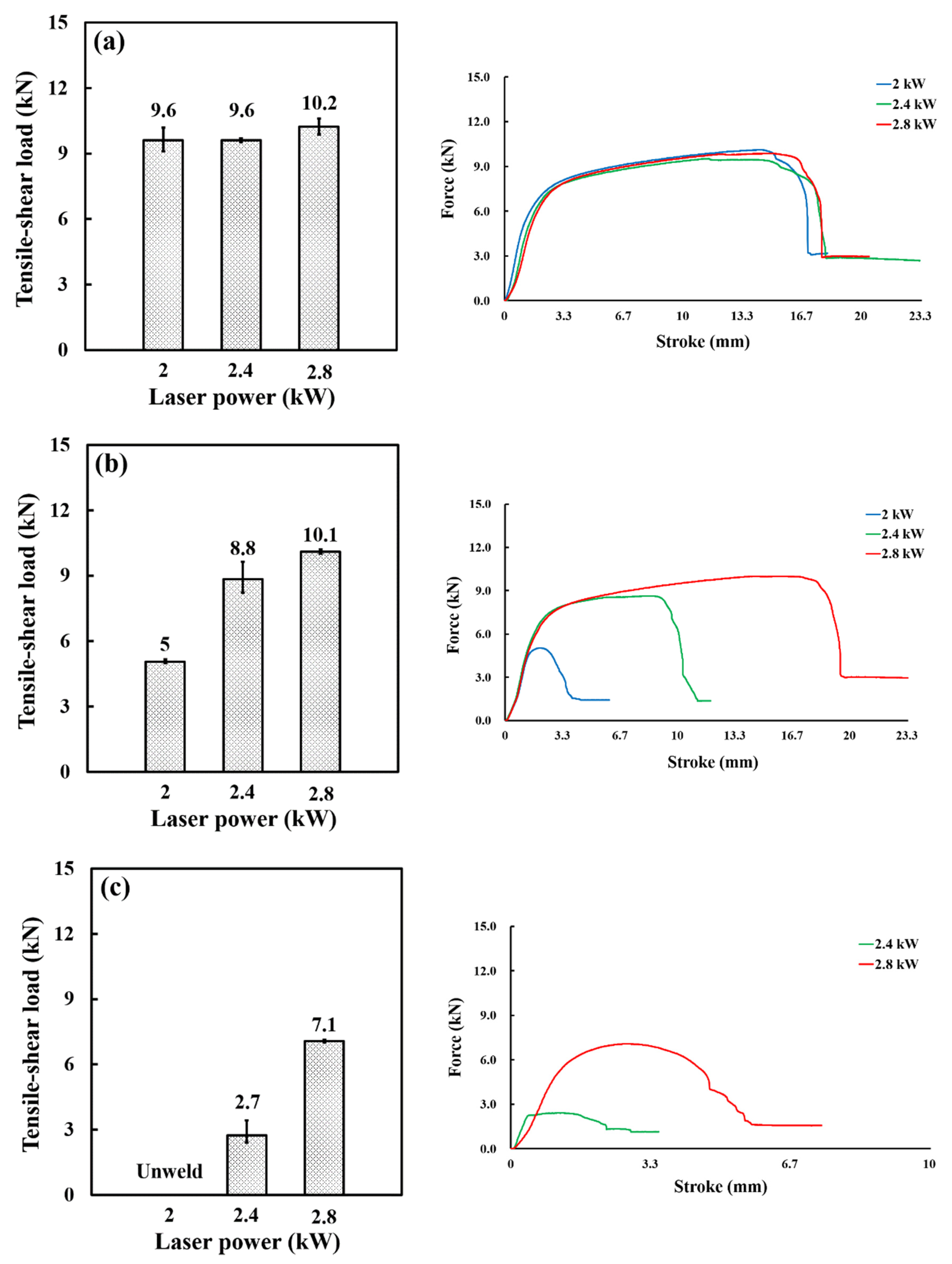
3.2. Tensile–Shear Load

As shown in Figure 5, a comparison of the tensile–shear load between conventional laser welding and three-step laser welding was conducted under the conditions of 2.4 kW laser power and focal position of 20 mm, where the best quality of the weld bead was achieved. It was confirmed that the tensile–shear load improved by approximately 37% compared to the strength of conventional laser welding. This is considered that welding defects occurred in the welds of conventional laser welding without the pre-removal step of the galvanized layer, and these are caused local stress concentration and affected tensile strength. Figure 6 shows the tensile–shear load of the three-step laser welding according to the changes in laser power and focal position conditions. As a result of comparing the tensile strength from each laser power at a focal position of 20 mm, the maximum strength value of 10.2 kN was obtained under the condition of 2.8 kW due to securing a sufficient weld area and penetration depth. In the focal position of 25 mm, the difference in tensile strength according to the laser power was clearly found, and the focal position of 30 mm was judged to be an unsuitable condition resulting from a significantly low tensile strength value or non-welding.

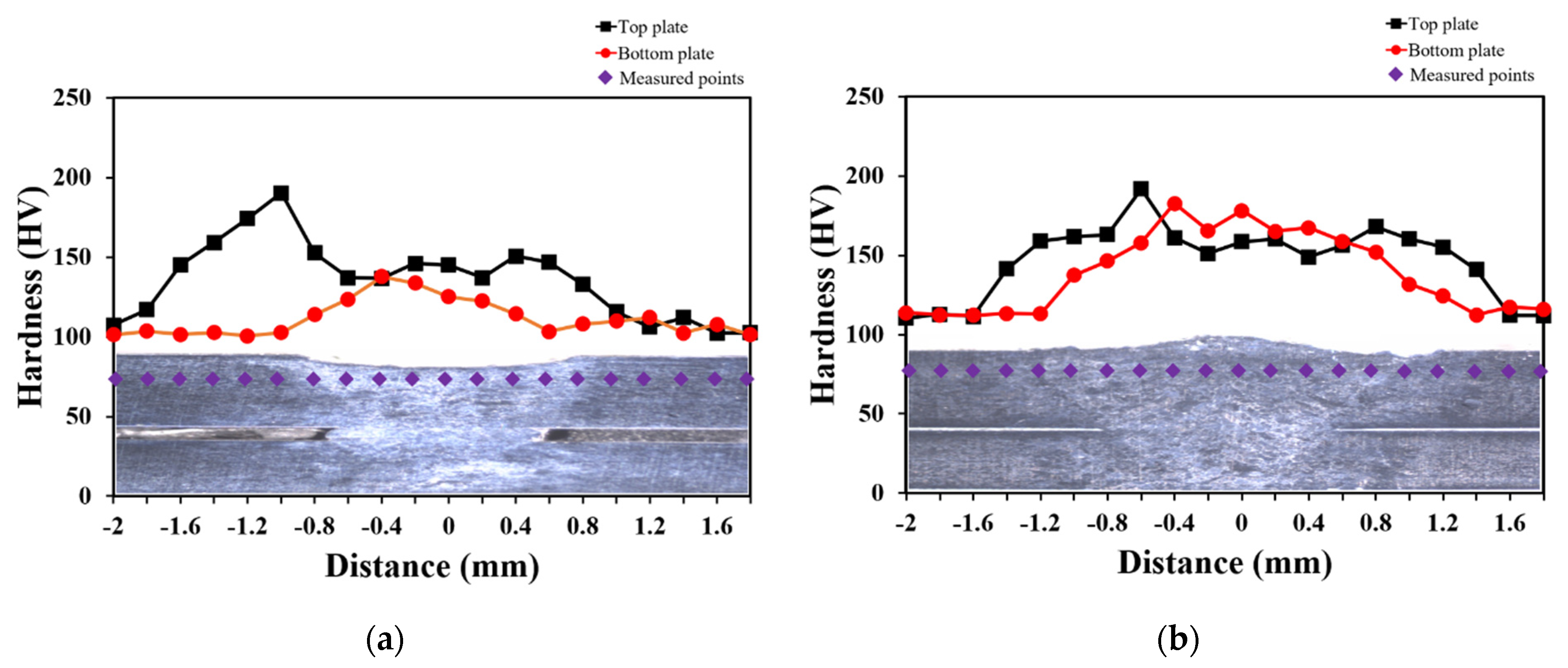
3.3. Hardness Profiles

Figure 7 shows images comparing the hardness distribution of conventional laser welding and a three-step laser welding under the conditions of 2.8 kW laser power and focal position 20 mm with the highest tensile–shearing load. The hardness distribution interval was 0.2 mm, and a total of 20 points were measured, 10 points from the left and right in the center of the welds, and the welds were divided into the weld zone and heat-affected zone. As a result of the comparison, the average hardness value of the three-step laser welds increased only slightly to about 11 HV in the upper sheet and about 27 HV in the lower sheet compared to the conventional laser welds. It is judged that the increased heat input compared to the conventional laser welding in the three-step laser welding affected the crystal grain recrystallization and growth.

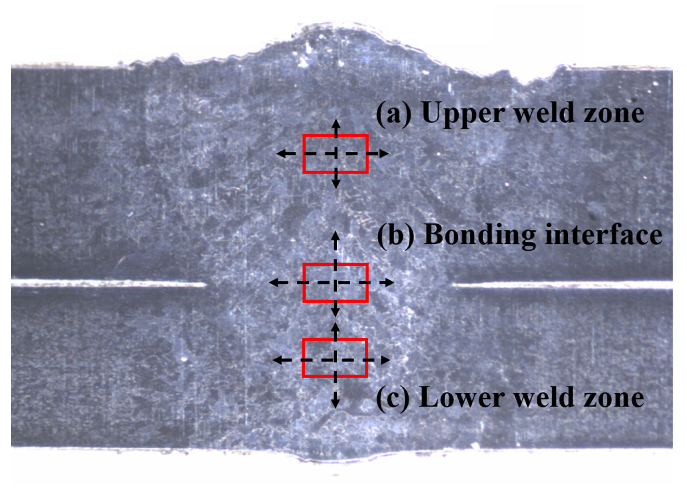
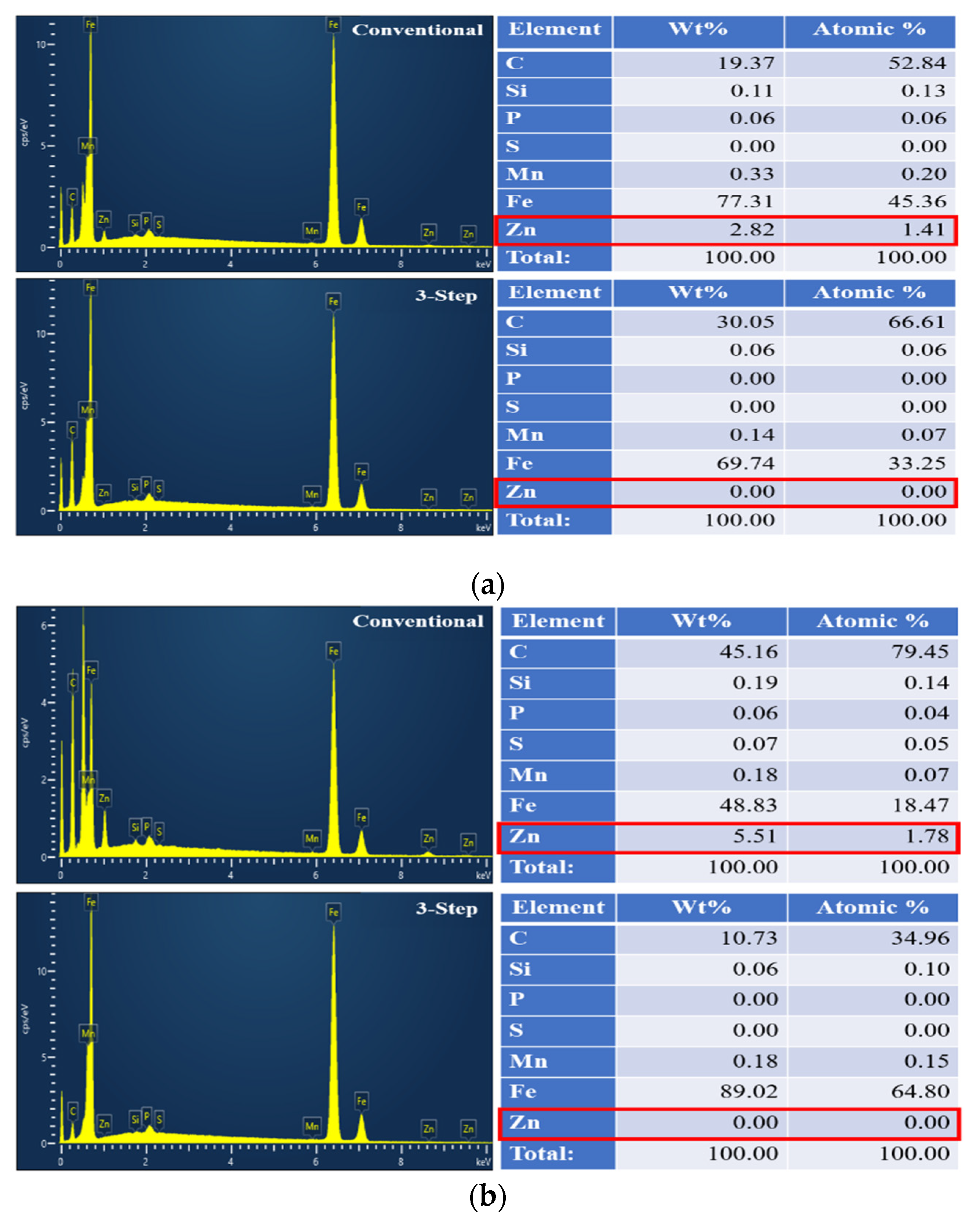
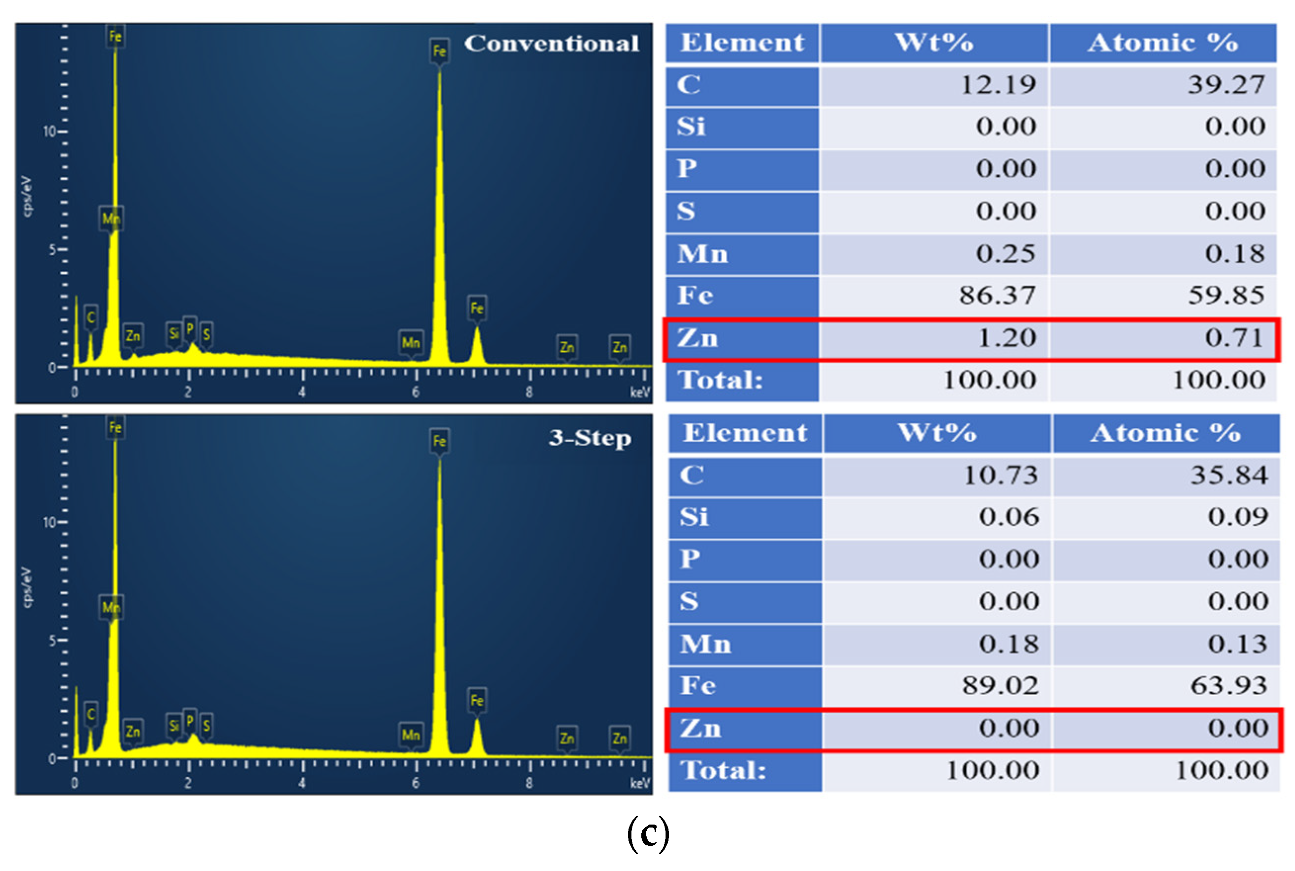
3.4. SEM-EDS Analysis

To confirm the zinc removal effect of the welds, SEM-EDS analysis was performed on the welds of both conventional and three-step laser welding. Figure 8 shows the location of the SEM-EDS measurement. Spot analysis was performed at a total of three points from the center of the welds to the upper sheet weld zone, welded bonding interface, and the lower sheet weld zone. This was performed under the conditions of the laser power of 2.8 kW and focal position of 20 mm with the highest tensile–shearing load. The component analysis results were classified into a, b, and c for each analysis location in Figure 9. For comparison, the measurement results of the conventional laser welds are shown on the left side of Figure 6, and the measurement results of the three-step laser welds are shown on the right side. The amount of zinc content at the bonding interface of the overlap joint on the galvanized steel sheet was 1.78% in the conventional laser welds and 0% in the three-step laser welds, indicating that the zinc removal effect could be quantitatively confirmed. In addition, the upper sheet weld zone, the bonding interface, and the lower sheet weld zone of the three-step laser welds all had 0% of the zinc content, whereas the amount of zinc content in conventional laser welds was, respectively, 1.41% of the upper sheet weld zone, 1.78% of the bonding interface, and 0.71% of the lower sheet weld zone. This is considered to be the case due to the fact that the zinc component melts and remains in the molten pool during the welding process.

3.5. Radiographic Testing

The radiographic testing method was utilized as a non-destructive testing technique to inspect the presence of internal pores among welding defects. The X-ray images of the conventional laser welds and the three-step laser welds under the conditions are shown in Table 4 and Table 5, respectively. As a result of radiographic testing, internal defects in the form of pores were observed in P1 and P2 of the conventional laser welds. These defects are considered to be caused by the difficult discharge of zinc vapor during the welding process. On the other hand, in the welded specimens to which the three-step laser stitch welding process devised through this study was applied, sound welds could be consistently secured, regardless of changes in the focal position. It was confirmed that this process was effective in controlling the defects caused by zinc vapor. This confirmed that three-step laser stitch welding process was effective in controlling defects caused by zinc vapor.

4. Conclusions

In this study, the reliability of weld quality was secured by comparing and analyzing weld bead, mechanical, and metallic characteristics to verify the zinc removal effect during the three-step laser stitch welding on the overlap joint of galvanized steel sheets.
  • The maximum tensile–shear strength value of 10.2 kN was obtained under the conditions of a laser power of 2.8 kW and a focal position of 20 mm in the three-step laser welding process. As a result, the tensile–shear strength value increased by about 37% compared to conventional laser welding. These results are due to the mitigation of pores in the welds by the introduction of the pre-heating step.
  • As a result of radiographic testing and SEM-EDS analysis, the three-step laser welding process effectively avoids the generation rate of internal pores due to the first and second steps of removing the galvanized layer in advance. These results indicate that zinc was not detected in welds without pores.
  • The result of the hardness profile analysis showed slightly higher at about 11 HV in the upper sheet and 27 HV in the lower sheet during three-step laser welding compared to conventional laser welding. However, it does not affect the weld quality.

Author Contributions

H.-S.B., J.-C.K., B.-S.G., D.-W.C. and H.-S.K. contributed to the study conception and design. The data analysis and manuscript were written by J.-C.K. The mechanical characteristics were investigated by D.-W.C. The metallic characteristics were investigated by H.-S.K., B.-S.G. and H.-S.B. supervised the entire work. All authors have read and agreed to the published version of the manuscript.

Funding

This paper has been written with the support of Jeollannam-do (“2022 R&D supporting program” operated by Jeonnam Technopark), development project: J0122029-03.

Institutional Review Board Statement

Not applicable.

Informed Consent Statement

Not applicable.

Data Availability Statement

Data is contained within the article.

Conflicts of Interest

The authors declare that this study received funding from Jeonnam Technopark. The funder was not involved in the study design, collection, analysis, interpretation of data, the writing of this article or the decision to submit it for publication.

References

  1. Trzepieciński, T.; Najm, S.M. Current Trends in Metallic Materials for Body Panels and Structural Members Used in the Automotive Industry. Materials 2024, 17, 590. Available online: https://www.mdpi.com/1996-1944/17/3/590 (accessed on 10 February 2024). [CrossRef]
  2. Daigo, I.; Osako, S.; Adachi, Y.; Matsuno, Y. Time-series analysis of global zinc demand associated with steel. Resour. Conserv. Recycl. 2014, 82, 35–40. Available online: https://www.sciencedirect.com/science/article/abs/pii/S0921344913002206 (accessed on 12 June 2023). [CrossRef]
  3. Ma, J.; Kong, F.; Carlson, B.; Kovacevic, R. Mitigating zinc vapor induced weld defects in laser welding of galvanized high-strength steel by using different supplementary means. In Welding Processes; IntechOpen: Rijeka, Croatia, 2012; pp. 129–134. Available online: https://www.researchgate.net/publication/300093809_Mitigating_Zinc_Vapor_Induced_Weld_Defects_in_Laser_Welding_of_Galvanized_High-Strength_Steel_by_Using_Different_Supplementary_Means (accessed on 13 June 2023).
  4. Tzeng, Y.F. Effects of operating parameters on surface quality for the pulsed laser welding of zinc-coated steel. J. Mater. Process. Technol. 2000, 100, 163–170. Available online: https://www.sciencedirect.com/science/article/pii/S0924013699004707 (accessed on 15 June 2023). [CrossRef]
  5. Matsui, H.; Suzuki, H.; Yamada, M. Reduction of blowholes in high-speed arc welding of hot-dip galvanised steel sheets. Weld. Int. 1998, 12, 432–439. Available online: https://www.tandfonline.com/doi/abs/10.1080/09507119809448511 (accessed on 12 June 2023). [CrossRef]
  6. Ma, G.; Yu, X.; Ye, J.; He, Y.; Xiao, Y. Effect of alloy elements on the weld of galvanised sheet studied by first-principles. Mater. Sci. Technol. 2020, 36, 1139–1147. Available online: https://journals.sagepub.com/doi/full/10.1080/02670836.2020.1755778 (accessed on 6 July 2023). [CrossRef]
  7. Singh, J.; Khan, M.S.; Oliveira, J.P.; Arora, K.S. Brazing of high-strength steels: Recent developments and challenges. J. Manuf. Process. 2023, 145, 021014. Available online: https://www.sciencedirect.com/science/article/pii/S1526612524001361 (accessed on 12 July 2023). [CrossRef]
  8. Kam, D.H.; Lee, T.H.; Kim, J. Porosity reduction through a Ti particle based gap-paste in arc welding of zinc coated steel. J. Mater. Process. Technol. 2018, 258, 211–219. Available online: https://www.sciencedirect.com/science/article/pii/S0924013618301274 (accessed on 17 July 2023). [CrossRef]
  9. Mohammadpour, M.; Yang, B.; Wang, H.P.; Forrest, J.; Poss, M.; Carlson, B.; Kovacevic, R. Influence of laser beam inclination angle on galvanized steel laser braze quality. Opt. Laser Technol. 2020, 129, 106303. Available online: https://www.sciencedirect.com/science/article/abs/pii/S0030399220304266 (accessed on 22 July 2023). [CrossRef]
  10. Xiong, W.; Zhang, P.; Yu, Z.; Yan, H.; Wu, D.; Lu, Q.; Tian, Y. Weld zone porosity elimination process of galvanized steel zero-gap lap joints in remote laser spiral welding. Mater. Res. Express 2021, 8, 066502. Available online: https://iopscience.iop.org/article/10.1088/2053-1591/ac04ee/meta (accessed on 24 July 2023). [CrossRef]
  11. Garcia-Guerrero, J.C.; Curiel-López, F.F.; López-Morelos, V.H.; Taha-Tijerina, J.J.; Sánchez-Cruz, T.J.; Ramirez-Lopez, M.D.C.; Eduardo Cortes-Carillo, E.; Quinones-Salinas, M.A. Impact of Welding Parameters in the Porosity of a Dissimilar Welded Lap Joint of CP800-XPF1000 Steel Weldment by GMAW-P. Metals 2024, 14, 309. Available online: https://www.mdpi.com/2075-4701/14/3/309 (accessed on 20 February 2024). [CrossRef]
  12. Graham, M.P.; Hirak, D.M.; Kerr, H.W.; Weckman, D.C. Nd: YAG laser beam welding of coated steels using a modified lap joint geometry. Weld. J. Incl. Weld. Res. Suppl. 1996, 75, 162s. Available online: https://pascal-francis.inist.fr/vibad/index.php?action=getRecordDetail&idt=3186530 (accessed on 24 June 2023).
  13. Gu, H.; Mueller, R. Hybrid welding of galvanized steel sheet. In Proceedings of the International Congress on Applications of Lasers & Electro-Optics, Orlando, FL, USA, 14–18 October 2018; pp. 135–139. Available online: https://pubs.aip.org/liacp/proceedings-abstract/ICALEO/2001/135/1074934 (accessed on 20 June 2023).
  14. Li, X.; Lawson, S.; Zhou, Y.; Goodwin, F. Novel technique for laser lap welding of zinc coated sheet steels. J. Laser Appl. 2007, 19, 259–264. Available online: https://pubs.aip.org/lia/jla/article-abstract/19/4/259/220680/Novel-technique-for-laser-lap-welding-of-zinc (accessed on 15 August 2023). [CrossRef]
  15. Han, S.-W.; Kim, H.; Lee, G.; Shin, S.; Jeon, J.; Han, S.; Bae, G.; Cho, J. GMA process development for pore-free zinc-coated steel sheet welding in automotive industry. Int. J. Adv. Manuf. Technol. 2023, 126, 3849–3859. Available online: https://link.springer.com/article/10.1007/s00170-023-11338-9 (accessed on 18 August 2023). [CrossRef]
  16. Ma, J.; Kong, F.; Carlson, B.; Kovacevic, R. Two-pass laser welding of galvanized high-strength dual-phase steel for a zero-gap lap joint configuration. J. Mater. Process. Technol. 2013, 213, 495–507. Available online: https://www.sciencedirect.com/science/article/pii/S092401361200324X (accessed on 9 September 2023). [CrossRef]
  17. Young-Nam, A.; Kang, M.; Kim, C. Applicability Study of 2-pass Laser Welding on Galvanized Steel Sheets. J. Weld. Join. 2016, 34, 55–61. Available online: https://www.e-jwj.org/journal/view.php?number=2031765 (accessed on 11 October 2023).
  18. Yu, J.; Kim, D. Effects of welding current and torch position parameters on minimizing the weld porosity of zinc-coated steel. Int. J. Adv. Manuf. Technol. 2018, 95, 551–567. Available online: https://link.springer.com/article/10.1007/s00170-017-1180-6 (accessed on 15 October 2023). [CrossRef]
  19. Deng, S.; Guo, Q.; Wang, H.P.; Lu, F.; Solomon, J.; Carlson, B.E. Effectiveness of pre-scanning on zinc evaporation in laser spot welding of zinc-coated steels. Int. J. Adv. Manuf. Technol. 2020, 106, 4423–4436. Available online: https://link.springer.com/article/10.1007/s00170-019-04891-9 (accessed on 6 November 2023). [CrossRef]
  20. Kim, C.; Choi, W.; Kim, J.; Rhee, S. Relationship between the weldability and the process parameters for laser-TIG hybrid welding of galvanized steel sheets. Mater. Trans. 2008, 49, 179–186. Available online: https://www.jstage.jst.go.jp/article/matertrans/49/1/49_MER2007159/_article/-char/ja/ (accessed on 6 December 2023). [CrossRef]
  21. Hao, Y.; Wang, H.P.; Sun, Y.; Li, L.; Wu, Y.; Lu, F. The evaporation behavior of zinc and its effect on spattering in laser overlap welding of galvanized steels. J. Mater. Process. Technol. 2022, 306, 117625. Available online: https://www.sciencedirect.com/science/article/pii/S0924013622001376 (accessed on 9 December 2023). [CrossRef]
Figure 1. Dimensions of the weldment specimen.
Applsci 14 02987 g001
Figure 2. Schematic diagram of the three-step laser welding process.
Applsci 14 02987 g002
Figure 3. Bead appearance and cross-section of conventional laser welds: (a) bead appearance; (b) cross-section. B.M (Base Metal) refers to the area outside the yellow line. H.A.Z (Heat Affected Zone) denotes the area between the yellow and red lines. Weld Metal signifies the section inside the red line.
Applsci 14 02987 g003
Figure 4. Cross-section of each step in the three-step laser welding process: (a) one-step process; (b) two-step process; (c) three-step process. B.M (Base Metal) refers to the area outside the yellow line. H.A.Z (Heat Affected Zone) denotes the area between the yellow and red lines. Weld Metal signifies the section inside the red line.
Applsci 14 02987 g004
Figure 5. Comparison of tensile–shear load with different welding methods. The red dashed line indicates the welding mode.
Applsci 14 02987 g005
Figure 6. Comparison of tensile–shear load under different welding conditions during three-step laser welding: (a) focal position 20 mm; (b) focal position 25 mm; (c) focal position 30 mm.
Applsci 14 02987 g006
Figure 7. Hardness distribution with welding method: (a) hardness profile for conventional laser welds; (b) hardness profile for three-step laser welds.
Applsci 14 02987 g007
Figure 8. Analysis spots of SEM-EDS. The letters (a), (b) and (c) indicate the measurement locations in Figure 9.
Applsci 14 02987 g008
Figure 9. Comparison of the EDS spectrum with different welding methods: (a) upper weld zone; (b) bonding interface; (c) lower weld zone.
Applsci 14 02987 g009aApplsci 14 02987 g009b
Table 1. Chemical compositions and mechanical properties of SGARC340.
Chemical Composition (wt%)
CSiMnPTiS-AL
0.0010.0480.0050.010.430.033
Mechanical Properties
Tensile Strength (MPa)Yield Strength (MPa)Elongation (%)
35919839%
Table 2. Welding conditions used for three-step laser stitch welding.
Welding ConditionStep
123
Laser power, LP (kW)1.60.82.0, 2.4, 2.8
Focal position, FP (mm)20, 25, 3020, 25, 3020, 25, 30
Welding speed (mm/s)306035
Bead length (mm)20
Shielding gas (L/min)10
Focal length (mm)265
Pitch (mm)40
Table 3. Bead appearance and cross-section of three-step laser welds.
LP (kW)FP (mm)Front BeadBack BeadCross Section
220Applsci 14 02987 i001Applsci 14 02987 i002Applsci 14 02987 i003
225Applsci 14 02987 i004Applsci 14 02987 i005Applsci 14 02987 i006
230Applsci 14 02987 i007Applsci 14 02987 i008Unweld
2.420Applsci 14 02987 i009Applsci 14 02987 i010Applsci 14 02987 i011
2.425Applsci 14 02987 i012Applsci 14 02987 i013Applsci 14 02987 i014
2.430Applsci 14 02987 i015Applsci 14 02987 i016Applsci 14 02987 i017
2.820Applsci 14 02987 i018Applsci 14 02987 i019Applsci 14 02987 i020
2.825Applsci 14 02987 i021Applsci 14 02987 i022Applsci 14 02987 i023
2.830Applsci 14 02987 i024Applsci 14 02987 i025Applsci 14 02987 i026
Table 4. X-ray radiograph of conventional laser welds.
Welding ConditionRadiographic Testing
LP (kW): 2.4
FP (mm): 20
Applsci 14 02987 i027
Table 5. X-ray radiographs of the three-step laser welds.
Welding ConditionRadiographic Testing
LP (kW): 2.4
FP (mm): 20
Applsci 14 02987 i028
LP (kW): 2.4
FP (mm): 25
Applsci 14 02987 i029
LP (kW): 2.4
FP (mm): 30
Applsci 14 02987 i030
Disclaimer/Publisher’s Note: The statements, opinions and data contained in all publications are solely those of the individual author(s) and contributor(s) and not of MDPI and/or the editor(s). MDPI and/or the editor(s) disclaim responsibility for any injury to people or property resulting from any ideas, methods, instructions or products referred to in the content.

