1. Introduction
In the realm of electrochemical energy storage and conversion technology, the supercapacitor is one of the renowned systems for its practicality and versatility. Supercapacitors are distinguished from other electrochemical energy storage systems by offering a unique balance of high-power capabilities, exceeding that of batteries, along with enhanced energy density compared to traditional capacitors [
1]. Based on the charge storage mechanism, supercapacitors are categorized as electric double-layer capacitors (EDLCs), pseudo-capacitors, and hybrid supercapacitors.
EDLCs exhibit high power density and cycle life, which are attributed to the efficient separation of charges through electrostatic attraction within the electrochemical double layer. EDLCs generally employ activated carbon-based nanomaterials with high surface area and electrical conductivity in their electrodes to facilitate the rapid movement of ions and electrons [
2]. The nanometer-scale pore size plays a pivotal role in reducing charge separation distances, consequently leading to increased capacitance [
3]. Consequently, a common strategy involves the fabrication of nanostructured electrodes to bolster electrode material conductivity [
4] while simultaneously reducing diffusion pathways [
5], with specific surface area serving as a direct determinant of specific capacitance. In contrast, Pseudo capacitors employ electrode materials consisting of conductive polymers and transition metal oxides to store charge through surface-controlled faradaic reactions taking place at the electrode–electrolyte interface at rates comparable to those of electrochemical double-layer formation in EDLCs. The architecture and composition of electrode materials have a significant impact on the performance of supercapacitors. Various electrode materials with different dimensional structures such as 0D, 1D, 2D, and 3D have been designed to enhance their performance. Among them, 1D nanomaterials synthesized by the electrospinning method show promising potential due to their easy preparation, high aspect ratio, which facilitates efficient electron and mass transportation, and strong plasticity. The composite materials synthesized using carbon materials, carbide materials, conductive polymers, sulfides, nitrides, metal oxides, etc., show better electrochemical performance due to their high stability, conductivity, and electron storage capacity [
6,
7]. In general, transition metal oxides offer higher capacitance than carbon materials and superior charge-discharge cycle stability compared to polymers, despite their lower electronic conductivity [
8]. Among transition metal oxides, NiO is a popular choice as a pseudo-capacitor electrode material due to its high theoretical capacitance, large surface area, cycling stability, multi-oxidation states, and reversible redox reactions [
7]. However, NiO grapples with challenges such as low electronic conductivity, limited redox active sites, and a low charge/discharge ratio, which inevitably impact capacitance and cycling performance. To address these issues, strategies have been explored, including the nanostructuring of NiO electrodes to enhance the effective surface area, hybridization with highly conductive carbon-based materials, and doping with foreign elements [
9]. Various studies have been reported to enhance the capacitance of capacitors by using NiO-based composite materials. For instance, R. D. Noce and coworkers achieved 150 F g
−1 capacitance using NiO/CNF with Na
2SO
4 as electrolyte [
10], T. Hussain et al. reported 157.9 F g
−1 with CNF-NiO [
11], and 742.2 F g
−1 capacitance was reported by S. Shin and coworkers [
12].
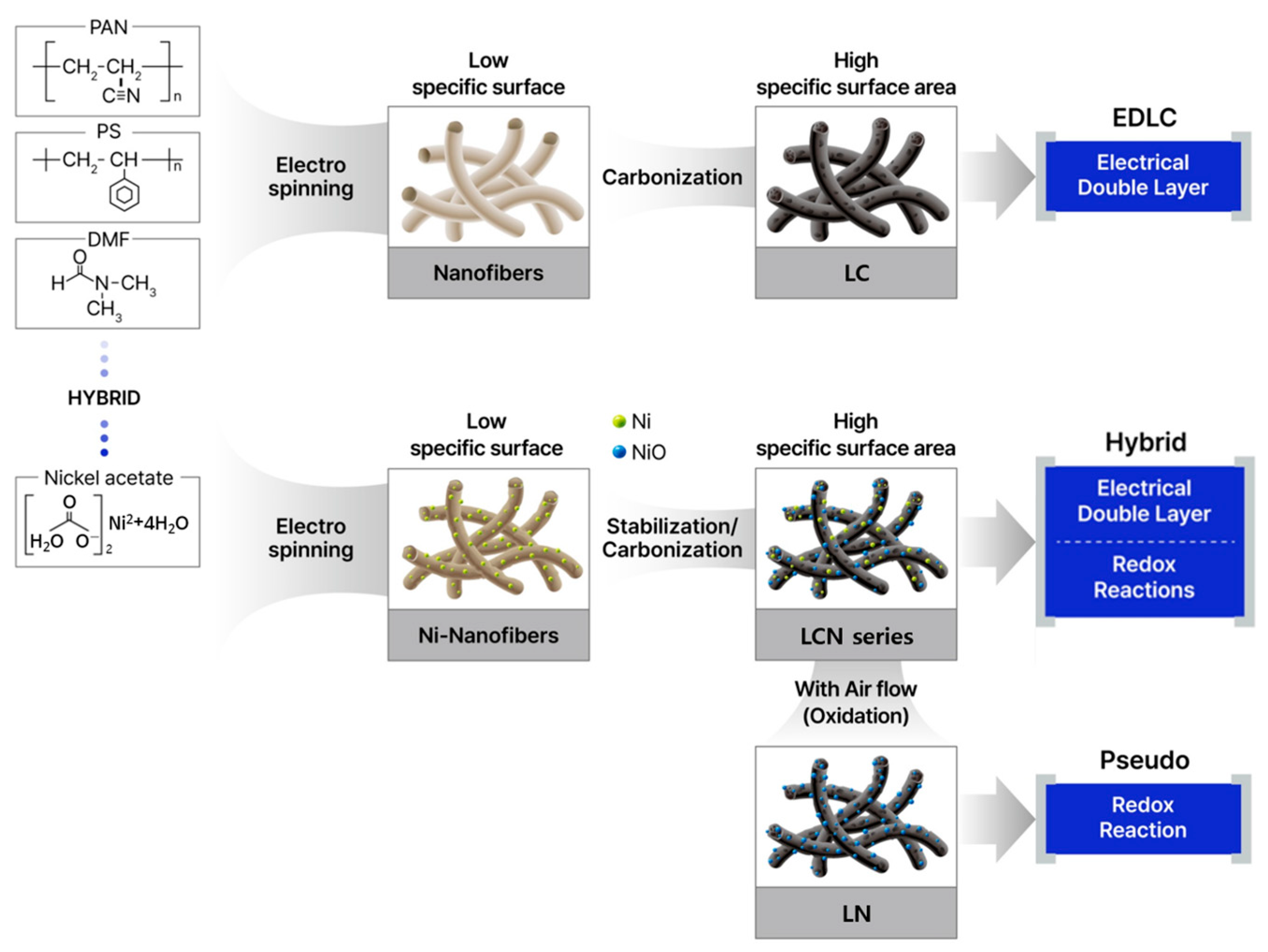
In our study, we have developed a hybrid Nickel oxide-carbon nanofiber (NiO-CNF) hybrid capacitor electrode, notably for its rectangular shape observed in cyclic voltammetry (CV), stable operating voltage, high energy, low cost, self-balancing, and close resemblance to the ideal characteristics of a capacitor [
13]. Moreover, the NiO-CNFs hybrid capacitor exhibited significantly faster charge and discharge rates compared to bare NiO. This notable improvement can be attributed to enhancements in both the redox reaction kinetics and the electrode’s resistivity. The superior electronic conductivity of CNF in comparison to NiO played an important role in achieving this enhanced performance. Specifically, the inclusion of Polystyrene (PS) in the synthesis process led to the development of internal lotus root-like pores in CNF during the subsequent heat treatment process, which encompassed oxidation stabilization and carbonization. Additionally, this process resulted in the formation of numerous surface curvatures, akin to a chemical etching effect. This enhancement in specific surface area was strategically designed to mitigate the internal resistance of the electrode, consequently boosting the overall capacitance of the supercapacitor. The porous structure of carbon materials was found to exert a profound influence on the mobility of ions within pores, with small pores hampering ion transport [
14]. Hybrid capacitors combine the strengths of EDLC and pseudo-capacitors, utilizing different electrochemical materials with varying working potentials for higher energy and power densities. They can be created using various electrode material combinations [
15]. The investigation demonstrates that the superior performance of micropores (<2 nm) persists over mesopores (2–50 nm), even in instances where mesopores undergo fine-tuning to achieve a carbon structure. Improved capacitance can be facilitated through the process of partial desolvation, accessed by the pores measuring less than 2 nm within the microporous structure [
16]. We synthesized Polyacrylonitrile (PAN)-based nanofibers containing Ni and PS through electrospinning, with subsequent heat treatment to remove the PS polymer and form nanopores, thereby augmenting the specific surface area. The process results in a lotus root-type NiO-CNFs nanocomposite. The utilization of PS proved to be effective in enhancing the specific surface area of CNFs, a fact corroborated by various analytical techniques [
17]. This facilitated a comprehensive comparison of material properties between NiO and carbon after the carbonization process [
18].
2. Materials and Methods
2.1. Material Preparation
The first step in the experimental procedure was to dissolve the solute in a solvent to synthesize a polymer solution for electrospinning, and the following materials were used to prepare the active material. To prepare the carbonized material, polyacrylonitrile (PAN) (150,000 g/mol, Sigma-Aldrich, St. Louis, MO, USA), polystyrene (PS) (192,000 g/mol, Sigma-Aldrich), and nickel(II) acetate tetrahydrate (99.995%, Sigma-Aldrich) were used as solutes, dimethylformamide (N,N-Dimethylformamide, DMF) (99.5%, JUNSEI, Tokyo, Japan) was used as a solution, and nanofibers were manufactured using an electrospinning/spraying system (eS-robot, NanoNC, Seoul, Republic of Korea).
During the experiment, the operation was conducted in an environment where the temperature and relative humidity were kept constant at 25 °C and 50%, respectively. The nozzle tip through which the polymer solution was discharged was 0.33 mm, the discharge rate of the solution was 30 μL min
−1, and the voltage applied to the nozzle tip at this time was DC 20.0 kV. The polymer fibers manufactured through electrospinning are heated to 250 °C at 6 °C min
−1 in normal air through a sample-sintering electric furnace (Box Furnace, K-TEC, Incheon, Republic of Korea), and then undergo an oxidation stabilization step and are thermally decomposed in a carbonization process at 1000 °C [
19].
In the case of high-elasticity fibers, a higher temperature is required [
20]. The carbon fiber manufacturing process involves a carbonization process in which the PAN polymer fiber is graphitized at a high temperature and converted into a carbon structure with a purity of at least 99% [
21]. The secondary heat treatment for the carbonization process was performed at 1000 °C for 1 h in a hydrogen gas atmosphere at a flow rate of 500 mL min
−1 in a tube furnace (ScienTech, Suwon, Republic of Korea).
Figure 1 is a schematic diagram of the material manufacturing process.
Heat treatment for the oxidation of nickel metal was carried out at 400 °C and 450 °C for 30 min at a heating rate of 6 °C min−1, respectively, to obtain NiO/C samples. The powder produced by PAN/PS was named Lotus-root-typed Carbon nanofiber (LC). The sample types were divided into 0.5 g and 0.7 g depending on the nickel content with 8 mL of DMF and 1.0 g of PAN, and the heat treatment temperature was set at 400 °C and 450 °C to classify the sample types. The nomenclature of the Lotus-root-typed Carbon Nickel oxide nanofiber (LCN) series is based on the nickel content remaining after the removal of carbon by TGA and is divided into LCN-35 (35.6%), LCN-40 (40.3%), LCN-45 (45.5%), and LCN-48 (48.6%). In addition, a sample containing nickel content is additionally heat-treated in a normal atmospheric atmosphere, leaving only a trace amount of carbon necessary to maintain the shape of the lotus root structure, and is named lotus-root-typed nickel oxide nanofiber (LN).
2.2. Material Characterization
The morphology of samples was investigated through the use of a field emission scanning electron microscope (FE-SEM) (S-4800, Hitachi, Tokyo, Japan). High-resolution X-ray diffraction (XRD) patterns were acquired employing a state-of-the-art X-ray diffractometer (HRXRD, X’pert Pro MRD, PANalytical, Tokyo, Japan) and analyzed using Cu-Kα radiation within the range of 10° ≤ 2θ ≤ 90° at a scanning rate of 2° min−1. Thermogravimetric Analysis (TGA) (TGA 2050, TA Instruments, New Castle, DE, USA) was used to analyze the quantitative content of carbon and nickel/nickel oxide, and each sample was heated from room temperature to 800 °C at a rate of 6 min−1 under normal air atmosphere. N2 adsorption/desorption isotherms were obtained using an automated specific surface area and pore size distribution analyzer (BELSORP-mini II, MicrotracBEL, Osaka, Japan). The specific surface area and pore properties of the samples were assessed employing the Brunauer–Emmett–Teller (BET) and Barrett–Joyner–Halenda (BJH) methods.
2.3. Electrochemical Characterization
The supercapacitor electrode is made by spreading a slurry composed of NiO-CNFs nanocomposites, a conductive material (super-P), styrene-butadiene rubber (SBR), and carboxymethyl cellulose (CMC) binder in a weight ratio of 80:10:10 on a 1 × 1 cm2 nickel metal foil. The mass of active material within the slurry was 0.92 mg, 0.51 mg, 0.53 mg, 0.36 mg, 0.48 mg, and 0.90 mg after drying for LC, LCN-35, LCN-40, LCN-45, LCN-48, and LN, respectively. It was manufactured by casting and the casted electrode was placed in a vacuum oven and dried at 100 °C for 1 h. In addition to the manufactured working electrode, a counter electrode and reference electrode were used to form a three-electrode system with platinum and Hg/HgO, respectively. When evaluating the electrochemical properties, 6 M KOH was applied as the electrolyte.
Cyclic voltammetry (CV) was measured in the voltage range of 0.25 to 0.5 V. Galvanostatic charge/discharge (GCD) characteristics of the electrode were performed between 0 and 0.45 V. The scan rates for CV and GCD were 2 to 100 mV s−1 and 0.2–3.0 A g−1, respectively. Long-term cycle life was performed with GCD measurements for 1000 cycles with a current density of 1.0 A g−1.
The capacitance value (
Cm) determined as the area of the cyclic voltammetric curve was calculated for each scanning speed according to Equation (1).
Here,
Cm is the mass of the active electrode material [
g],
v is the scan rate [V/s],
i(
E) is the respective current [A], and
E2 −
E1 is Δ
V [
V] the voltage of one scanning portion. From the time potential difference curve of the constant current charge/discharge curve, the weight-based capacitance (
Cm) is calculated according to Equation (2).
Here,
Cm is the total capacitance [
F],
I is the discharge current value [A], Δ
t is the discharge time [s],
m is the mass of the working electrode active material [g], and Δ
V [
V] is the potential change excluding the IR drop within Δ
t [
22]. Additionally, to determine the internal resistance that impedes the flow of electrons, EIS was measured in the frequency range of 100,000 to 0.1 Hz with an amplitude voltage of 5 mV using IVUM STAT (HS Technologies, Plano, TX, USA).
3. Results and Discussion
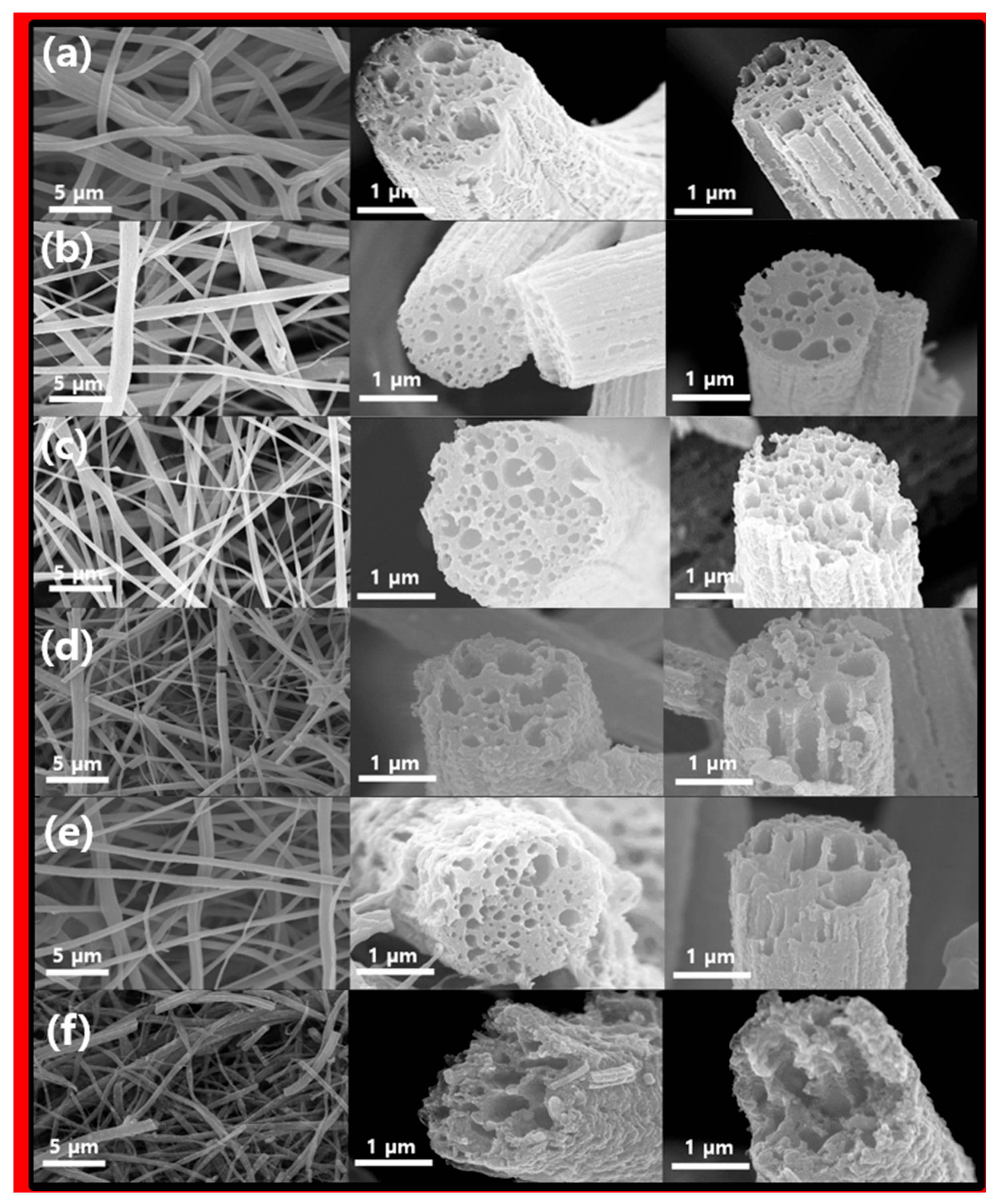
The color of the nanofiber produced by electrospinning was initially white and later changed to yellow or brown through oxidation stabilization heat treatment, and the sample after final carbonization was black. The morphological characteristics of the final carbonization samples were observed using a field emission-scanning electron microscope (FE-SEM), and the corresponding images are presented in
Figure 2. When viewed at a low magnification, the samples showed long nanofibers with diameters ranging from 700 nm to 1.5 μm. Additionally, these fiber samples displayed numerous internal pores and noticeable waviness on the fiber surface. This suggests that in contrast to CNFs fabricated solely from PAN [
23], the portion of fibers containing PS is removed during the heat treatment, as shown in
Figure 2a. PS is removed as it decomposes, and during this process, it plays an important role in forming the lotus root shape and additionally forms the internal pores and external etched surface of the electrospun nanofiber. This removal process results in the formation of internal pores and surface curvature in the CNFs. Interestingly,
Figure 2b–e, illustrating various Ni content levels and temperature differences during the third heat treatment process, did not exhibit significant morphological distinctions. However,
Figure 2f, where carbon was entirely removed, leaving only NiO, exhibited intensified fiber destruction and surface curvature. Nonetheless, it was apparent that the fiber’s morphology, including internal pores, was retained, similar to the CNF sample. These findings suggest that CNFs acted as a morphological template.
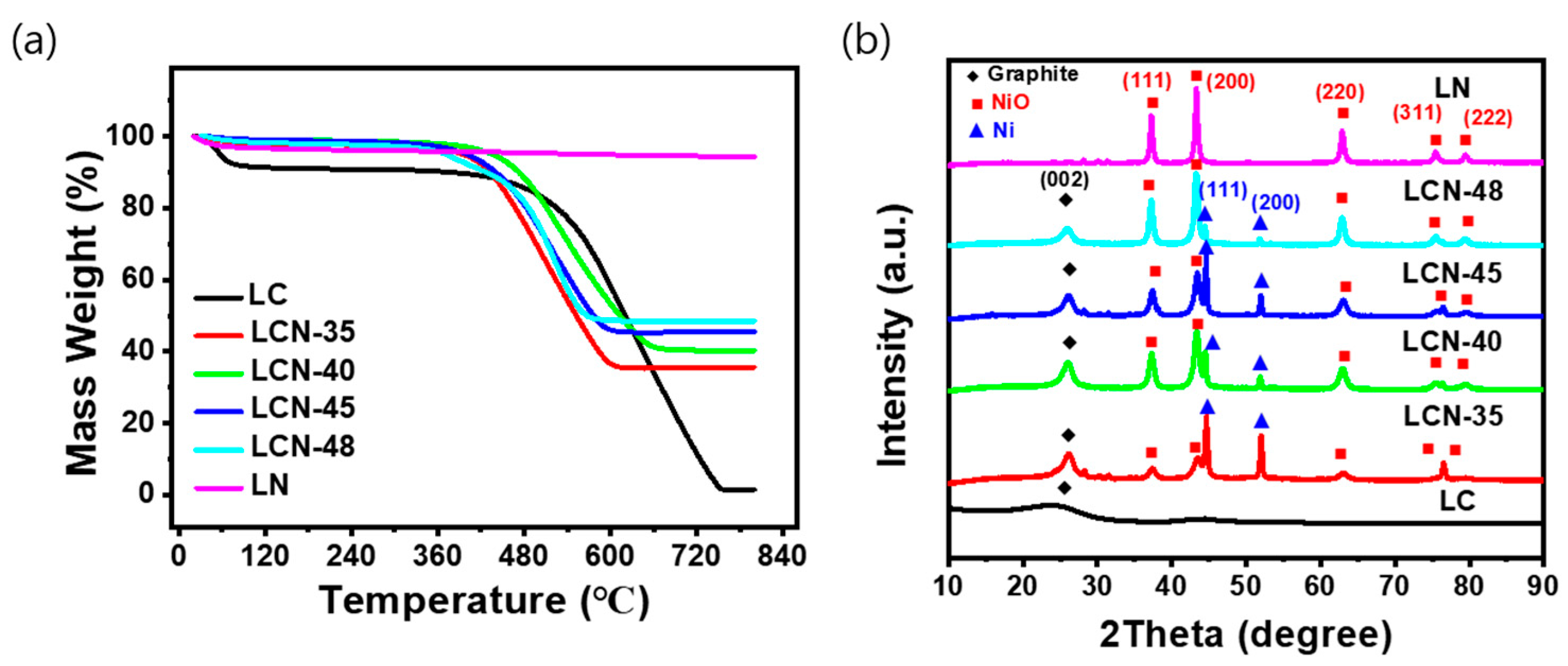
Figure 3a displays the results of the TGA analysis, which was performed to assess the thermal decomposition characteristics and NiO content of LC, LCN series, and LN samples. To investigate the changes occurring during the heat treatment process, thermal gravimetric analysis (TGA) was conducted under the condition of a constant temperature increase of 6 °C per minute in an air atmosphere using a TGA 2050 (TA Instruments) instrument, with temperatures rising up to 800 °C. The NiO content was determined by comparing the remaining mass to the initial mass, considering the reduction in carbon and moisture loss due to thermal decomposition within the measured temperature range. The contents of NiO were determined to be 0, 35.6, 40.3, 45.5, 48.6, and 94.3 wt% for LC, LCN-35, LCN-40, LCN-45, LCN-48, and LN, respectively. In the case of LC samples without NiO, the thermal decomposition behavior indicated a change due to the moisture removal from the sample between 60 °C to 100 °C. Subsequently, carbon decomposition began at 450 °C, culminating in complete carbon removal at 750 °C. In contrast, the LCN series samples exhibited a steady mass decrease from around 450 °C until approximately 600 °C, signifying carbon decomposition. No further mass change was observed above 650 °C.
Figure 3b shows the results of XRD analysis, confirming the crystalline properties of the samples. In the case of LC, the XRD pattern demonstrated an amorphous carbon, while LN, where most of the carbon had disappeared, exhibited a distinct NiO structure. For the LCN series, diffraction peaks associated with graphite and NiO were evident in all samples after undergoing three heat treatment processes. As the NiO content increased, carbon content decreased, and the peak at 26.02° corresponding to carbon gradually diminished. Notably, with the increase in NiO content from the LCN series to LN, the peaks related to NiO gradually intensified, relative to the proportion of NiO in the composite. Therefore, these XRD results confirmed the formation of a NiO-CNF composite in the LCN series samples.
The specific surface area and pore properties of the prepared samples were analyzed using Brunauer, Emmett, and Teller (BET) and Barrett, Joyner, and Halenda (BJH) measurements.
Figure S1a depict the adsorption isotherm, pore distribution, and BET plots for each sample, while
Figure S2 summarizes the data in
Table S1. The specific surface area for LC, LCN-35, LCN-40, LCN 45, LCN-48, and LN is 124.71 m
2 g
−1, 209.89 m
2 g
−1, 122.91 m
2 g
−1, 133.34 m
2 g
−1, and 205.68 m
2 g
−1, respectiviely. In the LCN series, the specific surface area equaled or exceeded that of the LC sample. This increase can be attributed to the deepening of surface curvature resulting from the heat treatment process of the sample containing the nickel source.
Figure S1a presents the adsorption isotherm curve, indicating the pore size and volume distribution within each sample. All samples, including the LC, LCN series, and LN, exhibited a sharp increase in the latter, with the isotherm line rising above 0.9, indicative of a porous structure [
24].
Figure S1b illustrates the BJH analysis results, portraying the pore size distribution graph for each sample, spanning a range of 2 to 185 nm. Overall, pore sizes exhibited non-uniformity, with various pore sizes present. LC primarily featured pores around 80 nm, the LCN series displayed an even distribution around 90 nm, and LN exhibited an even distribution around 100 nm. Mostly, it has been reported that a large specific surface area can enhance capacitance performance by facilitating electrolyte diffusion to the redox reaction’s active site. Meanwhile, it has been recently reported that specific surface area alone does not exclusively dictate a capacitance increase [
25].
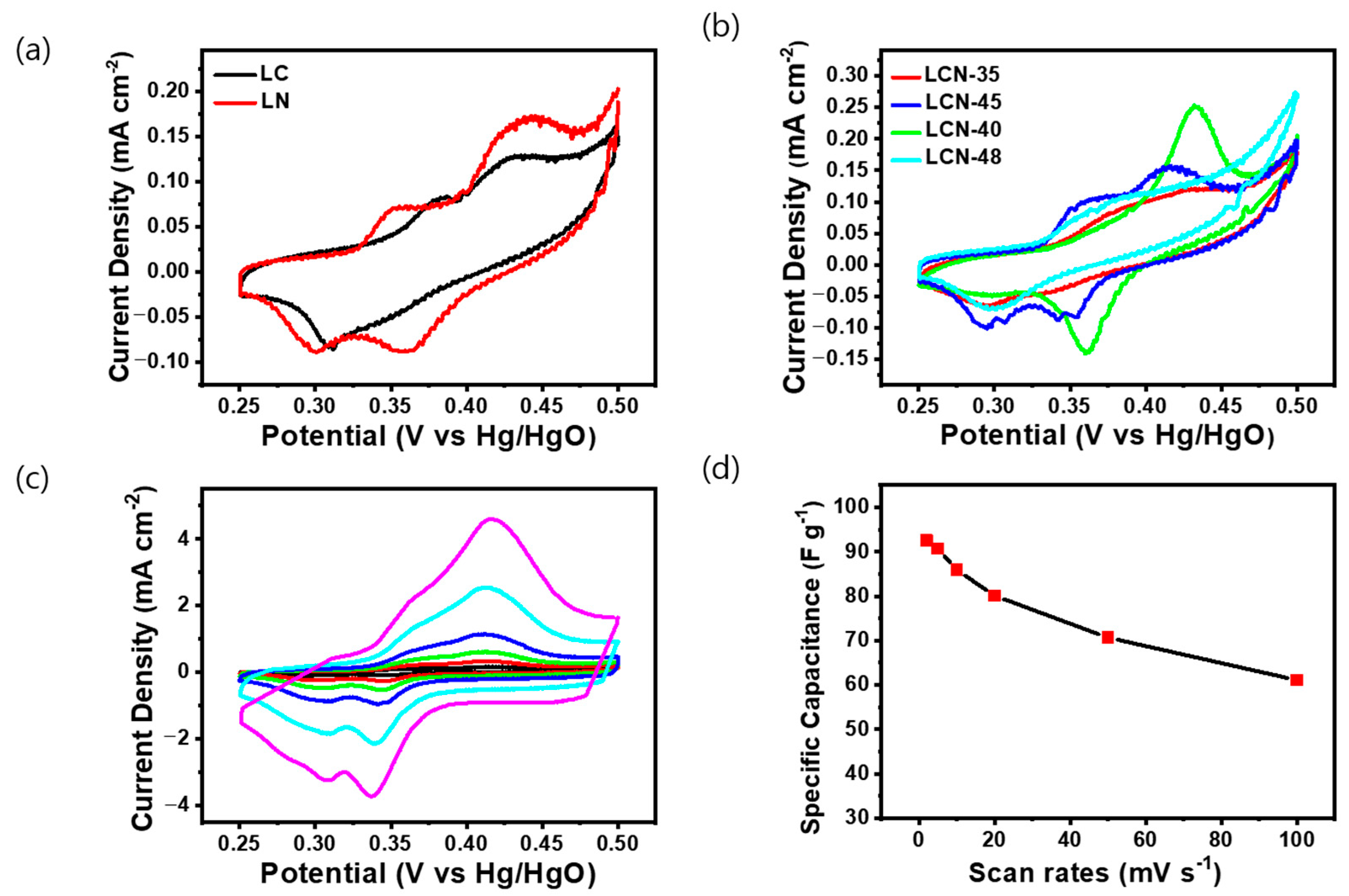
The electrochemical properties of the LC, LCN series, and LN samples, classified based on NiO content through TGA and XRD analysis, were analyzed through Cyclic Voltammetry (CV), Galvanostatic Charge/Discharge (GCD), and Electric Impedance Spectroscopy (EIS). CV was conducted using a 6 M KOH electrolyte and a three-electrode system. All electrodes were analyzed by selecting a voltage range (0.25–0.5 V) wherein oxidation/reduction reactions occur at a fixed scanning speed of 2 mV s
−1. As the curve area increased, so did the capacitance values [
26]. In
Figure 4a, the CV curve for LC exhibits a distorted rectangular shape with an unclear redox reaction, whereas the CV curve for LN displayed a distinct redox peak attributed to the reversible Faradaic transition of nickel, indicating typical pseudocapacitive behavior. In
Figure 4b, the CV curves for LCN series samples exhibited a distorted rectangular shape coupled to a distinct pseudo-capacitance behavior attributed to the Faradaic redox reaction. The reason for the different positioning of redox peaks among LCN series might be attributed to the synthetic electrochemical interference between NiO and carbon. Among the LCN series, the highest capacitance was calculated for the LCN-45 sample.
Figure 4c shows the CV curves within the voltage range of 0.25 to 0.5 V for the LCN-45 sample. CV was also used to measure chemical changes in the electrode at the scanning speed ranging from 2 to 100 mV s
−1. An increase in the scanning speed resulted in an expanded curve area, demonstrating the potential for improved charge storage capability.
Figure 4d shows specific capacitance values derived from CV conducted at various voltage scan rates for LCN-45. This highlights the charge storage mechanism of the NiO/C electrode, resulting from faradic redox reactions [
27]. The highest capacitance for the LCN-45, measured at 2 mV s
−1, reached 92.52 F g
−1 (0.18504 C g
−1), with corresponding energy and power density of 2.89 Wh kg
−1 and 46.05 W kg
−1, respectively. As the scan rate increases, capacitance decreases, with values of 90.72 F g
−1, 85.91 F g
−1, 80.09 F g
−1, 70.65 F g
−1, and 61.11 F g
−1 (0.4536 C g
−1, 0.8591 C g
−1, 1.6018 C g
−1, 3.5325 C g
−1, and 6.111 C g
−1) observed for 5 mV, 10 mV, 20 mV, 50 mV, and 100 mV, respectively. The phenomenon of pseudo-redox, which can result in the irreversibility of the redox process, is often associated with factors such as the generation of voltage polarization and ohmic resistance during the faradic redox reaction and ion diffusion limitation within the porous electrode during the redox reaction process [
28]. The electrochemical Faradaic reaction of NiO, responsible for the pseudo reaction, involves a simple adsorption/desorption reaction of OH
−. The positive peak corresponds to the oxidation of NiO to NiOOH, while the negative peak corresponds to the reverse reaction, involving the reversible conversion between Ni
2+ and Ni
3+. This redox reaction occurs on the surface of the NiO electrode and can be expressed as the following reaction (3) [
29,
30].
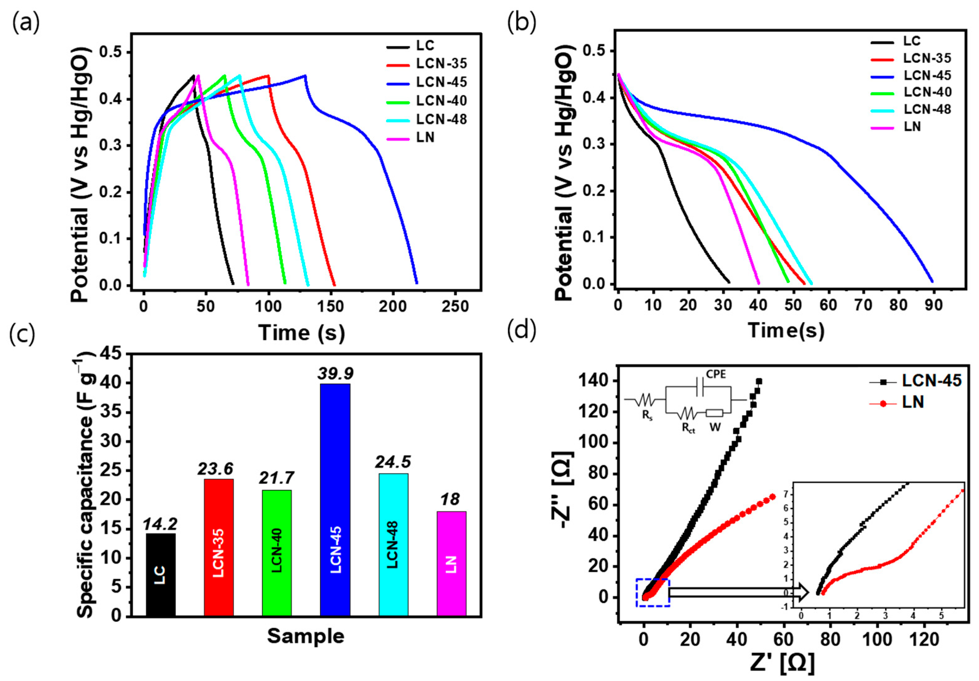
For galvanostatic charge–discharge (GCD) experiments, electrodes were prepared from each sample and the prepared electrode was employed in the three-electrode cell, with the working electrode immersed in a 6 M KOH aqueous solution.
Figure 5a shows the charge–discharge curves of the electrodes for each sample within the voltage range between 0 and 0.45 V and at a current density of 0.2 A g
−1. In the low potential range of 0 to 0.25 V, no significant Faradaic reactions, such as forming an electric double layer. However, as the current density increased, the electric double layer showed a shape close to an asymmetric triangle due to the non-Faradaic current. At the beginning of the discharge, it shows a completely asymmetric graph with a fairly large IR voltage drop. It exhibited 0.14 V, 0.16 V, 0.17 V, 0.07 V, 0.13 V, and 0.14 V for LC, LCN-35, LCN-40, LCN-45, LCN-48, and LN, respectively.
Figure 5b shows the discharge curve behavior at different current densities for each sample and shows a weight-based capacitance graph in the time potential difference curve, which is a constant current discharge curve with a voltage range of 0.45 V. In
Figure 5c, bar graphs representing the specific capacitance of each sample calculated at a fixed current density of 0.2 A g
−1 are displayed. The calculated values for LC, LCN-35, LCN-40, LCN 45, LCN-48, and LN are 14.2 F g
−1, 23.6 F g
−1, 21.7 F g
−1, 39.9 F g
−1, 24.5 F g
−1, and 18 F g
−1 (3.195 C g
−1, 5.31 C g
−1, 4.8825 C g
−1, 8.9775 C g
−1, 5.5125 C g
−1, and 4.05 C g
−1), respectively.
The impedance spectroscopy curves of LN (Bare NiO) and LCN-45 (NiO-CNFs) nanocomposites are shown in
Figure 5d. The Nyquist Plot of the LN electrode showed a highly suppressed semicircle in the high-frequency region and an oblique line in the low-frequency region, which may be due to the charge transfer process at the electrode/electrolyte interface and electrolyte ion diffusion process. At high frequencies, the arc in the curve of the LCN-45 electrode was difficult to discern, but the arc was clearly visible in the curve of the LN electrode. Through this, it can be seen that in the high-frequency range, the LN electrode has much faster charge transfer characteristics between the electrolyte and the lotus root-shaped active material, with a resistance of less than 0.2 Ω. The equivalent series resistance value of the LCN-45 electrode was found to be lower compared to the LN electrode, measuring 0.57 Ω and 0.78 Ω, respectively. This distinction arises due to the lotus root-shaped morphology and porous structure, which enhance the mobility of electrolyte ions across the electrode surface. Additionally, the LCN-45 electrode exhibits a steeper slope compared to the LN electrode, indicating a closer resemblance to an ideal electrode with a favorable electrolyte penetration pathway during the charge storage process. This suggests that the LN electrode has a lower charge transfer resistance than the LCN-45 electrode.
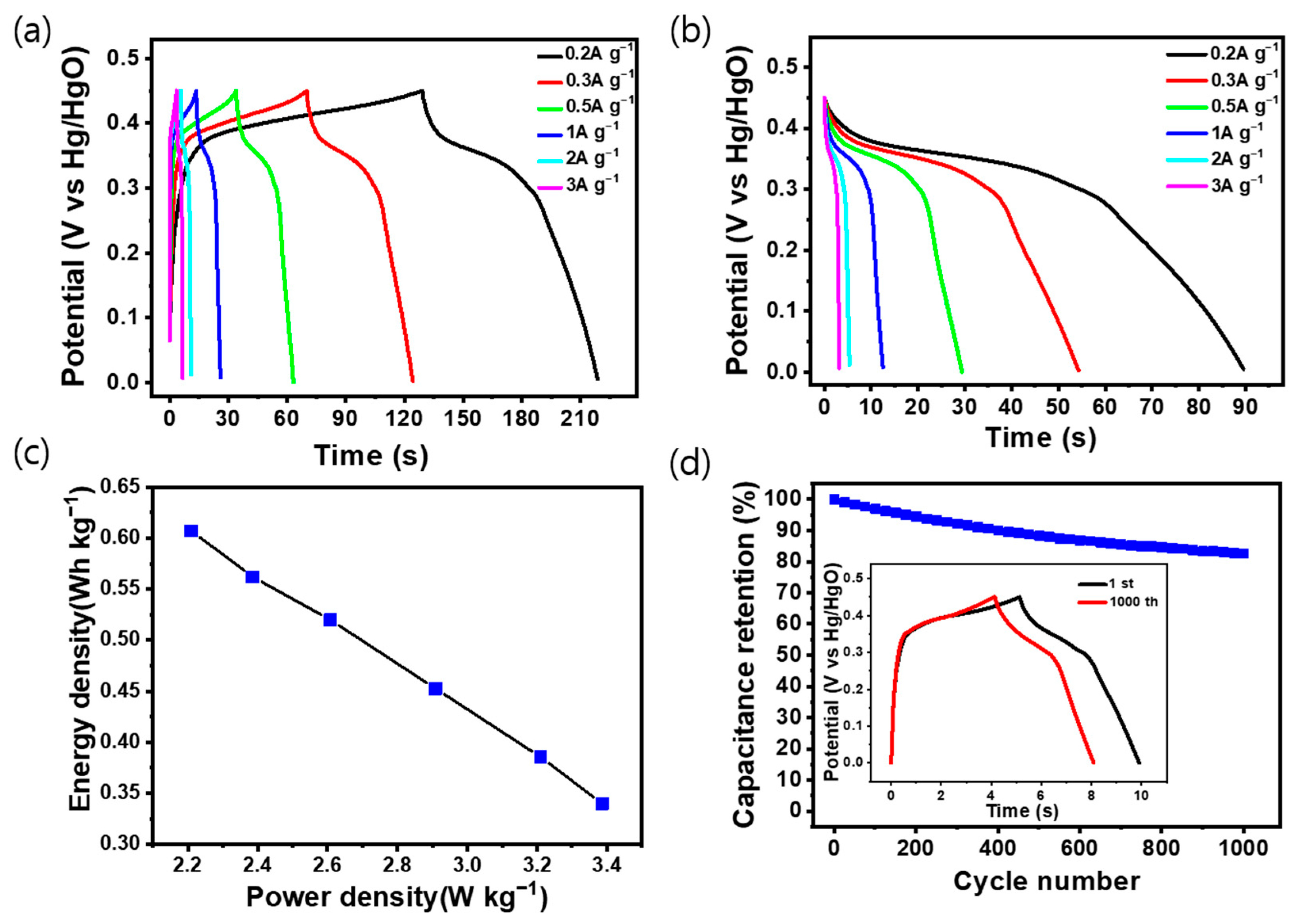
Figure 6a shows the charge/discharge curve of LCN-45 at various current density values, which shows the highest capacitance among the electrodes analyzed previously. The measurements were taken at different current densities at a potential range of 0 to 0.45 V. The graph indicates that the charge time exceeds the discharge time due to ion diffusion resistance in the electrolyte during charging and discharging, which mitigates the ion migration during charging; the other factor is the polarization of the electrode at a slow rate leading to an increase in charging time. The graph in
Figure 6b illustrates the variation in capacitance corresponding to each current density during discharge. The inserted graph in
Figure S3 displays the capacitance calculated while considering the voltage drop, with measurements conducted at current densities of 0.2, 0.3, 0.5, 1, 2, and 3 A g
−1. It was observed that the capacitance decreased as the current density increased, measuring 142.8, 138.7, 124.5, 115.3, 87.6, and 75.1 F g
−1 (32.13 C g
−1, 31.2 C g
−1, 28.01 C g
−1, 25.94 C g
−1, 19.71 C g
−1, and 16.89 C g
−1), respectively.
Figure 6c presents a Ragone plot depicting the energy and power density of the LCN-45 electrode. Cycling stability is demonstrated in
Figure 6d, where continuous charge and discharge cycles were performed on the LCN-45 electrode for 1000 cycles at a constant current density of 1 A g
−1 [
31]. The capacitance and charge/discharge time exhibited stability, with the constant current charge/discharge curve of the final cycle closely resembling the initial one. The sample’s capacitance retention rate was 82.6%. The constant current charge/discharge cycle of the LN electrode is depicted in
Figure S4, demonstrating that the hybrid-type supercapacitor maintains a high lifespan and safety even after several charge/discharge cycles.


 ,
, 