Article

Numerical Simulation Study on Deformation Mechanism of Tunnel–Landslide Orthogonal Systems and Early Warnings of Imminent Sliding

1
State Key Laboratory for Geomechanics and Deep Underground Engineering, Beijing 100083, China
2
School of Mechanics and Civil Engineering, China University of Mining and Technology, Beijing 100083, China
*
Author to whom correspondence should be addressed.
Appl. Sci. 2024, 14(7), 2790; https://doi.org/10.3390/app14072790
Submission received: 16 January 2024 / Revised: 10 February 2024 / Accepted: 28 February 2024 / Published: 27 March 2024
(This article belongs to the Special Issue Recent Research on Tunneling and Underground Engineering)

Abstract

:
This paper takes a tunnel through a landslide in Northwest China as an example, constructs a mechanical model of a tunnel–landslide orthogonal system, and explores the deformation mechanism of a tunnel–landslide system and the technology of early warnings of near-slips. Given the problem that it is difficult to accurately monitor the deformation and damage characteristics of the tunnel–landslide system using conventional methods, FLAC3D was used to analyze the deformation mechanism of the tunnel–landslide orthogonal system and numerical simulation of the NPR constant resistance large deformation anchors for the early warning of near-slips. Based on the strength reduction method, by reducing the mechanical parameters of the shear strength of the slip zone and simulating different degrees of landslides, we obtained the change rules of the displacement and the axial force of the NPR constant-resistance large deformation anchor cable in the tunnel–landslide orthogonal system, established the warning mode of the Newtonian force tunnel–landslide orthogonal system, and successfully issued a near-slip warning in actual engineering applications. The above research is of great significance to the stability monitoring and risk assessment of tunnel–landslide systems.

1. Introduction

In recent years, the construction of highways and railroads has gradually developed to the southwest and northwest, facing difficulties such as multiple high mountains and extremely complex engineering and geological conditions. According to engineering regulations, tunnel construction should avoid crossing landslides as far as possible but, in reality, the occurrence of landslides has a special, spatial, and temporal complexity, and large-scale ancient landslides are even more difficult to find during preliminary investigations and planning. Therefore, tunnel construction inevitably crosses landslides, and landslides resurrect during tunnel operation and cause tunnel damage, affecting the normal operation of the tunnel.
There have been many domestic and international research results on single aspects of landslides or tunnels, but there are fewer studies that incorporate the overall interaction of tunnel landslides. Foreign Japanese scholars Yamada Gangji and Watanabe Masayoshi [1] in “Landslides and slope failures and their prevention and control”, due to the disturbances that occur during tunnel construction slope sliding, employ a “tunnel-landslide system” for a systematic analysis, creating a preliminary summary of the tunnel–landslide system under the conditions of the formation of landslide damage phenomena and their causes. Özgür Sat Özgür Satıcı et al. [2] analyzed the mutual influence of the tunnel–landslide system in the case of ancient rock body landslides and landslides caused by heavy rainfall due to tunnel excavation and explained the interrelationships between ancient rock body landslides and tunnel excavation disturbances. Domestic scholars, such as Zhou Depei, Zhu Bitterzhu, Ma Huimin, and Tao Zhiping [3,4,5,6], through engineering, practical experience, and theoretical research, summarized a geological model of the common system of tunnel–landslide combinations, analyzed the mechanical mechanism of deformation of the tunnel–landslide system as a whole, and put forward the corresponding prevention and reinforcement measures of the tunnel–landslide system, according to different models. However, little research has been carried out on the stability monitoring of the tunnel–landslide system as a whole.
In 2016, He Manchao proposed Newton’s law of variation in forces for catastrophic changes in geologic bodies [7], constructed a mechanics model of two-body landslide catastrophes based on the measurement of Newtonian force change, explained the mechanics mode of the slope from deformation to destruction, and believed that landslide early warnings could be achieved by monitoring the change of the force on the sliding surface at the time of the occurrence of the landslide. Subsequently, He Manzhao independently developed the Newtonian force remote monitoring and early warning system, as well as the NPR constant-resistance large deformation anchor cable for the Newtonian force monitoring of landslides [8]. The Newtonian force landslide early warning model is proposed to be capable of “monitoring curve sudden rise or fall characterizes the surface cracks, large jumps characterize large cracks, small jumps characterize small cracks [9]”. The model has been successfully used for early warning in 16 landslide disaster monitoring instances. Based on the Newtonian force monitoring and warning system, Tao Zhigang and Yang Xiaojie have successfully issued early warnings of near-slips through several practical applications in engineering sites and, meanwhile, proved the scientific nature of the theory and practical feasibility through numerical simulation and mechanical analysis [10,11].
At present, there is still a lack of research on the monitoring and early warning of tunnel-crossing landslides, such a complex system of geologic hazards [12,13], and some advanced monitoring techniques can still not be linked to landslide-induced tunnel deformation and damage processes. Therefore, this paper is based on the actual project of a tunnel crossing a landslide body in Northwest China and establishes a three-dimensional numerical model of the “tunnel–landslide orthogonal system”. Based on the strength reduction method, the force and deformation characteristics of the tunnel and landslide are studied under the landslide conditions. Moreover, the tunnel–landslide orthogonal system is established to provide a reference for similar engineering disaster monitoring and early warnings.

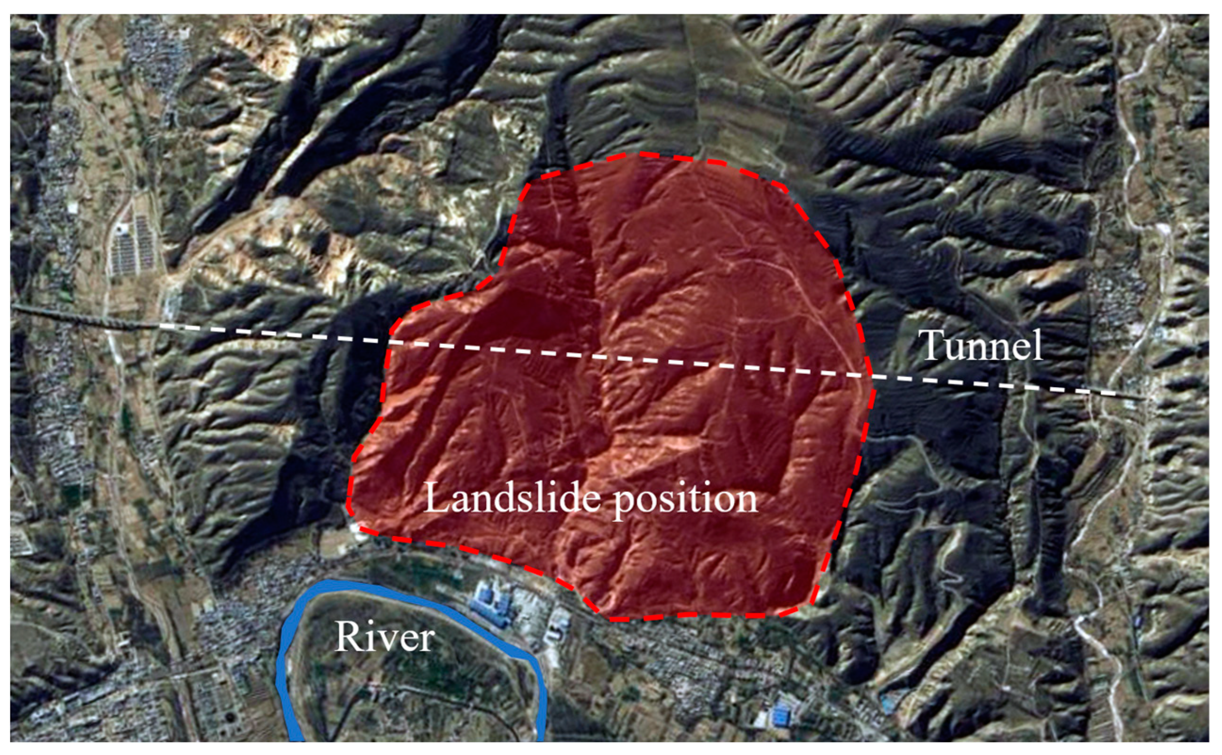
2. Analysis of Engineering Geological Conditions

2.1. Overview of the Tunnel Area

The study tunnel is located in the northwest of China, crossing high and large slopes, with relatively high terrain located within the slopes and low terrain in the parts beyond, with large topographic relief. The ground elevation ranges from 1993 to 2279 m, with a relative elevation difference of about 286 m and a natural slope of 10° to 25°. The tunnel length is 3769 m, with a maximum depth of about 290 m, and is located on the south bank of the Huangshui River. The slope in which the tunnel is located has a circle chair-shaped topography, and an overall S to N tilt, and the tunnel passes under a large ancient landslide in the NWW direction, as shown in Figure 1.

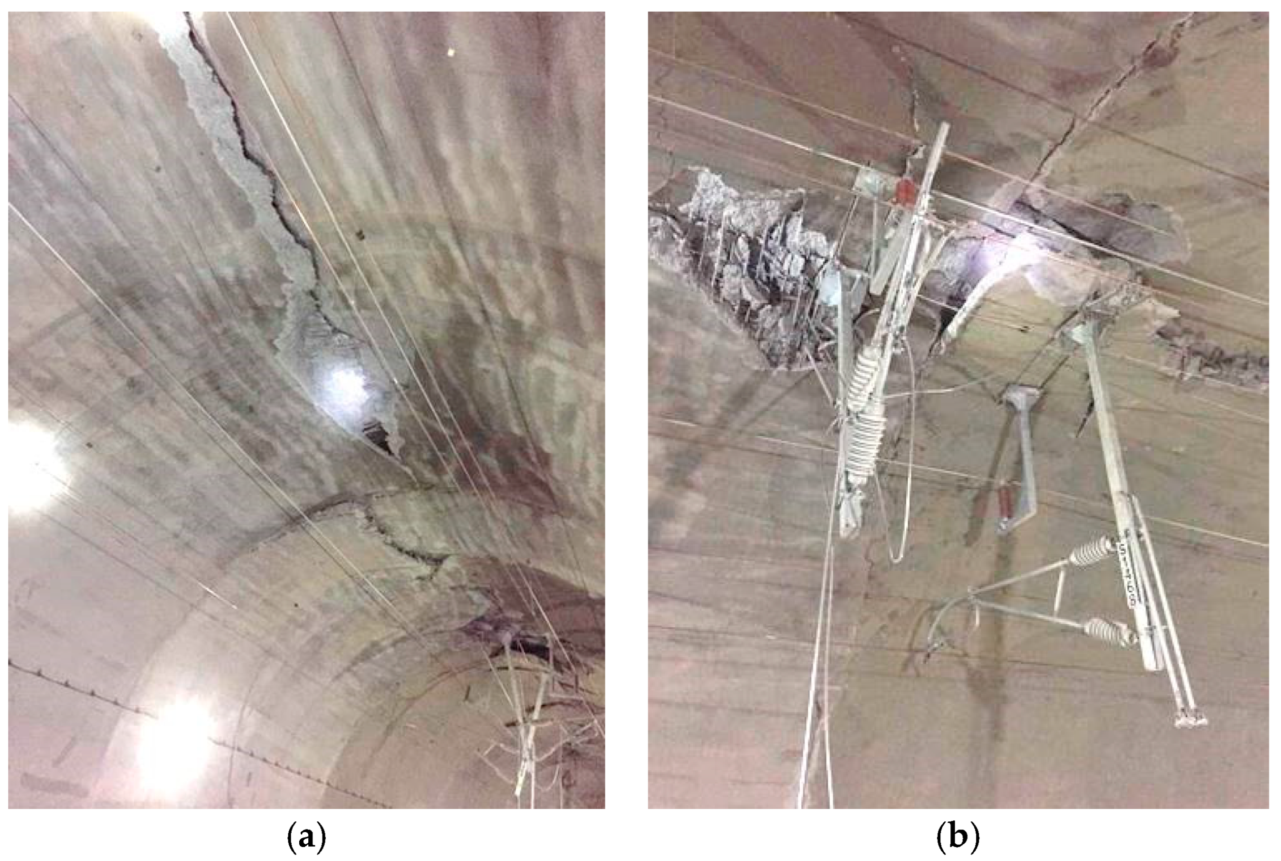
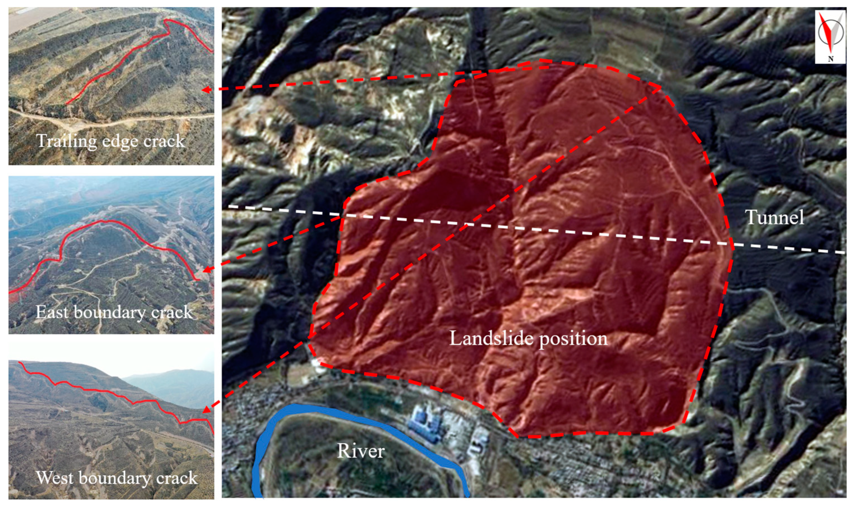
2.2. Disease Analysis

As shown in Figure 2, the tunnel crosses a large landslide body in an orthogonal direction downwards, which had a major geologic landslide disaster. The landslide body is about 1.9 km long and 1.6 km wide, with a volume of about 400 million cubic meters, a planar area of 3 square kilometers, and a sliding direction of nearly NE50°, with different degrees of cracks at the top, east, and west of the landslide body.
As shown in Figure 3, the internal deformation of the tunnel is caused by the sliding of the landslide body where the tunnel is located along the sliding surface. The main manifestations are cracks in the tunnel arch, misalignment of the second lining, cracking of the surface concrete, falling blocks, and the overall tunnel sinking, which seriously affects the safety of tunnel traffic and interrupts the tunnel operation.

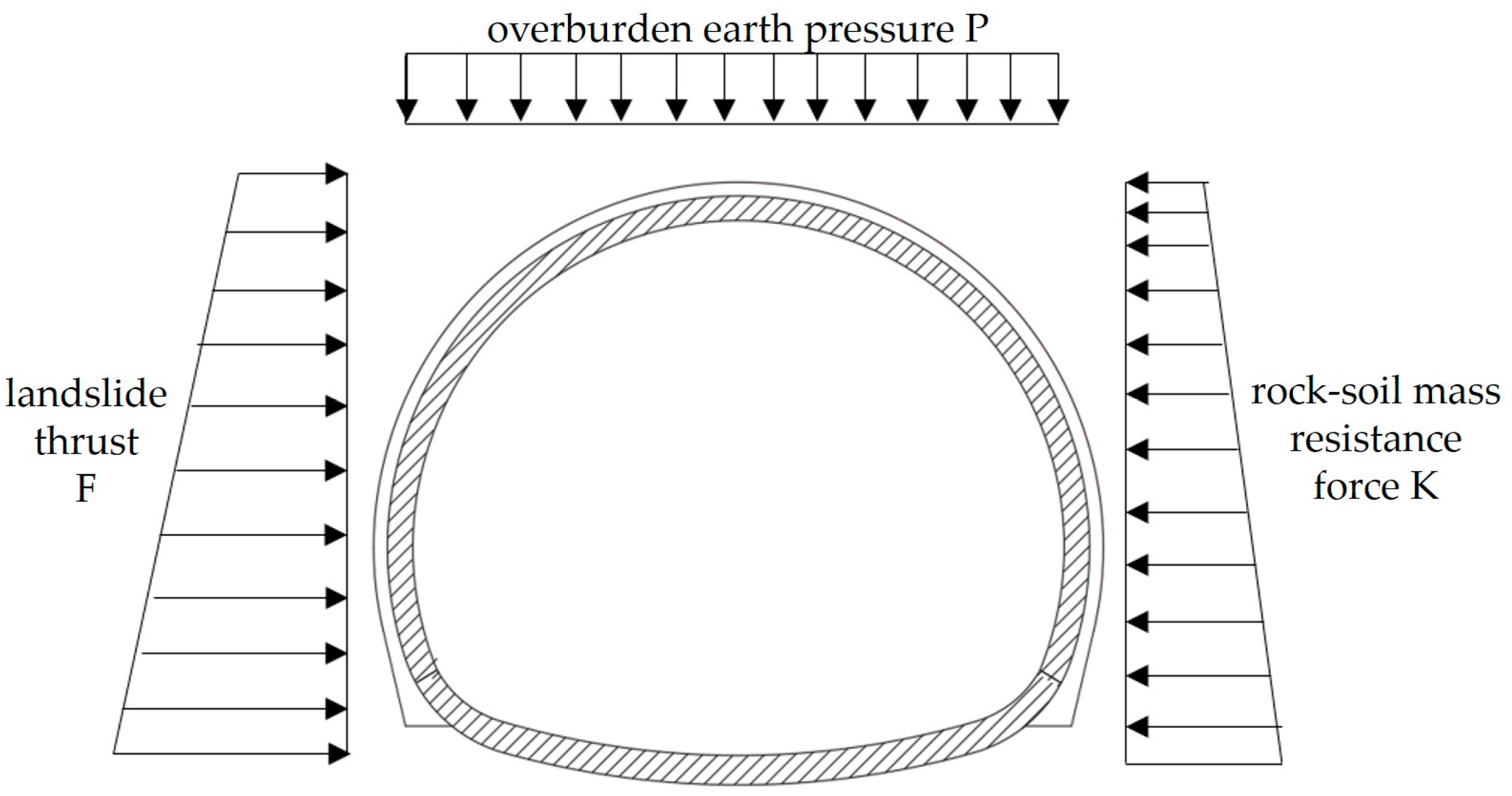
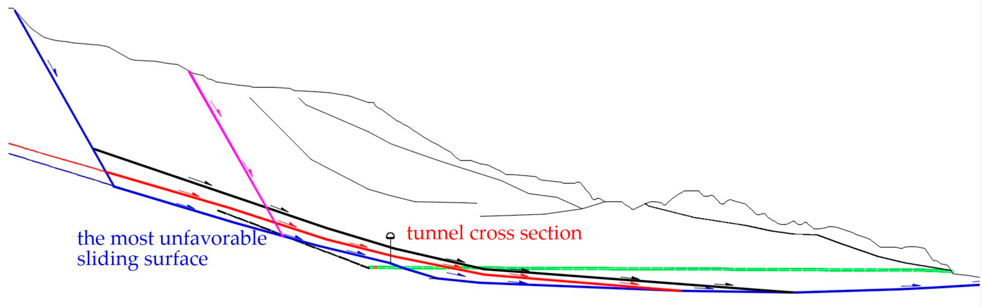
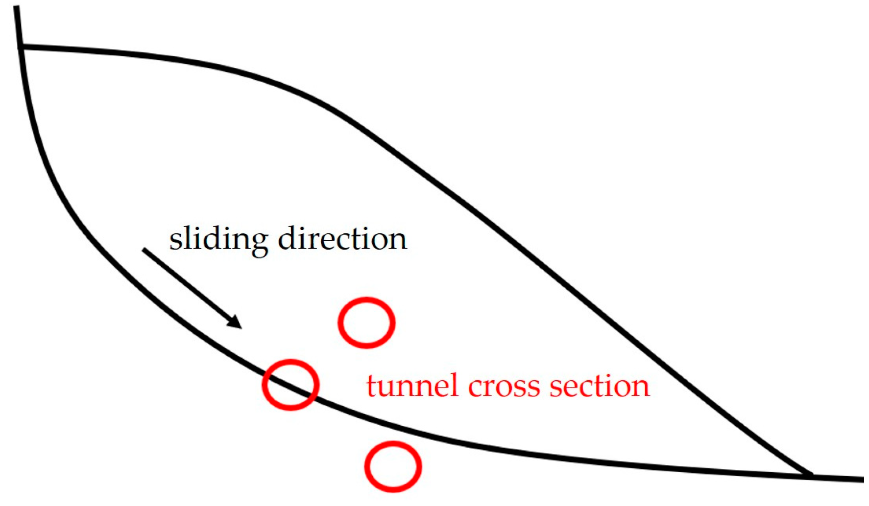
2.3. Mechanical Modeling of Tunnel–Landslide Orthogonal System

In Figure 4, the engineering geological section of the deep geological hazard where the tunnel crosses the landslide body in an orthogonal direction is shown. Judging from the core identification of the investigation borehole and the deployment of the deep hole displacement monitoring curve, there exists a deep creep surface, i.e., the most unfavorable sliding surface, which is located about 50 m below the tunnel on the II-II’ engineering geological section.
According to the angle between the sliding direction of the landslide and the longitudinal axis of the tunnel, the tunnel–landslide system can be divided into three main forms [14]: the angle of 70~90° is the orthogonal system, the angle of 20~70° is the oblique system, and the angle of 0~20° is the parallel system. The angle between the axis direction of a tunnel in the northwest and the main sliding direction of the upper landslide is approximately vertical, and the angle is 70~90°. Therefore, it is approximately identified as the tunnel–landslide orthogonal system for subsequent analysis.
From the plane, the tunnel–landslide orthogonal system can be divided into two forms: the tunnel passes through the interior of the landslide body and the tunnel is located outside of the landslide body (Figure 5). When passing through the landslide body, there are also cases where the tunnel is located in different positions relative to the sliding surface in the geological section. When the landslide body is a single sliding surface, according to the relative position of the tunnel, it can be divided into three cases: the tunnel is located inside the landslide body (a), the tunnel intersects with the sliding surface (b), and the tunnel is located below the sliding surface (c) (Figure 6). The force and deformation of the tunnel–landslide system are different at different spatial locations [15,16], and according to the planar and spatial locations of the tunnel–landslide system studied in this paper, it is determined to be the tunnel–landslide orthogonal system with the tunnel located inside the landslide under the condition of a single sliding surface, and all the research herein will be carried out based on the system in the following sections.
When the tunnel crosses the landslide body, the external forces acting on the tunnel are the overlying geotechnical body pressure P when the landslide is not formed, the downward sliding thrust F after the formation of the landslide, and the geotechnical body resistance K. The geotechnical body pressure P is measured by on-site measurements or by other methods, and the downward sliding force F can be determined by numerical methods or by the limit equilibrium method, as shown in Figure 7.
When the tunnel as a whole is located inside the landslide, the tunnel can be approximated as a thin-shell hollow ground beam for analysis [17]. The top of the tunnel arch and the shoulders of the two side arches are affected by the sliding force of the landslide, while the bottom elevated arch and the bottom of the two arches are affected by the resistance of the rock and soil body or the residual sliding force of the landslide. The tunnel as a whole can be analyzed as a large deflection beam structure; the internal thrust of the landslide body is generally larger than that of the top and bottom, and thus the force on the arch top and arch shoulder in the middle of the tunnel is larger than that on the two sides, and the bending moment is also larger. Therefore, when a landslide disaster occurs, the tunnel will undergo bending deformation, with through cracks on the tunnel arch and transverse and longitudinal cracks on the side walls, as well as overall slippage with the entire landslide body.
When the tunnel passes through a landslide body and there is a portion of the tunnel outside the landslide body, the tunnel model can be approximated as a simply supported beam structure for mechanical analysis [17], as shown in Figure 8. The portion of the tunnel structure outside the landslide will be subjected to large shear stresses under landslide action, and the portion inside the landslide will be subjected to large bending moments. Under this condition, circular cracks will appear at the tunnel end tangent to the landslide, and in severe cases, even transverse shear faults in the direction of landslide movement will occur. Similarly, the central tunnel vault and the two side arch shoulders are affected by the landslide sliding force. Under the action of the landslide sliding force, the side of the tunnel close to the sliding direction of the landslide body will be subject to different degrees of tensile deformation, longitudinal bending may occur, and transverse penetrating cracks will appear in the vault and the side walls.

3. Numerical Simulation Analysis of Deformation Mechanism of Tunnel–Landslide Orthogonal System

3.1. Numerical Model and Boundary Condition Selection

According to the geological characteristics of the landslide in a tunnel in northwest China and the positional relationship with the tunnel, the stratigraphic division was carried out by the actual geological situation of the slope, which was mainly divided into four parts: the tunnel, the slide body, the slide zone, and the slide bed. At the same time, the stratigraphic boundary optimization was carried out based on the original slope section to facilitate the subsequent numerical simulation calculation. As shown in Figure 9, for the simplified stratification of the landslide section in the process of numerical modeling, separate stratification was carried out at the slip belt according to the location of the sliding surface of the main axial section of the II-II’ landslide.

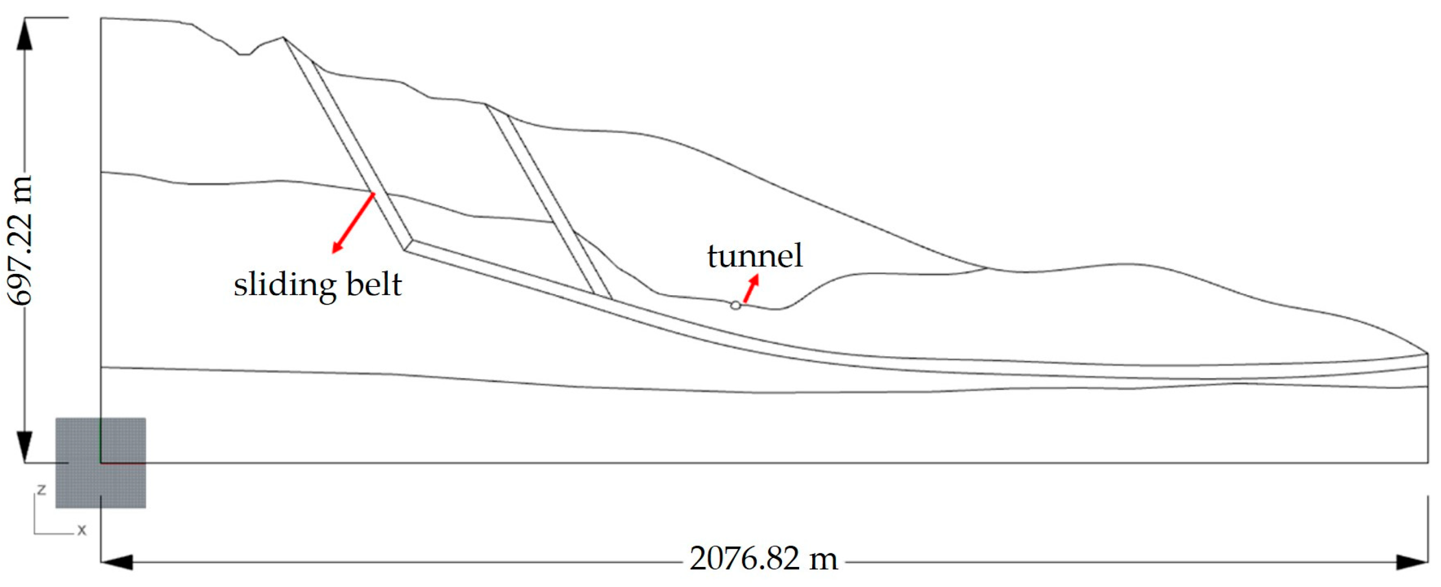
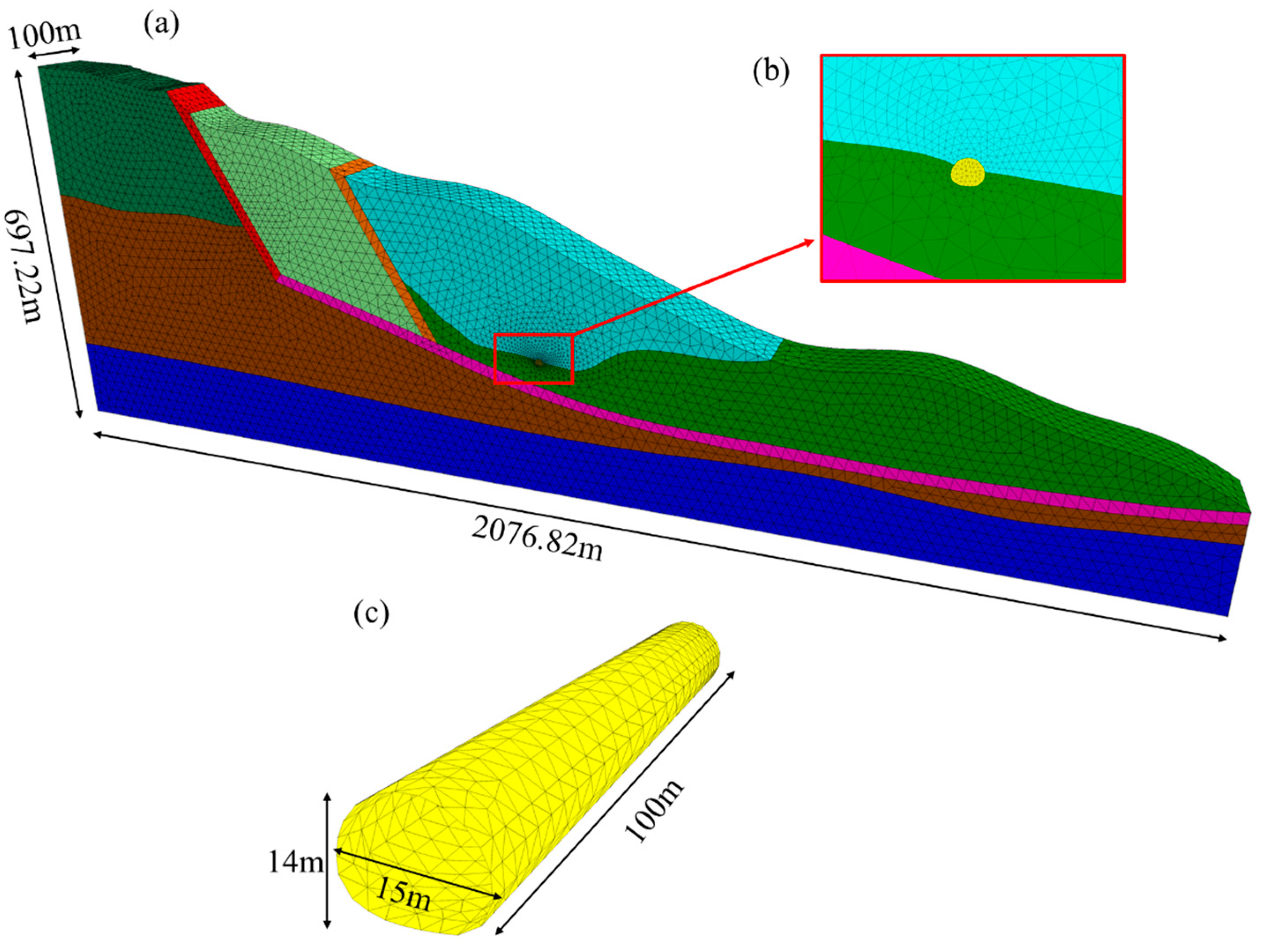
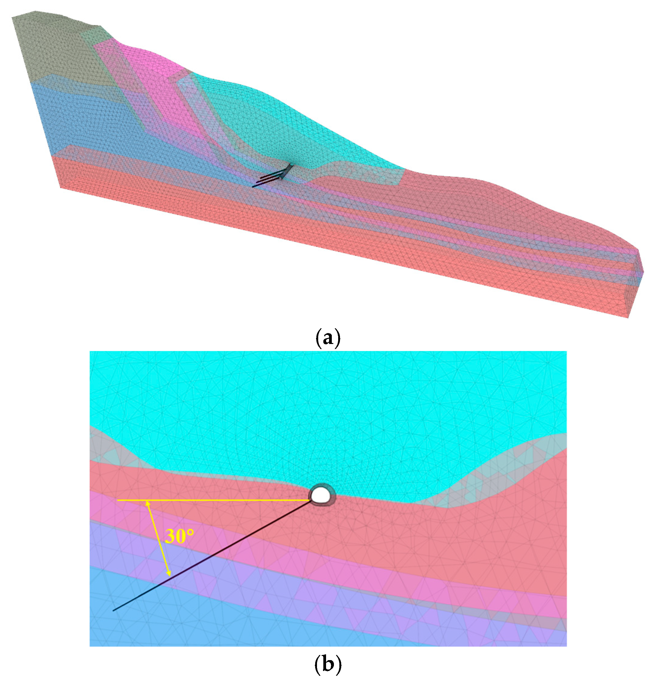
3.2. Solid Modeling of Tunnel–Landslide Orthogonal System

According to the actual engineering situation, the model materials in the orthogonal system of a tunnel-slide in northwest China are mainly divided into the tunnel, common geotechnical body, slide body, slide zone, bedrock (landslide bed), and other parts. Among them, the distribution of soil layers in the tunnel peripheral rock and slip belt is mainly mudstone sandstone and sandstone conglomerate, and the overlying soil layer is loess. The mechanical parameters and properties of different strata are assigned according to the different properties of each layered material. Specific numerical simulation calculation parameters are based on the field engineering geological investigation report and indoor test results and combined with relevant engineering specifications and similar engineering experience, as shown in Table 1 below.
The numerical model is established according to the main axis section of the tunnel–landslide system II-II’, and the geometry is the same as the original section. The model is mainly divided into four parts: slide bed, slide body, slide belt, and tunnel. The total length of the model is about 2076.82 m, and a thickness of 100 m is taken as the research object. The shape of the tunnel is a horseshoe, with a width of about 15 m and a height of about 14 m, as shown in Figure 10. The model meshing is performed by the Griddle module in Rhino 6 software, and the model is divided by tetrahedral mesh. The number of cells in the tunnel–landslide system model is 25,825 and the number of nodes is 51,538; the number of cells in the tunnel model is 5258 and the number of nodes is 1314. The tunnel and the grid around the tunnel are encrypted locally in the model, which can better reflect the deformation and damage of the tunnel with the sliding of the landslide body.

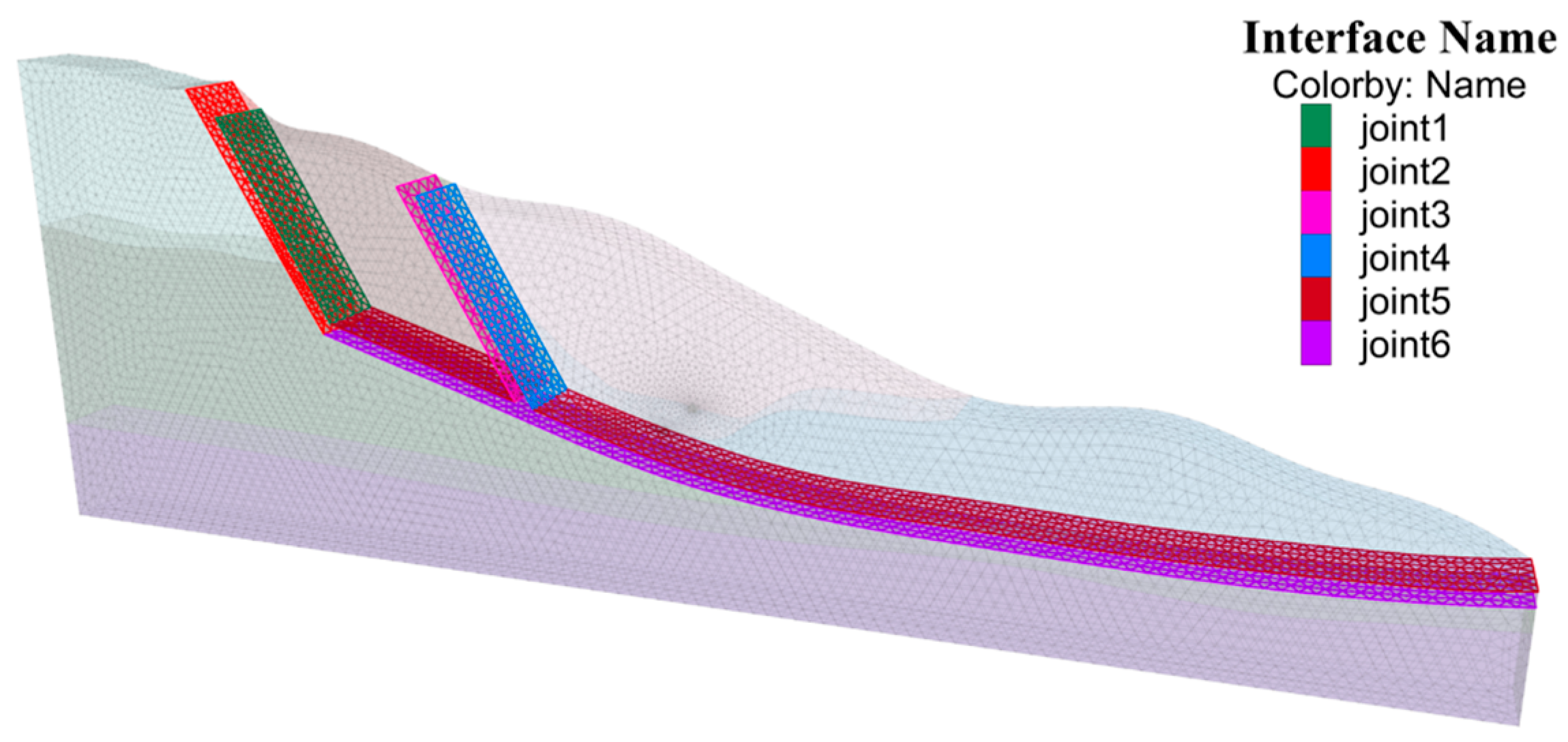
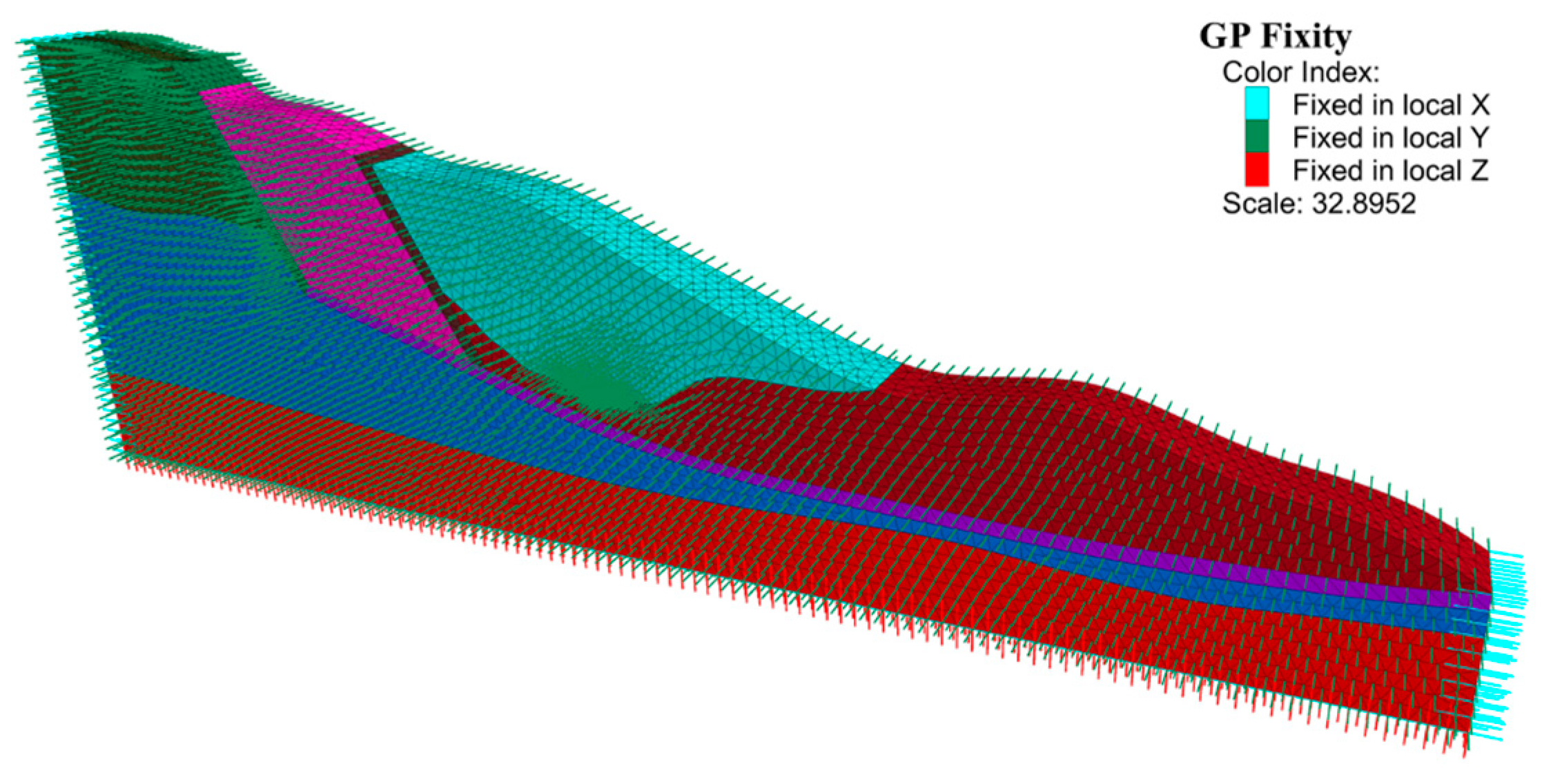
3.3. Establishment of Model Contact Surfaces and Constraints

Considering the large differences in soil material properties and physico-mechanical parameters between the computational model slide, slide belt, and slide bed, this will have a large impact on the results of slide displacement [18]. Therefore, in FLAC3D version 6.0, by setting up contact surfaces between different strata, joint surfaces, faults, etc., the effect of errors due to large differences in stiffness is reduced. At the same time, it can also better reflect the shear-slip damage characteristics between the contact surfaces. In this model, contact surfaces are set up on the lower surface of three slide belts, with a total of six to reflect the deformation and damage characteristics of the upper slide body, as shown in Figure 11.
This calculation model sets the displacement constraints in each direction, and the initial displacement is set to zero on the front, back, left, and right surfaces of the model as well as the bottom surface of the model, respectively. There are five artificial intercept boundaries in this model, in which the bottom of the model fixes the z-axis displacements of all nodes in the plane, the left and right sides fix the x-axis displacements of the model, the front and rear surfaces fix the y-axis displacements of the model, and the top of the model does not set the constraints, as shown in Figure 12.

3.4. Numerical Simulation Program Design

There are many factors affecting the occurrence of landslides in actual engineering conditions, mainly due to the weakening of the shear strength index of the slope geotechnical body as a result of natural weathering, rainfall scouring, seismic vibration, etc. [19]. The strength reduction method in FLAC3D focuses on the analysis of the results of the change in stress–strain in the destructive process of the geotechnical body during the computation process, rather than the process of the reasons that lead to changes in stress–strain [20]. Therefore, in this study, the influence of rainfall, groundwater, and earthquakes is not considered, but the shear strength index of the slope geotechnical body is directly discounted. The values of shear strength index c and φ of the slope geotechnical body are simultaneously divided by the folding multiplier, i.e., the folding coefficient F s , to obtain the folded shear strength index c and φ . Then, c , φ as the new shear strength index is brought into the FLAC3D programming language to re-test the calculation when the slope soil body meets the stability determination conditions. F s can be called the minimum stability coefficient of the slope.
F s = c c ,   F s = tan φ tan φ
where c is the cohesion of the original slope geotechnical body; c is the cohesion of the discounted slope geotechnical body; φ is the internal friction angle of the original slope geotechnical body; and φ is the internal friction angle of the discounted slope geotechnical body.
This paper adopts the strength reduction method and combines the FLAC3D 6.0 software to calculate the stability of engineering examples and takes the following three points as the judgment of slope stability: whether the static equilibrium calculation is convergent, the displacement of the sudden change in the characteristic point, and the penetration of the plastic zone of the slope, and combines the three points of judgment to comprehensively judge the overall stability of the slope.
This tunnel is an existing tunnel; to study the force and deformation characteristics of the tunnel under the action of upper landslide thrust in the tunnel–landslide system and the change in axial force of NPR constant-resistance large deformation anchors, the strength reduction method is used to reduce the shear strength parameter of rock and soil bodies in the slip zone. By reducing the angle of internal friction and cohesion, the landslide thrust is simulated to be generated by the landslide body sliding under the water softening and an earthquake occurring. Comparative analysis was carried out using the original scheme (without discounting) and four different discounting schemes, which are shown in Table 2, Table 3 and Table 4 below.
Plan 1 is the original plan, where the friction angle and cohesion in the slide belt take the actual value according to Table 2, Table 3 and Table 4, and Plan 2 to Plan 5 take different discount coefficients to discount the friction angle and cohesion in the slide belt to increase the landslide downward force and compare and analyze this with the original plan.

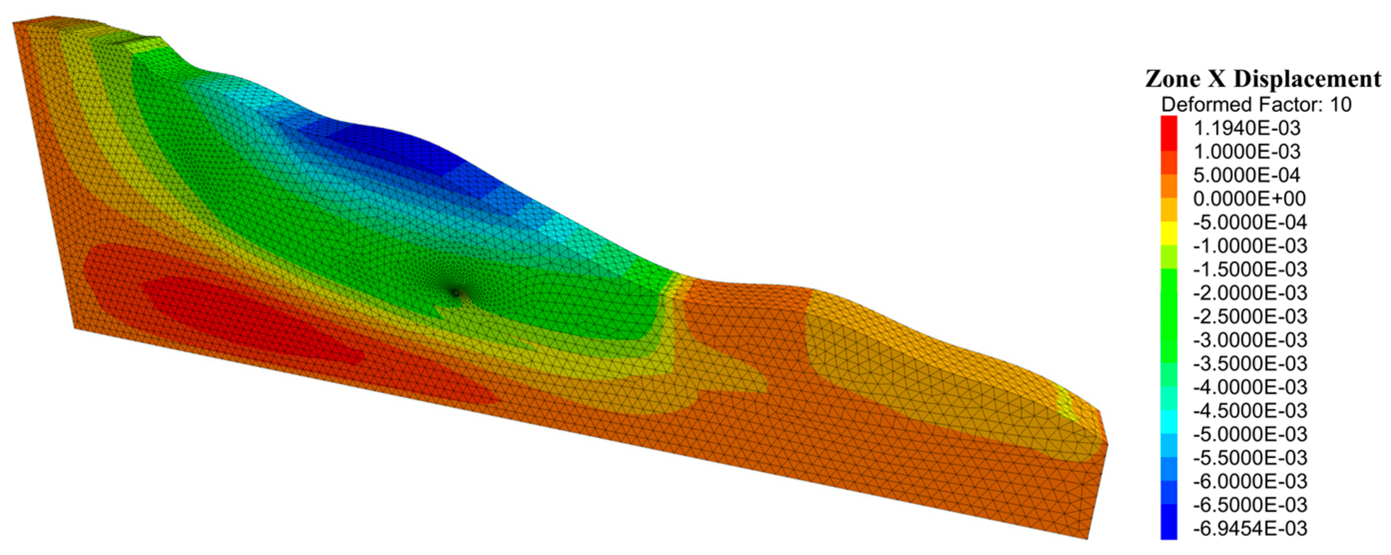
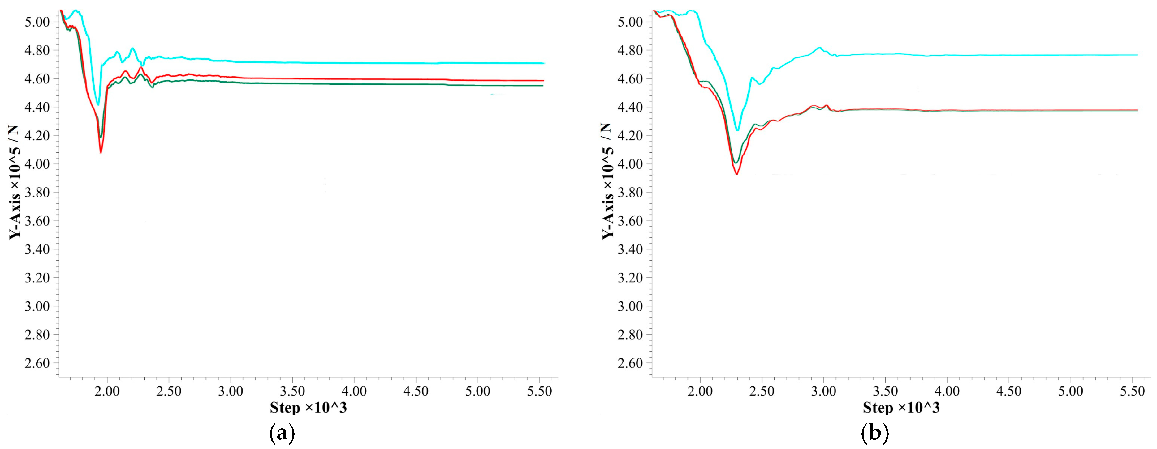
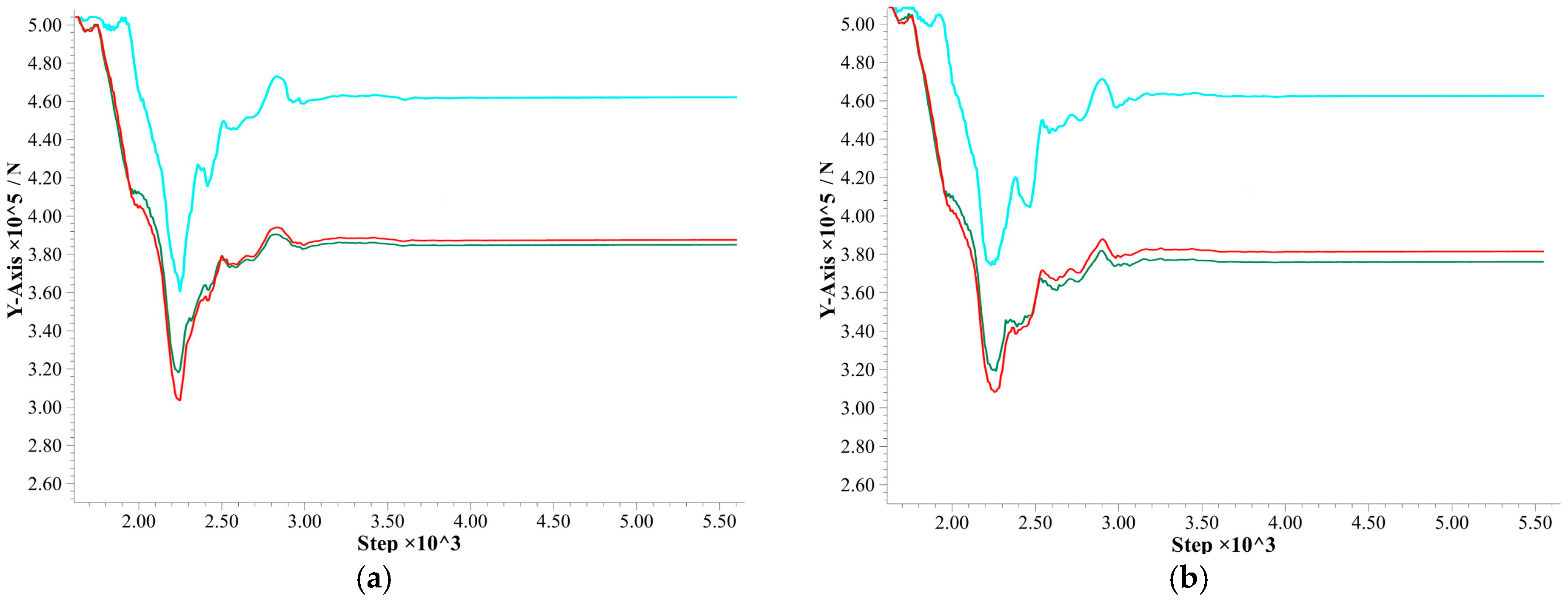
3.5. Stability Analysis under Original Plan Conditions

After the tunnel excavation was completed, the horizontal displacement at the lower slip zone of the tunnel was relatively large, and the overall slide body on the upper slip zone showed a certain amount of displacement, ranging from 1.5 × 10 3   m to 6.95 × 10 3   m . The rock body located on the top of the slide body had the largest amount of displacement, which amounted to 6.95 × 10 3   m , and the absolute value of the overall horizontal displacement of the side slopes was relatively small, as shown in Figure 13.
Combined with the vector map of tunnel displacement after tunnel excavation in Figure 14 and the analysis of monitoring displacement curves at characteristic points of the tunnel lining structure in Figure 15, it can be seen that the tunnel was affected by the landslide in which it was located, and a settlement ranging from 6 mm to 14 mm was generated. The greatest deformation was observed at the top of the arch and the left arch shoulder, with a deformation of 9.43 × 10 3   m , which was consistent with the direction of the downward force generated by the landslide. At this stage, the mechanical parameters of the geotechnical body did not change, and the orthogonal system of the tunnel and landslide remained relatively stable without any damage.

3.6. Stability Analysis under Different Reduction Conditions

(1)
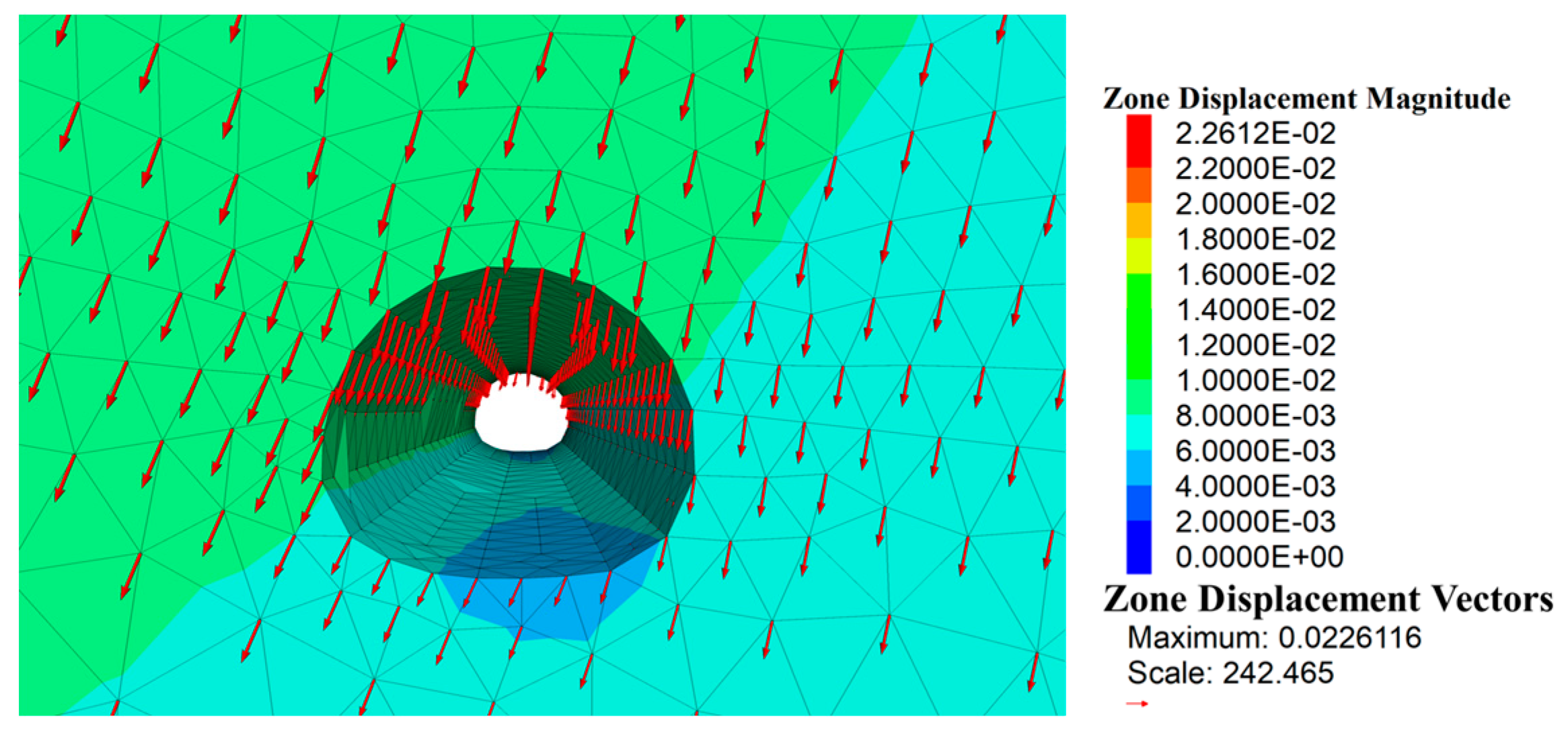
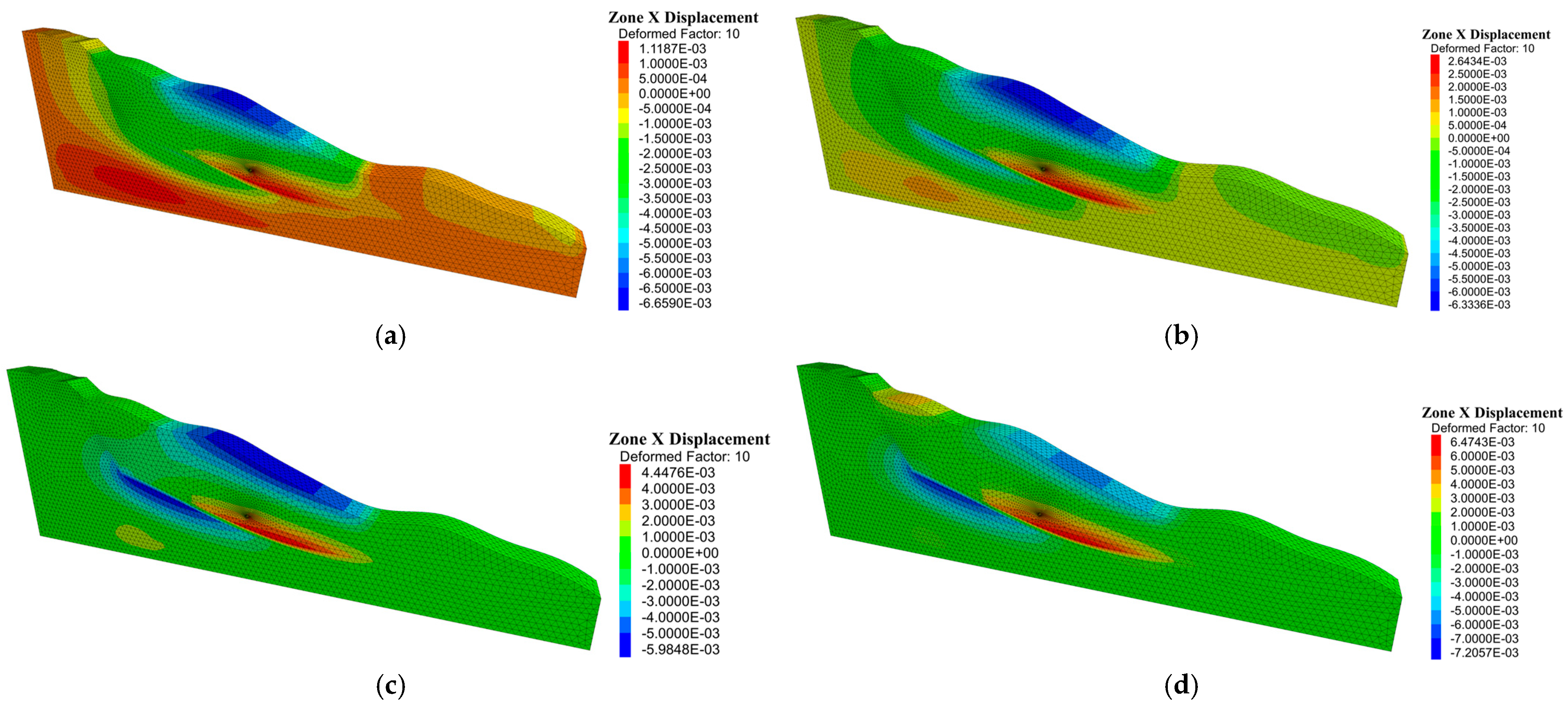
Displacement analysis
Comparing the horizontal displacement cloud diagrams of the slope under the conditions of different folding coefficients, with the increase in folding coefficients, the geotechnical parameters of cohesion c and angle of internal friction φ of the slide zone gradually decrease, and larger displacements are gradually generated at the top of the slope and the slide zone. As shown in Figure 16, the horizontal displacement of the slide body gradually moves from the upper geotechnical body to the negative direction of the x-axis under the action of compressive stress and develops to the positive direction of the x-axis, which gradually generates the landslide.
Comparison of the settlement monitoring curves of the tunnel lining structure under different discount factor conditions. As shown in Figure 17, with the increase in the reduction factor, the cohesive force c and the angle of internal friction φ decrease, and the tunnel located in the landslide body generates a certain amount of horizontal and vertical displacement under the action of landslide thrust, and the amount of settlement gradually increases from 9 mm to 3.2 cm. With the increase in the landslide thrust, the overall structure of the tunnel will be damaged, and the overall stability will be reduced, which will affect the normal operation of the existing tunnel.
(2)
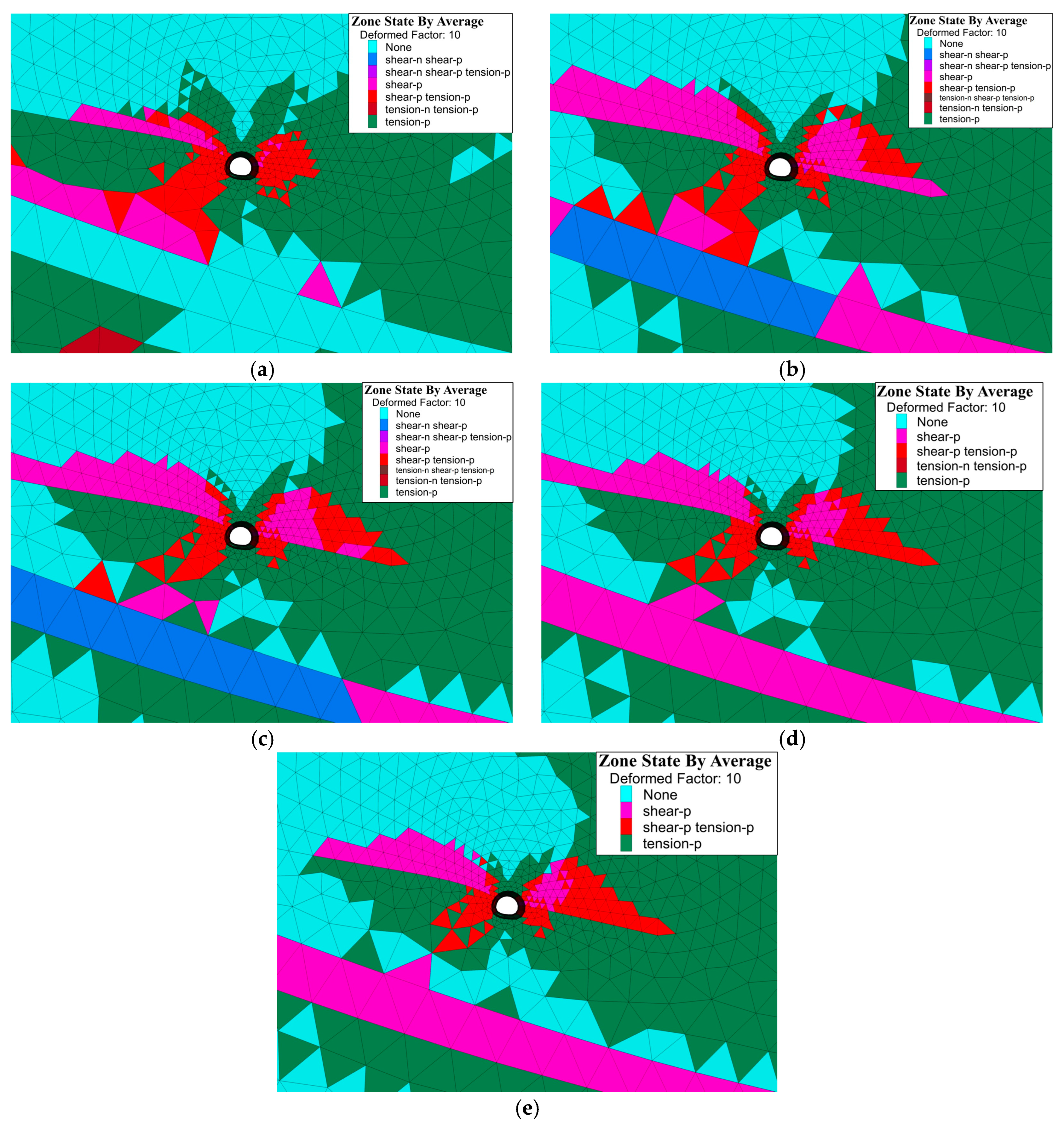
Plastic-zone analysis
In Scenario 1, the tunnel–landslide system as a whole presents a stable state. The tunnel structure is subjected to the self-gravity stress of the upper geotechnical body and the distribution of the plastic zone is characterized by tensile stress at the top and bottom and shear stress at the left and right sides. However, the distribution of the plastic zone has entered the yield state and has withdrawn and reached the stable state.
Comparing the distribution of the plastic zone of the geotechnical body around the tunnel under different discount factor conditions, the stability of the geotechnical body in the slip zone decreases with the increase in the discount factor, and it is gradually in a state of destruction. In Figure 18b,c, it is shown as shear-n; at this time, the geotechnical body at the slip zone is in a state of shear damage. With the gradual increase in the landslide thrust acting on the left side of the tunnel, the distribution of the tensile zone at the top and bottom of the tunnel gradually decreases, and the distribution of the shear zone on the left and right sides gradually increases. The geotechnical body at the slip zone finally enters the yielding state and has withdrawn and stabilized, which is expressed as shear-p, indicating to a certain extent that the cohesion c and the angle of internal friction φ at this time are the critical values for the occurrence of landslides.

4. Numerical Simulation Analysis of NPR Constant-Resistance Large Deformation Anchor Cable for Early Warning of Slip Criticality

4.1. Establishment of the Model

The NPR constant-resistance large deformation monitoring anchor cable was applied at the left elevated arch inside the tunnel. As shown in Figure 19a, the length of the anchor cable is 120 m, and the length of the anchoring section is 15 m, which penetrates the slip belt into the slip bed and anchors in the bedrock. As shown in Figure 19b, the angle of incidence of the anchor cable is 30° from the horizontal and each anchor cable is spaced 30 m longitudinally, with a total of three setups.

4.2. NPR Constant-Resistance Large Deformation Anchor Cable Constitutive Model Construction

Compared with ordinary PR (Poisson’s Ratio) anchor cables, NPR (Negative Poisson’s Ratio) constant-resistance large deformation anchor cables can adapt to large deformation of the surrounding rock and provide effective high constant resistance [21]. NPR anchor cables belong to an elastic–plastic body, and a one-dimensional eigenstructure model is used in Flac3D to redefine the characteristics of the anchor cables’ units, including the geometry, the material parameters, and the anchoring agent, using the Fish language. The deformation of the NPR constant-resistance large deformation anchor cable was set in the one-dimensional intrinsic model to not exceed the tensile yield strength and compressive strength.
The prestress design value of the NPR constant-resistance large deformation monitoring anchor cable is 60 t, and 600 kN prestress is applied in FLAC3D. After the prestressing force is applied, the slope soil is squeezed and undergoes a certain creep deformation, and the NPR constant-resistance large deformation monitoring anchor cable produces a certain degree of relaxation, and the final axial force value is less than the set constant-resistance value after stabilization. As shown in Figure 20, the initial actual axial force value of the NPR constant-resistance large deformation monitoring anchor cable after the initial prestress setting in FLAC3D is about 500~510 kN.

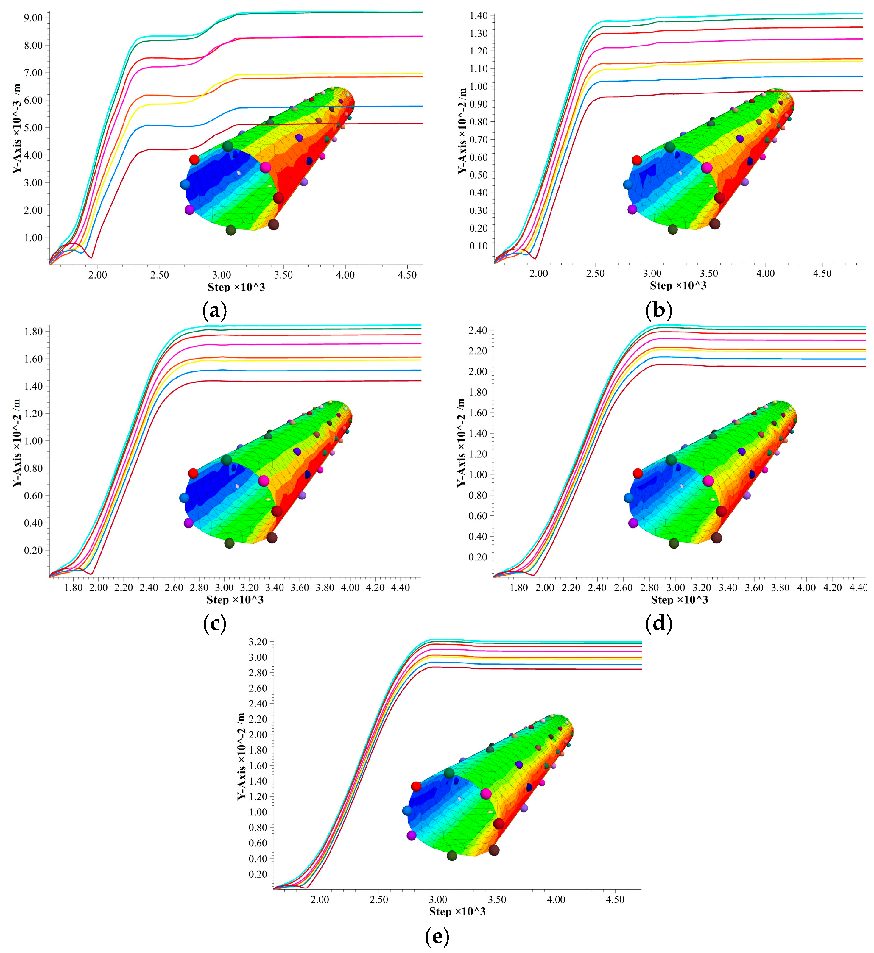
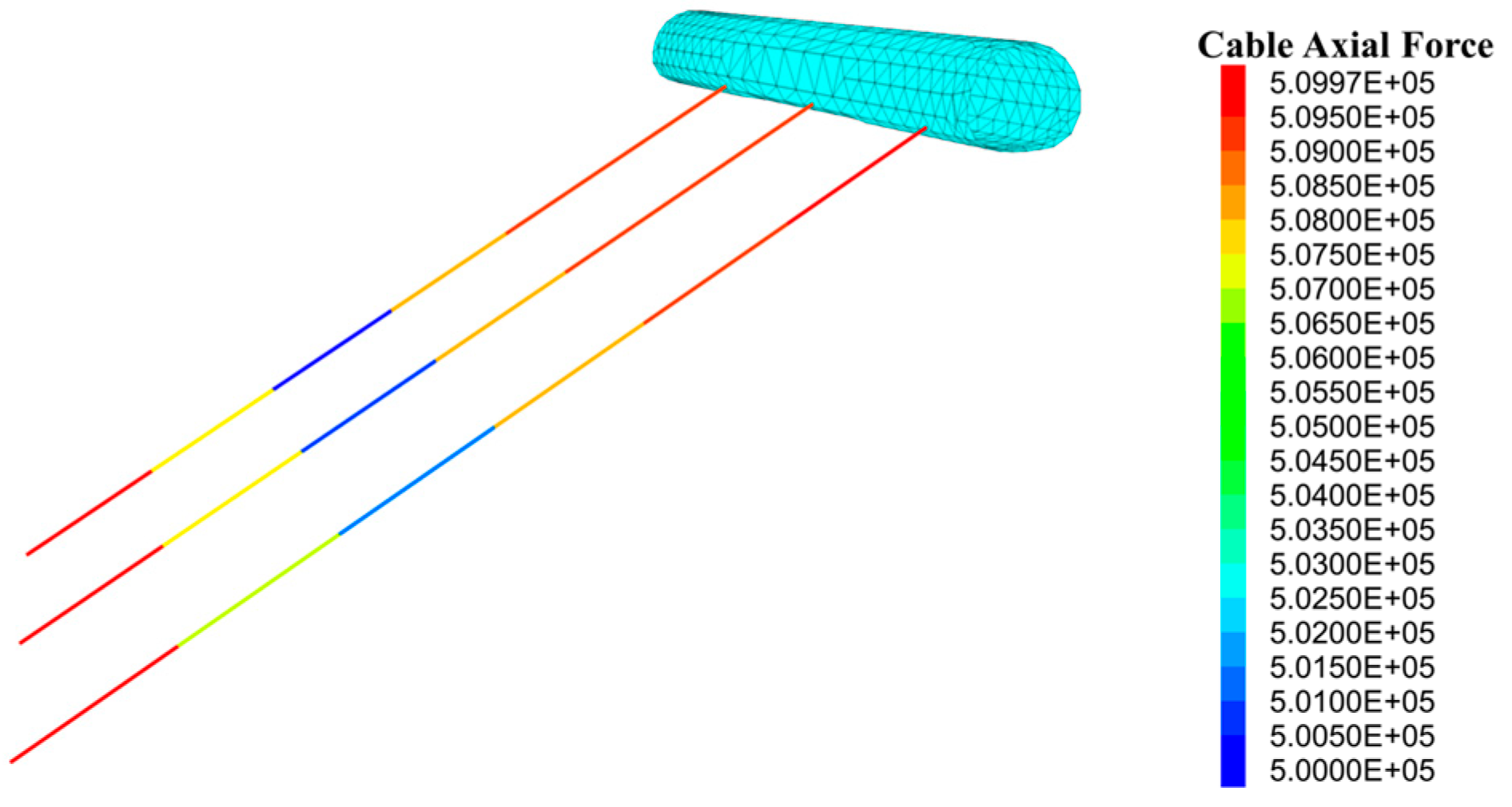
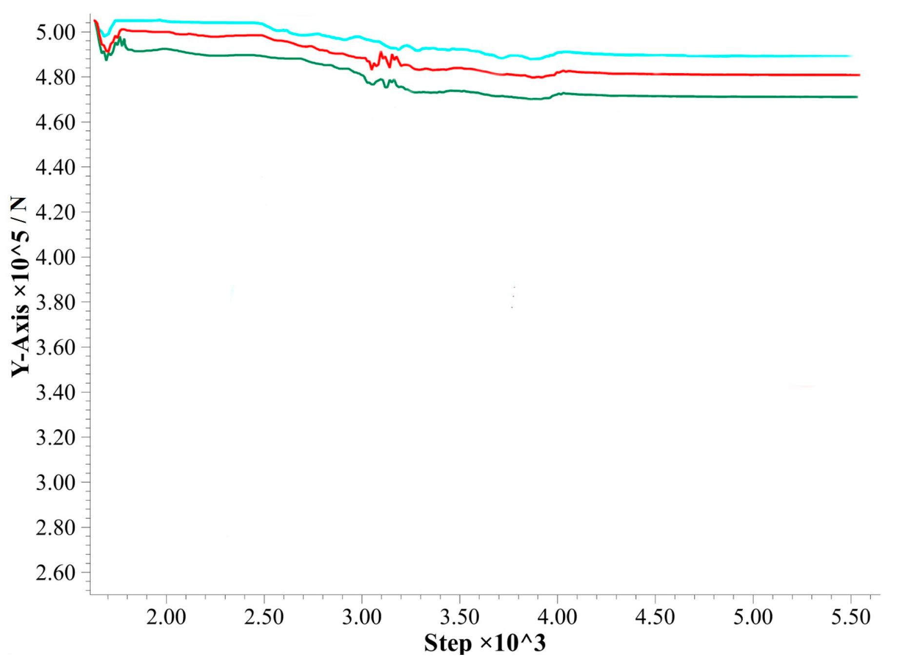
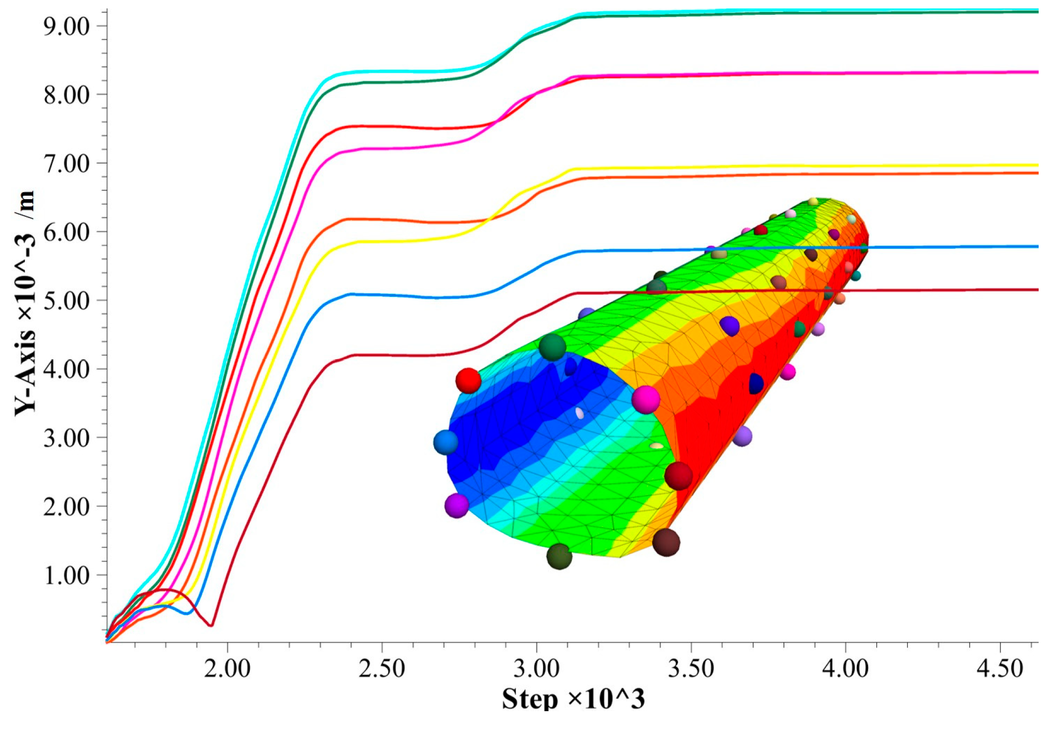
4.3. NPR Constant-Resistance Large Deformation Anchor Cable Axial Force Analysis

The NPR constant-resistance large deformation anchor cable axial force changes under the upper landslide thrust in this tunnel–landslide orthogonal system are investigated using the discount scheme in Section 3.4. In the following, the changes in axial force of the NPR constant-resistance large deformation anchor cable under five different discount schemes are analyzed.
The NPR constant-resistance large deformation anchor cable axial force analysis is carried out under the original plan (Plan 1) without reducing the shear strength parameter of the geotechnical body, and the stability analysis under the original plan in Section 3.5 shows that the tunnel–landslide orthogonal system at this time maintains a stable state. As shown in Figure 21, the axial force value of the NPR constant-resistance large deformation anchor cable initially maintains a relatively stable state under the prestressing condition with the increase in calculation steps, and then the axial force value slowly and slightly decreases to reach a stable state. The main reason is that the initial prestress of the preset NPR constant-resistance large deformation anchor cable is high, and the geotechnical body is gradually extruded to initiate slow creep deformation and a certain amount of stress relaxation occurs, which ultimately makes the axial force value of the anchor cable drop slowly and then maintain a certain constant-resistance value. At this stage, the anchor cable axial force value does not show any sudden increase or decrease, which also verifies that the tunnel–landslide orthogonal system remained relatively stable under the original scheme.
The shear strength parameters of the geotechnical body under the discounting conditions of Scheme II and III were taken to analyze the axial force of the NPR constant-resistance large deformation anchor cable, respectively. With the increase in the discount factor, as shown in Figure 22a,b with the increase in the calculation steps, the NPR constant-resistance large deformation anchor cable axial force has a sudden drop, and then increases and gradually reaches a stable state. From Section 3.6, it can be seen that at this time, small-scale landslides occur on the slope, and the tunnel settles as a whole, and at this time, the pre-added stress of the NPR constant-resistance large deformation anchor cable is released rapidly, resulting in a sudden drop in the axial force of the anchor cable. As the landslide gradually stops and reaches stability, the tunnel–landslide orthogonal system enters a new stable state, and the NPR constant-resistance large deformation anchor cable is re-tightened and maintains a certain unchanged constant-resistance value.
The shear strength parameters of the rock and soil bodies under the discounted conditions of Scenarios 4 and 5 were taken to analyze the axial force of the NPR constant-resistance large deformation anchor cable, respectively. These two schemes’ discounting parameters are larger, as can be seen from Section 3.6. At this time, the slope produces a larger-scale landslide, driving the tunnel as a whole to move along the landslide direction. As shown in Figure 23a,b, with the increase in calculation steps, the axial force of the NPR constant-resistance large deformation anchor cable has a sudden drop, and the maximum value of the sudden drop reaches nearly 200 kN. As the calculation continues, the landslide gradually reaches a new stable state, and the NPR constant-resistance large deformation anchor cable is re-tightened under the action of constant resistance and continues to maintain a certain value of constant resistance, and the axial force remains stable.

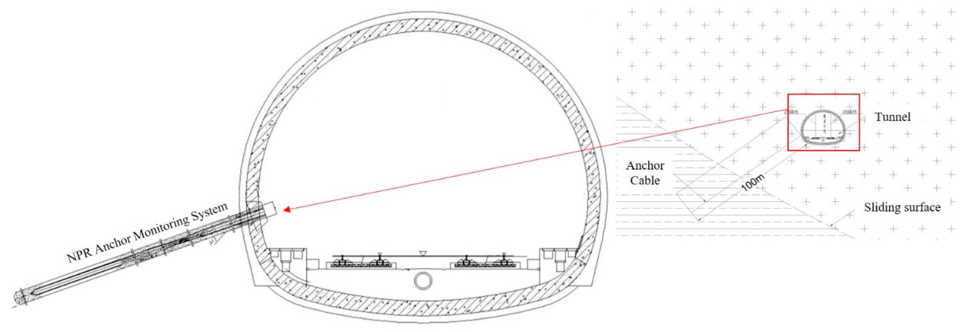
5. Establishment of Tunnel–Landslide Orthogonal System Early Warning Model and Engineering Application

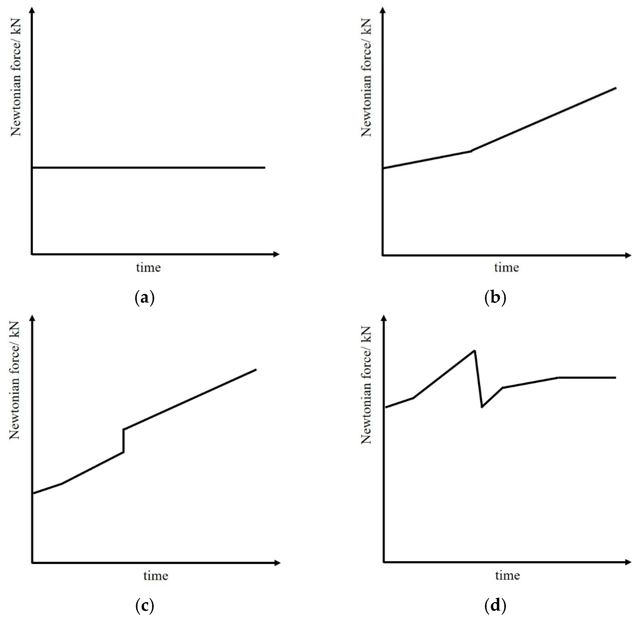
5.1. Early Warning Model of Tunnel–Landslide Orthogonal System Based on Newtonian Force Variation

Based on the numerical simulation analysis of the tunnel–landslide orthogonal system and the Newtonian force disaster warning model of landslide proposed by the Academician He Manchao, three Newtonian force monitoring and warning models of the tunnel–landslide orthogonal system were established. They are the overall stability model, slope crack model, and tunnel damage model, which systematically describe the Newtonian force characteristics during the whole process of geologic hazards in the tunnel–landslide orthogonal system.
(1)
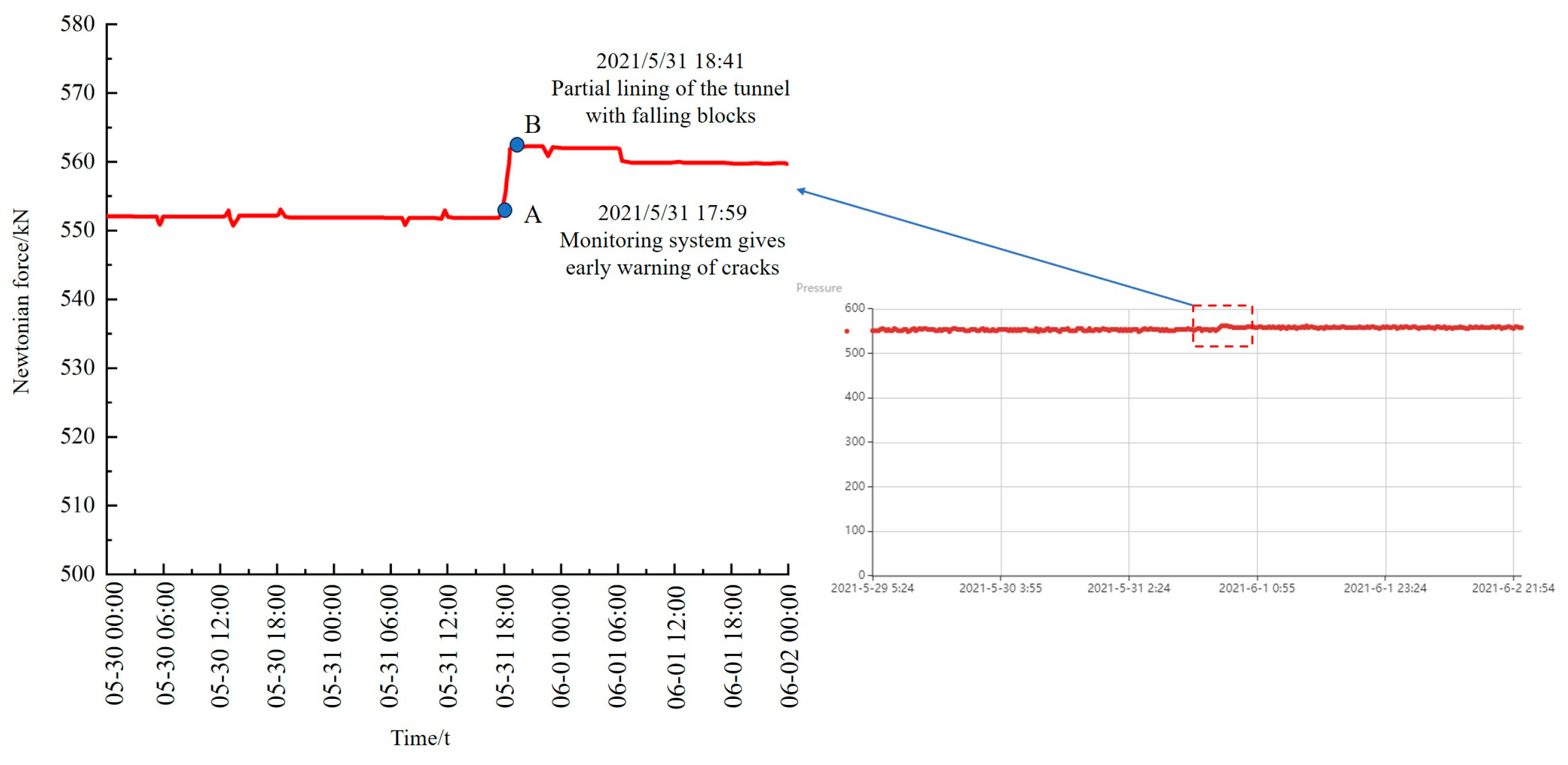
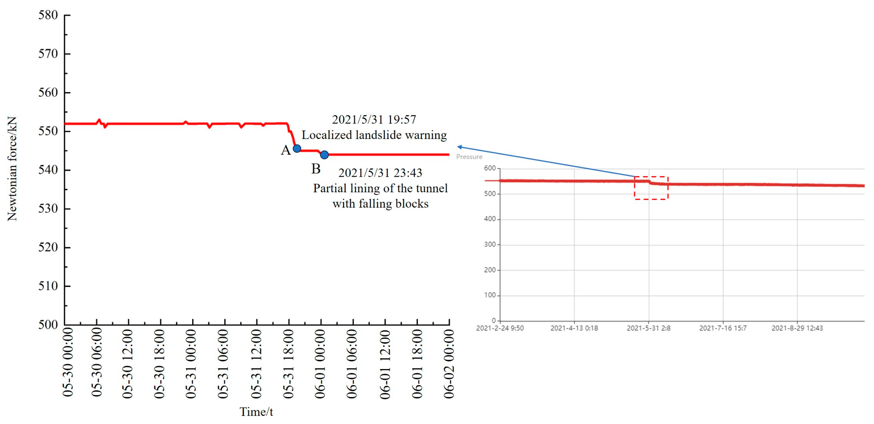
Overall stabilization mode: As shown in Figure 24a, the Newtonian force monitoring curve keeps a constant value of the vertical coordinate, and the slope is 0, which is approximated as a horizontal straight line. At this stage, the slope and the tunnel maintain a relatively stable state, and the whole tunnel–landslide orthogonal system is in a stable state.
(2)
Slope crack mode: As shown in Figure 24b,c, the Newtonian force monitoring curve shows an increasing trend with the development of time or an instantaneous surge, and the slope of the monitoring curve is greater than 0, showing a sudden increase or jump phenomenon. At this stage, continuous cracks are generated on the slope surface, and the tunnel behaves in a relatively stable state. The larger the increasing slope or jumping variable is, the larger the slope cracks are and the larger the landslide thrust on the tunnel is, and the tunnel structure will experience tension bending or shear damage, resulting in cracking of the second lining, through cracks at the top, slagging, and other phenomena, and the whole tunnel–landslide orthogonal system enters into a relatively unstable state.
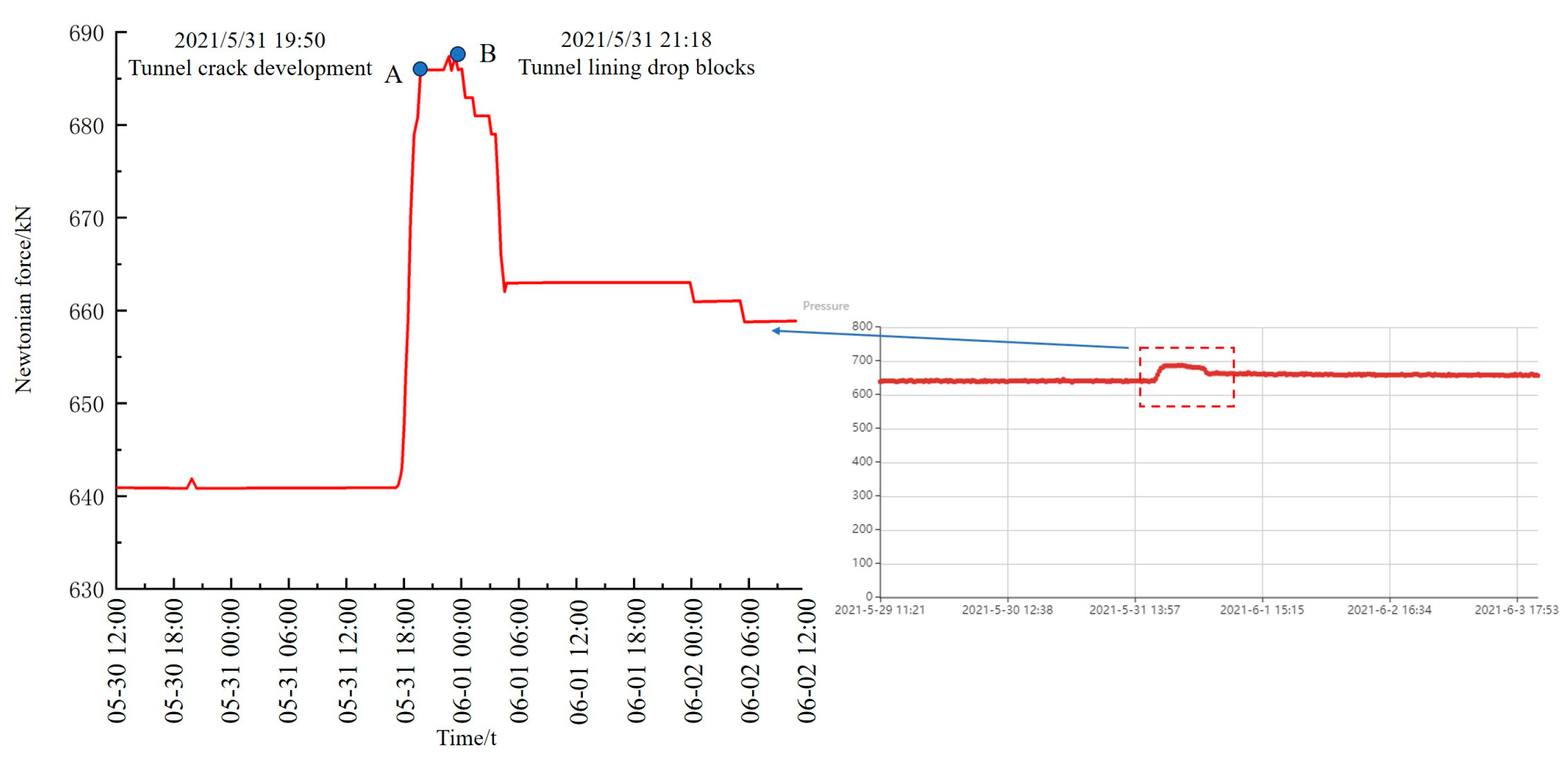
(3)
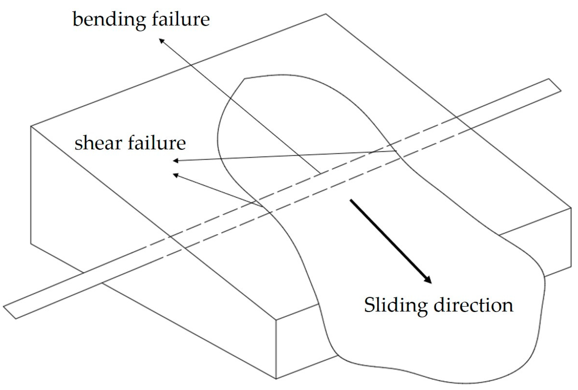
Tunnel failure mode: As shown in Figure 24d, the Newtonian force grows in a short period and there is a sudden drop. The Newtonian force monitoring curve slope from the more than 0 growth stage suddenly changes to the less than 0 decline stage, indicating that the slope surface cracks have been developed through to the interior of the slide body, with the formation of a complete sliding surface. At this stage, the landslide occurs to a greater extent, the slope will appear with large cracks and large fractures, and the tunnel by the landslide thrust exceeds the critical maximum value. There will be a greater degree of tensile bending and shear damage, and the tunnel, if located in the interior of the landslide body section of the vault, may present larger deformation or even collapse. If the tunnel is located in the external section of the landslide, circular cracks will appear at the end of the tunnel, and in serious cases, even transverse shear faults in the direction of landslide movement will occur. Newton’s force monitors the curve slope, the positive and negative turning point, which is the tunnel–landslide orthogonal system near the slip damage warning point.

5.2. Real-Time Monitoring Curve Analysis of Newtonian Force in Tunnel–Landslide Orthogonal System

The NPR constant-resistance large deformation anchor cable is used to carry out real-time early warning monitoring of a tunnel–landslide orthogonal system in northwest China as a whole [22,23,24,25], and the schematic diagram of the monitoring section inside the tunnel and the locally enlarged diagram of the tunnel–landslide system are shown in Figure 25.
At 2:04 Beijing time on 22 May 2021, a magnitude 7.4 earthquake occurred at a depth of 17 km in Maduo County, Guoluo Prefecture, Qinghai Province, China (latitude 34.59° N, longitude 98.34° E). The epicenter of the earthquake was about 384 km from Xining City and about 392 km from the tunnel studied in this paper in Haidong City.
At 17:46 Beijing time on 31 May 2021, the NPR-8 monitoring point jumped abnormally, the NPR-9 monitoring point had a small sudden drop at 17:57, and the NPR-6 monitoring point had a small sudden increase at 17:59. The Newtonian force monitoring system of the tunnel–landslide orthogonal system issued an early warning that the upper slide body might slide, the slope body had cracked, and the tunnel was about to enter an unstable state and might be damaged.
Subsequently, the curves of the three mutation points were analyzed by the hour, and a small increase in the Newtonian force occurred at 17:59 on 31 May at the Newtonian force monitoring point NPR-6, as shown in Figure 26, during which a cumulative increase of 10 kN occurred within one hour according to the on-site investigation. As shown in Figure 26, the increase amassed to 10 kN in 1 h, during which time the tunnel lining structure cracked and the cracks were in the developmental state; also, the broken structure of the tunnel vault lining broke down and fell off, according to the on-site investigation. Subsequently, the Newtonian force was maintained at 560 kN and stabilized, after which the tunnel damage gradually stabilized and no further large-scale damage occurred.
The NPR-8 Newtonian force monitoring point at 17:46 on 31 May suddenly increased, as shown in Figure 27, according to the tunnel–landslide orthogonal system early warning mode, indicating that there may be cracks developed in the tunnel or slope body. At 18:33, the Newtonian force continued to increase, according to the site investigation; at this time, accompanied by several cracks developed in the tunnel, the tunnel lining structure presented ring-direction cracks. At 22:18, the Newtonian force reached a maximum increase of 47 kN and began to decline, and a large number of local tunnel linings fell off the block. At 4:30 the next day, several cracks developed in the tunnel tracks, and the tunnel-slip system Newton force monitoring and warning system randomly issued a warning of local slip damage. Subsequently, the Newtonian force remained at 660 kN to re-achieve a stable state, after which the tunnel damage gradually stabilized and no further large-scale damage occurred.
The Newtonian force monitoring point NPR-9 experienced a sudden drop at 17:57 on 31 May, as shown in Figure 28, and based on the tunnel–landslide orthogonal system early warning model, a landslide pro-slip warning was issued. There was a possibility of small-scale sliding or cracking of the slope locally. There was a possibility that the lining of the tunnel would fall off, cracks would appear in the arch, or the lining structure as a whole would have cracks in the circumferential direction. At 18:33, the Newtonian force dropped by a cumulative total of 6 kN, and at 23:43, the force dropped again by a cumulative total of 2 kN, for a total of 8 kN. According to the on-site investigation, during this period, the tunnel lining showed obvious crack development and lining drop phenomenon. When the Newtonian force was maintained at 544 kN, the tunnel damage gradually stabilized and no further large-scale damage occurred.

6. Conclusions

(1)
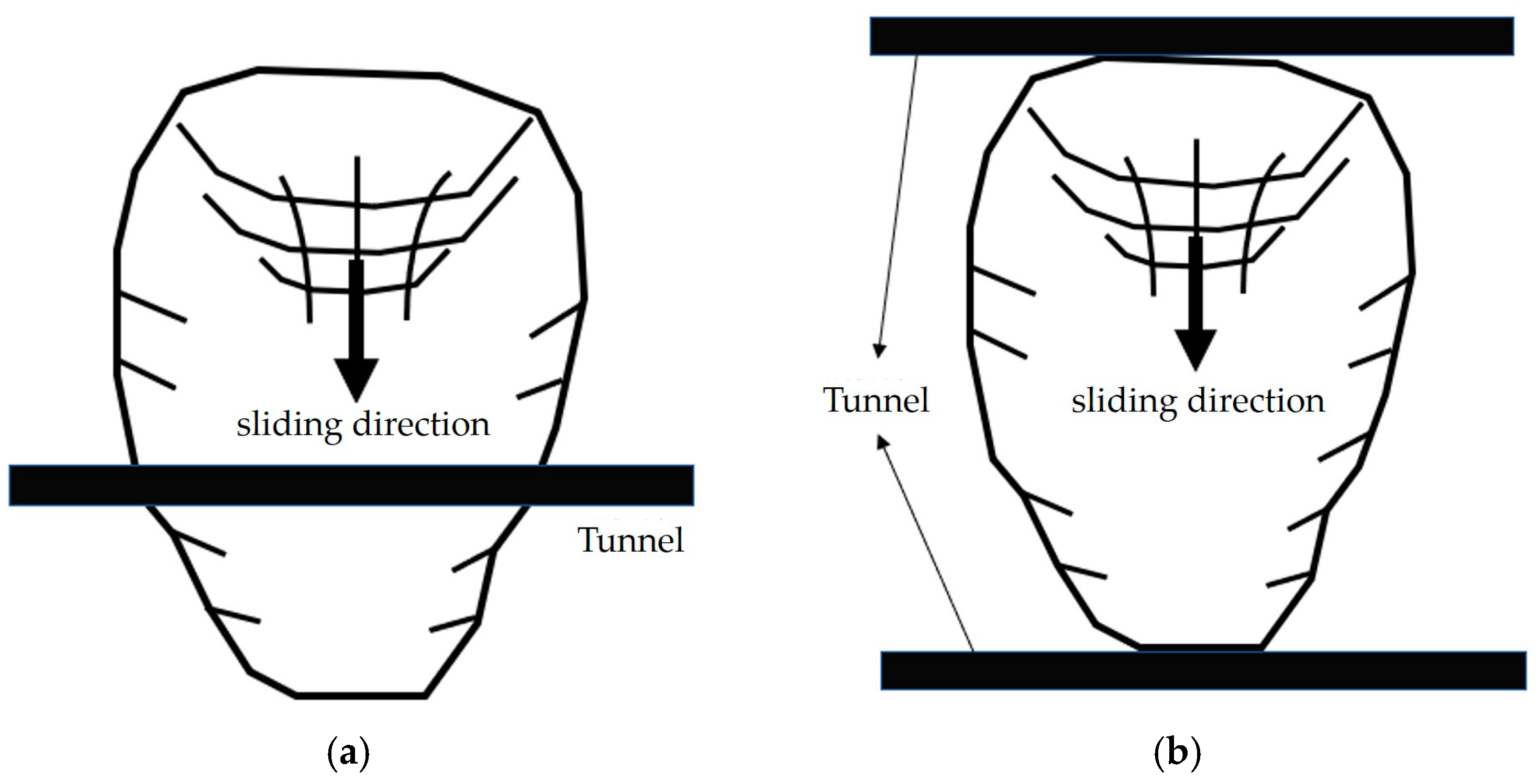
Through the stability analysis under different folding conditions, with the increase in folding coefficient, the shear strength of the rock and soil body in the slip zone decreases, resulting in a weak fragmentation zone. The upper slide body under the action of self-gravity stress gradually produces x-axis positive displacement and landslides occur. By the action of landslide thrust, the distribution of the plastic zone of the tunnel surrounding the rock changes gradually, the distribution of the tensile zone at the top and bottom decreases gradually, and the distribution of the shear zone at the left and right sides increases gradually. Therefore, tunnels located inside landslides undergo extrusion and shear damage by gravity and landslide thrust from the upper soil mass, which is accompanied by vault cracking, falling blocks, and circumferential cracks.
(2)
Through the numerical simulation analysis of the monitoring effect of the NPR constant-resistance large deformation anchor cable in the tunnel–landslide orthogonal system, with the decrease in the shear strength parameter of the geotechnical body, the tunnel–landslide orthogonal system gradually enters into the state of instability. At this time, the pre-tensioning force of the NPR constant-resistance large deformation anchor cable in the stable state is released, and the axial force undergoes a sudden drop. With the gradual cessation of landslide, the constant resistor is gradually tightened, the axial force increases again and keeps a certain constant-resistance value unchanged, and the tunnel–landslide orthogonal system enters a new stable state. It coincides with the Newtonian force disaster warning model of landslide established by the Academician He Manchao.
(3)
Based on the numerical simulation analysis of the tunnel–landslide orthogonal system and the Newtonian force disaster warning model of landslides proposed by the Academician He Manchao, three Newtonian force monitoring and warning models of the tunnel–landslide orthogonal system were established. The scientificity and authenticity of the numerical simulations are proved through the comparison of actual engineering field tests. In the natural ground stress stage, the NPR constant-resistance large deformation anchor cable axial force value is kept at a level, and the tunnel–landslide orthogonal system is in a stable state. After the seismic disturbance, the axial force of the NPR constant-resistance large deformation anchor cable increases and decreases to different degrees, and then cracks are generated in the upper slope, the tunnel lining produces through cracks and cracked blocks, and the monitoring system successfully sends out the warning of near-slip.

Author Contributions

Conceptualization, Z.T. and M.M.; methodology, M.M. and S.P.; software, M.M. and K.L.; validation, K.Q. and M.M.; formal analysis, M.M.; data curation, K.Q.; writing original draft preparation, M.M. and Z.T.; writing review and editing, Z.T.; funding acquisition, Z.T. All authors have read and agreed to the published version of the manuscript.

Funding

This research received no external funding.

Institutional Review Board Statement

Not applicable.

Informed Consent Statement

Not applicable.

Data Availability Statement

The raw data supporting the conclusions of this article will be made available by the corresponding author upon request.

Conflicts of Interest

The authors declare no conflicts of interest.

References

  1. Yamada, T.; Watari, M. Landslides and Slope Failures and Their Control; Science Press: Beijing, China, 1980. [Google Scholar]
  2. Satıcı, Ö.; Güngör, G. Effects of paleo-rock landslide and heavy rainfalls to tunnel excavation. In Proceedings of the World Tunnel Congress, Dubrovnik, Croatia, 22–27 May 2015. [Google Scholar]
  3. Zhou, D.P.; Mao, J.Q.; Zhang, L.X.; Ma, H.M. Relationship between tunnel deformation with slope disasters and its prediction model. Chin. J. China Railw. Soc. 2002, 24, 81–86. [Google Scholar]
  4. Zhu, K.; Zhu, H. Example analysis on mechanism of interaction between landslide and tunnel. Chin. J. Undergr. Space Eng. 2006, 5, 809–812+817. [Google Scholar]
  5. Ma, H.M. Discussion on problems of slope disaster and tunnel deformation. Chin. J. Rock Mech. Eng. 2003, 22 (Suppl. S2), 2719–2724. [Google Scholar]
  6. Tao, Z.; Zhou, D. Model testing research on controlling tunnel deformation in landslide field with antislide piles. Chin. J. Rock Mech. Eng. 2004, 23, 457–460. [Google Scholar]
  7. He, M.; Tao, Z.; Zhang, B. Application of remote monitoring technology in landslides in the Luoshan mining area. Min. Sci. Technol. 2009, 19, 609–614. [Google Scholar] [CrossRef]
  8. He, M. Research on the double-block mechanics based on Newton force measurement. Chin. J. Rock Mech. Eng. 2016, 35, 2161–2173. [Google Scholar]
  9. He, M. Real-time remote monitoring and forecasting system for geological disasters of landslides and its engineering application. Chin. J. Rock Mech. Eng. 2009, 28, 1081–1090. [Google Scholar]
  10. Tao, Z.; Li, H.; Sun, G.; Yin, L.; Zhang, X. Development of monitoring and early warning system for landslides based on constant resistance and large deformation anchor cable and its application. Rock Soil Mech. 2015, 36, 3032–3040. [Google Scholar]
  11. Yang, X.; Hou, D.; Hao, Z.; Tao, Z.; Shi, H.; Jin, K. Study on the stability and remote real-time monitoring for high steep slope in Nanfen open pit iron mine. J. Min. Saf. Eng. 2017, 34, 1000–1007. [Google Scholar]
  12. Li, B.; Zhang, Q.; Wang, W.; Zhao, Q.; Wang, C.; He, K.; Gao, Y.; Zhang, X. Geohazard monitoring and risk management of high-steep slope in the Wudongde dam area. J. Geomech. 2020, 26, 556–564. [Google Scholar]
  13. Su, M.; Liu, Y.; Xue, Y.; Cheng, K.; Ning, Z.; Li, G.; Zhang, K. Detection method of karst features around tunnel construction by multi-resistivity data-fusion pseudo-3D-imaging based on the PCA approach. Eng. Geol. 2021, 288, 106127. [Google Scholar] [CrossRef]
  14. Zhou, W. Analysis of Landslide-Tunnel Interaction and Control Measures. Ph.D. Thesis, China Academy of Railway Research, Beijing, China, 2020. [Google Scholar]
  15. Wu, H.; Wu, D.; Ma, H.; Zhang, L. Research of type of tunnel-landslide system and tunnel deformation mode. Chin. J. Rock Mech. Eng. 2012, 31 (Suppl. S2), 3632–3642. [Google Scholar]
  16. Qiang, X. Understanding the landslide monitoring and early warning: Consideration to practical issues. J. Eng. Geol. 2020, 28, 360–374. [Google Scholar] [CrossRef]
  17. Wu, H.; Chen, X.; Ai, H. Research on the force exerting mode model test of tunnel-landslide orthogonal system. J. Railw. Eng. Soc. 2016, 33, 1–5. [Google Scholar]
  18. Lyness, J.F.; Owen, D.R.J.; Zienkiewicz, O.C. The finite element analysis of engineering systems governed by a non-linear quasi-harmonic equation. Comput. Struct. 1975, 5, 65–79. [Google Scholar] [CrossRef]
  19. Chen, G.Q.; Huang, R.Q.; Shi, Y.C.; Xu, Q. Stability analysis of slope based on dynamic and whole strength reduction methods. Chin. J. Rock Mech. Eng. 2014, 33, 243–256. [Google Scholar] [CrossRef]
  20. Xu, W.; Sun, W.; Jiang, L.; Wang, R. Exploring the influence of slope boundary extent on stability calculation in FLAC3D numerical simulation. Road Traffic Sci. Technol. Appl. Technol. Ed. 2019, 15, 8–9. [Google Scholar]
  21. Tao, Z.; Wang, Y.; Zhu, C.; Xu, H.; Li, G.; He, M. Mechanical evolution of constant resistance and large deformation anchor cables and their application in landslide monitoring. Bull. Eng. Geol. Environ. 2019, 78, 4787–4803. [Google Scholar] [CrossRef]
  22. Wang, F.N.; Guo, Z.B.; Qiao, X.B.; Fan, J.Y.; Li, W.; Mi, M.; He, M.C. Large deformation mechanism of thin-layered carbonaceous slate and energy coupling support technology of NPR anchor cable in Minxian Tunnel: A case study. Tunn. Undergr. Space Technol. 2021, 117, 104151. [Google Scholar] [CrossRef]
  23. Zhang, Y.; Li, H.; Sheng, Q.; Wu, K.; Chen, G. Real time remote monitoring and pre-warning system for Highway landslide in mountain area. J. Environ. Sci. 2011, 23, S100–S105. [Google Scholar] [CrossRef] [PubMed]
  24. Guo, Y. Stability Evaluation of Highway Rocky Slopes Based on Anchor Axial Force Monitoring. Ph.D. Thesis, Chang’an University, Xi’an, China, 2011. [Google Scholar]
  25. Xu, Q.; Peng, D.; He, C.; Qi, X.; Zhao, K.; Xiu, D. Theory and method of monitoring and early warning for sudden loess landslide—A case study at Heifangtai terrace. J. Eng. Geol. 2020, 28, 111–121. [Google Scholar] [CrossRef]
Figure 1. Topographic and geomorphological map of the tunnel passing through the landslide.
Applsci 14 02790 g001
Figure 2. Meso-view map of landslide disaster above the tunnel.
Applsci 14 02790 g002
Figure 3. Site map of tunnel damage caused by landslide. (a) Tunnel vault penetration split, (b) tunnel vault dropout.
Applsci 14 02790 g003
Figure 4. Section of engineering geology of tunnel deep geological hazard body II-II’.
Applsci 14 02790 g004
Figure 5. Schematic diagram of two cases of tunnel–landslide orthogonal system on the plane. (a) Intersection of tunnel and landslide, (b) tunnels located outside the landslide.
Applsci 14 02790 g005
Figure 6. Schematic diagram of the relative position of the tunnel in the tunnel–landslide orthogonal system.
Applsci 14 02790 g006
Figure 7. Schematic diagram of the stress on the cross-section of the tunnel located inside the landslide body.
Applsci 14 02790 g007
Figure 8. Schematic diagram of the forced failure of the landslide body under the tunnel.
Applsci 14 02790 g008
Figure 9. Numerical simulation II-II’ of simplified layered diagram of landslide section.
Applsci 14 02790 g009
Figure 10. Solid modeling of the tunnel–landslide system. (a) Integral model of the tunnel–landslide system, (b) grid local encryption, (c) tunnel lining structures.
Applsci 14 02790 g010
Figure 11. Sliding belt model contact surface establishment.
Applsci 14 02790 g011
Figure 12. Model boundary constraint condition setting.
Applsci 14 02790 g012
Figure 13. Cloud map of horizontal displacement of slope after tunnel excavation is completed.
Applsci 14 02790 g013
Figure 14. Vector illustration of tunnel displacement after tunnel excavation is completed.
Applsci 14 02790 g014
Figure 15. Tunnel lining structure monitoring points and displacement curve.
Applsci 14 02790 g015
Figure 16. Cloud map of horizontal displacement of slope under different reduction schemes. (a) Plan 2, (b) Plan 3, (c) Plan 4, (d) Plan 5.
Applsci 14 02790 g016
Figure 17. Settlement monitoring curve of tunnel lining structure under different reduction schemes. (a) Plan 1, (b) Plan 2, (c) Plan 3, (d) Plan 4, (e) Plan 5.
Applsci 14 02790 g017
Figure 18. Plastic zone of rock and soil mass around tunnel under different reduction schemes. (a) Plan 1, (b) Plan 2, (c) Plan 3, (d) Plan 4, (e) Plan 5.
Applsci 14 02790 g018
Figure 19. Numerical model for early warning monitoring of NPR anchor cable slipping. (a) NPR constant-resistance large deformation anchor spatial location. (b) NPR constant-resistance large deformation anchor cable section.
Applsci 14 02790 g019
Figure 20. NPR constant-resistance large deformation anchor cable initial prestress.
Applsci 14 02790 g020
Figure 21. Monitoring the axial force of the anchor cable under the original scheme.
Applsci 14 02790 g021
Figure 22. Monitoring the axial force of the anchor cable under the conditions of schemes 2 and 3. (a) Plan 2, (b) Plan 3.
Applsci 14 02790 g022
Figure 23. Monitoring the axial force of the anchor cable under the conditions of schemes 4 and 5. (a) Plan 4, (b) Plan 5.
Applsci 14 02790 g023
Figure 24. Newton force monitoring and early warning model of tunnel–landslide orthogonal system. (a) Overall stabilization mode, (b) Slope crack mode1, (c) Slope crack mode2, (d) Tunnel failure mode.
Applsci 14 02790 g024
Figure 25. Schematic of the Newtonian force monitoring section inside the tunnel.
Applsci 14 02790 g025
Figure 26. Variation of NPR-6 Newton force curve and tunnel failure characteristics.
Applsci 14 02790 g026
Figure 27. Variation of NPR-8 Newton force curve and tunnel failure characteristics.
Applsci 14 02790 g027
Figure 28. Variation of NPR-9 Newton force curve and tunnel failure characteristics.
Applsci 14 02790 g028
Table 1. Values of physical and mechanical parameters of materials.
StratificationGravity
k N · m 3
Elastic
Modulus
MPa
Poisson RatioAngle of
Internal
Friction
°
Force of
Cohesion
kPa
moderately weathered sandstone-mudstone218000.3537200
strongly weathered sandstone-mudstone206000.32852.5
fully weathered sandstone-mudstone202000.322230
sliding belt18800.3517.1320.1
loess191000.352715
earth fill181000.352813
Table 2. Design of reduction scheme for shear strength parameters of slide belt 1.
Plan NameReduction CoefficientThe Angle of Internal Friction of the Sliding Belt
°
Cohesion
kPa
Plan 1 (original plan)117.1320.1
Plan 21.214.2816.75
Plan 31.313.1715.46
Plan 41.412.2314.36
Plan 51.511.4213.40
Table 3. Design of reduction scheme for shear strength parameters of slide belt 2.
Plan NameReduction CoefficientThe Angle of Internal Friction of the Sliding Belt
°
Cohesion
kPa
Plan 1 (original plan)116.3519.3
Plan 21.213.6316.08
Plan 31.312.5814.85
Plan 41.411.6813.79
Plan 51.510.912.87
Table 4. Design of reduction scheme for shear strength parameters of slide belt 3.
Plan NameReduction CoefficientThe Angle of Internal Friction of the Sliding Belt
°
Cohesion
kPa
Plan 1 (original plan)118.6422.6
Plan 21.215.5318.83
Plan 31.314.3417.38
Plan 41.413.3116.14
Plan 51.512.4315.07
Disclaimer/Publisher’s Note: The statements, opinions and data contained in all publications are solely those of the individual author(s) and contributor(s) and not of MDPI and/or the editor(s). MDPI and/or the editor(s) disclaim responsibility for any injury to people or property resulting from any ideas, methods, instructions or products referred to in the content.

