

The Effect of a New Approach to Cooling the External Heat Exchange Surfaces of a Car Cooler with Air Nozzles on the Cooling Process


Abstract
1. Introduction
2. Materials and Methods
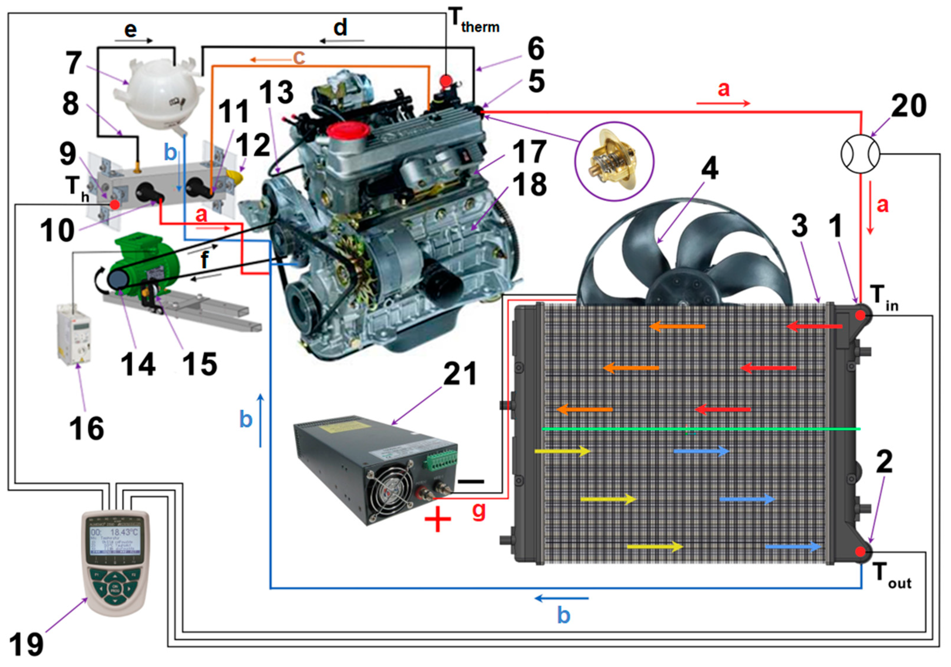
2.1. Experimental Setup of the Cooling Circuit with the Fan
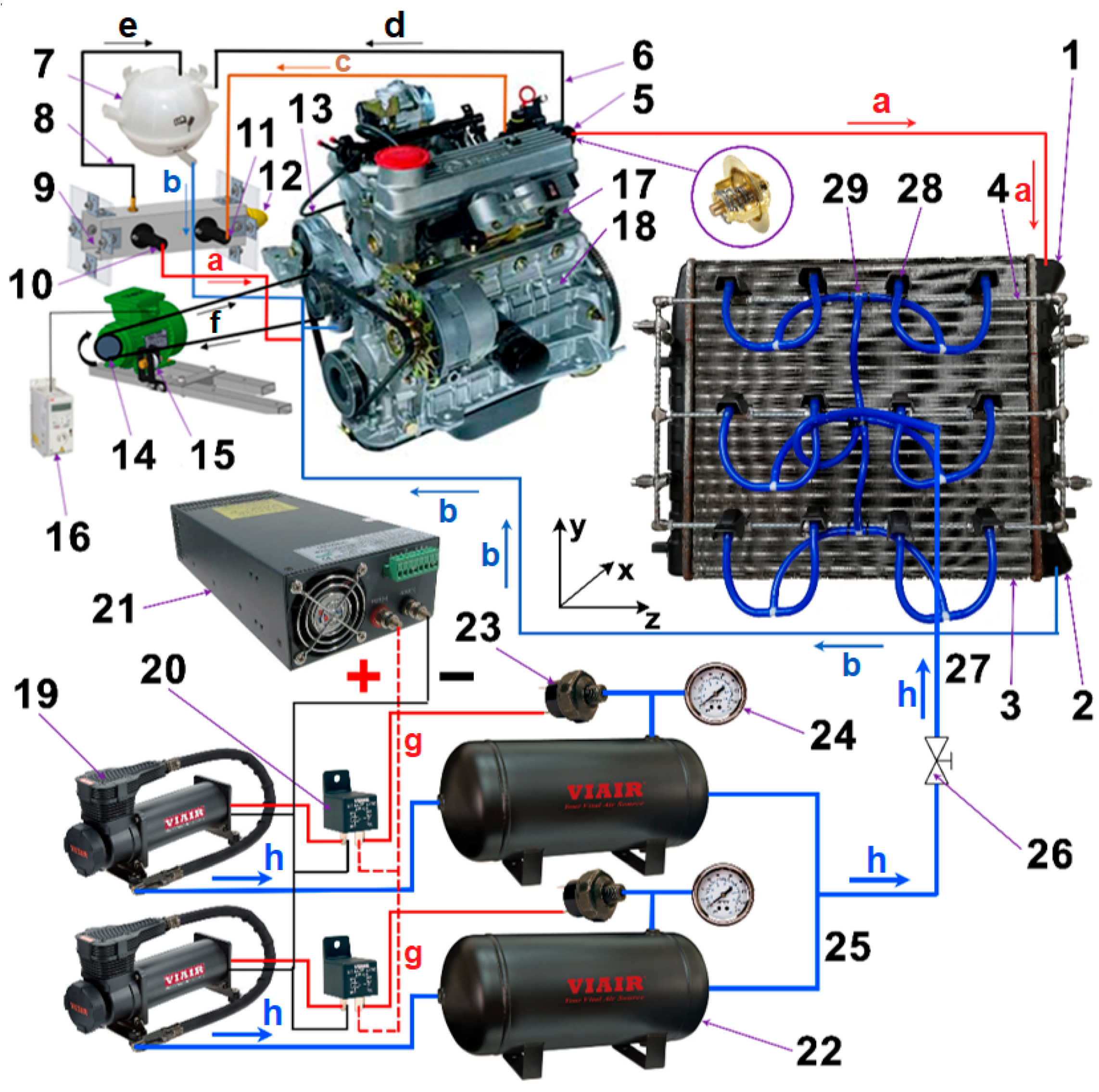
2.2. Experimental Setup of the Cooling Circuit with the Pneumatic Pressure Nozzles
3. Results
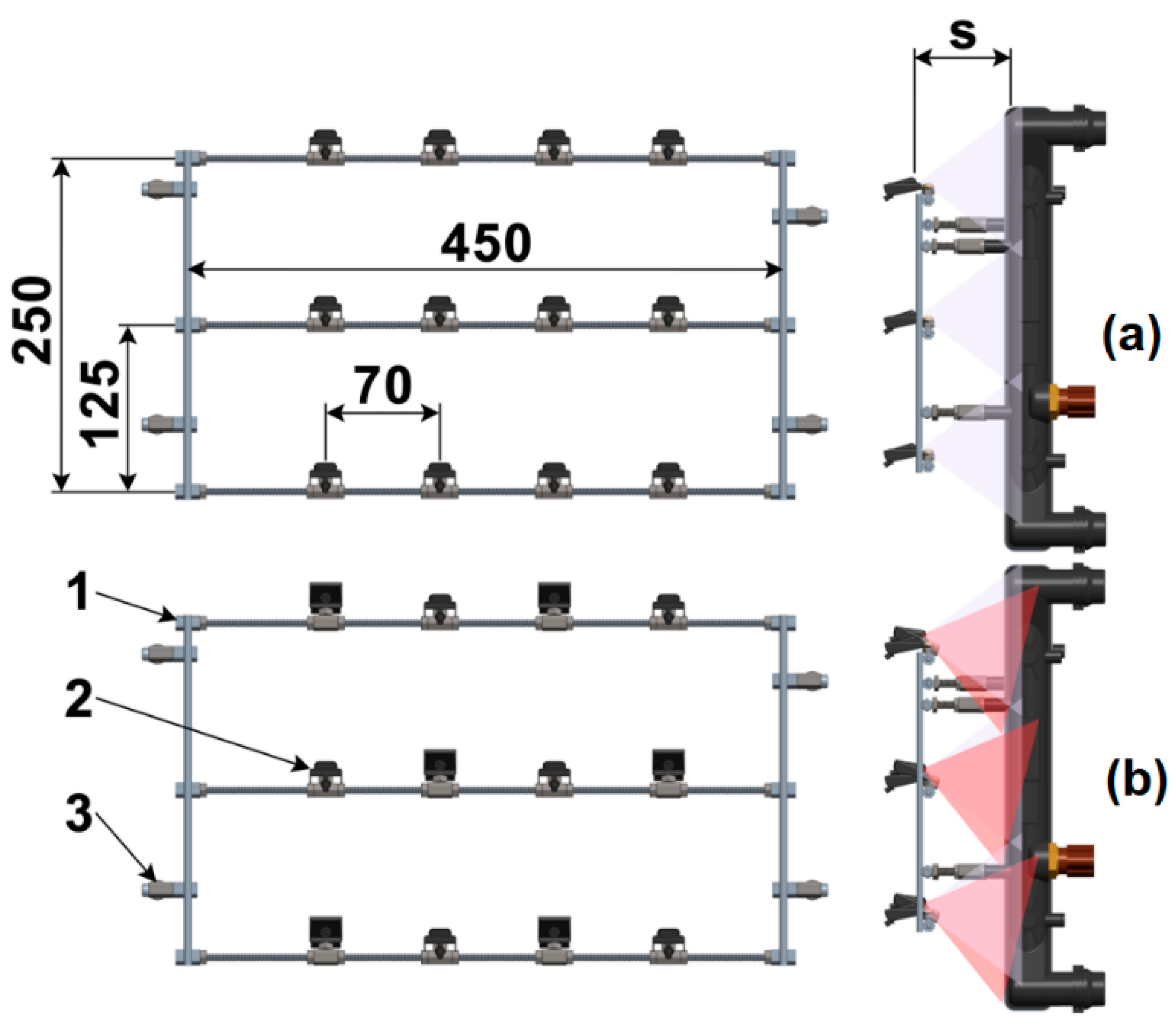
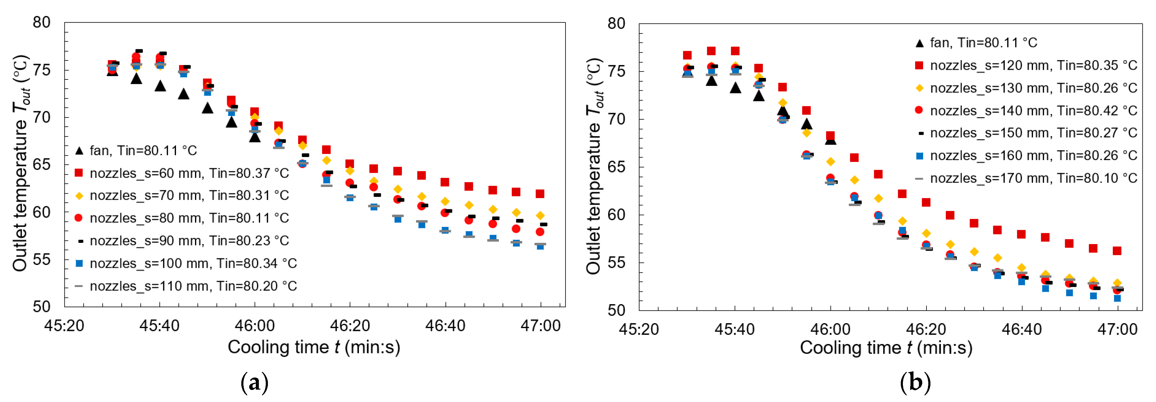
3.1. Inline Arrangement of the Nozzles
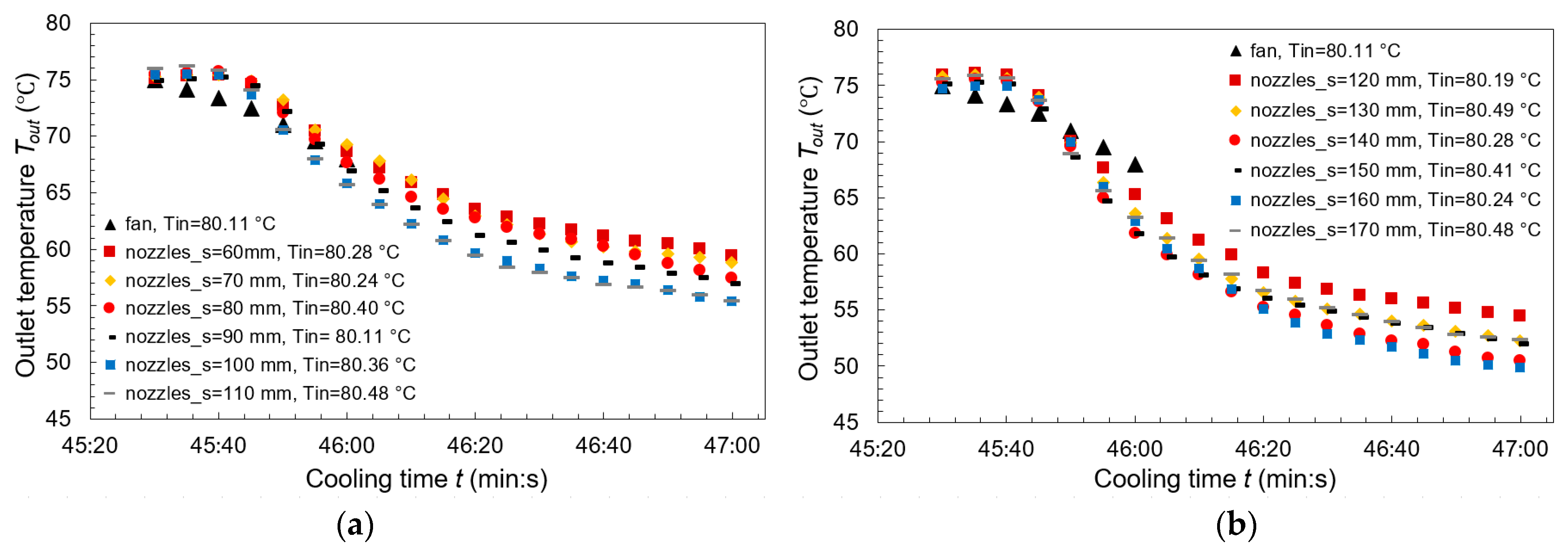
3.2. Staggered Arrangement of the Nozzles
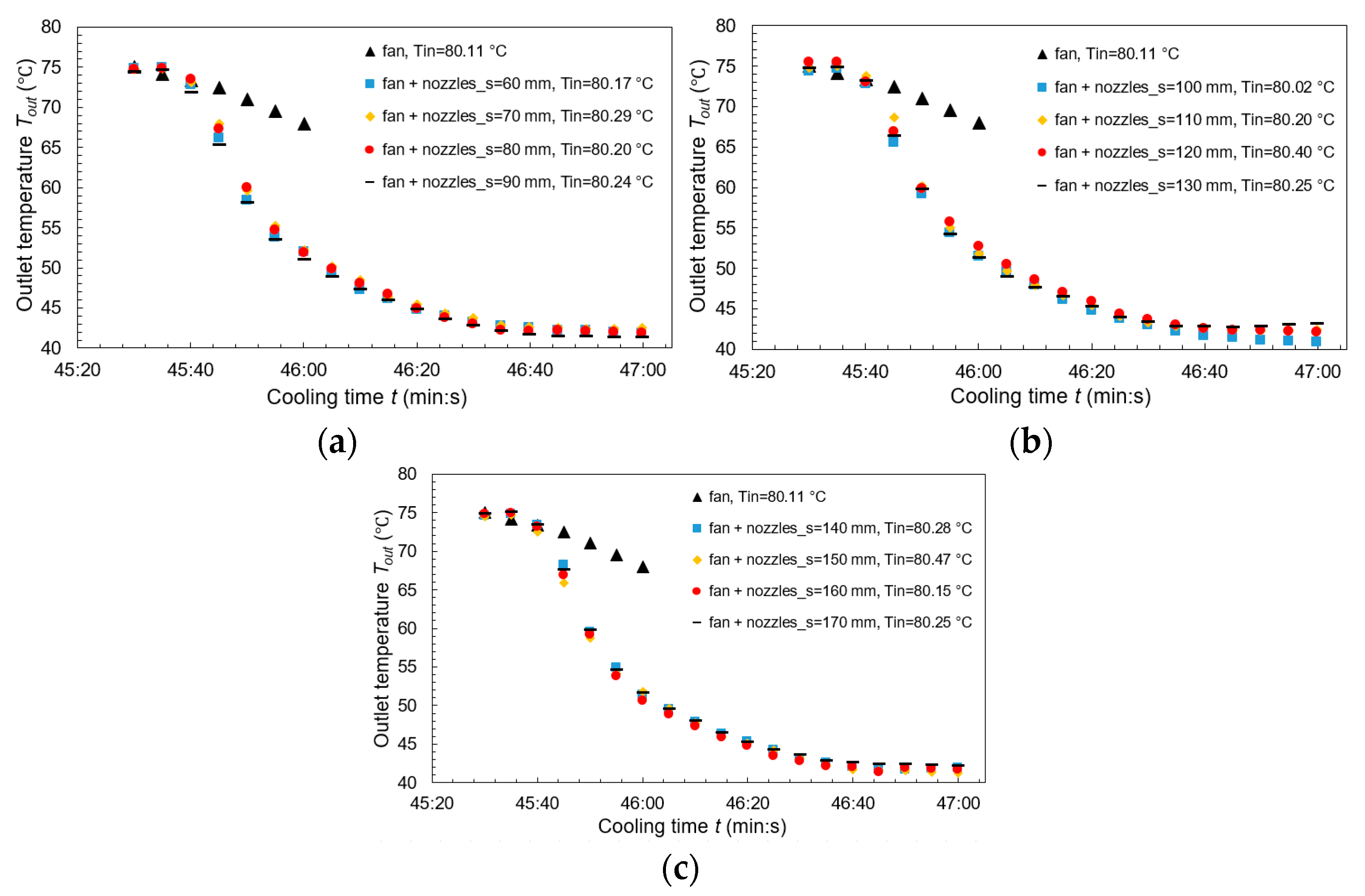
3.3. Combination of the Inline Arrangement of the Nozzles and Fan
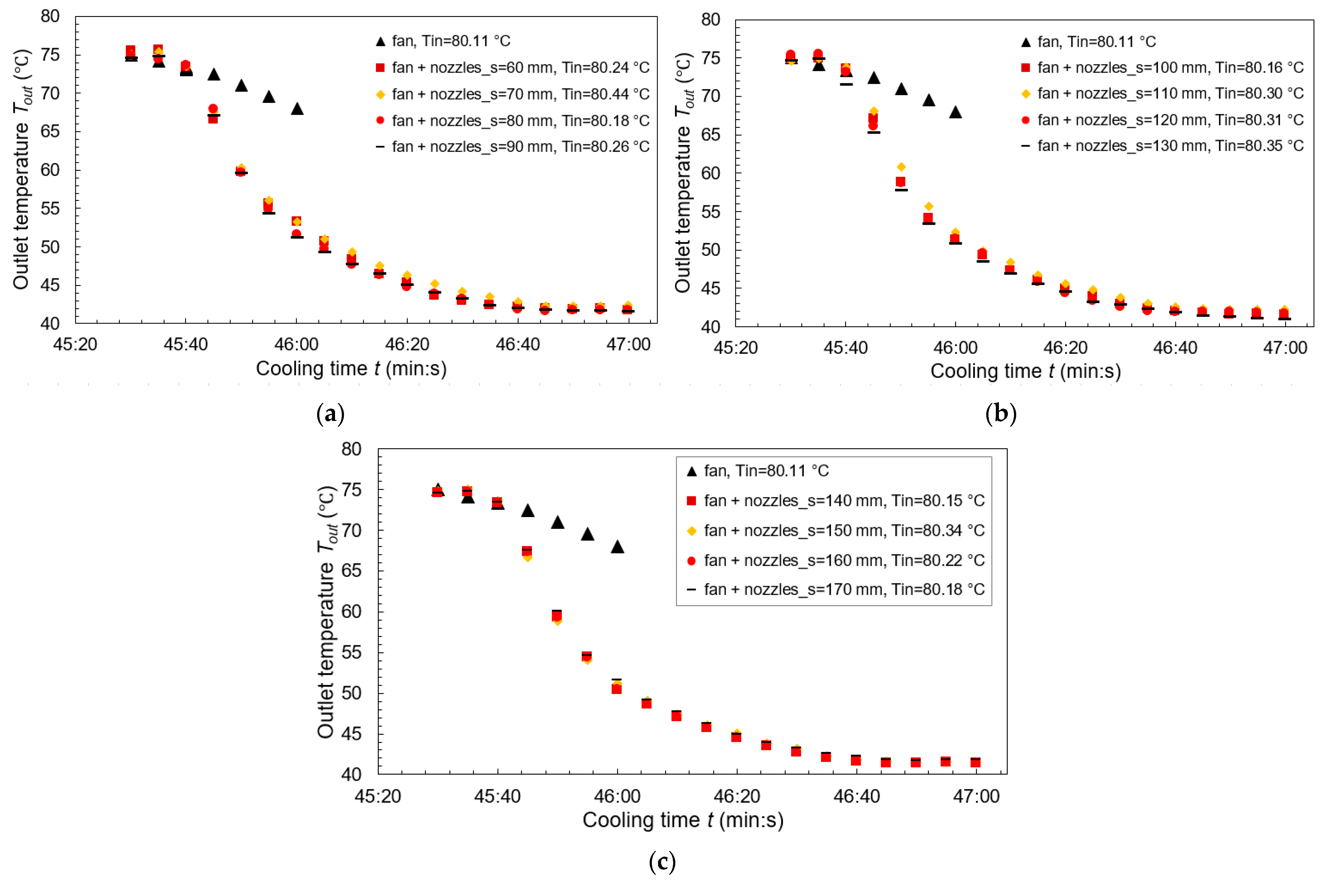
3.4. Combination of the Staggered Arrangement of the Nozzles and Fan
3.5. Comparison of the Combinations of Cooling Systems Studied
4. Conclusions
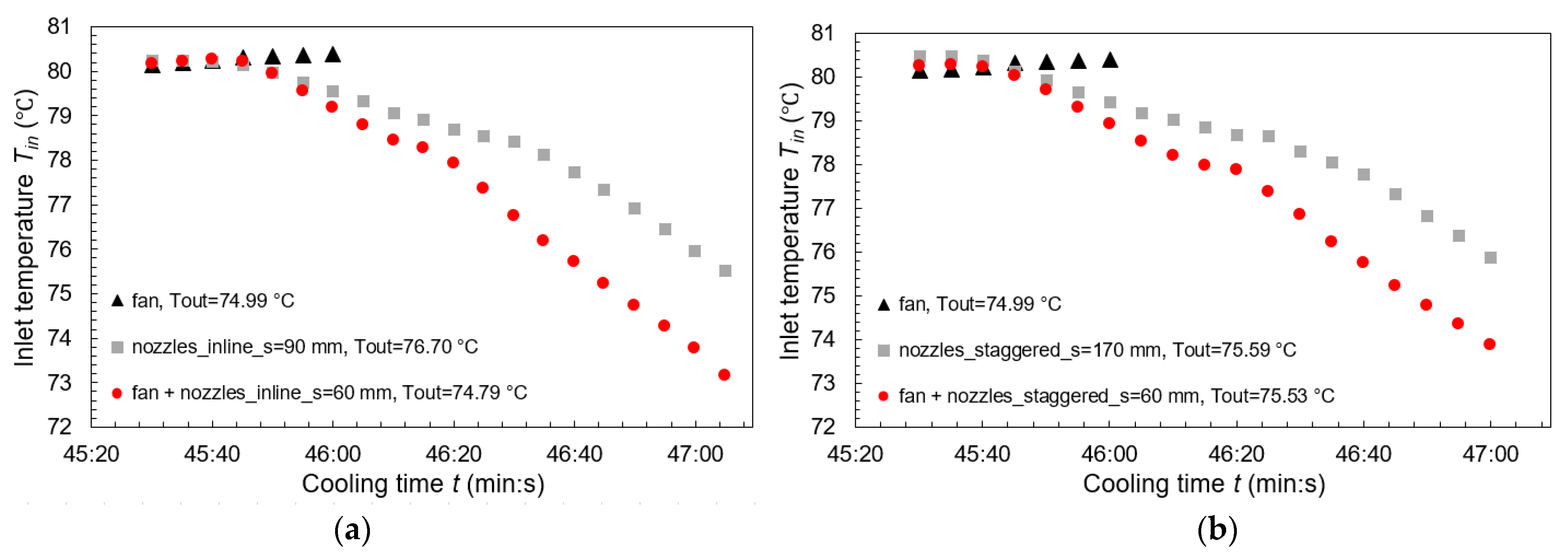
- Inline arranged nozzles with a spacing of 130 to 170 mm achieved an improvement in the cooling process of about 5 °C compared with the fan in a time of 46 min.
- Staggered nozzle arrangement solves the problem of empty spots on the cooler that are not covered by air in the case of an inline arrangement. The staggered arrangement of the nozzles with spacing of 80 mm to 170 mm have reached a more effective cooling efficiency throughout the entire cooling process compared to the fan. At a spacing of 160 mm of the staggered arranged nozzles, the cooling process was improved by more than 6 °C compared with the fan in 46 min. When compared with the minimum spacing of 60 mm, the spacing of 160 mm of staggered arranged nozzles showed an improvement in the cooling process of nearly 10 °C.
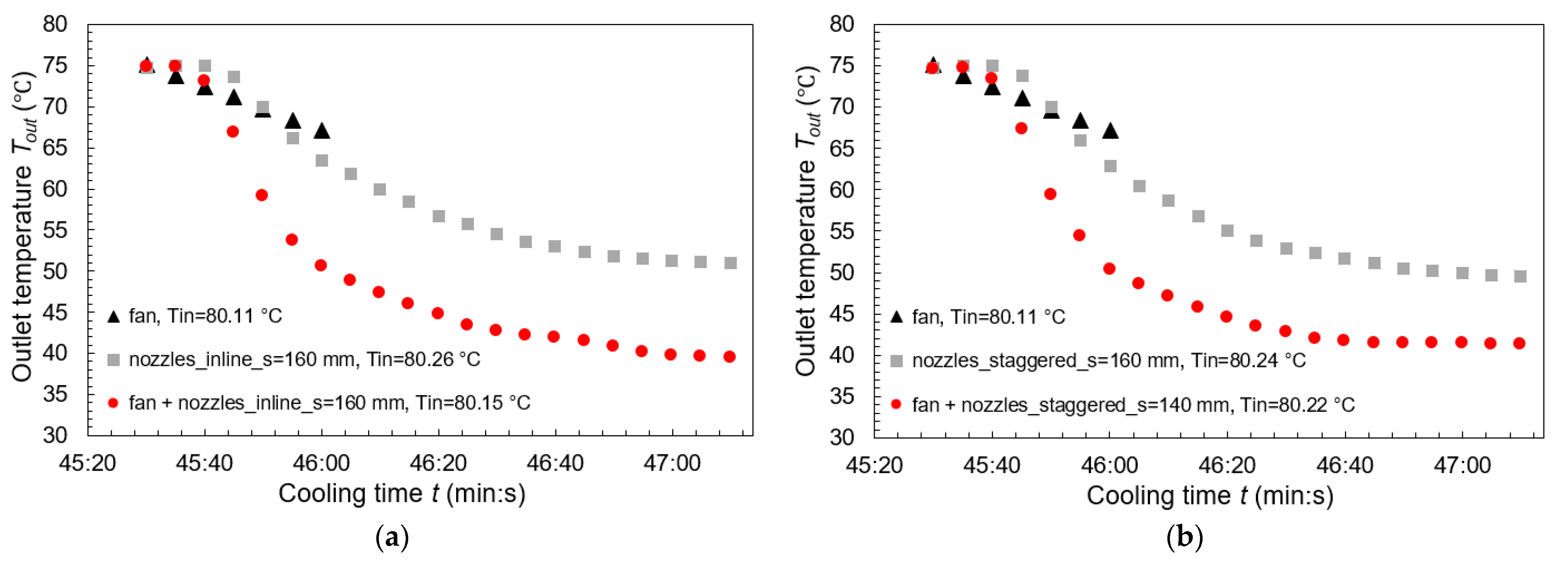
- The combination of the inline arrangement of the nozzles and fan provided a decrease in the cooler outlet temperature of 17.38 °C for a spacing of 160 mm in a time of 46 min compared to fan-only cooling.
- The combination of the staggered arrangement of the nozzles and fan provided a cooler outlet temperature reduction of 17.61 °C for a 140 mm spacing in a time of 46 min compared to fan-only cooling. Further increase in the spacing was already causing an increase in the cooler outlet temperature and deterioration of the cooling process.
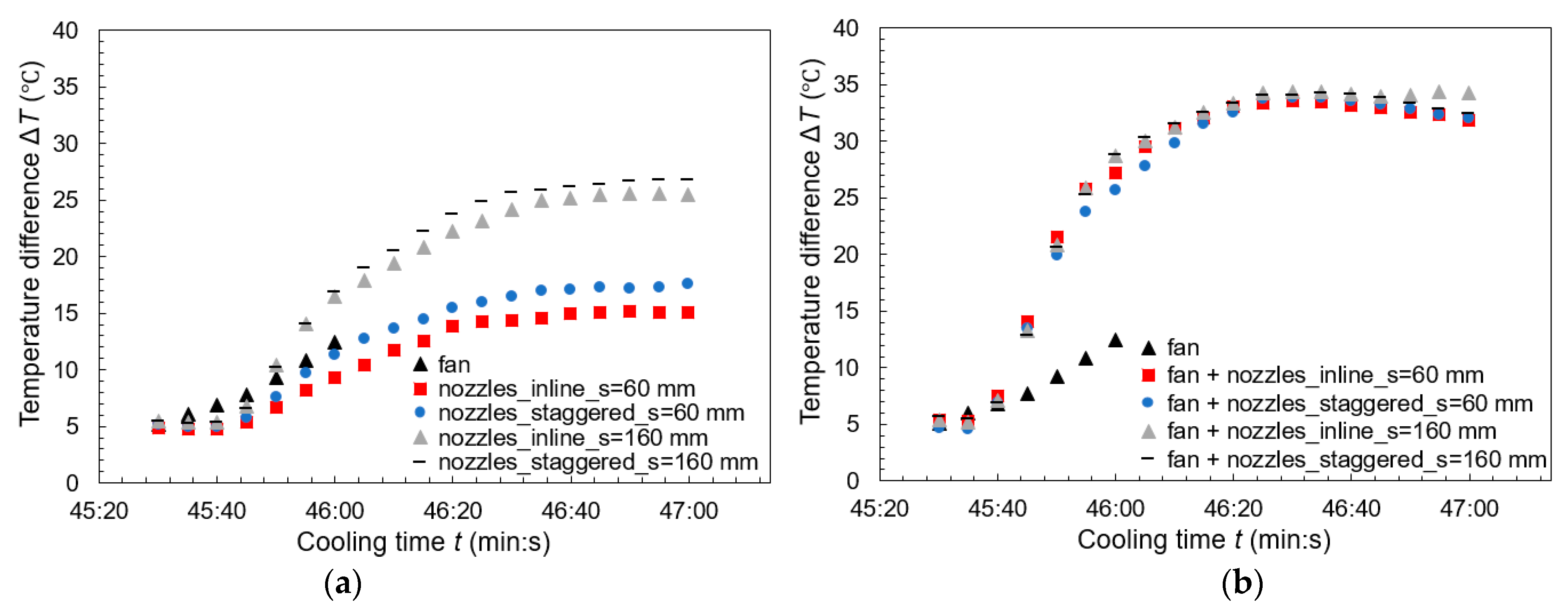
- As the distance of the nozzles from the cooler increases, complete coverage of the heat exchange surface by the air flow is ensured, which leads to a reduction in the cooling time of the coolant and an increase in the temperature difference.
- When comparing the temperature differences for the fan and nozzle over a time of 46 min, the maximum ΔT = 16.9 °C and 16.49 °C are achieved by the nozzles at a spacing of 160 mm in the staggered and inline arrangements, respectively. A minimum spacing of 60 mm is even less efficient than using only the fan.
- When comparing the temperature differences for the fan and combination fan and nozzles over a time of 46 min, the maximum ΔT = 28.84 °C and 28.72 °C are achieved by the combination of fan and nozzles at a spacing of 160 mm in the staggered and inline arrangements, respectively.
- The thermal performance increased as the spacing between the air nozzles and the cooler increased up to a spacing of 160 mm. Over this value, the cooling process already deteriorates. When comparing 60 mm and 160 mm spacing, there was an increase in thermal performance of 70.3%, 55.99%, 6.20% and 1.83% for inline nozzles, staggered nozzles, fan with inline nozzles and fan with staggered nozzles, respectively.
Author Contributions
Funding
Institutional Review Board Statement
Informed Consent Statement
Data Availability Statement
Conflicts of Interest
References
- Sidik, N.A.C.; Yazid, M.N.A.W.M.; Mamat, R. Recent advancement of nanofluids in engine cooling system. Renew. Sustain. Energ. Rev. 2017, 75, 137–144. [Google Scholar] [CrossRef]
- Bigdeli, M.B.; Fasano, M.; Cardellini, A. A review on the heat and mass transfer phenomena in nanofluid coolants with special focus on automotive applications. Renew. Sustain. Energ. Rev. 2016, 60, 1615–1633. [Google Scholar] [CrossRef]
- Leong, K.Y.; Saidur, R.; Kazi, S.N.; Hamun, A.H. Performance investigation of an automotive car radiator operated with nanofluid-based coolants (nanofluid as a coolant in a radiator). Appl. Therm. Eng. 2010, 30, 2685–2692. [Google Scholar] [CrossRef]
- Gupta, M.; Singh, V.; Kumar, R.; Said, Z. A review on thermophysical properties of nanofluids and heat transfer applications. Renew. Sustain. Energ. Rev. 2017, 74, 638–670. [Google Scholar] [CrossRef]
- Zhao, N.; Li, S.; Yang, J. A review on nanofluids: Data-driven modelling of thermophysical properties and the application in automotive radiator. Renew. Sustain. Energ. Rev. 2016, 66, 596–616. [Google Scholar] [CrossRef]
- Chen, X.; Yu, X.; Lu, Y.; Huang, R.; Liu, Z.; Huang, Y.; Roskilly, A.P. Study of different cooling structures on the thermal status of an Internal Combustion Engine. Appl. Therm. Eng. 2017, 116, 419–432. [Google Scholar] [CrossRef]
- Fontanesi, S.; Giacopini, M. Multiphase CFD–CHT optimization of the cooling jacket and FEM analysis of the engine head of a V6 diesel engine. Appl. Therm. Eng. 2013, 52, 293–303. [Google Scholar] [CrossRef]
- Mukkamala, Y. Contemporary trends in thermo-hydraulic testing and modeling of automotive radiators deploying nano-coolants and aerodynamically efficient air-side fins. Renew. Sustain. Energ. Rev. 2017, 76, 1208–1229. [Google Scholar] [CrossRef]
- Pang, S.C.; Kalam, M.A.; Masjuki, H.H.; Hazrat, M.A. A review on air flow and coolant flow circuit in vehicles’ cooling system. Int. J. Heat Mass Transf. 2012, 55, 6295–6306. [Google Scholar] [CrossRef]
- Cipollone, R.; Battista, D.D.; Gualtieri, A. A novel engine cooling system with two circuits operating at different temperatures. Energy Convers. Manag. 2013, 75, 581–592. [Google Scholar] [CrossRef]
- Cippolone, R.; Di Battista, D. Sliding vane rotary pump in engine cooling system for automotive sector. Appl. Therm. Eng. 2015, 76, 157–166. [Google Scholar] [CrossRef]
- Chastain, J.; Wagner, J.; Eberth, J. Advanced engine cooling—Components, testing and observations. IFAC Proc. Vol. 2010, 43, 294–299. [Google Scholar] [CrossRef]
- Amrutkar, P.S.; Patil, S.R. Automotive radiator performance—Review. Int. J. Eng. Adv. Technol. 2013, 2, 563–565. [Google Scholar]
- Khaled, M.; Mangi, F.; El Hage, H.; Harambat, F.; Peerhossaini, H. Fan air flow analysis and heat transfer enhancement of vehicle underhood cooling system—Towards a new control approach for fuel consumption reduction. Appl. Energy 2012, 91, 439–450. [Google Scholar] [CrossRef]
- Said, Z.; El Haj Assad, M.; Hachicha, A.A.; Bellos, E.; Abdelkareem, M.A.; Alazaizeh, D.Z.; Yousef, B.A. Enhancing the performance of automotive radiators using nanofluids. Renew. Sustain. Energ. Rev. 2019, 112, 183–194. [Google Scholar] [CrossRef]
- Mohamed, E.S. Development and analysis of a variable position thermostat for smart cooling system of a light duty diesel vehicles and engine emissions assessment during NEDC. Appl. Therm. Eng. 2016, 99, 358–372. [Google Scholar] [CrossRef]
- Haghighat, A.K.; Roumi, S.; Madani, N.; Bahmanpour, D.; Olsen, M.G. An intelligent cooling system and control model for improved engine thermal management. Appl. Therm. Eng. 2018, 128, 253–263. [Google Scholar] [CrossRef]
- Shin, Y.H.; Kim, S.C.; Kim, M.S. Use of electromagnetic clutch water pumps in vehicle engine cooling systems to reduce fuel consumption. J. Energy 2013, 57, 624–631. [Google Scholar] [CrossRef]
- Taymaz, I.; Çakır, K.; Mimaroglu, A. Experimental study of effective efficiency in a ceramic coated diesel engine. Surf. Coat. Technol. 2005, 200, 1182–1885. [Google Scholar] [CrossRef]
- Subhedar, D.G.; Ramani, B.M.; Gupta, A. Experimental investigation of heat transfer potential of Al2O3/Water-Mono Ethylene Glycol nanofluids as a car radiator coolant. Case Stud. Therm. Eng. 2018, 11, 26–34. [Google Scholar] [CrossRef]
- Kulkarni, D.P.; Vajjha, R.S.; Das, D.K.; Oliva, D. Application of aluminum oxide nanofluids in diesel electric generator as jacket water coolant. Appl. Therm. Eng. 2008, 28, 1774–1781. [Google Scholar] [CrossRef]
- Arora, N.; Gupta, M. An updated review on application of nanofluids in flat tubes radiators for improving cooling performance. Renew. Sustain. Energ. Rev. 2020, 134, 1–19. [Google Scholar] [CrossRef]
- Lim, J.; Sim, W.; Yun, S.; Lee, D.; Chung, J. Reduction of vibration forces transmitted from a radiator cooling fan to a vehicle body. JVS 2018, 419, 183–199. [Google Scholar] [CrossRef]
- Zhang, C.H.; Uddin, M.; Robinson, A.C.; Foster, L. Full vehicle CFD investigations on the influence of front-end configuration on radiator performance and cooling drag. Appl. Therm. Eng. 2018, 130, 1328–1340. [Google Scholar] [CrossRef]
- Park, M.; Lee, D. Sources of broadband noise of an automotive cooling fan. Appl. Acoust. 2017, 118, 66–75. [Google Scholar] [CrossRef]
- Krishna, S.R.; Krishna, A.R.; Ramji, K. Reduction of motor fan noise using CFD and CAA simulations. Appl. Acoust. 2011, 72, 982–992. [Google Scholar] [CrossRef]
- Rynell, A.; Chevalier, M.; Abom, M.; Efraimsson, G. A numerical study of noise characteristics originating from a shrouded subsonic automotive fan. Appl. Acoust. 2018, 140, 110–121. [Google Scholar] [CrossRef]
- Pradhan, P.; Singh, D. Review on air suspension system. Mater. Today Proc. 2023, 81, 486–488. [Google Scholar] [CrossRef]
- Eskandary, K.P.; Khajepour, A.; Wong, A.; Ansari, A. Analysis and optimization of air suspension system with independent height and stiffness tuning. Int. J. Automot. Technol. 2016, 17, 807–816. [Google Scholar] [CrossRef]
- Sun, X.; Cai, Y.; Chen, L.; Liu, Y.; Wang, s. Vehicle height and posture control of the electronic air suspension system using the hybrid system approach. Mobil. Veh. Mech. 2016, 54, 328–352. [Google Scholar] [CrossRef]
- Kim, H.; Lee, H. Height and leveling control of automotive air suspension system using sliding mode approach. IEEE Trans. Veh. 2011, 60, 2027–2041. [Google Scholar]
- Rajko, Ľ.; Koleda, P.; Barcík, Š.; Koleda, P. Technical and technological factors’ effects on quality of the machined surface and energetic efficiency when planar milling heat-treated meranti wood. BioResources 2021, 16, 7884–7900. [Google Scholar] [CrossRef]
- Fang, Y.; Lu, Y.; Yu, X.; Roskilly, A.P. Experimental study of a pneumatic engine with heat supply to improve the overall performance. Appl. Therm. Eng. 2018, 134, 78–85. [Google Scholar] [CrossRef]
- Wasbari, F.; Bakar, R.A.; Gan, L.M.; Tahir, M.M.; Yusof, A.A. A review of compressed-air hybrid technology in vehicle system. Renew. Sustain. Energ. Rev. 2017, 67, 935–953. [Google Scholar] [CrossRef]
- Fang, Y.; Lu, Y.; Roskilly, A.P.; Yu, X. A review of compressed air energy systems in vehicle transport. Energy Strategy Rev. 2021, 33, 100583. [Google Scholar] [CrossRef]
- Shi, Y.; Li, F.; Cai, M.; Yu, Q. Literature review: Present state and future trends of air-powered vehicles. J. Renew. Sustain. 2016, 8, 025704. [Google Scholar] [CrossRef]
- Marvania, D.; Subudhi, S. A comprehensive review on compressed air powered engine. Renew. Sustain. Energ. Rev. 2017, 70, 1119–1130. [Google Scholar] [CrossRef]
- Hu, D.; Li, G.; Deng, F. Gain-Scheduled Model Predictive Control for a Commercial Vehicle Air Brake System. Processes 2021, 9, 899. [Google Scholar] [CrossRef]
- Karthiheyan, P.; Chaitanya, C.S.; Jagga Raju, N.; Subramanian, S.C. Modelling an electropneumatic brake system for commercial vehicles. IET Electr. Syst. Transp. 2010, 1, 41–48. [Google Scholar] [CrossRef]
- Hou, Z.; Lee, C.K.M.; Lv, Y.; Keung, K.L. Fault detection and diagnosis of air brake system: A systematic review. J. Manuf. 2023, 71, 34–58. [Google Scholar] [CrossRef]
- Murali, S.; Balasubramanian, M. Application of air brake system using engine exhaust gas. In Materials Today: Proceedings; Elsevier: Amsterdam, The Netherlands, 2023. [Google Scholar]
- He, R.; Jing, Z. Study on braking stability of commercial vehicles: An optimized air brake system. Adv. Mech. Eng. 2019, 11, 1–10. [Google Scholar] [CrossRef]
- Efeovbokhan, V.E.; Ohiozua, O.N. Comparison of the cooling effects of a locally formulated car radiator coolant with water and a commercial coolant. Int. J. Eng. Sci. 2013, 2, 254–262. [Google Scholar]
- Hidayat, N.; Setiawan, M.Y.; Afnison, W. Comparison of Effectiveness in Straight-Fin Radiator Types with variations in Time and cooling air velocity. J. Phys. Conf. Ser. 2019, 1594, 1–10. [Google Scholar] [CrossRef]
- Prakash, R.P.L.; Selvam, M.; Pandian, A.A.S.; Palani, S.; Harish, K.A. Design and Modification of Radiator in I.C. Engine Cooling System for Maximizing Efficiency and Life. Indian J. Sci. Technol. 2016, 9, 2–7. [Google Scholar]
- Ramasubramanian, S.; Chandrasekaran, M.; Baskar, S.; Dowhitharan, A. Design and development of pneumatic compressed air vehicle. Mater. Today Proc. 2021, 37, 690–693. [Google Scholar] [CrossRef]
- Patel, L.; Sukla, R. Zero pollution air powered engine: A review. Int. J. Res. Dev. 2015, 3, 34–37. [Google Scholar]
- Tuncer, A.D.; Sözen, A.; Khanlari, A.; Gürbüz, E.Y.; Variyenli, H.I. Analysis of thermal performance of an improved shell and helically coiled heat exchanger. Appl. Therm. Eng. 2021, 184, 116272. [Google Scholar] [CrossRef]

| Nozzles Inline | Nozzles Staggered | Fan with Nozzles Inline | Fan with Nozzles Staggered | Nozzles Inline | Nozzles Staggered | Fan with Nozzles Inline | Fan with Nozzles Staggered | |
|---|---|---|---|---|---|---|---|---|
| Temperature difference ΔT [°C] | 15.09 | 17.62 | 32.97 | 33.84 | 25.41 | 26.96 | 34.31 | 33.93 |
| Heat transfer rate Q [W] | 35,842 | 41,851 | 78,311 | 80,377 | 60,354 | 64,036 | 81,494 | 80,591 |
| Maximum heat transfer rate Qmax [W] | 134,627 | 135,577 | 131,136 | 133,535 | 133,345 | 132,941 | 128,499 | 131,397 |
| Thermal performance ε [-] | 0.266 | 0.309 | 0.597 | 0.602 | 0.453 | 0.482 | 0.634 | 0.613 |
| Spacing between nozzles and cooler | s = 60 mm | s = 160 mm | ||||||
Disclaimer/Publisher’s Note: The statements, opinions and data contained in all publications are solely those of the individual author(s) and contributor(s) and not of MDPI and/or the editor(s). MDPI and/or the editor(s) disclaim responsibility for any injury to people or property resulting from any ideas, methods, instructions or products referred to in the content. |
© 2024 by the authors. Licensee MDPI, Basel, Switzerland. This article is an open access article distributed under the terms and conditions of the Creative Commons Attribution (CC BY) license (https://creativecommons.org/licenses/by/4.0/).
Share and Cite
Lipnický, M.; Brodnianská, Z. The Effect of a New Approach to Cooling the External Heat Exchange Surfaces of a Car Cooler with Air Nozzles on the Cooling Process. Appl. Sci. 2024, 14, 2227. https://doi.org/10.3390/app14062227
Lipnický M, Brodnianská Z. The Effect of a New Approach to Cooling the External Heat Exchange Surfaces of a Car Cooler with Air Nozzles on the Cooling Process. Applied Sciences. 2024; 14(6):2227. https://doi.org/10.3390/app14062227
Chicago/Turabian StyleLipnický, Marek, and Zuzana Brodnianská. 2024. "The Effect of a New Approach to Cooling the External Heat Exchange Surfaces of a Car Cooler with Air Nozzles on the Cooling Process" Applied Sciences 14, no. 6: 2227. https://doi.org/10.3390/app14062227
APA StyleLipnický, M., & Brodnianská, Z. (2024). The Effect of a New Approach to Cooling the External Heat Exchange Surfaces of a Car Cooler with Air Nozzles on the Cooling Process. Applied Sciences, 14(6), 2227. https://doi.org/10.3390/app14062227