
3D Ultrasound Mosaic of the Whole Shoulder: A Feasibility Study

 , ,
, , 
Abstract
1. Introduction
2. Materials and Methods
2.1. Data Acquisition and Ultrasound System Parameters
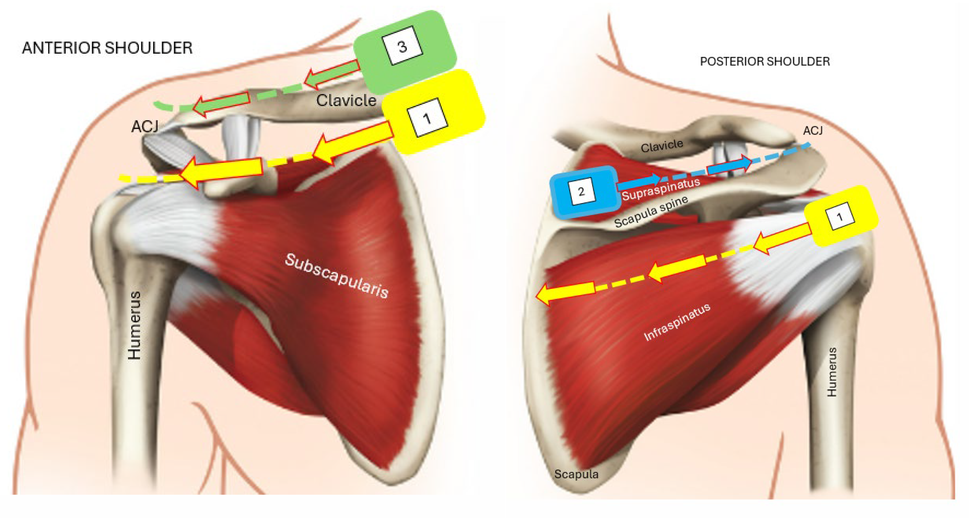
2.2. Shoulder Sonography Protocol
2.3. Registration Protocol
2.4. Mosaic Assessment Protocol (Expert Analysis of Structure Demonstration)
2.5. Mosaic Assessment Protocol (Quantitative Analysis)
3. Results
3.1. Registration and Sonography Protocols

| Element | Result | Findings |
|---|---|---|
| Time | 25 min | |
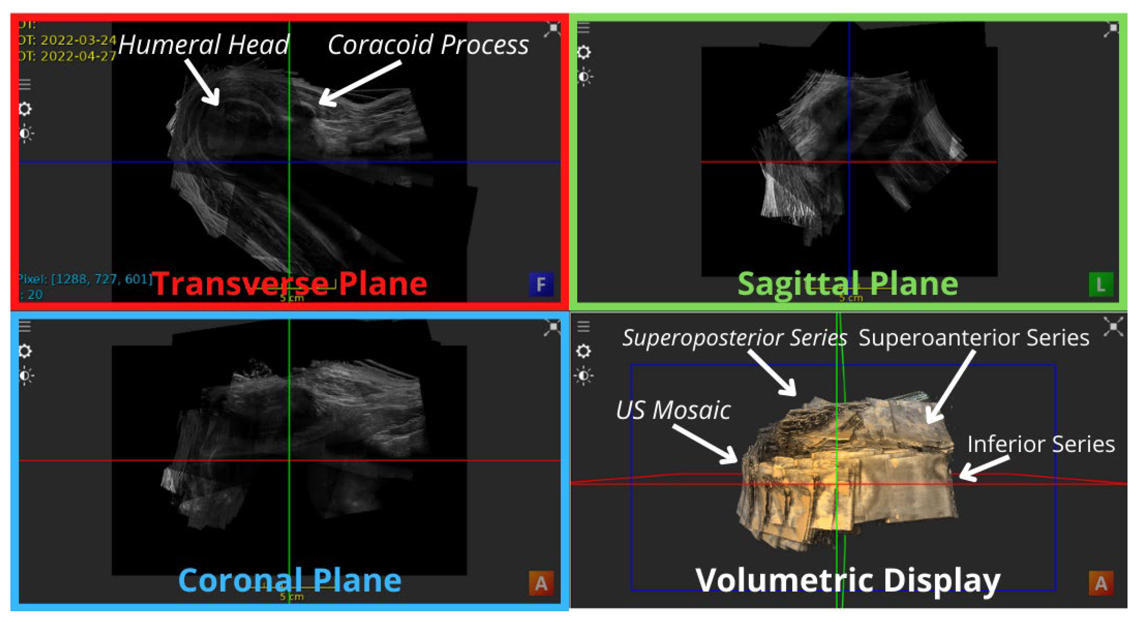
| Mosaic coverage | The whole rotator cuff region | Excluding a minor gap at the superolateral aspect of the shoulder, directly inferior to the ACJ, unobservable in the anteriror view of Figure 3 and Figure 4, yet mildly higlighted in the superolateral view of Figure 5. |
| Number of registered volumes | 53 3D contiguous volumes | Figure 3 shows the anterior view of the US mosaic. |
| Bones detected | Series 1, 2 and 3 detected the humerus, clavicle and scapula, respectively | The clavicle was not demonstrated in the inferior shoulder, except for the first volume. |
| Patient movements | Minor for soft tissue Did not notably affect bony anatomy | Perfect alignment of soft tissue, especially inter-series, was challenging. Minor tissue displacements were detected live on the US system’s display during the scans. |
| Registration (Anatomy) | Priority was offered to bones over soft tissue | In many cases, when registration of the bone anatomy was achieved, the soft tissue alignment wasn’t perfect and vice versa. |
| Registration (Regions) | Registering anterior images was significantly easier than posterior counterparts | Due to easily identifiable bony structures. Inferolateral volumes were most challenging for relatively poorer probe contact and presence of anatomical landmarks. |
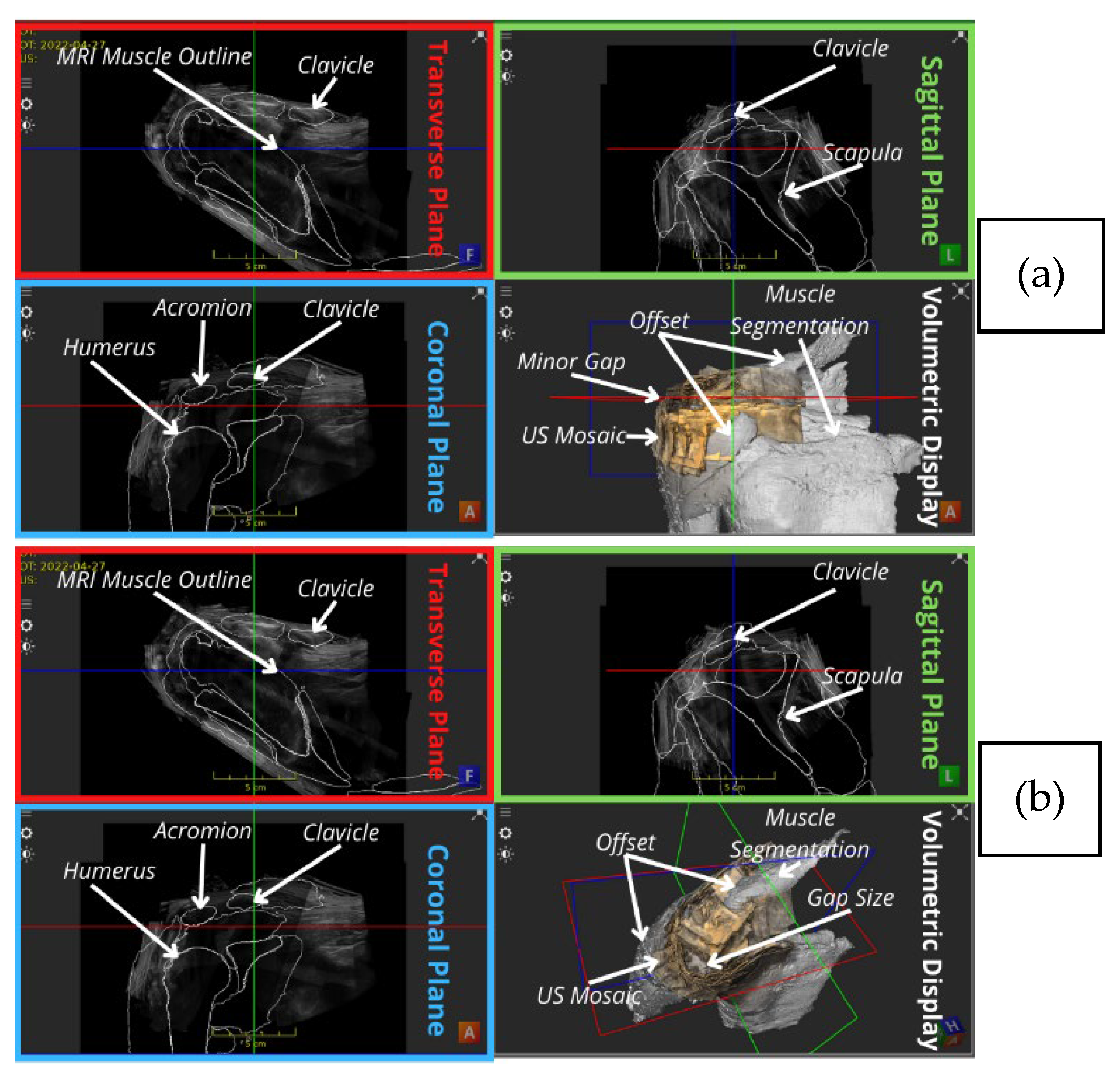
| MRI bony overlay (Positive observations) | Improved visual demonstration of bony anatomy | Visual inspection of Figure 3 shows a satisfying alignment of the humerus across all planes and the acromion in the sagittal plane. |
| MRI bony overlay (Negative observations) | Slight malalignments between US mosaic and the MRI bones mostly in form of rotational offsets | When scrolling through the transverse plane, the coracoid appears in the US mosaic before it is outlined in the corresponding MRI, and the opposite occurs in the coronal demonstration of part of the clavicle as indicated by the arrows in Figure 4. |
| MRI muscle overlay | The offset was more eminent as shown in Figure 5. | Discontinuities observed between the US mosaic and MRI muscle overlay because of mild soft tissue and muscle plane distortion caused by positional variation of the subject between modalities. |
3.2. Mosaic Assessment (Expert Analysis of Structure Demonstration)
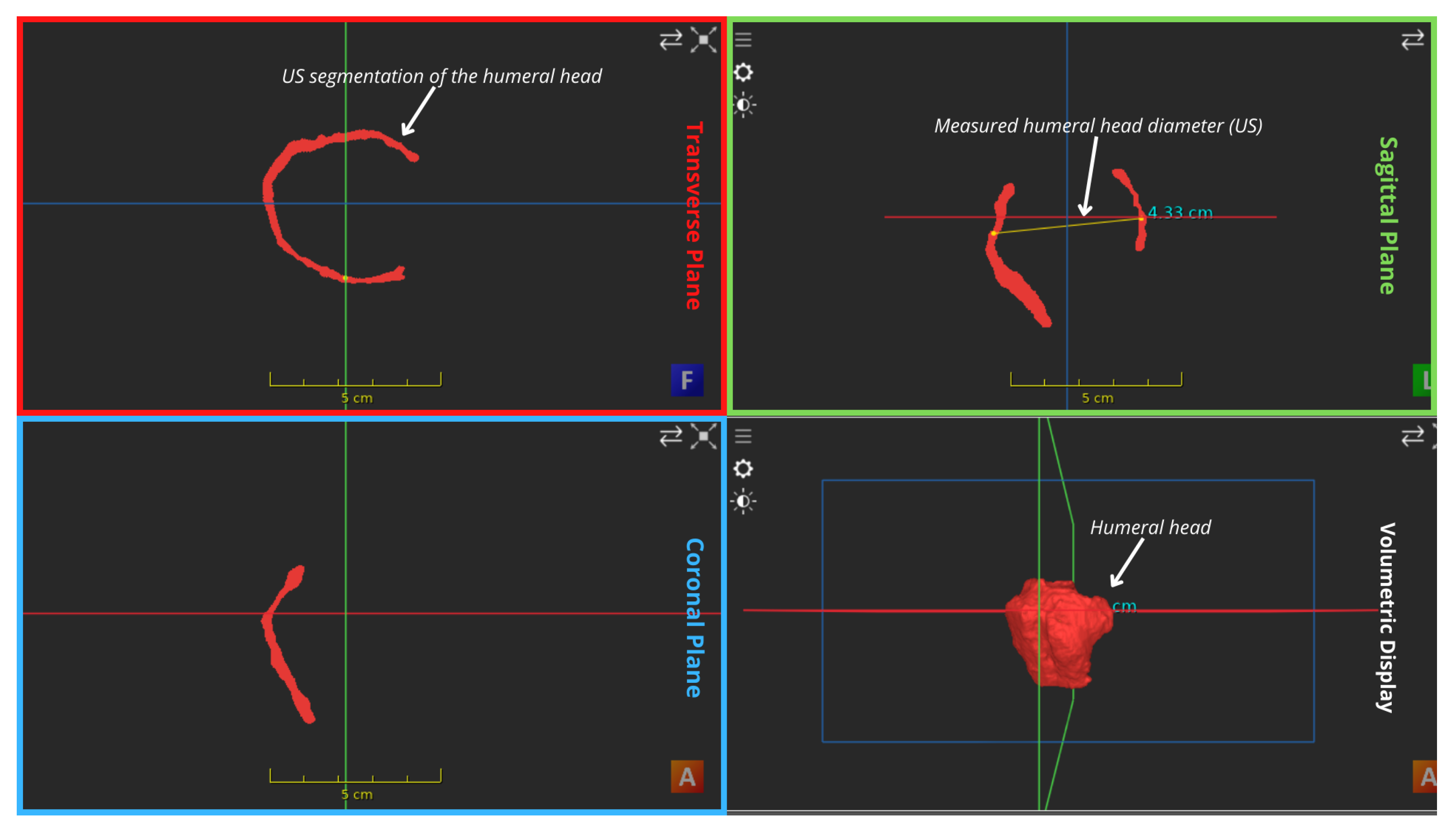
3.3. Mosaic Assessment (Quantitative Analysis)
4. Discussion
5. Conclusions
Author Contributions
Funding
Institutional Review Board Statement
Informed Consent Statement
Data Availability Statement
Acknowledgments
Conflicts of Interest
Appendix A
| Structure Demonstration | |||
|---|---|---|---|
| Anatomy | US Image | US/MRI Bone Image | US/MRI Muscle Image |
| Bony Anatomy | |||
| ACJ |  |  |  |
| ACHD |  |  |  |
| Bicipital Groove |  |  |  |
| Spinoglenoid Notch |  |  |  |
| Bony Surface: Clavicle |  |  |  |
| Bony Surface: Humerus |  |  |  |
| Bony Surface: Scapula |  |  |  |
| Tendons | |||
| Biceps |  |  |  |
| Subscapularis |  |  |  |
| Supraspinatus |  |  |  |
| Infraspinatus |  |  |  |
| Teres Minor |  |  |  |
| Muscles | |||
| Infraspinatus |  |  |  |
| Teres Minor/Major |  |  |  |
| Supraspinatus |  |  |  |
| Trapezius |  |  |  |
| Deltoid |  |  |  |
| Subacromial/subdeltoid Bursa |  |  |  |
| Ligaments | |||
| Coracoacromial |  |  |  |
| Coracohumeral |  |  |  |
| Glenohumeral |  |  |  |
| Other | |||
| Post-Glenohumeral Labrum/Joint |  |  |  |


References
- Liu, Y.; Cheng, H.D.; Huang, J.; Zhang, Y.; Tang, X.; Tian, J. An Effective Non-rigid Registration Approach for Ultrasound Image Based On “Demons” Algorithm. J. Digit. Imaging 2012, 26, 521–529. [Google Scholar] [CrossRef][Green Version]
- Kompella, G.; Singarayan, J.; Antico, M.; Sasazawa, F.; Yu, T.; Ram, K.; Pandey, A.K.; Fontanarosa, D.; Sivaprakasam, M. Automatic 3D MRI-Ultrasound Registration for Image Guided Arthroscopy. Appl. Sci. 2022, 12, 5488. [Google Scholar] [CrossRef]
- Harris, E.; Fontanarosa, D.; Camps, S.; Verhaegen, F. Institute of Physics Modern Applications of 3D/4D Ultrasound Imaging in Radiotherapy; Emma, H., Davide, F., Saskia, C., Frank, V., Eds.; IOP Publishing: London, UK, 2021; ISBN 0-7503-2551-8. [Google Scholar]
- WHO Study Group on Training in Diagnostic Ultrasound: Essentials Pennsylvania) P. and S. (1996: P.; Organization W.H. Training in Diagnostic Ultrasound: Essentials, Principles and Standards: Report of a WHO Study Group 1998. Available online: https://apps.who.int/iris/handle/10665/42093 (accessed on 25 May 2022).
- Brattain, L.J.; Telfer, B.A.; Dhyani, M.; Grajo, J.R.; Samir, A.E. Machine Learning for Medical Ultrasound: Status, Methods, and Future Opportunities. Abdom. Radiol. 2018, 43, 786. [Google Scholar] [CrossRef] [PubMed]
- Rix, A.; Lederle, W.; Theek, B.; Lammers, T.; Moonen, C.; Schmitz, G.; Kiessling, F. Advanced Ultrasound Technologies for Diagnosis and Therapy. J. Nucl. Med. 2018, 59, 740–746. [Google Scholar] [CrossRef] [PubMed]
- Bushberg, J.T. The Essential Physics of Medical Imaging; Lippincott Williams & Wilkins: Philadelphia, PA, USA, 2002; p. 933. [Google Scholar] [CrossRef]
- Singh, J.P. Shoulder ultrasound: What you need to know. Indian J. Radiol. Imaging 2012, 22, 284–292. [Google Scholar] [CrossRef] [PubMed]
- Jacobson, J.A. Shoulder US: Anatomy, Technique, and Scanning Pitfalls. Radiology 2011, 260, 6–16. [Google Scholar] [CrossRef] [PubMed]
- Beggs, I.; Stefano Bianchi, U.; Angel Bueno, S.; Michel Cohen, S.; Michel Court-Payen, F.; Andrew Grainger, D.; Franz Kainberger, U.; Andrea Klauser, A.; Carlo Martinoli, A.; Eugene McNally, I.; et al. Musculoskeletal Ultrasound Technical Guidelines I. Shoulder. Eur. Soc. Musculoskelet. Radiol. 2017, 1, 1–8. [Google Scholar]
- Farina, R.; Sparano, A. Errors in sonography. In Errors in Radiology; Springer: Milan, Italy, 2012; pp. 79–85. [Google Scholar] [CrossRef]
- Duric, N.; Littrup, P. Breast Ultrasound Tomography. In Breast Imaging; InTech Open: London, UK, 2017. [Google Scholar] [CrossRef]
- Evans, K.; Roll, S.; Baker, J. Work-related musculoskeletal disorders (WRMSD) among registered diagnostic medical sonographers and vascular technologists: A representative sample. J. Diagnostic Med. Sonogr. 2009, 25, 287–299. [Google Scholar] [CrossRef]
- Volpato, V.; Mor-Avi, V.; Narang, A.; Prater, D.; Gonçalves, A.; Tamborini, G.; Fusini, L.; Pepi, M.; Patel, A.R.; Lang, R.M. Automated, machine learning-based, 3D echocardiographic quantification of left ventricular mass. Echocardiography 2019, 36, 312–319. [Google Scholar] [CrossRef]
- Pinto, A.; Pinto, F.; Faggian, A.; Rubini, G.; Caranci, F.; Macarini, L.; Genovese, E.A.; Brunese, L. Sources of error in emergency ultrasonography. Crit. Ultrasound J. 2013, 5, S1. [Google Scholar] [CrossRef]
- Poon, T.C.; Rohling, R.N. Three-dimensional extended field-of-view ultrasound. Ultrasound Med. Biol. 2006, 32, 357–369. [Google Scholar] [CrossRef]
- Yao, C.; Simpson, J.; Jansen, C.H.P.; King, A.; Penney Cheng Yao, G.; Simpson, J.M.; King, A.P.; Penney, G.P. Spatial compounding of large sets of 3D echocardiography images. In Medical Imaging 2009: Ultrasonic Imaging and Signal Processing; SPIE: Bellingham, WA, USA, 2009; Volume 7265, pp. 358–365. [Google Scholar] [CrossRef]
- Antico, M.; Sasazawa, F.; Takeda, Y.; Jaiprakash, A.T.; Wille, M.L.; Pandey, A.K.; Crawford, R.; Fontanarosa, D. 4D Ultrasound-Based Knee Joint Atlas for Robotic Knee Arthroscopy: A Feasibility Study. IEEE Access 2020, 8, 146331–146341. [Google Scholar] [CrossRef]
- Zettinig, O.; Fuerst, B.; Kojcev, R.; Esposito, M.; Salehi, M.; Wein, W.; Rackerseder, J.; Sinibaldi, E.; Frisch, B.; Navab, N. Toward real-time 3D ultrasound registration-based visual servoing for interventional navigation. In Proceedings of the 2016 IEEE International Conference on Robotics and Automation (ICRA), Stockholm, Sweden, 16–21 May 2016; pp. 945–950. [Google Scholar] [CrossRef]
- Hacihaliloglu, I.; Wilson, D.R.; Gilbart, M.; Hunt, M.A.; Abolmaesumi, P. Non-iterative partial view 3D ultrasound to CT registration in ultrasound-guided computer-assisted orthopedic surgery. Int. J. Comput. Assist. Radiol. Surg. 2012, 8, 157–168. [Google Scholar] [CrossRef]
- Brendel, B.; Winter, S.; Rick, A.; Stockheim, M.; Ermert, H. Bone registration with 3D CT and ultrasound data sets. Int. Congr. Ser. 2003, 1256, 426–432. [Google Scholar] [CrossRef]
- Stolka, P.J.; Henrich, D.; Tretbar, S.H.; Federspil, P.A. First 3D ultrasound scanning, planning, and execution of CT-free milling interventions with a surgical robot. In Proceedings of the 2008 30th Annual International Conference of the IEEE Engineering in Medicine and Biology Society, Vancouver, BC, Canada, 20–25 August 2008; pp. 5605–5610. [Google Scholar]
- Kristin, J.; Burggraf, M.; Mucha, D.; Malolepszy, C.; Anderssohn, S.; Schipper, J.; Klenzner, T. Automatic Registration for Navigation at the Anterior and Lateral Skull Base. Ann. Otol. Rhinol. Laryngol. 2019, 128, 894–902. [Google Scholar] [CrossRef] [PubMed]
- Goos, G.; Hartmanis, J.; Van, J.; Board, L.E.; Hutchison, D.; Kanade, T.; Kittler, J.; Kleinberg, J.M.; Kobsa, A.; Mattern, F.; et al. LNCS 7510-Medical Image Computing and Computer-Assisted Intervention. In Proceedings of the MICCAI 2012: 15th International Conference, Nice, France, 1–5 October 2012. [Google Scholar]
- Schneider, R.J.; Perrin, D.P.; Vasilyev, N.V.; Marx, G.R.; Del Nido, P.J.; Howe, R.D. Real-time image-based rigid registration of three-dimensional ultrasound. Med. Image Anal. 2012, 16, 402–414. [Google Scholar] [CrossRef] [PubMed]
- Figl, M.; Hoffmann, R.; Kaar, M.; Hummel, J. Deformable registration of 3D ultrasound volumes using automatic landmark generation. PLoS ONE 2019, 14, e0213004. [Google Scholar] [CrossRef] [PubMed]
- Foroughi, P.; Abolmaesumi, P. Elastic registration of 3D ultrasound images. Med. Image Comput. Comput. Assist. Interv. 2005, 8, 83–90. [Google Scholar] [CrossRef] [PubMed]
- Zikic, D.; Wein, W.; Khamene, A.; Clevert, D.A.; Navab, N. Fast Deformable Registration of 3D-Ultrasound Data Using a Variational Approach. Lect Notes Comput Sci (including Subser Lect Notes Artif Intell Lect Notes Bioinformatics). In Proceedings of the Medical Image Computing and Computer-Assisted Intervention—MICCAI, Copenhagen, Denmark, 1–6 October 2006; pp. 915–923. Available online: https://link.springer.com/chapter/10.1007/11866565_112 (accessed on 25 May 2022).
- Lavaill, M.; Martelli, S.; Gilliland, L.; Gupta, A.; Kerr, G.; Pivonka, P. The effects of anatomical errors on shoulder kinematics computed using multi-body models. Biomech. Model. Mechanobiol. 2022, 21, 1561–1572. [Google Scholar] [CrossRef] [PubMed]
- Che, C.; Mathai, T.S.; Galeotti, J. Ultrasound registration: A review. Methods 2017, 115, 128–143. [Google Scholar] [CrossRef] [PubMed]
- JASP Team. Computer Program.2023. JASP 0.18. Available online: https://jasp-stats.org/ (accessed on 25 September 2023).
- Ranganathan, P.; Pramesh, C.; Aggarwal, R. Common pitfalls in statistical analysis: Measures of agreement. Perspect. Clin. Res. 2017, 8, 187. [Google Scholar] [CrossRef] [PubMed]
- McNally, E.G. Practical Musculoskeletal Ultrasound, 2nd ed.; Elsevier Health Sciences: London, UK, 2014; ISBN 1-4557-7404-9. [Google Scholar]
- Welk, L.A.; Adler, R.S. Case report 725. Skeletal Radiol. 1992, 21, 198–200. [Google Scholar] [CrossRef] [PubMed][Green Version]
- Wong, M.; Kiel, J. Anatomy, Shoulder and Upper Limb, Acromioclavicular Joint; Ochsner Clinical School, University of Florida College of Medicine-Jacksonville, Ed.; StatPearls Publishing: Treasure Island, FL, USA, 2021; Available online: https://www.ncbi.nlm.nih.gov/books/NBK499858/#!po=15.6250 (accessed on 25 September 2023).


| Series | Region | Starting Landmark | Ending Landmark | Probe Trajectory | Number of Volumes |
|---|---|---|---|---|---|
| Series 1 (Part 1) | Anteroinferior | Medial-Clavicle | ACJ | Medial to Lateral | 16 |
| Series 1 (Part 2) | Posteroinferior | Medial-Scapula Spine | Lateral to Medial | 15 | |
| Series 2 | Posterosuperior | Scapula | ACJ | Medial to Lateral | 11 |
| Series 3 | Anterosuperior | Medial Clavicle | ACJ | Medial to Lateral | 11 |
| Protocol Step | Description | Rationale |
|---|---|---|
| US volume Setup | The 53 acquired rotator cuff volumes were imported into ImFusion (ImFusion GmbH, Munich, Germany) in a common-world coordinate frame. | |
| Pairwise Registration | Common features (anatomical landmarks, mainly bones) in consecutive volume pairs were manually identified and matched by an operator based on their clinical knowledge. | A similar approach was successfully employed by [18] for 3D US images of the knee. Attempt to improve on [16]’s simple compounding technique. |
| Transformation | The first volume in each pair was fixed while the second was rigidly transformed (translated and rotated) with respect to it to align common features. Figure 2 shows an example of manual registration of a pair of consecutive volumes using common features. | Recommended by [30] for 3D and 4D US registration of bony anatomy with potential for submillimeter accuracy since bones are non-deformable structures. Non-rigid transformation was avoided as it may degrade image quality, and it is a very complex and potentially error-prone operation [17]. |
| Quadruple-wise Registration | After aligning 2 volume pairs, all 4 neighbouring volumes were reviewed. Necessary transformation adjustments were performed by linking the adjusted volume to all following volumes to update their relative transformations. | To check for overall consistency and identify more anatomical structures to verify volume overlays. |
| Preceding steps were repeated for the whole series | ||
| Volume Compounding | Registered volumes were compounded (merged) in sets of 4 using maximum volume compounding, ultimately resulting in a single compounded volume for the whole series. | This compounding method was used as it offers an improved contrast in the US volumes which is often essential for distinguishing and assessing MSK structures as reported by [17]. |
| Preceding step was performed 3 times, once for each series | ||
| Superior Series Compounding | Compounded posterosuperior and anterosuperior volumes were registered to each other, forming a superior shoulder volume data set. | Finding the initial configuration of the superior and inferior shoulder series was challenging. |
| MRI Setup | The 2 volume data sets and the MRI were both imported into ImFusion, visualizing the two modalities under a common world frame. | Comparing the position of the outlined bones and muscles in the MRI can aid in identifying the US structures in question. |
| US-MRI Registration | The bony structures in each of the 2 US volume data sets were registered to the contours of their corresponding bone segmentations of the MRI. | MRI-based bone segmentations offered a starting point for the registration of the 2 noncontiguous volume data sets (inferior and superior shoulder). |
| Full shoulder Series Registration and Compounding | After the initial registration, the bone and soft tissue anatomy in the 2 US volume data sets were registered with each other, following the previous steps. | |
| Procedure was revised by 3 different operators including the sonographer | ||
| Sonographer 1 Assessment | ||||||
|---|---|---|---|---|---|---|
| Anatomy | US Grade | US Comments | MRI Grade | MRI Comments | Muscle Grade | Muscle Comments |
| Bony Anatomy | ||||||
| Acromioclavicular (ACJ) | 3 | Partially Demonstrated | 1 | Anteroposterior alignment of the ACJ = 1 | Did not influence grades | |
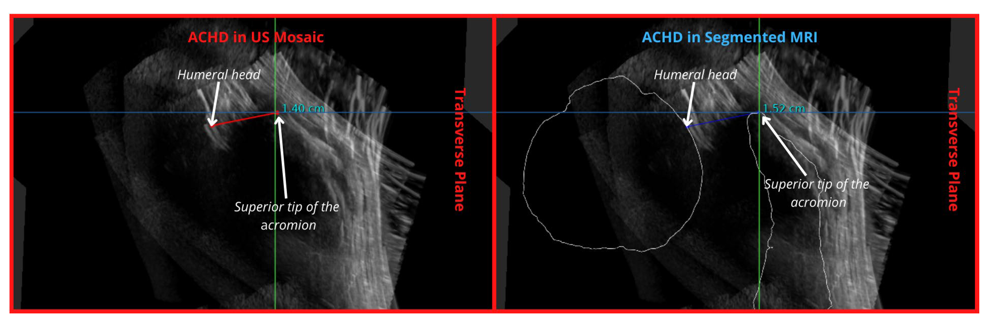
| Acromiohumeral Distance (ACHD) | 3 | Partially Demonstrated | 1 | Well demonstrated | ||
| Bicipital Groove | 2 | Adequately Demonstrated | 2 | Adequately Demonstrated | ||
| Spinoglenoid Notch | 4 | Region Seen | 4 | AP: seen Sup-inf: not seen | ||
| Bony Surface (Humerus (H), Scapula (S) and Clavicle (C)) | 4 C:4 H:2 S:4 | Region Seen | 3 C: 3 H:1 S:3 | Clavicle: limited length seen Humerus: some humeral surface malalignment Scapula: lateral aspect of spine obstructed by overlying anatomy | ||
| Tendons | ||||||
| Biceps | 2 | Adequately Demonstrated | 2 | Better seen if arm rotated externally | Did not influence grades | |
| Subscapularis | 3 | Partially Demonstrated | 3 | Some bony artefact shadow is inevitable | ||
| Supraspinatus | 3 | Partially Demonstrated | 3 | Better seen with arm in internal rotation | ||
| Infraspinatus | 3 | Partially Demonstrated | 3 | Difficult to assess/distinguish from IST in this position. Better seen with arm in internal rotation | ||
| Teres Minor | 3 | Partially Demonstrated | 3 | Better seen if arm rotated internally | ||
| Muscles | ||||||
| Infraspinatus | 3 | Partially Demonstrated | 3 | Difficult to say whether the entire muscle is included—extensive muscle | Did not influence grades | |
| Teres Minor/Major | 4 | Region seen (Partially) | 4 | Difficult to delineate from IS muscle | ||
| Supraspinatus | 1 | Well Demonstrated | 1 | |||
| Trapezius | 3 | Region Seen (Partially) | 3 | Limited section seen | ||
| Deltoid | 3 | Partially Demonstrated | 3 | Some interruption by artefacts laterally | ||
| Subacromial/subdeltoid Bursa | 2 | Adequately Demonstrated | 2 | Some regions of bony shadowing/artefact | ||
| Ligaments | ||||||
| Coracoacromial (CAL) | 4 | Region seen | 4 | Best demonstrated ligament | Did not influence grades | |
| Coracohumeral (CHL) | 4 | Region seen | 4 | The region around the bicipital groove | ||
| Glenohumeral (GHL) | 4 | Region seen | 4 | Best seen with arm in a different position | ||
| Other | ||||||
| Post-Glenohumeral Labrum/Joint | 4 | Region seen | 4 | Better seen with arm in a different position | Did not influence grades | |
| Sonographer 2 Assessment | ||||||
|---|---|---|---|---|---|---|
| Anatomy | US Grade | US Comments | MRI Grade | MRI Comments | Muscle Grade | Muscle Comments |
| Bony Anatomy | ||||||
| ACJ | 2 | Best seen in A | 2 | Bone contour easily seen | 2 | |
| ACHD | 3 | Humeral head not continuous at region of measurement | 1 | Easily measured with MRI bone outline | 1 | |
| Bicipital Groove | 3 | Seen best on F slice | 3 | Bone does not line up with US groove. US humerus is more internally rotated | 3 | |
| Spinoglenoid Notch | 3 | 3 | Same to no improvement | 3 | More confusing to find | |
| Bony Surface (Humerus, Scapula and Clavicle) | 3 | Not aligned so difficult to see Humerus neck-3 Humeral head-3 Scapula Acromium-3 Scapula Coracoid-3 Spine of Scap-3 Clavicle-4 | 3 | Mild non-alignment of coracoids Humerus neck-2 Humeral head-3 Scapula Acromium-3 Scapula Coracoid-2 Spine of Scap-3 Clavicle-4 | 3 | Some are more difficult to find due to the overlay of all the muscles Humerus neck-2 Humeral head-3 Scapula Acromium-3 Scapula Coracoid-3 Spine of Scap-2 Clavicle-4 |
| Tendons | ||||||
| Biceps | 4 | Poorly seen. | 4 | Axial/transverse in groove, but not longitudinal | 3 | Easier to identify, but not adequately seen |
| Subscapularis | 3 | Central aspect seen best, limited assessment of footplate | 2 | Humerus rotation slightly limits alignment, otherwise good. | 2 | More difficult with muscle overlay, but still visible |
| Supraspinatus | 4 | Poorly seen | 3 | Definitely need the bones to help identify region | 3 | Easiest, but still not adequately seen |
| Infraspinatus | 5 | Not identified. | 3 | Massive improvement with bones | 3 | More difficult with bones |
| Teres Minor | 5 | Not identified. | 5 | Not identified | 5 | |
| Muscles | ||||||
| Infraspinatus | 4 | 3 | 3 | |||
| Teres Minor/Major | 5 | 5 | Not identified | 4 | ||
| Supraspinatus | 3 | 2 | Definitely easier | 2 | ||
| Trapezius | 3 | 3 | No change | 3 | ||
| Deltoid | 4 | 4 | 3 | More visible, not fully | ||
| Subacromial/subdeltoid Bursa | 2 | 2 | No change | 2 | ||
| Ligaments | ||||||
| CAL | 3 | 3 | Malalignment of coracoid | 3 | More difficult to find with bone overlay | |
| CHL | 5 | Not identified | 5 | 5 | ||
| GHL | 5 | Not identified | 5 | 5 | ||
| Other | ||||||
| Post-Glenohumeral Labrum/Joint | 5 | Not identified | 5 | 5 | ||
| 95% CI | ||||
|---|---|---|---|---|
| Ratings | Weighted Kappa | SE | Lower | Upper |
| Average kappa | 0.701 | |||
| SONOGRAPHER 1-SONOGRAPHER 2 | 0.701 | 0.090 | 0.526 | 0.877 |
| Mean Values (mm) | Transverse Plane | Sagittal Plane | Coronal Plane | Overall |
|---|---|---|---|---|
| Thickness in mosaic | 2.675 | 2.481666667 | 2.755 | 2.637222 |
| Thickness in a single volume | 1.686666667 | 1.758333333 | 2.52 | 1.988333 |
| Reconstruction Error (Thickness) | 0.988333333 | 0.723333333 | 0.235 | 0.648889 |
Disclaimer/Publisher’s Note: The statements, opinions and data contained in all publications are solely those of the individual author(s) and contributor(s) and not of MDPI and/or the editor(s). MDPI and/or the editor(s) disclaim responsibility for any injury to people or property resulting from any ideas, methods, instructions or products referred to in the content. |
© 2024 by the authors. Licensee MDPI, Basel, Switzerland. This article is an open access article distributed under the terms and conditions of the Creative Commons Attribution (CC BY) license (https://creativecommons.org/licenses/by/4.0/).
Share and Cite
Sewify, A.; Antico, M.; Steffens, M.; Roots, J.; Gupta, A.; Cutbush, K.; Pivonka, P.; Fontanarosa, D. 3D Ultrasound Mosaic of the Whole Shoulder: A Feasibility Study. Appl. Sci. 2024, 14, 2152. https://doi.org/10.3390/app14052152
Sewify A, Antico M, Steffens M, Roots J, Gupta A, Cutbush K, Pivonka P, Fontanarosa D. 3D Ultrasound Mosaic of the Whole Shoulder: A Feasibility Study. Applied Sciences. 2024; 14(5):2152. https://doi.org/10.3390/app14052152
Chicago/Turabian StyleSewify, Ahmed, Maria Antico, Marian Steffens, Jacqueline Roots, Ashish Gupta, Kenneth Cutbush, Peter Pivonka, and Davide Fontanarosa. 2024. "3D Ultrasound Mosaic of the Whole Shoulder: A Feasibility Study" Applied Sciences 14, no. 5: 2152. https://doi.org/10.3390/app14052152
APA StyleSewify, A., Antico, M., Steffens, M., Roots, J., Gupta, A., Cutbush, K., Pivonka, P., & Fontanarosa, D. (2024). 3D Ultrasound Mosaic of the Whole Shoulder: A Feasibility Study. Applied Sciences, 14(5), 2152. https://doi.org/10.3390/app14052152