1. Introduction
Photovoltaic power systems are easier to operate compared with other power systems in terms of ease of operation. On the other hand, an increase in the surface area of a power plant and an increase in the number of equipment types depending on the size of the photovoltaic power plant can make it difficult to detect the type and location of a fault. Faults in photovoltaic power plants are situations that prevent or reduce production. While these malfunctions are sometimes easy to fix, sometimes it may take a long time to detect and fix them, and this may cause financial losses. To avoid these financial losses faults must be identified and categorized [
1].
It is essential to first classify the problems in order to determine the root cause before analyzing the issues that occur in photovoltaic (PV) power plants. Faults can be categorized with the use of identification. Sorting problems into categories will make it easier to identify their root causes and create solutions. Because fewer faults provide higher power output, precautions taken during commissioning and operation can save time and money. The challenges faced can be categorized using several kinds of techniques [
2]. In [
3], the challenges faced by photovoltaic power plants are categorized as follows: cost, fluctuating power production, technical issues, ecological and social impacts, and performance limitations. First, the defect must be defined to classify the faults more precisely. Any effect that reduces the output voltage of a PV power plant can be called a fault [
4]. Depending on how long a problem lasts, it might be classified as either temporary or permanent. The most widely used heads for categorizing electrical failures in PV power plants were investigated by Madeti et al. in [
4]. The alternating current (AC) side and direct current (DC) side faults are the two primary categories under which the faults were addressed in their study. In [
5], Diminish et al. categorized the faults encountered in PV power plants into three sections, including AC and DC faults as well as faults encountered during the data-gathering stage for the control system. PV power plant electrical faults, specifically earth, phase-to-phase, and PV arc faults, were analyzed in the upper headings and categorized into subgroups based on the causes of the faults within each heading in [
6]. PV panel electrical failures were modeled using MATLAB/Simulink software by Chen et al. in [
7]. Compared with previous studies, Kurukuru et al.’s [
8] approach to problems in PV power plants is distinct and comprehensive. Defects were divided into three categories: physical, electrical, and environmental. A comprehensive collection of electrical issues was created by classifying them into categories such as PV string failures and inverter faults. Subsequently, Kurukuru’s model was used to analyze the fault classification technique developed for the PV plant using the MATLAB/Simulink application [
5]. In Berghout et al.’s study [
9], machine learning techniques were used in PV power plants to identify problems. In a study by Demirel et al. [
10], using a simulation tool, a model was made for a typical PV power plant, and the model’s response to lightning strikes was investigated. Bosman et al. [
11] reported that while photovoltaic power plants have a low failure rate, the popular “Install and Forget” approach to them is incorrect. Photovoltaic power plants are susceptible to a variety of failure modes. The categorization of failures based on their types and the modeling of their potential consequences are crucial for application convenience and as a resource for academic works in the future.
In this study, difficulties encountered during the commissioning and operation of photovoltaic power plants were examined, and in this context, electrical faults were modeled in the MATLAB Simulink program. We aimed to simulate a fault that occurs in the field in MATLAB Simulink. Electrical faults in photovoltaic power plants were explained, the effects of these faults were observed using the MATLAB/Simulink model, and the results obtained were compared with the results obtained in other studies.
2. Materials and Methods
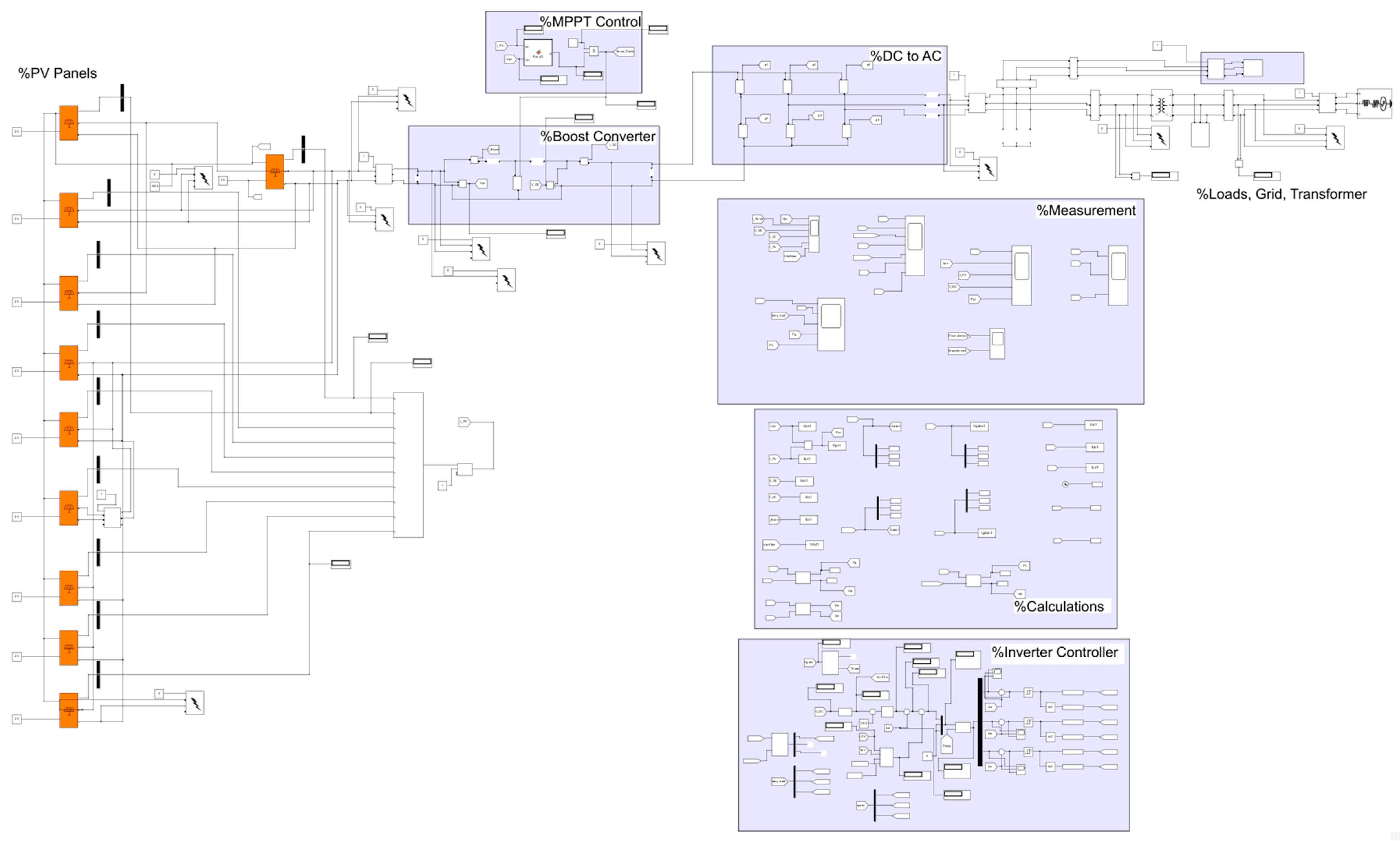
In this study, a grid-connected solar power plant modeled in the MATLAB Simulink program and its electrical faults are examined. In [
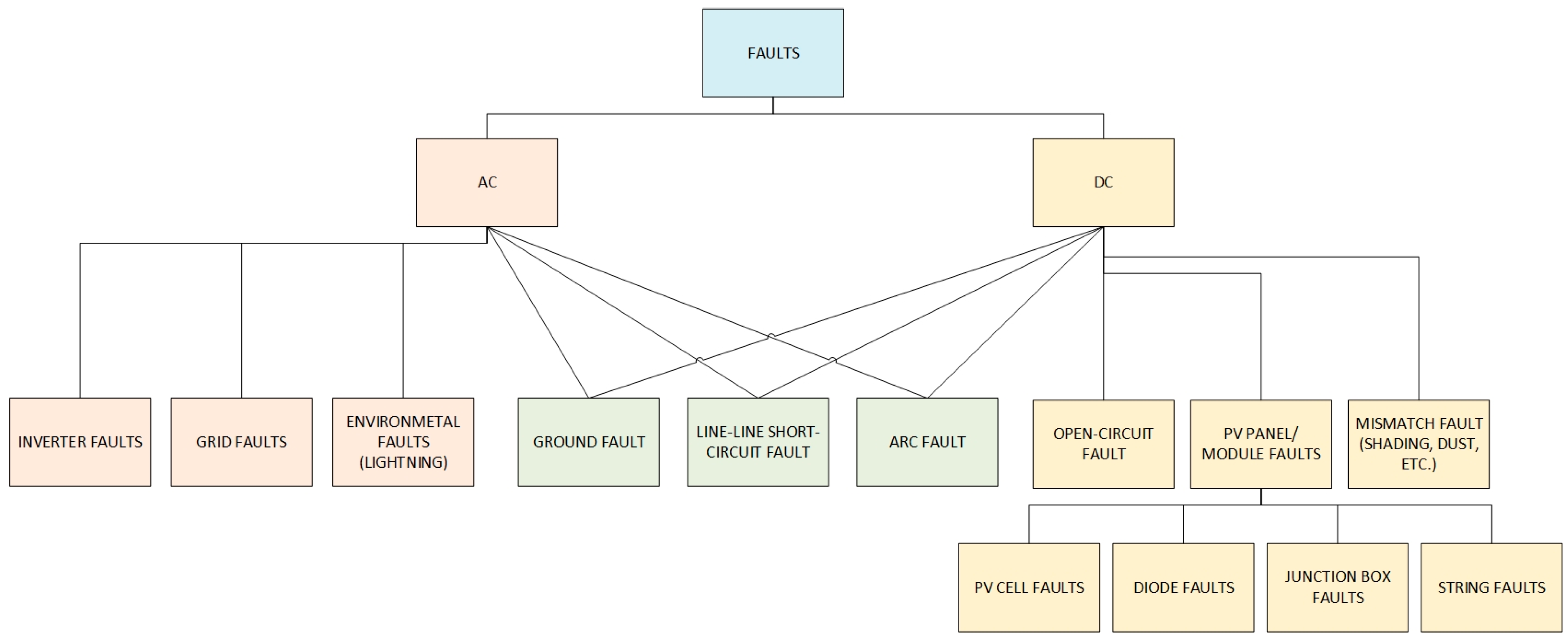
12], a fault is described as, “an abnormal condition that may cause a reduction in, or loss of, the capability of a functional unit to perform a required function”. Recent years have seen a significant increase in the research area of fault classification and detection since defects in PV power plants may affect their capacity to generate electricity [
13]. Examining the most frequent failures in PV power plants is one of the most crucial steps to understanding the causes of failures and their effects. Faults can be analyzed in this context under two categories: AC side faults and DC side faults. AC side faults may arise due to problems with the power grid or inverter. There are more DC side faults than AC side faults. These include faults in the junction box, bypass diode, cell, open circuit, short circuit, arc fault, and ground fault [
1]. The classification of electrical faults in photovoltaic plants is shown in
Figure 1 in order to increase understanding and to make physical follow-up of the fault incidence zones easier. The classification is as follows:
In the case of faults occurring on the AC side, the power of the entire system may be cut off, or, as a result of the fault, only the photovoltaic system may be disconnected from the AC side and a grid outage may occur [
14,
15,
16].
Inverter faults: In case of a fault in the inverters, the AC output power decreases or goes completely to zero while the DC power remains constant [
17].
Grid faults: Grid faults include damage to components in substations, power transmission lines, and even other power plants connected to the grid, and faults such as short circuits, open circuits, and overloads. Grid faults directly affect the grid connection of photovoltaic power plants. Grid faults may disrupt the synchronization situation or cause the photovoltaic power plant to be disconnected from the grid due to low voltage [
17,
18].
Ground faults: A ground fault occurs when there is contact between the line conductors and ground potential. A ground fault occurs between the positive or negative conductor and the ground on the DC side, while it occurs between the phase conductors and the ground on the AC side [
8,
19].
Line–line short-circuit faults: A short circuit that occurs between two points at different voltage levels or different phase voltages is called a line–line short-circuit fault. A line–line short-circuit fault occurs between the positive and negative conductor on the DC side and occurs between the phase conductors on the AC side. In photovoltaic power plants, line-to-line short-circuit faults may occur on the AC side as a result of damage to the cable insulation due to corrosion, physical impact, or animals, and on the DC side, short circuits in photovoltaic arrays may occur within the arrays or between two arrays [
20,
21].
Arc faults: Damage to cable insulation and improper connections at connection points are the main causes of arc faults [
21,
22].
Open-circuit faults: An open-circuit fault is a situation where the continuity of the conductor is interrupted at a certain point. This may occur due to external factors or over time due to improper and loose connections at the connection points [
4,
9,
23].
Mismatch faults: Incompatibilities in photovoltaic modules occur when a cell or a group of cells differs from other cells [
23,
24,
25].
Photovoltaic cell/panel/module/array faults: Photovoltaic cell/panel/module/array faults are named according to the equipment where the fault occurs [
26].
Diode faults: The purpose of using diodes in photovoltaic panels is to provide unidirectional current flow. Diode failures are mostly caused by incorrect connection and overheating [
19,
20,
27].
The MATLAB Simulink model is shown in
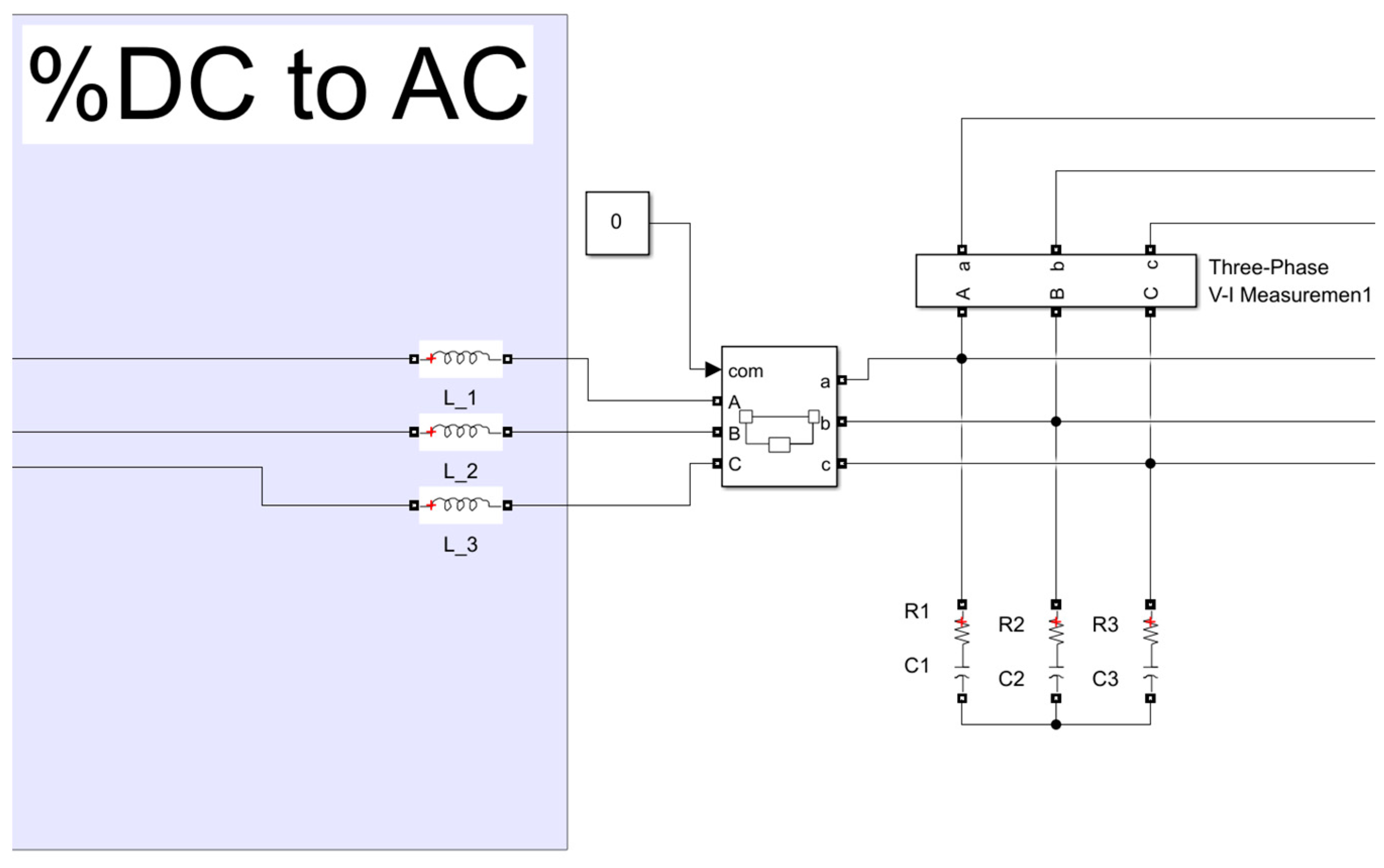
Figure 2. In this model, the central inverter is shown on the DC side, and combiner boxes are shown between these central inverters and photovoltaic panels. The power produced in photovoltaic panels is transmitted to the central inverter via collector boxes. At the inverter input, the DC current first passes through the DC-DC converter and then passes through the inverter circuit. The MPPT function is also shown in this block, which performs the inverter control functions in the inverter block and operates at the maximum power point. The AC current coming out of the inverter unit passes through the transformer and is connected to the grid.
In this study, electrical faults in photovoltaic power plants are classified according to the region where the fault occurs. In this classification system, faults are detailed according to the regions where they occur. These electrical faults are principally caused by open circuit and short circuit situations. In order to create electrical faults in the MATLAB Simulink program, open circuit and short circuit situations are created in the area where the fault occurs. Methods for creating electrical faults in photovoltaic power plants according to open circuit or short circuit situations are shown in
Table 1.
Since the photovoltaic panels and the grid connection are interrupted in the case of inverter malfunctions, an open circuit condition is created at the inverter output and the reactions on the DC and AC sides are examined.
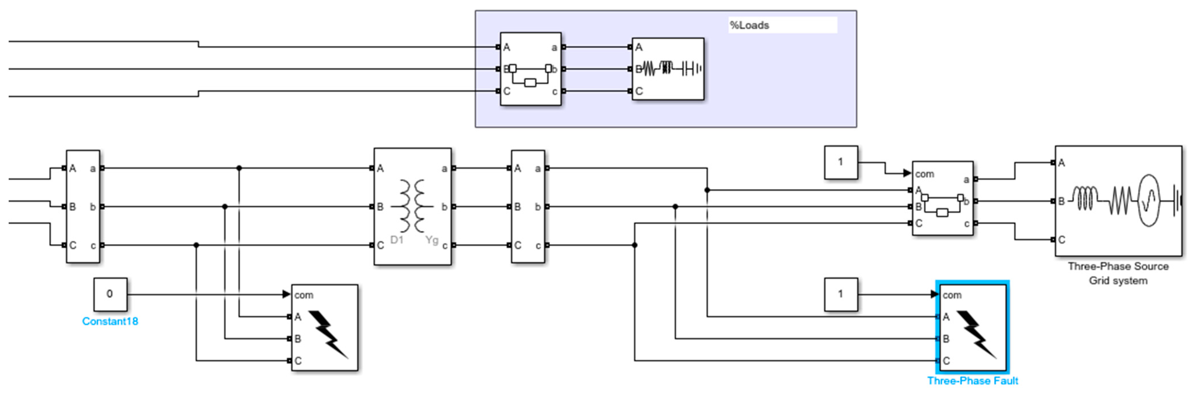
The area where the circuit breaker at the transformer output is located in the photovoltaic power plant is considered the grid connection. For this reason, short circuit and open circuit blocks are used at the transformer output to model grid-related faults in the MATLAB Simulink model of the photovoltaic power plant.
When modeling faults that are caused by environmental effects, in contrast to short circuit and open circuit situations, the amount of radiation is changed in order to show the effect of shadowing due to external effects on current and voltage.
Ground fault and line-to-line short-circuit fault conditions are produced by using the “three-phase fault” object in the MATLAB Simulink program.
To generate the open-circuit fault on the DC side, the circuit breaker object is used in the MATLAB Simulink program.
Equipment failures on the DC side are simulated by creating a short circuit situation on the DC side under the title “Photovoltaic Module Fault”.
Within the scope of this study, it is assumed that circuit protection equipment is not active so the fault condition remains. For this reason, circuit protection equipment is not included in the model.
To create fault conditions in MATLAB Simulink, certain process steps were followed to standardize fault creation. Firstly, the MATLAB Simulink program was started, and it was ensured that the simulation was working correctly. The process steps for different faults are listed below:
DC line–line short-circuit fault: The phase-to-phase short-circuit fault block connected between the photovoltaic panels and the inverter was triggered externally.
DC ground fault: The phase-ground short-circuit fault block connected between the photovoltaic panels and the inverter was triggered externally.
DC open circuit: The breaker block connected between the photovoltaic panels and the inverter was triggered from the outside to open the breaker.
Grid-sourced phase-to-phase short-circuit fault: The phase-to-phase short-circuit fault block connected between the photovoltaic power plant and the grid was triggered externally.
Grid-sourced open-circuit fault: The breaker block connected between the photovoltaic power plant and the grid was triggered from the outside to open the breaker.
Inverter fault: The breaker block connected between the inverter power output side and the transformer was triggered from the outside to open the breaker.
PV module fault: The phase-to-phase short-circuit fault block connected between the output side of one of the photovoltaic modules and the inverter was triggered externally.
Mismatch fault: The radiation information inputs of photovoltaic panels were changed.
3. Results and Discussion
In this section, the outputs of the faults created in the MATLAB Simulink program are given, and the results obtained are compared with other studies.
The modeled photovoltaic power plant is connected to the busbar of the facility at the 34.5 kV medium voltage level within a real-time facility and is subsequently connected to the grid via the grid connection point. It includes a central inverter with an installed power of 1.8 MW connected to the grid.
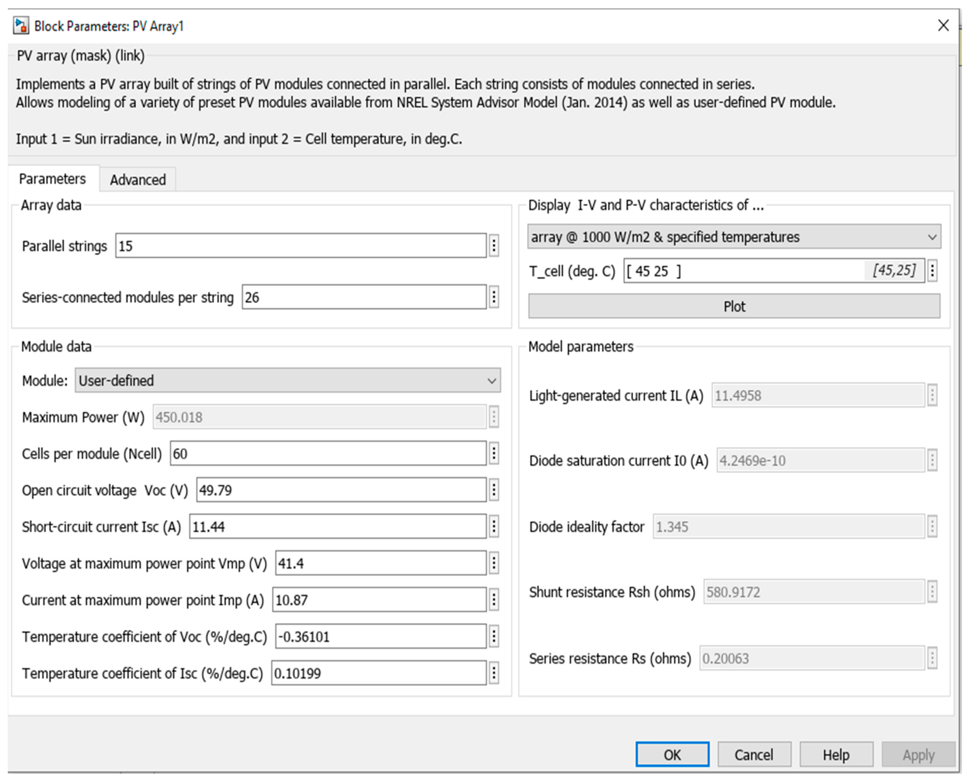
Photovoltaic cells are used in monocrystalline cell types. For each photovoltaic panel used in the photovoltaic power plant; the maximum power is 450 W, the maximum power point voltage is 41.4 V, the maximum power point current is 10.87 A, the open circuit voltage is 49.79 V, and the short circuit current is 11.44 A. There are 26 series-connected photovoltaic modules in each array and 15 parallel-connected arrays in each combiner box. A total of 10 combiner boxes are used. In this configuration, the maximum input voltage of the inverter is 1500 V DC, and the rated voltage is 1100 V DC. The output voltage of the inverter is 500 V AC. A step-up transformer with a ratio of 0.5/34.5 kV is used at the grid connection point of the inverter to transmit the inverter output voltage to the grid. While modeling fault situations, the air temperature is set to 25 °C and the radiation is set to 1000 W/m2 to keep the environmental effects constant in every failure situation and to identify the situation where power production is at maximum efficiency.
Details about photovoltaic panels are shown in
Figure 3.
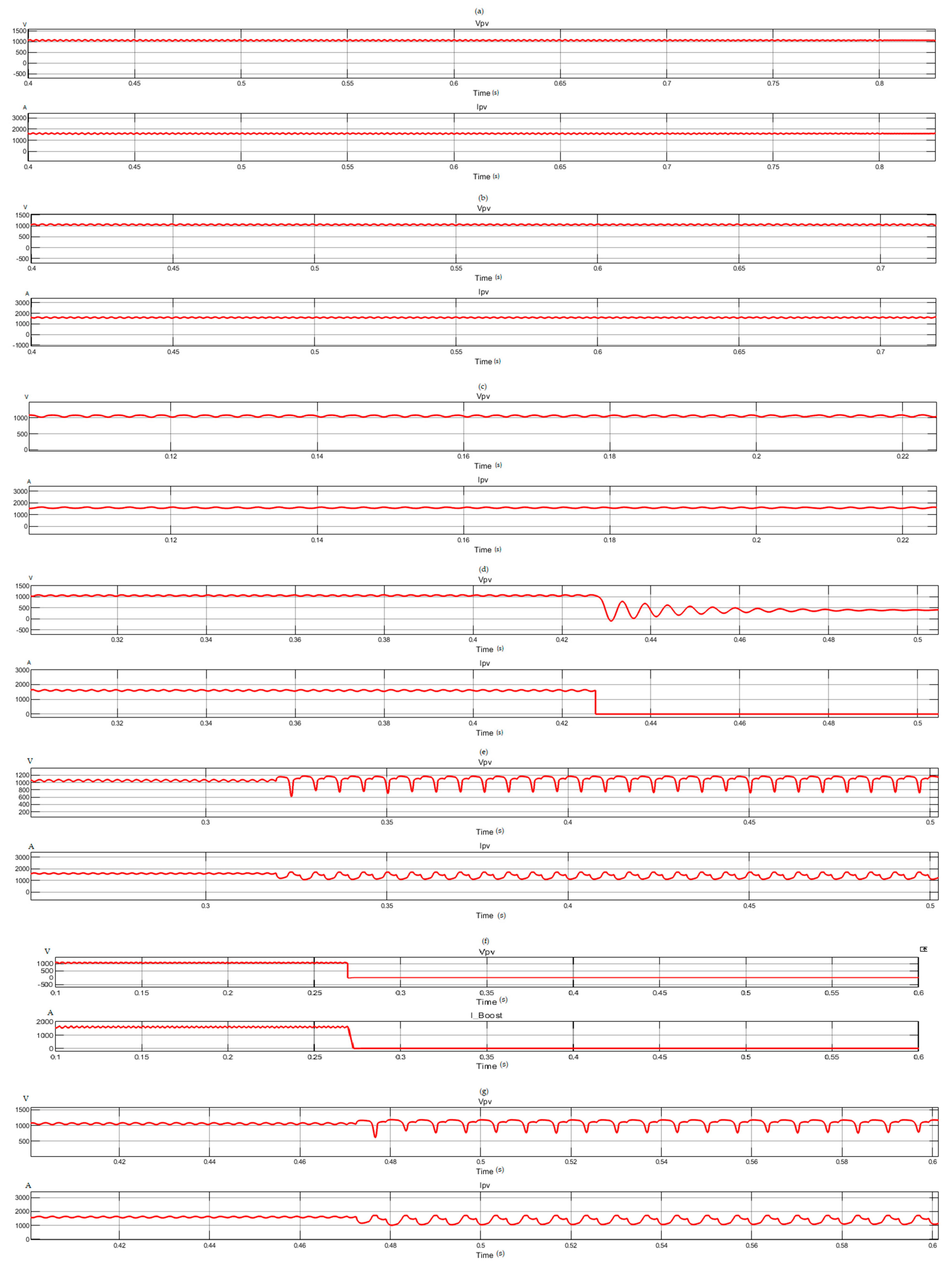
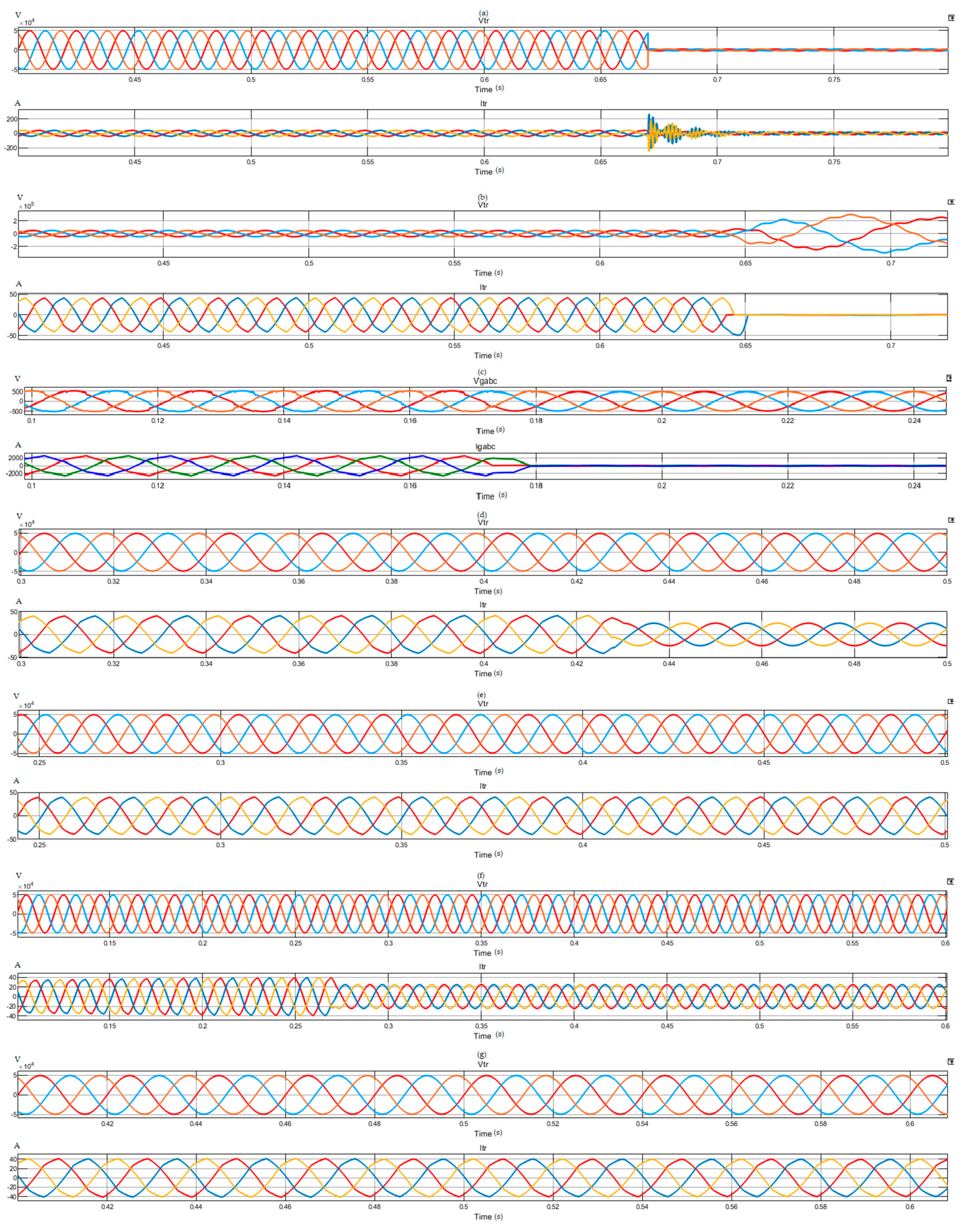
As a result of modelling the faults on MATLAB Simulink, the graphs in
Figure 4 and
Figure 5 were obtained.
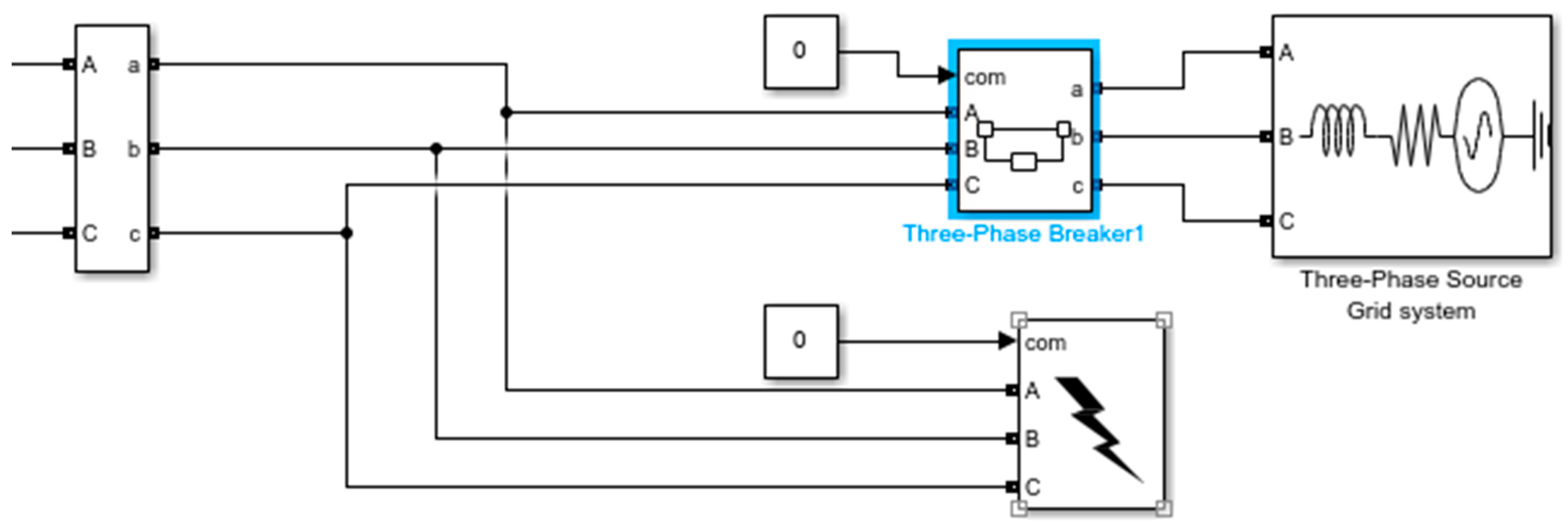
3.1. Grid-Sourced Phase–Phase Short-Circuit Fault
For a phase–phase short-circuit fault to occur at the mains output on the AC side, a fault condition is created by triggering the fault block selected in
Figure 6. As a result of the fault, the effective value of the voltage on the AC side decreased from 34.5 kV to 0 kV, and the effective value of the current instantly increased from 29 A to 188 A. In
Figure 4 and
Figure 5, it can be seen that a phase-to-phase short circuit occurring at the grid connection point directly affects the transformer output voltage but does not affect the DC current or voltage read from the output of the photovoltaic panels.
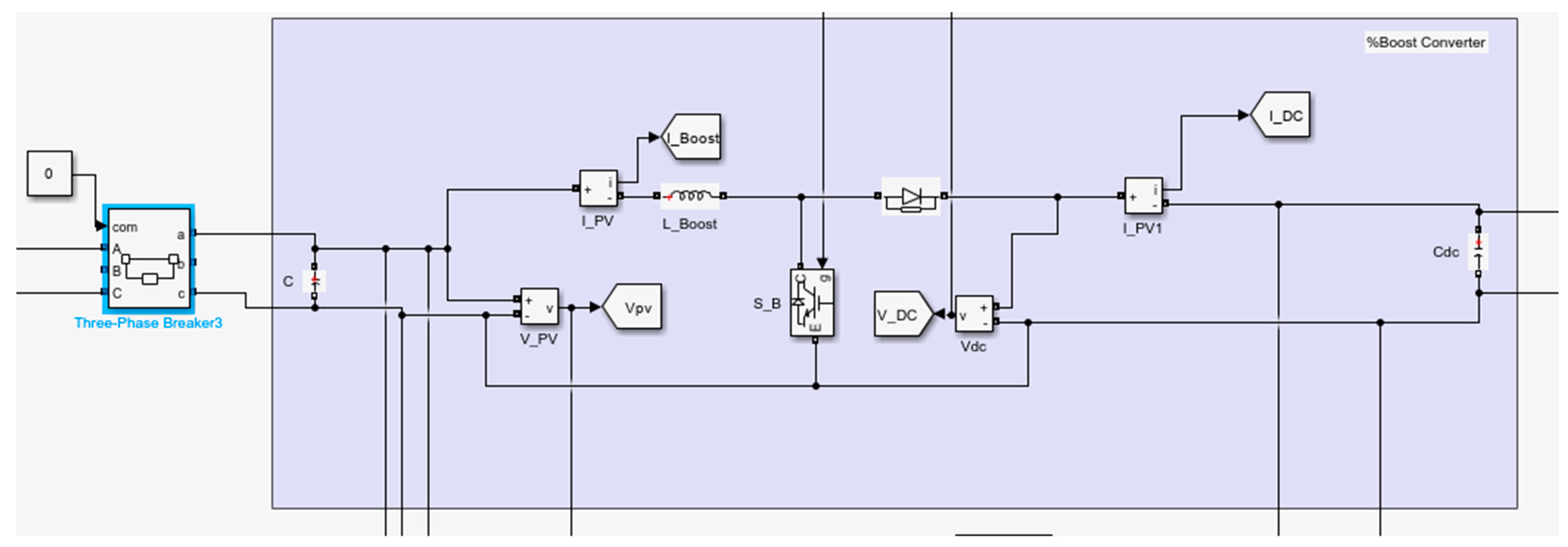
3.2. Grid-Sourced Open-Circuit Fault
In order to create an open-circuit fault at the mains output on the AC side, the circuit breaker in
Figure 7 is marked as open from the outside. As can be seen from the graphs in
Figure 4 and
Figure 5, after the fault occurs, in the measurement taken by the transformer grid side, the transformer output current is reset to zero as soon as an open circuit condition occurs, the effective value of the output voltage increases from 34.5 to 212 kV, and the sine wave shape is distorted. It can be seen that the DC current and voltage read from the output of the photovoltaic panels are not affected.
3.3. Inverter Fault
In order to create an open-circuit fault at the inverter output on the AC side, the breaker in
Figure 8 is triggered as open externally. After the fault occurs, it can be seen from the graphs in
Figure 4 and
Figure 5 that the current and power values on the AC side decrease to zero while the voltage values remain constant despite a short-term, low-amplitude distortion in sinusoidal form. On the DC side, no effect of this fault can be observed.
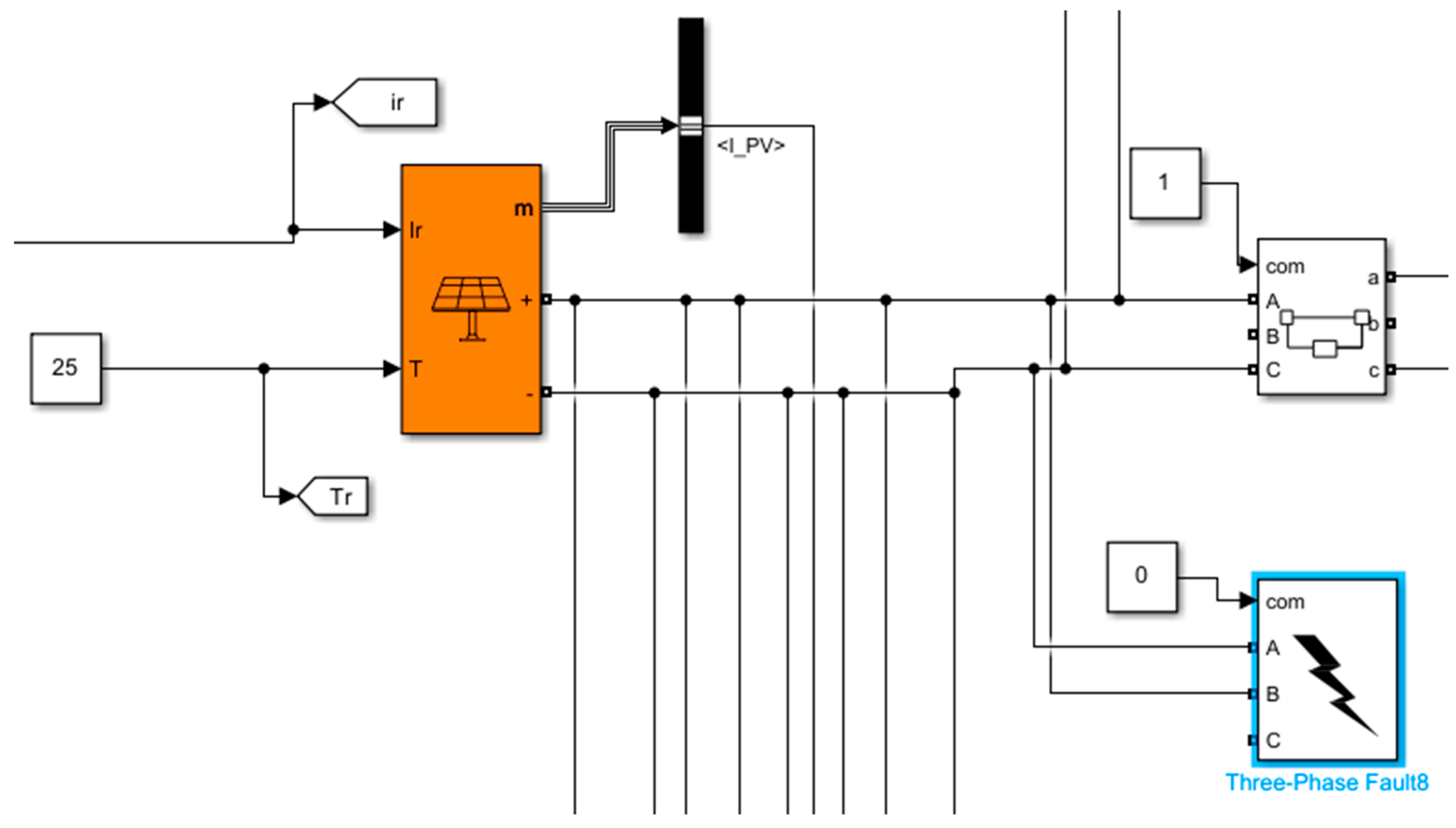
3.4. DC Open-Circuit Fault
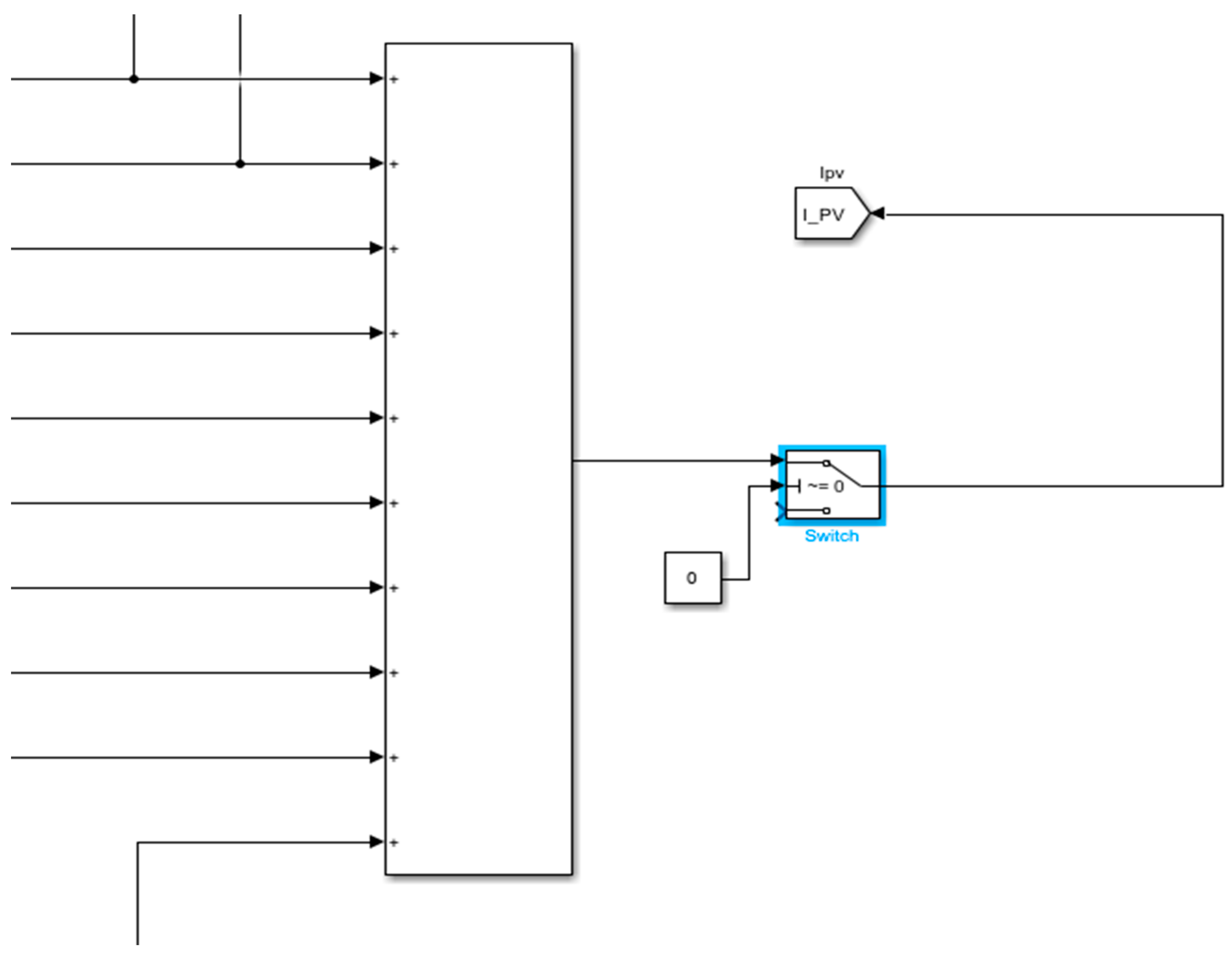
In order to create an open-circuit fault on the DC side, the breaker in
Figure 9 is triggered as open externally. Since the DC current is to be used for calculations in the inverter control blocks, the total current from the panels is decreased to zero in the selection block in
Figure 9, since no current will flow in the case of an open circuit. With the switching block in
Figure 10, the current information taken directly from the panel block for measurements is also reset along with the open-circuit fault. In this way, a realistic simulation model was created. After the fault occurs, as can be seen from the graphs in
Figure 4 and
Figure 5, in the case of an open-circuit fault on the DC side, the DC current goes to 0 as soon as the fault occurs. Although the DC voltage drops and fluctuates slightly during the fault, it stabilizes at 400 V in time. According to the measurements taken by the grid side in
Figure 5, it can be seen that the AC output current is affected by the DC open circuit condition, but the DC open circuit condition does not have any effect on the grid voltage.
3.5. DC Ground Fault
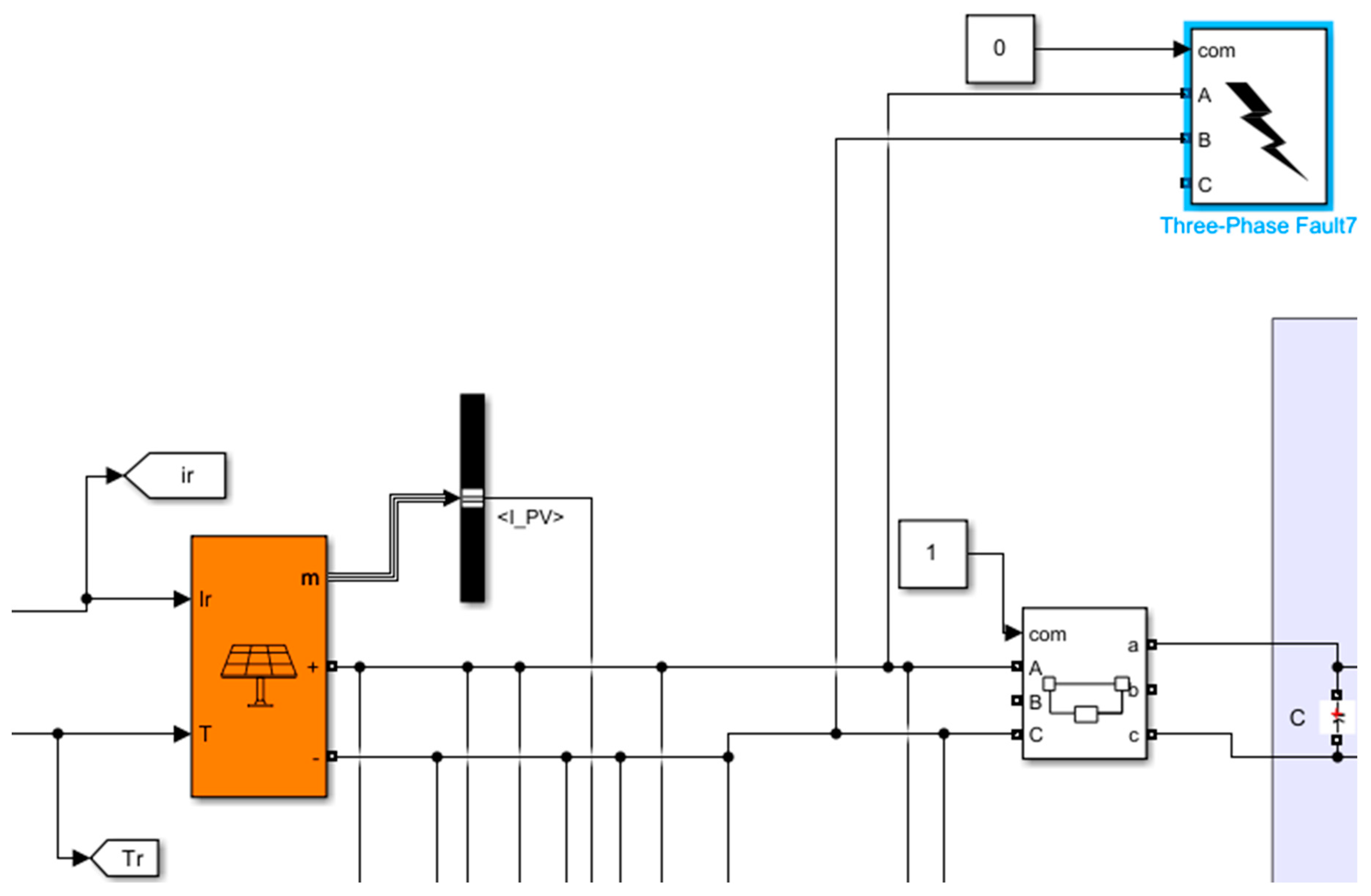
For a line–ground short-circuit fault to occur on the DC side, a fault condition is created by triggering the fault block selected in
Figure 11. The graphs in
Figure 4 and
Figure 5 were obtained. Looking at the graphs obtained from the measurements taken from the DC side, it is seen that a line–ground short-circuit fault causes large fluctuations in current and voltage. After the fault occurs, the DC voltage increases and decreases between 600 V and 1200 V. In order to prevent the simulation from stopping before the fault condition was observed, the circuit was not interrupted, and the fault condition continued for a while. In the graphs created with measurements taken from the AC side, it is seen that a line–ground short circuit occurring on the DC side does not directly affect the transformer output voltage but does affect the transformer output current.
3.6. DC Line–Line Short-Circuit Fault
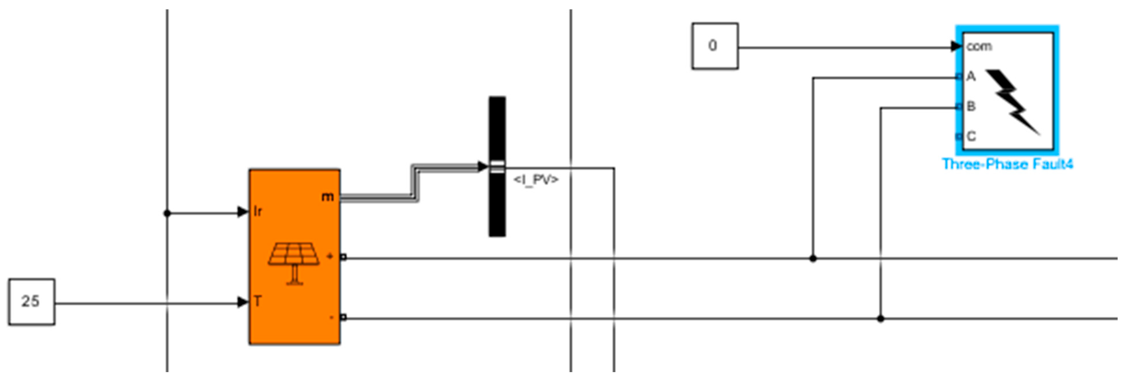
For a line-to-line short-circuit fault to occur on the DC side, a fault condition was created by triggering the fault block selected in
Figure 12. The graphs in
Figure 4 and
Figure 5 were obtained. Looking at the graphs obtained from the measurements taken from the DC side, it is seen that a line-to-line short-circuit fault causes the current and voltage to decrease to zero. In the graphs created with measurements taken from the AC side, it is seen that a line-to-line short circuit occurring on the DC side does not directly affect the transformer output voltage but does affect the transformer output current.
3.7. PV Module Fault
For photovoltaic module failure, a line-to-line short-circuit fault is created in the part symbolized as the combiner box on the DC side. To create this fault, a fault condition is created by triggering the fault block selected in
Figure 13. The graphs in
Figure 4 and
Figure 5 were obtained. By looking at the graphs obtained from measurements taken from the DC side, it is seen that a module fault causes large fluctuations in current and voltage. On the DC side, the voltage varies between 600 V and 1200 V, and the current varies between 1050 A and 1700 A. In order to prevent the simulation from stopping before the fault condition was observed, the circuit was not interrupted, and the fault condition continued for a while. In the graphs created with measurements taken from the AC side, it is seen that a short circuit occurring on the DC side does not directly affect the transformer output voltage, but it affects the transformer output current depending on how much of the module fault covers.
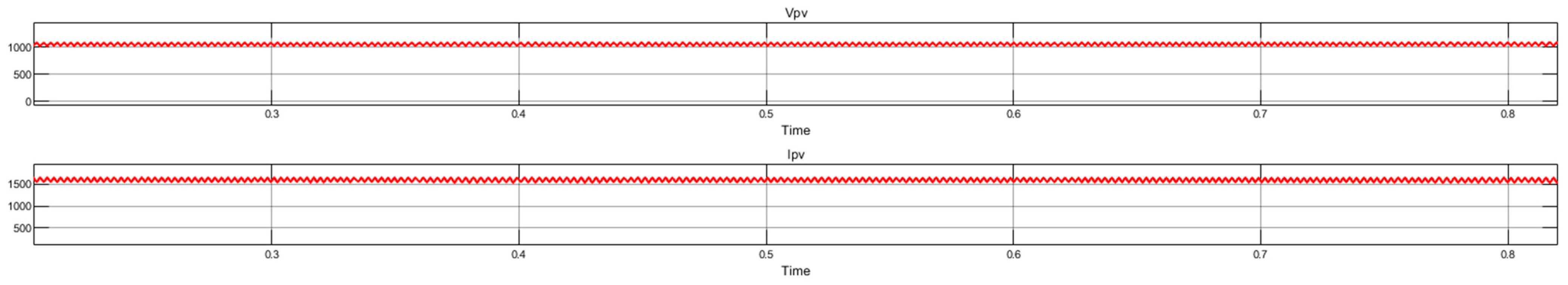
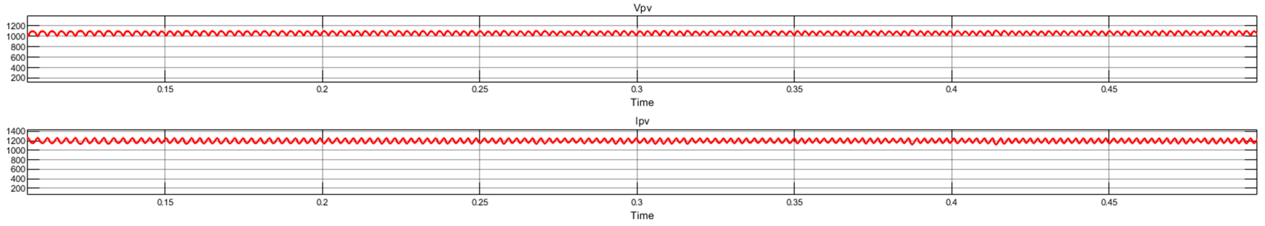
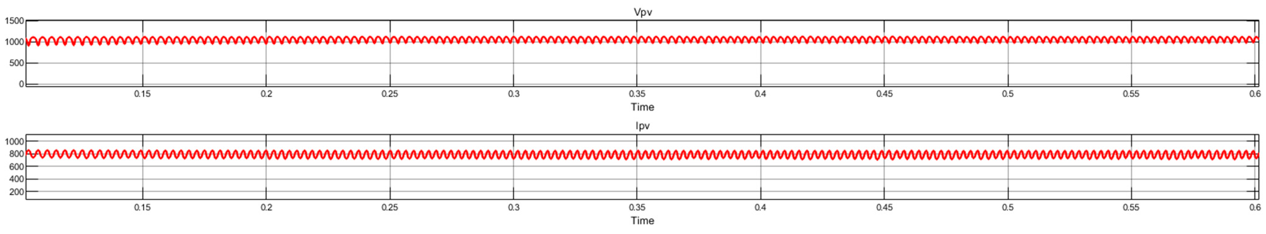
3.8. Mismatch Fault
Although the change in the amount of radiation is not a direct cause of failure, it was simulated to see its effect on power production. Changes in the amount of radiation directly affect the production amount and efficiency of a photovoltaic power plant. For this purpose, the effect on production was observed by changing the radiation amount to 1000 W/m
2, 750 W/m
2, and 500 W/m
2, respectively, in
Figure 14,
Figure 15 and
Figure 16 below.
In the figures above, when the amount of radiation increases, the current produced also increases. When the amount of radiation decreases, the current decreases as there will be irregular and insufficient production, and it becomes unstable enough to damage the system. In order to eliminate this uncertain situation, in control systems, minimum radiation amounts to activate inverters are defined.
4. Discussion
In this study, electrical faults in photovoltaic power plants are classified, these faults are modeled in the MATLAB Simulink program, and the measurement data are examined on graphics. Although the content of the studies examined from the literature research part of this study to the completion of this study is wide-ranging, some studies are directly related to the computer-based simulation of electrical faults in photovoltaic power plants. Not all studies have examined electrical faults in general terms similar to this study. While in some studies, only one fault is simulated [
28,
29,
30], in other studies, more than one fault is simulated [
31,
32,
33]. Furthermore, in other studies, no fault simulation output is produced, but the effects of the malfunction are mentioned [
5,
34].
In the Simulink model that was created, a phase-to-phase short-circuit fault on the AC side was modeled and the results were observed. In this case, it was observed that when a three-phase short-circuit fault occurs, the AC voltage goes towards zero, but the current value increases excessively, and the waveform is distorted. When the Simulink model created in this study was compared with other studies in the literature, similar results were obtained in the graphics, although the current and voltage values were different because the power plants used in the models had different power values [
28,
35,
36].
In the MATLAB Simulink model, it was observed that in open-circuit faults occurring at the inverter and grid output on the AC side, the current decreased to zero and the voltage amplitude and waveform were slightly distorted. When looking at previous studies, it can be seen that the results obtained are similar [
8,
37].
In the case of an open-circuit fault on the DC side, it was observed that the DC current decreased to zero, the DC voltage decreased but approached its nominal level in time, and on the AC side, the AC current approached zero and the AC voltage was not affected by the fault. In the previous studies, graphical outputs close to the graphics in this study were obtained [
32,
37,
38,
39].
In the photovoltaic power plant model, it was observed that a line-to-ground short-circuit fault on the DC side causes large fluctuations in DC current and voltage. On the AC side, it was observed that the mains voltage was not affected, but the current was affected by the fault condition. In contrast to these graphical outputs, in some studies in the literature, measurements were stopped when the short circuit started because the simulation was carried out as if the system protection elements were activated and the circuit was opened after the short circuit fault [
4,
38]. In some studies, similar graphs were produced by not interrupting the circuit and continuing the fault condition, as in this study [
37,
40].
In the graphs obtained by creating a line-to-line short-circuit fault on the DC side, it is seen that the line-to-line short-circuit fault on the DC side leads the current and voltage to zero. In the graphs created with measurements taken from the AC side, it is seen that a line-to-line short circuit occurring on the DC side does not directly affect the transformer output voltage but does affect the transformer output current [
37].
In the model, to create photovoltaic module failure, a line-to-line short-circuit fault is created. However, since the line-to-line short-circuit fault created for the module fault has a different place in the model, different results were obtained from the DC side line-to-line short-circuit fault. These results obtained in the MATLAB Simulink model are similar but different from previous studies. One of the reasons why the same graph cannot be obtained is that different graphic formats are used to show the outputs. In this study, current–time and voltage–time graphs were used, but some studies made explanations about the model through the current–voltage curve [
31,
41]. However, the results obtained were still similar to this study [
33,
42].
One of the reasons for electrical malfunctions in photovoltaic power plants is environmental factors. Since the part of a photovoltaic power plant that is more distributed on the site and can be more affected by environmental effects is the DC part, environmental effects are grouped as malfunctions that may occur on the DC side. In the MATLAB Simulink model, the effect of the change in the amount of radiation on production is shown, since showing environmental effects with short circuits and open circuits would be repeating previously simulated faults. The results obtained are parallel to the results obtained in previous studies [
29,
33,
43].
The application in this study differs from other studies in that it is fundamentally more comprehensive and has a wide variety of failures. The MATLAB Simulink model created in this study is created as detailed as possible so that all faults can be shown. During the literature review, it was seen that fewer faults were modeled in the studies examined. The studies were carried out for a specific fault group or a specific region of the photovoltaic power plant. This study is aimed to be a comprehensive study that includes all equipment and all fault zones of a photovoltaic power plant.
5. Conclusions
Faults in photovoltaic power plants are situations that prevent or reduce power production. While these malfunctions are sometimes easy to fix, sometimes it may take a long time to detect and fix them, and this may lead to financial losses.
In this study, electrical faults seen in photovoltaic power plants are classified and standardized. The classification process is made according to the places where the faults occur and the reasons why faults occur. With this categorization process, the possible causes and locations of malfunctions are described to make it easier to detect and eliminate malfunctions. A real power plant, which was implemented in the field, was modeled in the MATLAB Simulink program, electrical faults were simulated, and the results of the modeled faults were concretized. In this way, fault detection and finding solutions are no longer a challenge for businesses, and with the help of modeling fault situations, the equipment that may be affected by the fault and the ways in which it is affected are concretized.
In the study, the data that can be used to interpret the effects of faults are the graphical outputs of the model and the size of the region where the faults are created.
According to the graphical outputs obtained from the modeled faults, the fault type that has the most impact on the network is the phase-to-phase short-circuit fault that occurs on the AC side. It is seen that the phase-to-phase short-circuit fault occurring on the AC side is the fault that causes the biggest differences in current and voltage values. On the DC side, the highest value change was seen in the line–ground short-circuit fault that occurred on the DC side.
According to the graphical outputs obtained from the modeled faults, it is seen that the fault types that have the most impact on the system are line-to-line and line-to-ground short-circuit faults on the DC side. In photovoltaic power systems, there are various types of equipment on the DC side such as photovoltaic panels, combiner junction boxes, and DC input parts of inverters. For this reason, DC line-to-line and line-to-ground short-circuit faults are the faults that most affect the equipment in photovoltaic power plants.
Although causing production stops, it has been determined that the fault that has the least impact on the equipment and the least risk of permanent damage is the AC open-circuit fault.
Although there are other studies on this subject, the most important feature that distinguishes this study from other studies is that this study is comprehensive and detailed. Since the model here is a real photovoltaic power plant, similar work can be applied to other photovoltaic power plants.
Even though a real photovoltaic power plant is modeled in this study, the real effects of the faults may not be seen since most photovoltaic power plants do not record faults regularly. Also, it is not easy to detect all the faults in a power plant. In addition to this study, if the faults seen in a photovoltaic power plant are recorded in the future and modeled on MATLAB Simulink, then the model outputs can be compared with the fault records kept during the actual fault to test the accuracy of the model.


