Article

Experimental Study and Bearing Capacity Calculation of Compression-Reinforced Concrete Columns Strengthened with Ultra-High-Performance Concrete

School of Civil and Architectural Engineering, Guangxi University of Science and Technology, Liuzhou 545006, China
*
Author to whom correspondence should be addressed.
Appl. Sci. 2024, 14(5), 1911; https://doi.org/10.3390/app14051911
Submission received: 23 January 2024 / Revised: 16 February 2024 / Accepted: 16 February 2024 / Published: 26 February 2024

Abstract

:
A total of five ultra-high-performance concrete (UHPC)-strengthened reinforced concrete (RC) columns and one RC column were built and subjected to eccentric compression testing to examine the force performance of UHPC-strengthened eccentrically compressed plain RC columns. This experimental study examined the crack progression, the damage morphology, the deformation ability, the maximum load-carrying capacity, and the ductile properties of the eccentrically compressed columns. It also investigated the impacts of eccentricity, the reinforcement thickness, and the addition of steel fibers on the effectiveness of reinforcement. The cracking load, peak load, and ductility coefficient of the UHPC-reinforced specimens were increased by 100.28%, 172.30%, and 56.30%, respectively, compared with the RC column at an initial eccentricity of 50 mm. As the eccentricity distance increased, the bearing capacity of the UHPC eccentrically compressed specimens decreased, and the deformation capacity increased. Increasing the steel fiber dosage within the appropriate range decreased the crack width of the specimen. The addition of 2% steel fiber resulted in a 24.8% increase in cracking load, an 8.96% increase in peak load, and a 2.60% increase in ductility coefficient compared to the addition of 1% steel fiber. However, the reinforcing effect of UHPC was weakened under high eccentric pressures. Based on the theory of concrete structure and mechanical principles, the formula for calculating the compressive bearing capacity of RC columns strengthened with high-performance concrete was proposed. The results of calculating the positive section bearing capacity of eccentrically compressed RC columns reinforced with high-performance concrete are in good agreement with the test values. The results of this paper provide an experimental basis and theoretical foundation for the cross-sectional design of UHPC eccentrically compressed columns.

1. Introduction

The reinforcement of building structures has emerged as a significant sector within the construction industry, with several novel materials being extensively employed [1,2]. UHPC is a cementitious composite material containing fiber reinforcement known for its outstanding impermeability, robustness, resilience, and service life [3,4,5,6]. Additionally, UHPC is utilized in engineering to construct new bridges and repair and strengthen existing ones, domestically and globally [7,8,9,10]. UHPC was first derived from Mr. Hans Henrik Bache’s [11] first patent application and establishment of densified with small particles (DSP) theory. In 1994, Richard and Cheyrezy developed reactive powder concrete (RPC) with a compressive strength of 200–800 MPa, referring to DSP and the closest packing theory. In France in the same year, De Larrard and Sedran configured a mortar with a low water-to-cement ratio and a compressive strength of 236 MPa, and first proposed the concept of UHPC based on DSP theory [12]. In China, Professor Huang Zhengyu et al. at Hunan University conducted the earliest research on the development of UHPC technology, in 1993, using a 6% volume content of special steel fibers to prepare UHPC with a compressive strength of 200 MPa [13]. UHPC is not applied widely enough because of the high prices of raw materials and incomplete exploration of structural theories. However, its large-scale application will become feasible as the UHPC preparation technology gradually matures and the standards and depth of structural research improve. UHPC is being increasingly applied to the main structures of actual projects. The global application of UHPC materials in bridges increased to more than 1000, mainly in Asia, North America, and Europe [14]. UHPC is mostly used for localized reinforcement or the repair of critical parts of bridge abutments. Caluk utilized UHPC to enhance the plastic hinge zone of a bridge abutment, and the test results proved that UHPC can significantly reduce the damage to a plastic hinge zone, with good deformation and energy dissipation capacity [15]. The utilization of cementitious elements in the design of UHPC promotes sustainable development by achieving slender cross-sections, resulting in reduced concrete usage (specifically, less cement). This reduction in cement leads to decreased energy consumption and lower CO2 emissions [16]. According to Maria Amata Garito and other experts, the European Green Deal aims to reach complete carbon neutrality by 2050, thereby mitigating the environmental impact of industrial activities [17]. The extensive utilization of UHPC will additionally foster the advancement of sustainable buildings. This has significant ramifications for the preservation of the environment and the promotion of sustainable development. Currently, several building structures in China have been in use for an extended period, exhibiting varying levels of degradation, inadequate load-bearing capacity, and other issues.
Several research studies have been conducted both domestically and globally on specimens that have been strengthened with UHPC. These investigations primarily focused on two areas: experimental research on axially compressed columns reinforced with UHPC, and experimental research on the performance of eccentrically compressed columns using other composite materials. In 2014, Liangtao Bu [18] and colleagues conducted an experimental investigation on the axial compressive parameters of RC columns reinforced with UHPC. The study demonstrated considerable improvements in the ultimate bearing capacity, peak strain, cracking load, and ductility of the reinforced specimens. In 2023, Chunling Lu [19] and colleagues conducted an experimental study on the axial compressive properties of UHPC-RC columns. The study demonstrated that UHPC reinforcement significantly enhanced the axial bearing capacity and ductility of the specimens and that the increase in the bearing capacity was directly proportional to the thickness of the UHPC. RC columns seldom experience pure axial compression pressures in real-world engineering scenarios. Therefore, it is crucial to enhance the material’s ductility to improve the stress performance of the eccentric compressed elements. In 2019, LingZhi Li [20] and colleagues performed eccentric compression tests on an engineered cementitious composite (ECC). The tests were performed with a considerable eccentricity of 120 mm. The results indicated that the ECC could substitute certain steel bars. In 2023, Xinling Wang [21] and colleagues performed eccentric compression tests on low-eccentric-compression RC columns reinforced with an ECC. The test results showed the superiority of the small ECC-reinforced low-eccentric-compression RC columns compared with plain- mortar-reinforced RC columns. As a result, a variety of cementitious materials for reinforcement are used in a wide range of reinforcement applications, such as micromechanical reinforcement systems for ECC, where fibers play a key role in the establishment of ultra-high tensile ductility and the control of self-generated crack widths [22]. In addition to utilizing carbon nanotubes (CNTs) as reinforcing agents for ECC, nanomaterials have demonstrated the ability to impact porosity, enhance pore structure, expedite cement hydration, and augment the tensile and flexural strength of ECC in order to effectively suppress cracking and expansion. However, certain challenges still remain [23]. This will also serve as a trajectory for the advancement of cementitious materials like ECC and UHPC. Simultaneously, this particular cement-based substance will further advance in the realm of reinforcing.
To summarize, applying UHPC-RC greatly enhances bearing capacity and ductility. However, the current research has mostly concentrated on the performance of axial compression. UHPC-reinforced eccentrically compressed columns are important for enhancing the brittle damage characteristics of minor eccentrically compressed aspects and increasing the ultimate bearing capacity of major eccentrically compressed elements of the component. Hence, this study suggests employing UHPC-strengthened RC columns for conducting eccentric compression testing. The experiments examined the impacts of the eccentricity, UHPC reinforcement thickness, and UHPC steel fiber dose on the damage pattern, deformation capacity, and bearing capacity of eccentrically compressed specimens. This study presents the formula for determining the compressive load capacity of UHPC eccentrically compressed specimens in the normal section. This formula serves as an experimental and theoretical basis for designing the cross-sections of UHPC eccentrically compressed specimens. Moreover, the results of the experimental study provide informative value for the application of eccentric specimen reinforcement or UHPC-RC composite structures in existing buildings. Additionally, they enable the provision of design value for the reinforcement application of UHPC and play a crucial role in advancing green buildings in terms of sustainability.

2. Experimental Design

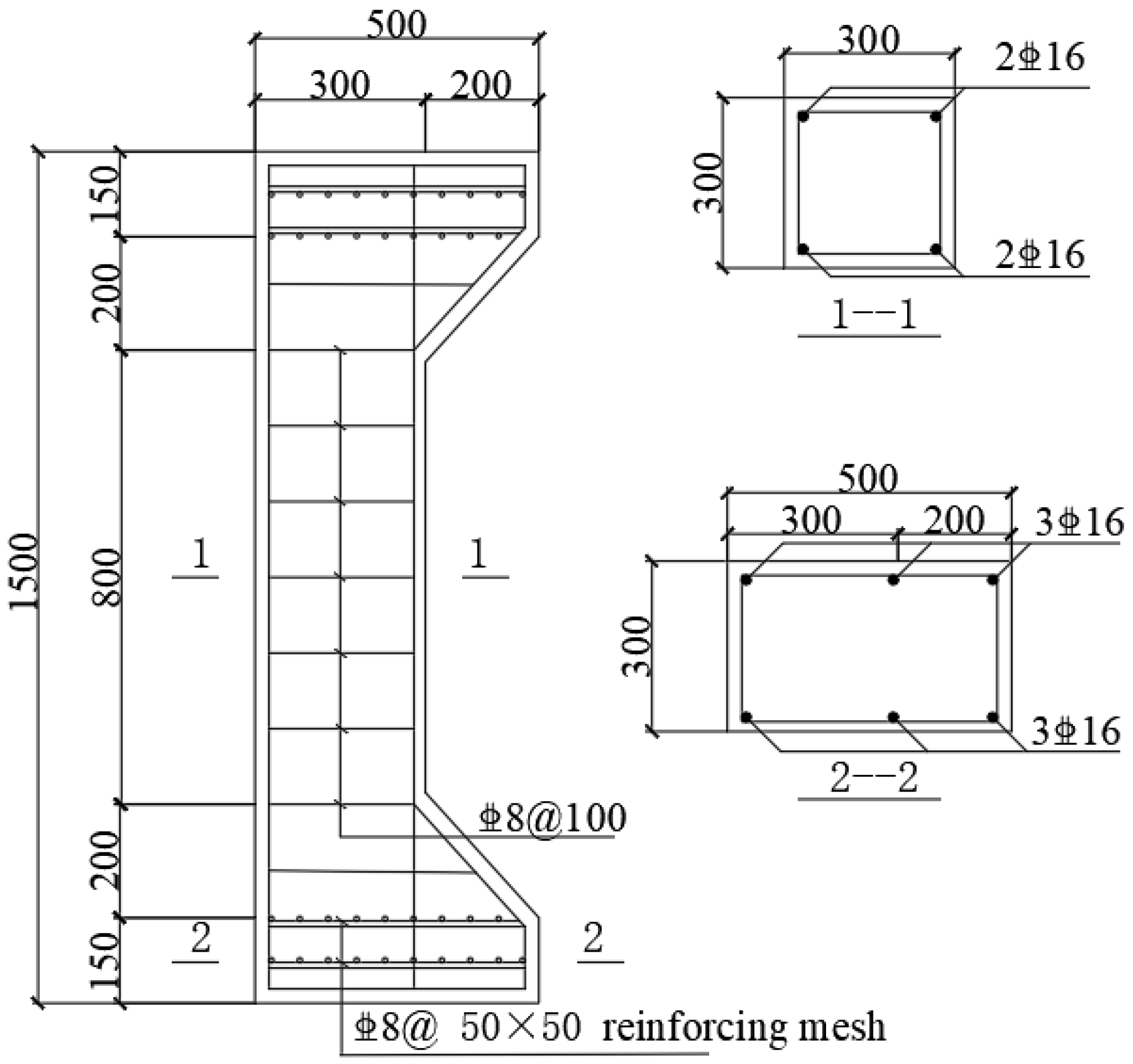
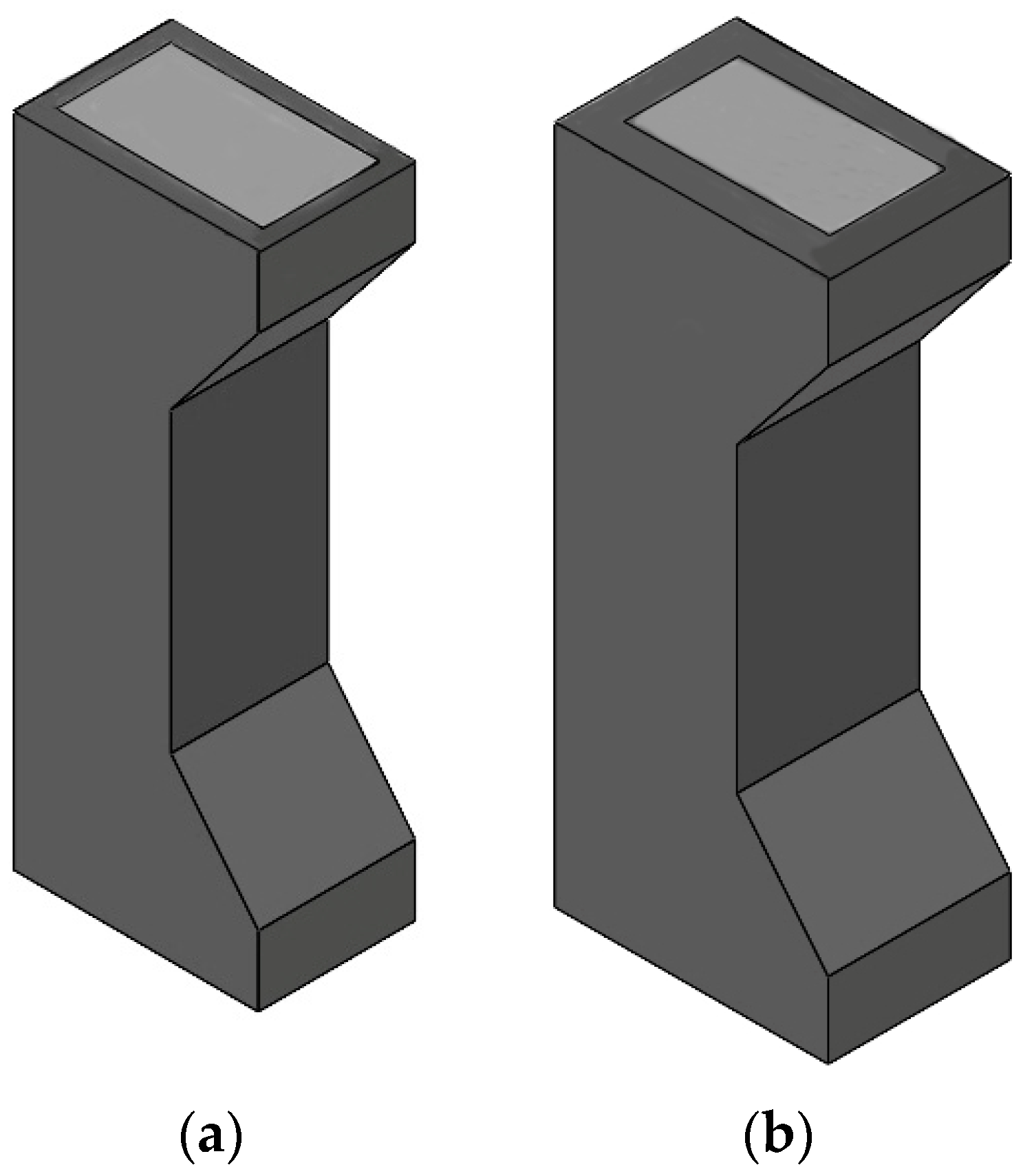
2.1. Specimen Design

The experiment involved the creation of five columns reinforced with UHPC and one comparator column subjected to eccentric compression. The design specifications for the test columns may be found in Table 1. The test conditions consisted of three different eccentricity values (50 mm, 100 mm, and 150 mm), two UHPC reinforcement thicknesses (30 mm and 50 mm), and two steel fiber volumetric dosages (1% and 2%). Figure 1 displays the dimensions of the specimen’s cross-section and diagrams illustrating the reinforcement. The RC specimens were made of concrete with a strength grade of C40. The protective layer of concrete had a thickness of 25 mm. All test specimens had a cross-section size of 300 mm × 300 mm, and a total height of 1500 mm. HRB400 reinforcing steel was utilized symmetrically to prevent excessive local pressure and splitting damage in the bull leg column. Two rows of 50 × 50 mm reinforcing steel mesh were installed at each end of the bull leg column section.

2.2. Reinforcement Program

The design of the reinforcement program referred to China’s GB50367-2013 “Design Code for the Reinforcement of Concrete Structures” [24], and the UHPC-reinforced RC columns were constructed using a four-sided enclosure of external reinforcement. A three-dimensional schematic of the reinforced specimens is shown in Figure 2. The surfaces of the RC columns maintained for 28 days were chiseled and chamfered before surface cleaning. The interfacial agent was brushed before pouring. The pre-mixed UHPC was then poured into the specimen for reinforcement, after which moist maintenance was carried out.

2.3. Mechanical Properties of Concrete and Steel Reinforcement

One day before the test, the reserved C40 and UHPC specimens were tested per China’s “Standard GB/T50081-2002 for Test Methods of Mechanical Properties of Ordinary Concrete” [25] and “Basic Properties of Ultra-High Performance Concrete in Test Methods” (T/CBMF37-2018; T/CCPA7-2018). The length of the steel fibers used in UHPC is 12 to 14 mm. The mechanical properties of C40 and UHPC are shown in Table 2. The reinforcing bars underwent tensile tests per the methods specified in Part 1 of the “Tensile Test of Metallic Materials in China’s Room Temperature Tensile Test Methods for Metallic Materials” (GB/T 228.1-2021) [26]. The material properties of the reinforcing bars are shown in Table 3.

2.4. Test Setup and Content

The test specimen was loaded onto a 10,000 kN hydraulic servo tester with knife-edge supports at each end of the column along the direction of eccentric pressure. The arrangement of loading device and concrete strain gauges is shown in Figure 3. Three strain gauges with the same spacing were arranged vertically and one strain gauge was arranged horizontally on the four faces of the specimen surface at the mid-axis of the specimen surface in sequence. Five displacement gauges were arranged at the mid-span position of the tensile side surface of the specimen, at the top and bottom of the column, and at the root of the bull leg to measure the lateral deflection of the specimen. Loading was carried out according to China’s “Standard for Test Methods of Concrete Structures” [27]. Preloading was carried out before formal loading to ensure the test device was in normal working conditions. The distribution of the strain gauges in the reinforcement is shown in Figure 3. Two steel strain gauges were pasted in the middle of each of the four longitudinal bars to measure the strain of the longitudinal bars. At the same time, one strain gauge was pasted around each of the three hoops in the middle of the specimen to measure the strain of the hoops.

3. Results and Discussion

3.1. Specimen Crack Development and Damage Pattern

3.1.1. Damage Patterns of Eccentric Compression Specimens

Unreinforced contrasting specimen Z1: At the beginning of loading, the appearance of specimen Z1 was unchanged. When loaded to approximately 1030 kN, two small parallel horizontal cracks appeared in the middle of the lateral tensile zone of the specimen. When loaded to the peak load of 2401.40 kN, longitudinal cracks appeared in the compression zone, the concrete was crushed and spalled in large chunks, the bearing capacity sharply decreased, the damage zone elongated, and the specimen was destroyed. The specimen lacked obvious signs before damage and showed typical low-eccentricity-compression brittle damage. The damage pattern is shown in Figure 4.
UHPC-reinforced specimen Z2-1: At the beginning of loading, the appearance of specimen Z1 was unchanged. When loaded to 31% of the peak load, small horizontal cracks appeared at the edges of the tensile side of the specimen and tiny vertical cracks appeared at the end of the specimen. The cracks on the tensile side developed more slowly as the load increased. When loaded to 2078 kN, several irregular horizontal cracks appeared in the compression zone of the specimen, vertical cracks appeared at the edges of the compression zone, and the sound of steel fiber being pulled off could be heard. The load then dropped, and the end of the UHPC compression zone was crushed when the load dropped to 85% of the peak load. However, reinforced specimen Z2-1 exhibited better integrity and some ductile damage characteristics compared with the unreinforced specimen. When examined closely, UHPC is employed to strengthen and prevent cracks from spreading by enhancing the pore structure of the composite material. The damage pattern of reinforced specimen Z2-1 is shown in Figure 5.

3.1.2. Damage Patterns of High-Eccentric-Compression Specimens

The distribution of damage cracks and damage diagram of a typical UHPC-reinforced RC column with high-eccentric-compression specimens are shown in Figure 6.
UHPC-reinforced specimen Z2-2: At the beginning of loading, the appearance of specimen Z1 was unchanged. When loaded to 1532 kN, the first small horizontal crack appeared in the middle of the tensile zone of the specimen. As the load increased, the crack gradually expanded to the compression zone, forming a major horizontal crack in the compression zone. When the load was increased to 3123 kN, diagonal cracks appeared in the bull leg columns in the lower part of the compression zone, and vertical fine cracks developed to approximately 0.3 mm. When loaded to the peak load of 4596.30 kN, the main crack on the tensile side appeared in the upper bull leg column with a width of approximately 1 cm; meanwhile, three transverse cracks with smaller widths parallel to the main crack appeared. The specimen exhibited a damage pattern of high eccentric compression.
UHPC-reinforced specimen Z2-3: At the beginning of loading, the appearance of specimen Z1 was unchanged. When loaded to 1314 kN, the first small horizontal crack appeared at the edge of the tensile zone of the specimen, and the number of horizontal cracks slowly increased, showing the characteristics of many dense horizontal cracks. When loaded to 1980 kN, significant longitudinal cracks appeared at the end of the reinforcement on the compression side. When loaded to the peak load of 2703.90 kN, transverse main cracks in the specimen tensile zone suddenly appeared, alongside the steel fiber fracture phenomenon. Traces of steel fibers were pulled out. The bias column specimen damage process was very gentle. The compression zone appeared in vertical specimen damage cracks, but the specimen tensile zone cracks were more uniformly distributed. The specimen exhibited a damage pattern of high eccentric compression.
UHPC-reinforced specimen Z3: At the beginning of loading, the appearance of specimen Z3 was unchanged. When loaded to 1020 kN, the first transverse crack with a width of approximately 0.05 mm appeared in the middle of the tension zone. As the load increased, the transverse cracks gradually increased and became slowly widened. At the same time, a network of fine cracks appeared in the lower part of the compression zone of the bull leg column. When loaded to the peak load of 2481.50 kN, longitudinal cracks appeared in the compression zone, the main crack penetrated, and the specimen was damaged. The specimen exhibited a damage pattern of high eccentric compression.
UHPC-reinforced specimen Z4: At the beginning of loading, the appearance of specimen Z4 was unchanged. When loaded to approximately 1538 kN, a small transverse crack appeared in the middle of the tension zone, and a vertical crack also appeared at the top of the compression zone. As the load increased, the number of transverse cracks increased, and vertical cracks appeared at the top of the compression zone. When loaded to the peak load of 3923.70 kN, the main crack penetrated the tensile zone, longitudinal cracks appeared in the compression zone, and the specimen was damaged. There was no spalling of the protective layer, and the integrity was good after destruction. The specimen exhibited a damage pattern of high eccentric compression.

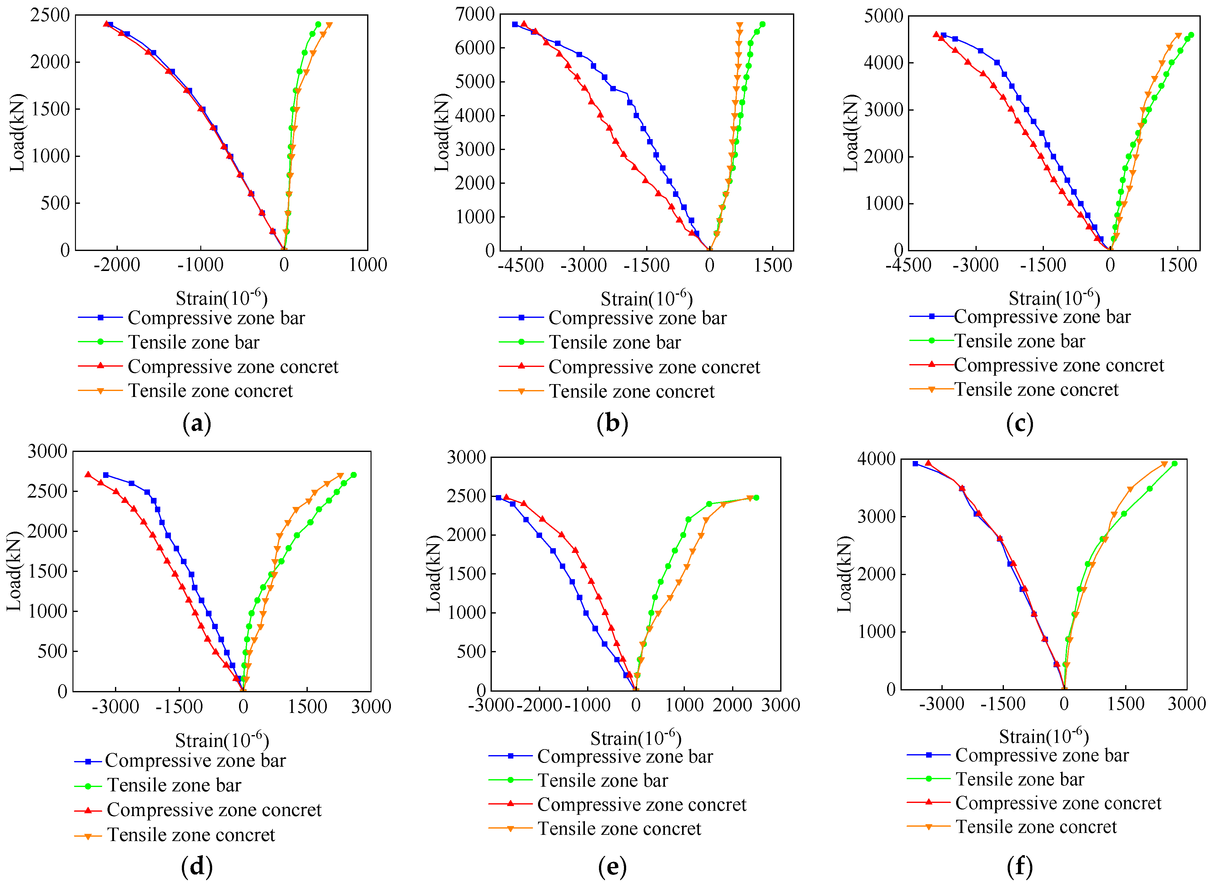
3.2. Strain Distribution

The strain distribution curves of the concrete UHPC and reinforcement for each specimen under different loading levels are shown in Figure 7.
As shown in Figure 7a, for comparison specimen Z1, the concrete at the edge of the compression zone was crushed when the load reached the peak load. Its ultimate compressive strain was 2127.462 μ ε . The compressive strain of the reinforcement in the compression zone was 2083.488 μ ε , and the reinforcement on the compression side reached yield, and the strain in the reinforcement in the tensile zone was 408.126 μ ε , and the reinforcement in the tensile zone did not reach yield. These results show that the strain development pattern of the Z1 cross-section of the comparison specimen is consistent with the characteristics of low-eccentric-compression damage.
As shown in Figure 7c, for reinforced specimen Z2-2, when the load reached 84% of the peak load, the strain in the tensile reinforcement was 2011.51 μ ε , the tensile reinforcement yielded, and the strain in the concrete in the compression zone was 2566.47 μ ε . When the load reached the peak load, the concrete strain at the edge of the compression zone was 3640.15 μ ε , reaching the ultimate compressive strain. These results show that the reinforcement in the tension zone yielded before the concrete at the edge of the compression zone of the specimen reached the ultimate compressive strain. The strain development pattern in the cross-section of reinforced specimen Z2-2 was consistent with the characteristics of high-eccentric-compression damage.

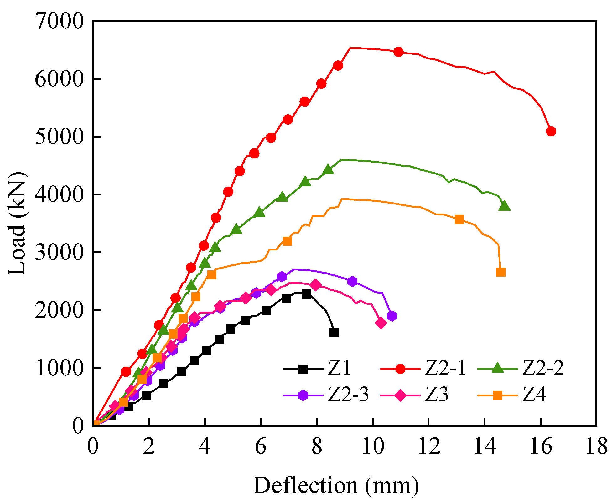
3.3. Load–Lateral Displacement Curves

The lateral displacement of the specimen at the center of the column under the ultimate load in the test was taken as the ultimate deflection value. The load column mid-span deflection curves for each specimen are shown in Figure 8. Compared with the unreinforced specimens, the stiffness of the reinforced structure was significantly higher than that before reinforcement, and the deformation capacity was greatly improved. The curve trends are broadly divided into four stages. The elastic phase: when loaded to approximately 25% of the peak load, the slope of the curve was steeper, and the deflection grew at a slower rate because the crack resistance of UHPC is better than that of ordinary concrete. No cracks appeared on the surface of the specimen, and the curve of the specimen in this phase was approximately linear. The elastic–plastic phase: with the slow load increase, rapid deflection growth, and curve fluctuation, the specimen entered the elastic–plastic working state. The longitudinal reinforcement of the reinforced specimen did not yield. The deformation of the specimen increased faster, while the growth in the load slowed. The curve showed non-linear changes in this phase. The plastic phase: the load slowly grew, the deflection rapidly increased, the curve fluctuated, the specimen entered the elastic–plastic working state, the longitudinal stress reinforcement of the reinforced column did not yield, the deformation of the specimen grew faster, and the load grew slower. The descending phase: as the curve entered the descending phase, the vertical cracks in the UHPC in the compression zone became significantly wider, and their restraining effect on the core concrete in the compression zone decreased. When the load was reduced to approximately 75% of the peak load, the UHPC at the bottom of the compression zone was crushed, and the specimen was damaged but still retained good integrity. The descending section of the specimen curve after UHPC reinforcement was slower than that of the comparison column, which indicates that the late ductility of the UHPC-reinforced eccentric compression columns was improved, and the final deflection in the span was reduced to different degrees, which indicates that the UHPC reinforcement can improve the specimen’s ability to resist deformation.

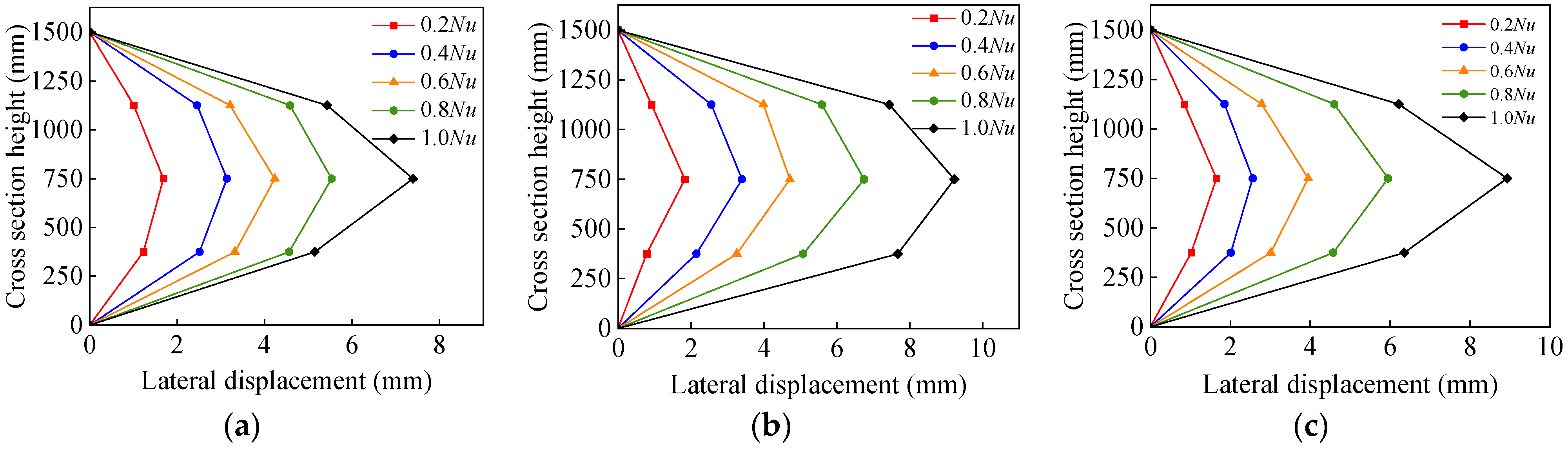
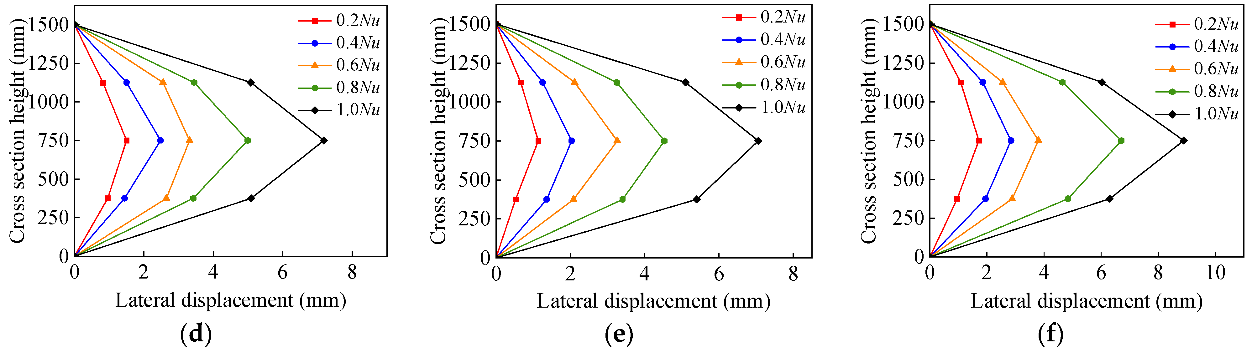
3.4. Lateral Deformation of Specimens

The lateral deflection curves of each specimen under different load levels are shown in Figure 9. At the beginning of loading, the growth rate of the lateral deflection of each specimen was slow and accelerated when the load was increased to 0.8 N u . The mid-span deflection of the specimen was always at maximum during loading. The lateral deflections of the specimens were symmetrically distributed, with the high center of the column as the boundary. The column height lateral deflection curves of the compression columns were all similar to the sinusoidal function curves. The lateral deformation curve of the eccentric compression specimen conformed to a sinusoidal half-wave curve.
Observing contrasting specimen Z1 and reinforced specimen Z2-1 in Figure 9, the lateral deflection of the specimen grew at a slower rate at the beginning of loading. When the load was increased to 0.8 N u , the lateral deflection deformation of the specimen steeply increased, and the mid-span deflection of reinforced specimen Z2-1 was larger than that of contrasting specimen Z1. This indicates that, after the core concrete was crushed, the peripheral reinforcement layer UHPC was gradually compacted, and the specimen gained load-bearing capacity again, increasing the ductility and ultimate load bearing capacity of the reinforced specimen.

3.5. Mechanical Properties Analysis

The main test results of each specimen are shown in Table 4.

3.5.1. Load-Bearing Capacity Analysis

(1)
Comparison of test pieces Z1 and Z2-1 (50 mm eccentricity)
The ultimate bearing capacity of reinforced specimen Z2-1 was increased by 172.30% compared with comparison specimen Z1. This was due to the excellent tensile properties of UHPC and the lassoing effect of the UHPC reinforcement on the core concrete. The UHPC reinforcement layer provided more effective restraint to the core concrete, which significantly increased the ultimate load capacity of the specimen.
(2)
Reinforced specimens Z2-1, Z2-2, and Z2-3 (reinforcement thickness of 30 mm)
When the reinforcement thickness was 30 mm and the steel fiber dosage was 2%, the eccentricity values of Z2-1, Z2-2, and Z2-3 were 50 mm, 100 mm, and 150 mm, respectively. The ultimate bearing capacity of reinforced specimen Z2-1 was increased by 42.7% and 141.80% compared with Z2-2 and Z2-3. The effect of eccentricity on eccentrically compressed columns after UHPC reinforcement was similar to that on the normal eccentrically compressed columns, whereby the ultimate bearing capacity decreased with increasing eccentricity.
(3)
Reinforced specimens Z2-3 and Z3 (reinforcement thickness 30 mm)
The ultimate load-carrying capacity of specimen Z2-3 with 2% steel fiber doping increased by 8.96% compared with specimen Z3 with 1% steel fiber doping when the reinforcement thickness was 30 mm and the eccentricity was 150 mm. This was mainly because the UHPC steel fiber volume admixture was in the appropriate range, and steel fiber can inhibit cracks more effectively and possess better tensile capacity, which improves the ultimate bearing capacity of the specimen. The strength and ductility of UHPC after cracking were mainly provided by fiber-reinforced toughening. For example, Su-Tae Kang studied the tensile fracture properties of UHPC considering the effect of the steel fiber content. In this case, the steel fiber volume ratio was changed from 0% to 5%.The flexural tensile strength of UHPC increased linearly with the increase in the steel fiber volume ratio [28].
(4)
Reinforced specimens Z2-3 and Z4 (2% steel fiber)
The ultimate load capacity of specimen Z4 reinforced with a 50 mm thickness was increased by 45.11% compared with specimen Z2-3 reinforced with a 30 mm thickness when the thickness of the reinforcement was 30 mm and the eccentricity was 150 mm. This shows that the thickness of the UHPC reinforcement increases the specimen’s ultimate load capacity. Enhancing the thickness of the reinforcement can significantly enhance the force distribution in the reinforcement member column, thereby reducing the original column’s eccentricity by enlarging the member’s cross-section. This transformation converts the member from a partially loaded section to a fully loaded section. The eccentricity of the original column causes a portion of the cross-section to experience compression, resulting in full cross-section compression. The member undergoes a transformation from a partially compressed segment to a fully compressed section, resulting in enhanced utilization of the concrete material. This leads to a substantial increase in stiffness, and the rigidity and maximum load-bearing capability of the component are significantly enhanced.

3.5.2. Ductility Analysis

Ductility is an important parameter in structural design to characterize deformation capacity. The ductility coefficient of reinforced specimen Z2-1 increased by 56.24% compared with unreinforced specimen Z1 under low eccentric compression. The UHPC reinforcement layer effectively restrains the core concrete in the compression zone, resulting in increased strength and deformation capacity. This significantly enhances the ductile properties of the RC eccentric column when the core concrete undergoes large lateral expansion and deformation. The ductility coefficients of reinforced specimen Z2-1 increased by 7.01% and 22.46% compared with reinforced specimens Z2-2 and Z2-3. The ductility of the material deteriorated as the eccentricity increased. Nevertheless, the fragility of the RC eccentric compression columns was much improved with the incorporation of UHPC reinforcement. This enhancement resulted in substantial anticipated damage and significantly enhanced the malleability of the specimens. The specimens exhibited a substantial improvement in ductility. The ductility coefficient of reinforced specimen Z2-3 increased by 2.60% compared with specimen Z3 under high eccentric compression. This shows that the steel fiber dosage affects the ductile properties. The ductile properties of reinforced specimen Z2-3 were increased by 9.08% compared with specimen Z4. The thickness of the UHPC reinforcement layer enhanced the ductile properties.

3.6. Calculation of Compressive Bearing Capacity in Positive Section

The calculation of the eccentric compressive load capacity of the HHPC-reinforced column consisted of two parts: the load capacity provided by the original RC column restrained by the UHPC, and the load capacity provided by the UHPC in the reinforced layer. Cross-section limit equilibrium theory is used to establish the calculation method for the eccentric compressive load capacity of this reinforced column.

3.6.1. Basic Assumptions

The HUPC reinforcement method for strengthening eccentric compression columns followed the enlarged section method in GB50367-2013 “Design Code for Reinforcement of Concrete Structures”. Based on the enlarged section method and the results of the experimental study, the following basic assumptions were adopted:
  • The strains in the UHPC reinforcement, plain concrete, and stressed longitudinal bars satisfied the flat section assumption;
  • Without considering the tensile action of the concrete in the original structure, the stress–strain relationship model between the concrete under compression and the longitudinal reinforcement from the concrete structure design code was adopted;
  • The relative slip of the UHPC to the original structural concrete was not considered;
  • Due to the high tensile strength of UHPC, the role of the tensile properties of UHPC in the tensile zone was considered in the calculation of the bearing capacity of the UHPC columns, and the bearing capacity of the UHPC at the sides was considered.

3.6.2. Calculation of Bearing Capacity of UHPC-Reinforced Eccentrically Compressed Columns

Based on the results of the experimental study and theoretical analyses, the calculation model of the eccentric compressive load capacity of rectangular cross-sectional UHPC-reinforced columns was plotted as shown in Figure 10.

3.6.3. Calculation Formulae for Bearing Capacity of UHPC High-Eccentric-Compression Specimens

For high-eccentric-compression damage, the stress in the longitudinal tensile reinforcement A S was taken as the tensile strength f y , and the stress in the longitudinal compressive reinforcement A S was taken as the compressive strength f y . The equilibrium condition for the longitudinal forces and the moment equilibrium condition for the moment taken by each force on the combined point of tension reinforcement led to the following two basic equations:
N = α 1 f c c b x + 2 α 1 f c t x + f y A s f y A s σ u b t
N e = α 1 f c c b x ( h 1 x 2 ) + 2 α 1 f c t x ( h 0 x 2 ) + f y A s ( h 0 a s ) σ u b t ( t 2 a s )
e = e 0 + 0.5 h a s
e i = e 0 + e a
Here, f c c was approximated according to the code for f c c = 1 2 ( f c 0 + 0.9 f c ) in the “Design of Reinforcement of Concrete Structures”, where f c c —the axial compressive strength of the combined section of the old and new concrete; f c 0 , f c —the axial compressive strength of the old and new concrete, respectively; α 1 —the ratio of the stress value of the rectangular stress diagram of the concrete in the compression zone to the axial compressive strength of the concrete, which was determined via linear interpolation, where 0.88 was the value derived [29]; x —the height of equivalent pressure zone; t —the UHPC reinforcement thickness; e —the distance from the point of application of the axial force to the confluence point of the longitudinal tensile reinforcement; e i —the initial eccentricity; e 0 —the eccentricity of the axial pressure against the section’s center of gravity; e a —the additional eccentricity, determined by the maximum size of the section in the direction of the eccentricity, h , where h > 600 , and e a = h / 30 ; the stress value of UHPC equivalent rectangular stress diagram in tensile zone, σ u = k f c , where k is 0.40 [29]. The effective height of the original cross-sectional specimen was the distance from the combined point of the longitudinal reinforcement on the tension side or the less compressed side to the more compressed edge of the reinforced cross-section.

3.6.4. Calculation Formulae for Bearing Capacity of UHPC low-Eccentric-Compression Specimens

With low-eccentric-compression damage, the stress of the reinforcement in the compression zone can reach the yield strength, so the stress of the longitudinal compression reinforcement A s , is taken as the compressive strength f y . The reinforcement on the far side of the tensile zone may be tensile or compressive, but none of them can reach the yield strength, so the stress in A s is expressed as σ s . For symmetrically reinforced ultra-high-performance concrete reinforced RC columns subjected to low eccentricity damage, its tensile zones are small. Therefore, the effect of tensile stresses in the ultra-high performance concrete is not considered in the load capacity calculation. From the equilibrium conditions for the longitudinal forces in the section and the moment equilibrium conditions for the moment taken by each force on the combined point of the tensile reinforcement, the following two basic equations can be obtained:
N = α 1 f c c b x + 2 α 1 f c t x + f y A s σ s A s
N e = α 1 f c c b x ( h 1 x 2 ) + 2 α 1 f c t x ( h 1 x 2 ) + f y A s ( h 0 a s )
σ s = ( 0.8 h 1 x - 1 ) E s ε c u
where ε c u —the limit compressive strain of high-performance concrete, taken as 0.005 [30,31]; E s —the modulus of elasticity of reinforcement.

4. Analysis of Calculation Results

The bearing capacity of the specimen calculated according to the theoretical formulae as well as the actual test results are shown in Table 5. The ratio of the theoretical to experimental values had a mean value of 1.031, a standard deviation of 0.32, and a coefficient of variation of 0.31. This indicates that, for UHPC-reinforced biased RC columns, the ultimate bearing capacity obtained using the theoretical calculation method is in good agreement with the test values, with low data dispersion, and can accurately predict the bias bearing capacity of the reinforced specimens. This shows that the design calculations for this type of reinforcement method according to the roll-out formula are on the conservative and safe side. However, the test values under eccentric pressure in this paper still deviate from the theoretically calculated values. Based on the observation of the phenomenon during the test, this gap may be caused by the relatively large difference in roughness between UHPC and the substrate material, and a small portion of the bonding surface detaches under eccentric pressure in some specimens. The cracks appeared on the bonding surface first. For this problem, the introduction of coarse aggregate into the UHPC system has gradually attracted the attention of scholars at home and abroad [32]. Adding a coarse aggregate can improve the traditional UHPC and reduce the amount of cementitious materials, as well as help improve the volume stability, reduce production costs, and increase the roughness of the UHPC [33], which allows the UHPC to fit the bonding surface better when used as a reinforcing material. However, the introduction of coarse aggregates has brought new challenges to the regulation of UHPC construction performance. Good homogeneity and densification are the basis for ensuring performance indexes, whereas unevenness is caused by layered settlement or uplift due to differences in the density of the concrete components. Scholars at home and abroad have researched concrete stability, exploring the effects of coarse and fine aggregates, mineral admixtures, external disturbances, and other factors. The conductivity method, visible slurry method, colored aggregate method, hydrostatic pressure test method, ultrasonic speed method, and other test methods and evaluation standards have been developed. These problems will be solved with the gradual maturation of UHPC preparation technology.

5. Conclusions

In this study, eccentric compression tests of five UHPC-reinforced RC columns and one comparison RC column were designed and carried out. Based on the results of the eccentric compression tests and theoretical analyses, the following main conclusions were drawn:
  • UHPC reinforcement improved the load carrying capacity and ductility of eccentrically compressed columns; however, their ultimate load carrying capacity gradually decreased as the eccentricity increased.
  • The stress performance of the UHPC-reinforced eccentric compression columns was greatly improved. The ultimate load capacity and ductility coefficient of the UHPC-reinforced specimens increased by 172.30% and 56.24%, respectively, compared with the comparison RC columns under low eccentric compression.
  • The thickness of the UHPC reinforcement layer had a greater effect on the reinforcement effect. When the eccentricity was 50 mm, the ultimate bearing capacity and ductility coefficient of the reinforcement layer thickness of 50 mm were increased by 45.11% and 9.08%, respectively, compared with an eccentricity of 30 mm.
  • When the volume of the UHPC steel fiber dosage was within a suitable range, the steel fiber dosage impacted the reinforcement effect. The ultimate load-carrying capacity and ductility coefficient of the columns with 2% UHPC steel fiber by volume were increased by 8.96% and 2.60%, respectively, compared with the columns with 1% UHPC steel fiber by volume.
  • Based on the limit equilibrium theory and considering the tensile contribution of UHPC, the formula for calculating the ultimate bearing capacity of eccentrically compressed RC columns reinforced with UHPC was provided, and the error of the calculation results is small, which can be used as a reference in the design of reinforcements.
  • Using UHPC both for reinforcement and new construction has many shortcomings. For example, the cost of UHPC raw materials is approximately 10–15 times that of ordinary concrete, resulting in a high cost of material use. The imperfections in the theory of UHPC structural design make it difficult to apply on a large scale in the main structure of a building or a bridge. The roughness of the UHPC interface affects the interfacial adhesion of the base material in the repair and reinforcement, resulting in the detachment of some parts of the interface over a long period when the load is being held. Nevertheless, UHPC still represents a sustainable development of new reinforcement materials. The application of UHPC in the repair and reinforcement of new bridges at home and abroad and existing bridges is an exponentially growing trend. With the deepening of the study of materials and structures, it can be predicted that the development of relevant norms and standards will propel the applications of UHPC.

Author Contributions

Conceptualization, X.L., C.J. and W.L.; experiment, M.P., W.C. and H.Z.; resources, X.L., C.J. and W.L.; writing—original draft preparation, M.P.; writing—review and editing, M.P.; supervision, M.P.; project administration, X.L., C.J. and W.L. All authors have read and agreed to the published version of the manuscript.

Funding

This study was funded by the Key Research and Development Project of Guangxi, China (No. AB23075093), the Natural Science Foundation of Guangxi, China (No. 2019GXNSFBA245071), and the Special Project for Science and Technology Bases and Talents of Guangxi, China (No. AD21159010).

Data Availability Statement

If needed, you can ask the corresponding author for it, unconditionally.

Conflicts of Interest

The authors declare no conflict of interest.

References

  1. Huang, X.; Liu, T.; Ding, Q. A review of UHPC research. Concrete 2019, 9, 36–38. [Google Scholar]
  2. Sanjuán, M.A.; Andrade, C. Reactive powder concrete: Durability and applications. Appl. Sci. 2021, 11, 5629. [Google Scholar] [CrossRef]
  3. Cheng, Y. Experimental Study on Flexural and Axial Compression Performance of UHPC RC Members; Elsevier: Amsterdam, The Netherlands, 2018. [Google Scholar]
  4. Lin, S.; Tao, Z.; Xia, Z. Experimental study on axial compressive performance of RC piers and columns with different UHPC reinforcement measures. World Bridge 2022, 50, 102–108. [Google Scholar]
  5. Wang, B.; Zhou, J. Study on axial compressive load capacity of UHPC reinforced RC columns. J. Ofilin Univ. Archit. 2022, 39, 354. [Google Scholar]
  6. Zhang, Y.; Dang, Q.; Mu, C. Experimental study on bending performance of UHPC reinforced box girder top slab. J. Hunan Univ. (Nat. Sci. Ed.) 2017, 44, 8–18. [Google Scholar]
  7. Brüdwiler, E. UHPFRC technology to enhance the performance of existing concrete bridges. In Maintenance, Safety, Risk, Management and Life-Cycle Performance of Bridges; Taylor & Francis Group: Boca Raton, FL, USA, 2018. [Google Scholar]
  8. Brühwiler, E.; Denarié, E. Rehabilitation of Concrete Structures Using Ultra-High Performance Fiber Reinforced Concrete; University of Kassel: Kassel, Germany, 2008. [Google Scholar]
  9. Noshiravani, T.; Bruehwiler, E. Analytical model for predicting response and flexure-shear resistance of composite beams combining reinforced ultrahigh performance fiber-reinforced concrete and reinforced concrete. J. Struct. Eng. 2014, 140, 1299–1328. [Google Scholar] [CrossRef]
  10. Noshiravani, T.; Bruhwiller, E. Experimental investigation on reinforced ultra-high-performance fiber-reinforced concrete composite beams subjected to combined bending and shear. ACI Struct. J. 2013, 110, 251–261. [Google Scholar]
  11. Bache, H.H. Densified Cement/Ultrafine Particle-Based Materials. In Proceedings of the International Conference on Superplasticizers in Concrete, Ottawa, ON, Canada, 10–12 June 1981. [Google Scholar]
  12. Larrard, F.D.; Sedran, T. Optimization of ultra-high-performance concrete by the use of a packing model. Cem. Concr. Res. 1994, 24, 997–1009. [Google Scholar] [CrossRef]
  13. Huang, Z. Experimental study on 200MPa ultra-high strength steel fiber concrete. Concrete 1993, 8, 5. [Google Scholar]
  14. Cui, B.; Wang, J.; Liu, G. Progress of UHPC bridge research and analysis of technical path for large-scale application. China Highw. J. 2023, 36, 1–19. [Google Scholar]
  15. Caluk, N.; Mantawy, I.M.; Azizinamini, A. Cyclic test of concrete bridge Column utilizing ultra-high performance concrete shell. Transp. Res. Rec. J. Transp. Res. Board 2020, 2674, 6088. [Google Scholar] [CrossRef]
  16. Amran, M.; Murali, G.; Makul, N.; Tang, W.C.; Alluqmani, A.E. Sustainable development of eco-friendly ultra-high performance concrete (UHPC): Cost, carbon emission, and structural ductility. Constr. Build. Mater. 2023, 398, 132477. [Google Scholar] [CrossRef]
  17. Garto, M.A.; Caforio, A.; Falegnami, A.; Tomassi, A.; Romano, E. Shape the EU future citizen. Environmental education on the European Green Deal. Energy Rep. 2023, 9, 340–354. [Google Scholar] [CrossRef]
  18. Bu, L.; Yuan, C.; Lu, C. Experimental study on bias performance of RC columns reinforced with polyvinyl alcohol fibre cement mortar reinforcing mesh. Build. Struct. 2013, 43, 82–88+9. [Google Scholar]
  19. Lu, C.; Ou, Y.; Wang, Q. Experimental study on axial compressive properties of UHPC-RC columns. Build. Sci. 2023, 39, 108–117. [Google Scholar]
  20. Li, L.Z.; Bai, Y.; Yu, K.Q.; Yu, J.-T.; Lu, Z.D. Reinforced high-strength engineered cementitious composite (ECC) columns under eccentric compression: Experiment and theoretical model. Eng. Struct. 2019, 198, 109541. [Google Scholar] [CrossRef]
  21. Wang, X.; Zhao, Y.; Wang, L. Study on compressive performance of RC columns with Small eccentricity reinforced by high strength strand mesh/ECC. J. Build. Mater. 2023, 26, 29–36+44. [Google Scholar]
  22. Zhang, D.; Yu, J.; Wu, H.; Jaworska, B.; Ellis, B.R.; Li, V.C. Discontinuous micro-fibers as intrinsic reinforcement for ductile Engineered Cementitious Composites (ECC). Compos. Part B Eng. 2020, 184, 107741. [Google Scholar] [CrossRef]
  23. Ramezani, M.; Dehghani, A.; Sherif, M.M. Carbon nanotube reinforced cementitious composites: A comprehensive review. Constr. Build. Mater. 2022, 315, 125100. [Google Scholar] [CrossRef]
  24. GB 50367-2013; Design Code for Reinforcement of Concrete Structures. Sichuan Academy of Building Research: Sichuan, China, 2014.
  25. GB/T50081-2002; Standard Test Methods for Mechanical Properties of Ordinary Concrete. China Construction Industry Press: Beijing, China, 2007.
  26. 228.1-2021 GT; Methods of Room Temperature Tensile Tests for Metallic Materials. China Standard Press: Beijing, China, 2021.
  27. GB/T 50152-2012; B5 Standard for Test Methods for Concrete Structures. China Academy of Building Research: Beijing, China, 2012; 130p.
  28. Donnini, J.; Lancioni, G.; Chiappini, G.; Corinaldesi, V. Uniaxial tensile behavior of ultra-high performance fiber-reinforced concrete (Uhpfrc): Experiments and Modeling. Compos. Struct. 2020, 258, 113433. [Google Scholar] [CrossRef]
  29. Ma, K.; Ma, Y.; Liu, B. Experimental Study on Eccentric Compression Behavior of Ultra-high Performance Concrete Columns. Eng. Sci. Technol. 2018, 50, 201–208. [Google Scholar]
  30. Yoo, D.-L.; Yoon, Y.-S. Structural performance of ultra-high-performance concrete beams with different steel fibers. Eng. Struct. 2015, 102, 409–423. [Google Scholar] [CrossRef]
  31. Singh, M.; Sheikh, A.H.; Ali, M.S.; Visintin, P.; Griffith, M.C. Experimental and numerical study of the flexural behaviour of ultra-high performance fibre reinforced concrete beams. Constr. Build. Mater. 2017, 138, 12–25. [Google Scholar] [CrossRef]
  32. Wang, J.; Liu, J.; Wang, Z.; Liu, T.; Kiu, J.; Zhang, J. Cost-effective UHPC for accelerated bridge construction: Material properties, structural elements, and structural applications. J. Bridge Eng. 2020, 26, 04020117. [Google Scholar] [CrossRef]
  33. Liu, J.; Liu, J.; Han, F. Research progress and application of coarse aggregate ultra-high performance concrete based on lightweighting of steel-concrete composite structures. J. Build. Struct. 2022, 43, 9. [Google Scholar]
Figure 1. Specimen cross-section dimensions and reinforcement diagrams (considering Z1 as an example; units: mm). (C8@100: the hoop bars were HRB400-grade steel bars with an 8 mm diameter and 100 mm spacing between them. 2C16; 3C16: the longitudinal bars comprised two or three HRB400-grade steel bars with a 16 mm diameter. C8@50 × 50: the reinforcing mesh comprised HRB400-grade steel bars with 50 mm spacing between them. 2C16; 3C16: the longitudinal bars comprised two or three HRB400-grade steel bars with a 16 mm diameter. C8@50 × 50: the reinforcing mesh comprised HRB400-grade steel bars with 50 mm spacing between them).
Applsci 14 01911 g001
Figure 2. Three-dimensional schematic of the reinforced specimen (units: mm): (a) 30 mm reinforcement thickness; (b) 50 mm reinforcement thickness.
Applsci 14 01911 g002
Figure 3. Test setup diagram: (a) arrangement of loading device and concrete strain gauges; (b) experimental test setup.
Applsci 14 01911 g003
Figure 4. Typical failure mode of specimen Z1.
Applsci 14 01911 g004
Figure 5. Typical failure mode of specimen Z2-1.
Applsci 14 01911 g005
Figure 6. Typical crack development distribution and damage diagram of UHPC-reinforced RC columns.
Applsci 14 01911 g006
Figure 7. Strain distribution curves for concrete UHPC and reinforcing steel. (a) Z1; (b) Z2-1; (c) Z-2; (d) Z2-3; (e) Z3; (f) Z4.
Applsci 14 01911 g007
Figure 8. Span deflection curves.
Applsci 14 01911 g008
Figure 9. Lateral deflection curves. (a) Z1; (b) Z2-1; (c) Z2-2; (d) Z2-3; (e) Z3; (f) Z4.
Applsci 14 01911 g009aApplsci 14 01911 g009b
Figure 10. Calculation model of eccentric compressive load capacity of rectangular cross-section. UHPC reinforcement member.
Applsci 14 01911 g010
Table 1. Test column design parameters.
Specimen Initial Eccentricity (mm)Thickness of UHPC (mm)Steel Fiber Dosage (%)
Z150--
Z2-150302%
Z2-2100302%
Z2-3150302%
Z3150301%
Z4150502%
Table 2. Mechanical properties of concrete.
Concrete Type f c u (MPa) f c (MPa) f r (MPa) E (GPa) f t (MPa)
C4042.5228.703.9431.97-
UHPC (1%)128.30108.3721.6044.5210.42
UHPC (2%)134.80116.7425.9045.0111.31
Table 3. Mechanical indexes of stainless steels.
Diameter (d/mm)Yield Strength (MPa)Tensile Strength (MPa)Elongation (%)
8 mm528.6065222
16 mm457.30627.6026.30
Table 4. Main test results.
Specimen Number Cracking   Load   N c r (kN) Peak   Load   N u (kN) Mid - Span   Deflection   Value   at   Peak   Load   Δ μ (mm) Mid - Span   Deflection   Value   at   85 %   Remaining   after   Peak   Load   Δ 0.85 (mm)Ductility Factor
μ
Z11037.702401.407.3948.2321.113
Z2-12078.406539.209.22216.0401.739
Z2-21532.604596.308.93114.5121.625
Z2-31314.302703.907.18410.2011.420
Z31022.402481.507.0599.7701.384
Z41538.903923.708.89213.7721.549
Table 5. Comparison of test bearing capacity and calculated bearing capacity.
Specimen Number Test   Value     N u (kN) Calculated   Value     N v (kN) η = N u / N V
Z12401.401902.501.260
Z2-16539.206068.301.080
Z2-24596.304167.501.103
Z2-32703.902912.100.930
Z32481.502703.600.920
Z43923.704396.200.890
Average value--1.031
Standard deviation--0.32
Coefficient of variation--0.31
Disclaimer/Publisher’s Note: The statements, opinions and data contained in all publications are solely those of the individual author(s) and contributor(s) and not of MDPI and/or the editor(s). MDPI and/or the editor(s) disclaim responsibility for any injury to people or property resulting from any ideas, methods, instructions or products referred to in the content.

